computational solid mechanics lecture notes
TRANSCRIPT

Computational Solid Mechanics (151-0519-00L) December 12, 2017Fall 2017 Prof. Dennis M. Kochmann, ETH Zurich
Computational Solid Mechanics
(Fall 2017)
Dennis M. Kochmann
Mechanics & MaterialsDepartment of Mechanical and Process Engineering
ETH Zurich
course website:www.mm.ethz.ch/teaching.html
18 19
30 32
1 2
43
global nodes 18,19,32,30
element We
local nodes 1,2,3,4
quadraturepoints
material model
u19
Fint18
assembler:Fint,e
1
ue4
x
h
xy
xk
P=P (Ñu)
Fint,e Ue
Ñu ( )xkP, C
C= C (Ñu)
element
quadraturerule
W , )x k k(
SpatialDimension: 2D
DegreesOfFreedom: 2 (u , u )x y
solver:
nodes = 1, (0,0), 2, (0.5,1.2), ...
connectivity = 1,2,13,12, ..., 18,19,32,30, ...
mesh:
F (inth
U ) - F = 0ext
F , TinthUi
hU
ess. BCs12
u = 0x
Copyright © 2017 by Dennis M. Kochmann
1

Computational Solid Mechanics (151-0519-00L) December 12, 2017Fall 2017 Prof. Dennis M. Kochmann, ETH Zurich
These lecture notes are a concise collection of equations and comments. They are by nomeans a complete textbook or set of class notes that could replace lectures.
Therefore, you are strongly encouraged to take your own notes during lectures and to use thisset of notes rather for reference.
2

Computational Solid Mechanics (151-0519-00L) December 12, 2017Fall 2017 Prof. Dennis M. Kochmann, ETH Zurich
Contents
1 Introduction: Continuum Mechanics and Notation 6
1.1 An introductory example: heat conduction . . . . . . . . . . . . . . . . . . . . . . . 6
1.2 A more advanced example: mechanical equilibrium . . . . . . . . . . . . . . . . . . 9
1.3 A special case: linearized kinematics . . . . . . . . . . . . . . . . . . . . . . . . . . . 13
1.4 Summary and Looking Ahead . . . . . . . . . . . . . . . . . . . . . . . . . . . . . . . 15
2 Numerical Methods 16
3 Variational Calculus 18
3.1 Functionals . . . . . . . . . . . . . . . . . . . . . . . . . . . . . . . . . . . . . . . . . . 18
3.2 Variations . . . . . . . . . . . . . . . . . . . . . . . . . . . . . . . . . . . . . . . . . . . 18
3.3 Example: Hanging bar under its own weight . . . . . . . . . . . . . . . . . . . . . . 20
3.4 Example: Static Heat Conduction . . . . . . . . . . . . . . . . . . . . . . . . . . . . . 21
4 The weak form 24
4.1 Classical and weak solutions . . . . . . . . . . . . . . . . . . . . . . . . . . . . . . . . 24
4.2 Equivalence of strong and weak forms . . . . . . . . . . . . . . . . . . . . . . . . . . 26
4.3 Approximate solutions . . . . . . . . . . . . . . . . . . . . . . . . . . . . . . . . . . . . 26
5 The mechanical variational problem 28
5.1 Linearized kinematics . . . . . . . . . . . . . . . . . . . . . . . . . . . . . . . . . . . . 28
5.2 Finite kinematics . . . . . . . . . . . . . . . . . . . . . . . . . . . . . . . . . . . . . . . 30
5.3 Thermal problem revisited . . . . . . . . . . . . . . . . . . . . . . . . . . . . . . . . . 31
5.4 A simple example: nonlinear springs . . . . . . . . . . . . . . . . . . . . . . . . . . . 32
6 Interpolation spaces 33
7 The Finite Element Method 35
8 Finite element spaces: polynomial shape functions in 1D 37
8.1 One dimension . . . . . . . . . . . . . . . . . . . . . . . . . . . . . . . . . . . . . . . . 37
8.2 Example: linear elastic bar in 1D . . . . . . . . . . . . . . . . . . . . . . . . . . . . . 37
8.3 Higher dimensions . . . . . . . . . . . . . . . . . . . . . . . . . . . . . . . . . . . . . . 39
9 Simplicial elements 40
9.1 Linear Triangle (T3) . . . . . . . . . . . . . . . . . . . . . . . . . . . . . . . . . . . . . 40
9.2 Extension to three dimensions: . . . . . . . . . . . . . . . . . . . . . . . . . . . . . . . 42
9.3 Finite element implementation . . . . . . . . . . . . . . . . . . . . . . . . . . . . . . . 42
9.4 Higher-order triangles and tetrahedra: . . . . . . . . . . . . . . . . . . . . . . . . . . 42
10 The bilinear quadrilateral element 44
11 Numerical quadrature 47
11.1 Example: Riemann sums . . . . . . . . . . . . . . . . . . . . . . . . . . . . . . . . . . 47
11.2 Gauss quadrature . . . . . . . . . . . . . . . . . . . . . . . . . . . . . . . . . . . . . . 47
11.2.1 Gauss-Legendre quadrature . . . . . . . . . . . . . . . . . . . . . . . . . . . . 48
11.2.2 Other Gauss quadrature rules . . . . . . . . . . . . . . . . . . . . . . . . . . . 50
11.3 Higher dimensions . . . . . . . . . . . . . . . . . . . . . . . . . . . . . . . . . . . . . . 51
3

Computational Solid Mechanics (151-0519-00L) December 12, 2017Fall 2017 Prof. Dennis M. Kochmann, ETH Zurich
11.4 Finite element implementation . . . . . . . . . . . . . . . . . . . . . . . . . . . . . . . 52
11.5 Quadrature error estimates . . . . . . . . . . . . . . . . . . . . . . . . . . . . . . . . . 52
11.6 Quadrature rules for simplicial elements: . . . . . . . . . . . . . . . . . . . . . . . . . 52
11.7 Which quadrature rule to use? . . . . . . . . . . . . . . . . . . . . . . . . . . . . . . . 53
12 Generalization and implementation of the simplicial elements 54
13 Assembly 55
14 Overview: Numerical Implementation 56
15 Iterative solvers 58
15.1 Netwon-Raphson (NR) method . . . . . . . . . . . . . . . . . . . . . . . . . . . . . . 58
15.2 Damped Newton-Raphson (dNR) method . . . . . . . . . . . . . . . . . . . . . . . . 59
15.3 Quasi-Newton (QN) method . . . . . . . . . . . . . . . . . . . . . . . . . . . . . . . . 59
15.4 Line search method . . . . . . . . . . . . . . . . . . . . . . . . . . . . . . . . . . . . . 59
15.5 Gradient flow method . . . . . . . . . . . . . . . . . . . . . . . . . . . . . . . . . . . . 60
15.6 Nonlinear Least Squares . . . . . . . . . . . . . . . . . . . . . . . . . . . . . . . . . . . 60
15.7 Conjugate Gradient (CG) method . . . . . . . . . . . . . . . . . . . . . . . . . . . . . 60
16 Boundary conditions 62
16.1 Neumann boundary conditions . . . . . . . . . . . . . . . . . . . . . . . . . . . . . . . 62
16.2 Examples of external forces . . . . . . . . . . . . . . . . . . . . . . . . . . . . . . . . . 63
16.3 Dirichlet boundary conditions . . . . . . . . . . . . . . . . . . . . . . . . . . . . . . . 64
16.4 Rigid body motion . . . . . . . . . . . . . . . . . . . . . . . . . . . . . . . . . . . . . . 66
17 Error estimates and adaptivity 67
17.1 Finite element error analysis . . . . . . . . . . . . . . . . . . . . . . . . . . . . . . . . 67
17.2 Smoothing and adaptivity . . . . . . . . . . . . . . . . . . . . . . . . . . . . . . . . . 68
18 Element defects: shear locking and hourglassing 70
19 Dynamics 72
19.1 Variational setting . . . . . . . . . . . . . . . . . . . . . . . . . . . . . . . . . . . . . . 72
19.2 Free vibrations . . . . . . . . . . . . . . . . . . . . . . . . . . . . . . . . . . . . . . . . 75
19.3 Modal decomposition . . . . . . . . . . . . . . . . . . . . . . . . . . . . . . . . . . . . 77
19.4 Transient time-dependent solutions . . . . . . . . . . . . . . . . . . . . . . . . . . . . 78
19.5 Explicit time integration . . . . . . . . . . . . . . . . . . . . . . . . . . . . . . . . . . 79
19.6 A reinterpretation of finite differences . . . . . . . . . . . . . . . . . . . . . . . . . . 79
19.7 Implicit time integration . . . . . . . . . . . . . . . . . . . . . . . . . . . . . . . . . . 81
20 Internal variables and inelasticity 84
20.1 Inelastic material models . . . . . . . . . . . . . . . . . . . . . . . . . . . . . . . . . . 84
20.2 Example: viscoelasticity . . . . . . . . . . . . . . . . . . . . . . . . . . . . . . . . . . . 84
20.3 Variational constitutive updates . . . . . . . . . . . . . . . . . . . . . . . . . . . . . . 85
20.4 Example: viscoelasticity, (visco)plasticity . . . . . . . . . . . . . . . . . . . . . . . . 87
20.5 Example: viscoplasticity . . . . . . . . . . . . . . . . . . . . . . . . . . . . . . . . . . 87
20.6 Example: linear viscoelasticity . . . . . . . . . . . . . . . . . . . . . . . . . . . . . . . 89
A Introduction, Vector Spaces 94
4

Computational Solid Mechanics (151-0519-00L) December 12, 2017Fall 2017 Prof. Dennis M. Kochmann, ETH Zurich
B Function Spaces 95
C Approximation Theory 99
C.1 Sobolev spaces . . . . . . . . . . . . . . . . . . . . . . . . . . . . . . . . . . . . . . . . 102
C.2 Higher dimensions . . . . . . . . . . . . . . . . . . . . . . . . . . . . . . . . . . . . . . 102
D Operators 105
E Uniqueness 106
F Vainberg’s theorem 107
G Energy norm 108
5

Computational Solid Mechanics (151-0519-00L) December 12, 2017Fall 2017 Prof. Dennis M. Kochmann, ETH Zurich
1 Introduction: Continuum Mechanics and Notation
1.1 An introductory example: heat conduction
We describe a body Ω ⊂ Rd with boundary ∂Ω as a collection of material points. Each pointhas a position x in a Cartesian coordinate system (x1, . . . , xd) in d dimensions with origin O.
Points are described by vectors defined by components in the Cartesian reference frame:
x =d
∑i=1
xigi = xigi. (1.1)
Here and in the following we use Einstein’s summation convention which implies summationover repeated indices. The usual index notation rules apply; e.g., the inner product is writtenas
a ⋅ b = aigi ⋅ bjgj = aibjδij = aibi with Kronecker’s delta δij =⎧⎪⎪⎨⎪⎪⎩
1 if i = j,0 else.
(1.2)
This is used to define the length of a vector as
∥a∥ =√a ⋅ a =
√aiai =
¿ÁÁÀ d
∑i=1
aiai. (1.3)
Matrix-vector multiplication becomes
a =Mb ⇔ ai =Mijbj and (MT)ij =Mji. (1.4)
We use mappings to denote fields. For example, the temperature field in a static problem isdescribed by a mapping
T (x) ∶ Ω→ R, (1.5)
which assigns to each point x ∈ Ω a real number, the temperature. If the field is differentiable,one often introduces kinematic variables such as the temperature gradient field:
β ∶ Ω→ Rd and β = gradT = ∇T ⇔ βi =∂T
∂xi= T,i. (1.6)
Here and in the following, we use comma indices to denote partial derivatives.
For every kinematic variable, there is conjugate field (often called flux) like the heat flux q inthis thermal problem, which is also a mapping:
q ∶ Ω→ Rd. (1.7)
The heat flux vector q assigns to each point in Ω a heat flux direction and magnitude. If weare interested, e.g., in the loss of heat through a point x ∈ ∂Ω on the surface of Ω with outwardunit normal n(x), then that amount of heat leaving Ω is the projection q(x) ⋅ n(x). Clearly,the components of q = (q1, . . . , qd)T imply the heat flux through surfaces perpendicular to eachof the d Cartesian coordinate directions.
Next, constitutive relations link kinematic quantities to fluxes. For example, define the heatflux vector as q = q(β). Fourier’s law of heat conduction states, e.g.,
q = −Kβ ⇔ qi = −Kijβ,j , (1.8)
6

Computational Solid Mechanics (151-0519-00L) December 12, 2017Fall 2017 Prof. Dennis M. Kochmann, ETH Zurich
whereK denotes a conductivity tensor. Kij are the components of the conductivity tensor; theyform a d × d matrix. Such a second-order tensor is a convenient way to store the conductivityproperties in any arbitrary orientation in the form of a matrix, along with the coordinate basisin which it is defined. K provides for each direction of the temperature gradient β = αn theresulting normalized heat flux q. To this end, one defines
K =Kijgi ⊗ gj ⇒ Kn = (Kijgi ⊗ gj)n =Kijgi(gj ⋅n) =Kijnjgi. (1.9)
Such a second-order tensor is hence a linear mapping of vectors onto vectors. Here, we definedthe dyadic product (or tensor product), which produces a tensor according to
M = a⊗ b ⇔ Mij = aibj . (1.10)
A special tensor is the identity, which maps vectors onto themselves:
I = δij gi ⊗ gj . (1.11)
To solve a thermal problem, we also need balance laws. Here, conservation of energy may beused, which states the change of internal energy E in a body over time t balances the inwardand outward flux of energy and the energy being produced inside the body (by some heat sourcedensity ρs). Mathematically, this implies
d
dtE = ∫
Ωρs dV − ∫
∂Ωq ⋅n dS. (1.12)
We can use the divergence theorem to write
∫∂Ωq ⋅n dS = ∫
∂Ωqini dS = ∫
Ωqi,i dS = ∫
Ωdivq dS, (1.13)
which defines the divergence of a vector as the scalar quantity
div(⋅) = (⋅)i,i. (1.14)
Energy is an extensive variable, i.e., the total energy doubles when adding to bodies of thesame energy. This is in contrast to intensive variables, such as temperature or pressure, whenadding to bosides having the same, e.g., temperature. Since energy is an extensive variable, wecan introduce an energy density e and write
E = ∫Ωe dV ⇒ d
dtE = ∫
Ωe dV . (1.15)
Here and in the following, we use dots to denote rates, i.e., time derivatives. Note that we usea Lagrangian description and that, so far, there is no motion or deformation involved in ourdiscussion, so the time derivative does not affect the volume integral. Rewriting the conservationof energy now yields
∫Ωe dV = ∫
Ωρs dV − ∫
Ωdivq dV . (1.16)
This can be rewritten as
∫Ω(e − ρs + divq) dV = 0. (1.17)
Since conservation of energy does not only have to hold for Ω but for any subbody ω ⊂ Ω, wemay conclude that the local energy balance equation is
e = ρs − divq (1.18)
7

Computational Solid Mechanics (151-0519-00L) December 12, 2017Fall 2017 Prof. Dennis M. Kochmann, ETH Zurich
This is the local (i.e., pointwise) counterpart to the macroscopic energy balance and states thatat each point x ∈ Ω the rate of energy change (e) is given by the local production of heat (ρs)minus the heat lost by outward fluxes q away from the point.
Finally, exploiting that thermally stored energy gives e = ρcvT (with constant mass density ρand specific heat capacity cv), and we insert Fourier’s law of heat conduction to overall arriveat
∫ΩρcvT dV = ∫
Ωρs dV − ∫
Ωdiv(−Kβ) dS = ∫
Ωρs dV − ∫
Ω(−KijT,j),i dS. (1.19)
Note that the final term requires the use of the product rule since
(−KijT,j),i = −Kij,iT,j −KijT,ij . (1.20)
Let us assume a homogeneous body with K(x) =K = const. Further, let us rewrite the aboveunder a single integral:
∫Ω(ρcvT − ρs −KijT,ij) dV = 0. (1.21)
Again, by extension of energy conservation to arbitrary subbodies, we conclude the local energybalance equation
ρcvT =KijT,ij + ρs (1.22)
This is the heat equation in its anisotropic form. In the special case of isotropy (i.e., theconductivity is the same in all directions), we obtain the Laplacian since
Kij = κδij ⇒ KijT,ij = κδijT,ij = κT,ii = κ∆T with ∆(⋅) = (⋅),ii, (1.23)
and we arrive at the well-known heat equation with sources:
ρcvT = κ∆T + ρs (1.24)
Whenever we consider a static problem, we assume that the body is in equilibrium and thetemperature field is constant, which reduces the above to Poisson’s equation, viz.
κ∆T = −ρs. (1.25)
8

Computational Solid Mechanics (151-0519-00L) December 12, 2017Fall 2017 Prof. Dennis M. Kochmann, ETH Zurich
1.2 A more advanced example: mechanical equilibrium
The mechanics of solids (and fluids) generally describes deformable bodies. To this end, we labeleach material point by its position X in a reference configuration (e.g., the configuration attime t = 0). The current position x, by contrast, is a function of X and of time t: x = x(X, t).Fields in the reference and current configuration are generally referred to by upper- andlower-case characters (and the same applies to indices), e.g.,
x = xigi, X =XIGI . (1.26)
Note that, to avoid complication, we will work with Cartesian coordinate systems only (see thetensor notes, e.g., for curvilinear coordinates).
The mechanics of a deformable body undergoing finite deformations is generally described bya deformation mapping
ϕ(X, t) ∶ Ω ×R→ Rd such that x = ϕ(X, t). (1.27)
Since it depends on time, we can take time derivatives to arrive at the velocity and acceler-ation fields, respectively:
V (X, t) = d
dtx(X, t) = d
dtϕ(X, t), A(X, t) = d
dtV (X, t) = d2
dt2ϕ(X, t). (1.28)
Note that those are Lagrangian fields (one could also write those as functions of the currentposition x, which results in the Eulerian counterparts; this is usually done in fluid mechanics).
Like in the thermal problem, we introduce kinematics by defining the deformation gradient
F = Gradϕ ⇔ FiJ =∂ϕi∂XJ
= ϕi,J . (1.29)
Note that this is a second-order, two-point tensor defined across both configurations. If one usesthe same coordinate frame for the undeformed and deformed configurations, one may alternativeintroduce the displacement field
u(X) = x −X and x =X +u(X), (1.30)
so that
F = Gradϕ = Grad(X +u) = I +Gradu ⇔ FiJ = δiJ + ui,J . (1.31)
Note that in case of no deformation, we have x =X so that F = I (and not F = 0).
F contains plenty of information about the local deformation. For example, the volume changeat a point is given by
dv
dV= J = detF , (1.32)
and for physical reasons we must have J > 0 (this ensures that the deformation mapping is injec-tive; i.e., no two material points are mapped onto the same point in the current configuration).No volume change implies J = 1.
Similarly, the stretch in a direction defined by a unit vector N is determined by
λ(N) = ds
dS=√N ⋅CN with C = FTF (1.33)
9

Computational Solid Mechanics (151-0519-00L) December 12, 2017Fall 2017 Prof. Dennis M. Kochmann, ETH Zurich
the right Cauchy-Green tensor. As for F , an undeformed point has C = I.
Next, we need a constitutive law that links the deformation gradient to a “flux”, which inmechanical problems we refer to as the stress. Heat flux may be defined as energy flow peroriented area,
qi =dQ
dAiwith dA =N dA and ∥N∥ = 1. (1.34)
Analogously, stresses are force vector per oriented area:
PiJ =dFidAJ
, (1.35)
which defines the so-called First Piola-Kirchhoff (1st PK) stress tensor. This is a second-order tensor that captures the force components on any oriented area into all d coordinatedirections. The resulting traction vector on a particular infinitesimal area with unit normalvector N is
T = PN ⇔ Ti = PiJNJ . (1.36)
Notice that the thus defined tractions satisfy Newton’s law of action and reaction since
T (N) = PN = −P (−N) = −T (−N), (1.37)
which we know well from inner forces in undergraduate mechanics. The total force acting on asurface A is hence
Ftot = ∫AT dS. (1.38)
For a mechanical problem, the relevant balance laws are conservation of linear momentumand of anguluar momentum. As before, one can formulate those as macroscopic balance laws.For example, macroscopic linear momentum balance is nothing but the well-known equationFtot =MA (sum of all forces equals mass times mean acceleration). To derive the local balancelaw of a continuous body, note that external forces include both surface tractions T and bodyforces ρ0B – using ρ0 to denote the reference mass density. Overall, we obtain
∫∂ΩT dS+∫
Ωρ0B dV = ∫
Ωρ0A dV ⇔ ∫
∂ΩPN dS+∫
Ωρ0B dV = ∫
Ωρ0A dV . (1.39)
Practicing the divergence theorem once more, we see that
∫∂ΩPiJNJ dS = ∫
ΩPiJ,J dV ⇒ (DivP )i = PiJ,J , (1.40)
which defines the divergence of a second-order tensor, which is a vector. Note that we usea capitol operator “Div” as opposed to “div” to indicate differentiation with respect to theundeformed coordinates.
When we again exploit that the above balance law must hold for all subbodies ω ⊂ Ω, we arriveat the local statement of linear momentum balance:
DivP + ρ0B = ρ0A ⇔ PiJ,J + ρ0Bi = ρ0Ai (1.41)
Note that the special case of quasistatics assumes that inertial effects are negligible, so onesolves the quasistatic linear momentum balance DivP + ρ0B = 0. Except for gravity or elec-tro/magnetomechanics, body forces also vanish in most cases, so that one simply arrives atDivP = 0.
10

Computational Solid Mechanics (151-0519-00L) December 12, 2017Fall 2017 Prof. Dennis M. Kochmann, ETH Zurich
It is important to recall that stresses in finite deformations are not unique but we generallyhave different types of stress tensors. Above, we introduced the first Piola-Kirchhoff stresstensor P , which implies actual force per undeformed area. Similarly, one can define the Cauchystress tensor σ, which denotes actual force per deformed area. The definition and link aregiven by
σij =dFidaj
, σ = 1
JPFT. (1.42)
Later on, it will be helpful to link stresses and deformation to energy. If the stored mechanicalenergy is characterized by the strain energy density W =W (F ), then one can show that
P = ∂W∂F
⇔ PiJ =∂W
∂FiJ. (1.43)
Without knowing much about tensor analysis, we may interpret the above as a derivative ofthe energy density with respect to each component of F , yielding the corresponding componentof P . This concept can also be extended to introduce a fourth-order tensor, the incrementaltangent modulus tensor
C = ∂P∂F
⇔ CiJkL = ∂PiJ∂FkL
, (1.44)
for which each component of P is differentiated with respect to each component of F . Forfurther information on tensor analysis, see the tensor notes. Without further discussion, noticethat a stress-free state implies that the energy attains an extremum.
Note that the dependence of W on F (and consequently the consitutive law between P and F )is generally strongly nonlinear, which limits opportunities for closed-form analytical solutions.Also, for material frame indifference we must in fact have W =W (C), but that is a technicaldetail of minor importance here.
Examples: Switching between symbolic and index notation is often convenient (especiallywhen taking derivatives) and should be practiced. Consider the following examples:
a = Tb ⇔ ai = Tijbj (1.45)
a = TT ⇔ ai = Tjibj (1.46)
tr(a⊗ b) ⇔ tr [aibj] = aibi = a ⋅ b = biai = tr(b⊗ a) (1.47)
tr(RTT ) = tr[RjiTjk] = RjiTji =R ⋅ T (1.48)
∂a
∂a= [∂ai
∂aj] = [δij] = I (1.49)
∂ trT
∂T= ∂Tkk∂T
= [∂Tkk∂Tij
] = [δkiδkj] = [δij] = I (1.50)
∂√
trT
∂T= ∂
√trT
∂ trT
∂ trT
∂T= I
2√
trT(1.51)
∂λ(N)∂F
= ∂√N ⋅FTFN
∂F= 1
2λ(N)[∂NKFjKFjMNM
∂FiJ] (1.52)
= 1
2λ(N)[NKδijδJKFjMNM +NKFjKδijδJMNM ] = [FiMNMNJ]
λ(N)(1.53)
= FM ⊗N/λ(N) (1.54)
11

Computational Solid Mechanics (151-0519-00L) December 12, 2017Fall 2017 Prof. Dennis M. Kochmann, ETH Zurich
Examples: Consider a special form of the compressible Neo-Hookean material model de-fined by
W (F ) = µ2(trC − 3) + κ
2(J − 1)2, C = FT
F and F = F
J−1/3. (1.55)
The first Piola-Kirchhoff stress tensor is computed as
P = ∂W∂F
= ∂
∂F[µ
2(trFTF
J2/3− 3) + κ
2(J − 1)2] , J = detF
= µ2( 1
J2/3
∂ trFTF
∂F+ trFTF
∂
∂F
1
J2/3) + 2κ(J − 1) ∂J
∂F
= µ2( 2F
J2/3− 2 trFTF
3J5/3JF −T) + κ(J − 1)JF −T
= µ
J2/3F + [κ(J − 1)J − µ
3J2/3trFTF ]F −T ,
(1.56)
where we used
∂J
∂F= cof F = J F −T and
∂ trFTF
∂F= 2F . (1.57)
Using index notation, the above identity is written as
PiJ =∂W
∂FiJ= µ
J2/3FiJ + [κ(J − 1)J − µ
3J2/3I1]F −1
Ji , I1 = trFTF = FkLFkL. (1.58)
The incremental stiffness tensor requires taking second derivatives:
CiJkL = ∂PiJ∂FkL
= µ(FiJ∂
∂FkL
1
J2/3+ 1
J2/3
∂FiJ∂FkL
) + κ(2J − 1) ∂J
∂FkLF−1Ji + κ(J − 1)J
∂F−1Ji
∂FkL
− µ3[∂J
−2/3
∂FkLI1F
−1Ji +
1
J2/3
∂I1
∂FkLF−1Ji +
I1
J2/3
∂F−1Ji
∂FkL]
= µ
J2/3δikδJL −
2µ
3J2/3(FiJF−1
Lk + F−1Ji FkL)
+ ( 2µ
9J2/3I1 + κ(2J − 1)J)F−1
LkF−1Ji + ( µ
3J2/3I1 − κ(J − 1)J)F −1
JkF1Li,
(1.59)
where we rearranged the last equation by grouping terms and simplifying, and we used
∂F−1Ji
∂FkL= −F−1
JkF1Li. (1.60)
To check the final answers, we verify that each side of the equation has the exact same freeindices appearing only once.
12

Computational Solid Mechanics (151-0519-00L) December 12, 2017Fall 2017 Prof. Dennis M. Kochmann, ETH Zurich
1.3 A special case: linearized kinematics
Whenever only small deformation is expected, the above framework can be significantly sim-plified by using linearized kinematics. To this end, we assume that ∥Gradu∥ ≪ 1 (“smallstrains”). Note that in this case it does not make a significant difference if we differentiate withrespect to xi or XI , so that one generally uses only lower-case indices for simplicity.
In small strains, the displacement field is the key field to be determined (rather than thedeformation mapping), i.e., we seek u = u(x, t).
Recall that
C = FFT = (I +Gradu)(I +GraduT) = I +Gradu+(Gradu)T+(Gradu)(Gradu)T. (1.61)
Now, the final term is dropped by a scaling argument (∥Gradu∥ ≪ 1). Therefore, we mayintroduce a kinematic relation like in the thermal problem:
β = Gradu, (1.62)
and all important local deformation information is encoded in β. Like a temperature gradientcauses heat flux, a displacement gradient causes stresses (if displacements are constant every-where, the body is undergoing rigid body translation and does not produce any stresses).
To make sure we also do not pick up rigid body rotation, one introduces the infinitesimalstrain tensor
ε = 1
2[Gradu + (Gradu)T] = 1
2(ε + εT) ⇔ εij =
1
2(ui,j + uj,i) . (1.63)
Notice that, unlike in finite deformations, no deformation implies ε = 0. Furthermore, bydefinition ε is symmetric since ε = εT (not like F which is asymmetric). The same applies forσ and P which are, respectively, symmetric and asymmetric.
As before, local deformation metrics are encoded into ε. For example, volumetric deformationis characterized by the trace of ε, viz.
dv
dV= 1 + trε = 1 + εii, (1.64)
while stretches in the three coordinate directions are given by ε(ii) (parentheses implying nosummation over i) and angle changes are identified as γij = 2εij with i ≠ j.
In linearized kinematics, all three stress tensors coincide and one commonly uses only theCauchy stress tensor σ to define the constitutive relation σ = σ(ε). In the simplest case oflinear elasticity, those are linearly linked via
σ = Cε ⇔ σij = Cijklεkl (1.65)
with a fourth-order elasticity tensor C linking each component of σ to those of ε. Alter-natively, we can again encode the constitutive response in a strain energy density W = W (ε),which, e.g., for the case of linear elasticity reads
W = 1
2ε ⋅Cε ⇔ W = 1
2εijCijklεkl, (1.66)
so that
σ = ∂W∂ε
, C = ∂σ∂ε
= ∂2W
∂ε∂ε. (1.67)
13

Computational Solid Mechanics (151-0519-00L) December 12, 2017Fall 2017 Prof. Dennis M. Kochmann, ETH Zurich
When taking derivatives with respect to ε, caution is required since ε is symmetric, so εij = εkland, consequently, derivatives with respect to εij must also take into account those termscontaining εji (for i ≠ j). Therefore, the derivative should always be computed as
∂
∂εij= 1
2( ∂
∂εij+ ∂
∂εji) . (1.68)
Alternatively, one may also use ε = εT and simply replace ε = 12(ε + ε
T) before differentiating.
The traction vector on a surface with unit normal n now becomes t = σn.
The local statement of linear momentum balance in linearized kinematics is
divσ + ρb = ρa ⇔ σij,j + ρbi = ρai (1.69)
where the small-strain versions of density, body force density and acceleration field were intro-duced as ρ, b and a = u, respectively.
In small strains, we can insert the kinematic and linear elastic constitutive relations as well asthe definition of the acceleration field into linear momentum balance to obtain
(Cijklεkl),j + ρbi = ρui ⇔ (Cijkluk,l),j + ρbi = ρui (1.70)
and in case of a homogeneous body with C(x) = C = const. we finally arrive at
Cijkluk,lj + ρbi = ρui, (1.71)
which is known as Navier’s equation to be solved for the unknown field u(x, t).
Finally, the following will be helpful when implementing material models in our code. Note thatwe may use the relations
εij =1
2(ui,j + uj,i) and FiJ = δiJ + ui,J (1.72)
to write (using the chain rule)
∂W
∂ui,J= ∂W
∂FkL
∂FkL∂ui,J
= PkL∂
∂ui,J(δkL + uk,L) = PkLδikδJL = PiJ (1.73)
and (exploiting the symmetry of σ)
∂W
∂ui,j= ∂W∂εkl
∂εkl∂ui,j
= σkl∂
∂ui,j
1
2(uk,l + ul,k) =
1
2σkl(δikδjl + δilδjk) =
1
2(σij + σji) = σij . (1.74)
Therefore, we can use the alternative relations for our stresses
PiJ =∂W
∂ui,Jand σij =
∂W
∂ui,j. (1.75)
The beauty in those relations is that the stress tensor definition is now identical irrespective ofwhether we are working in linearized or finite kinematics.
14

Computational Solid Mechanics (151-0519-00L) December 12, 2017Fall 2017 Prof. Dennis M. Kochmann, ETH Zurich
1.4 Summary and Looking Ahead
So far, we have seen how partial differential equations govern the thermal and mechanicalbehavior of solid bodies (and, of course, those two can be coupled as well to describe the thermo-mechanical behavior of deformable bodies). In order to solve a problem, we need an initialboundary value problem (IBVP), which furnishes the above equations with appropriateboundary conditions (BCs) and initial conditions (ICs).
To this end, we subdivide the boundary ∂Ω of a body Ω into
∂ΩD ≡ Dirichlet boundary, prescribing the primary field (ϕ, T , etc.):
e.g. u(x, t) = u(x, t) on ∂ΩD or T (x, t) = T (x, t) on ∂ΩD. (1.76)
∂ΩN ≡ Neumann boundary, prescribing derivatives of the primary field (F , β, etc.):
e.g. t(x, t) = σ(x, t)n(x, t) = t(x, t) on ∂ΩN or q(x, t) = q(x, t) on ∂ΩN ,
(1.77)
Note that we may generally assume that
∂ΩD ∪ ∂ΩN = ∂Ω and in most problems also ∂ΩD ∩ ∂ΩN = ∅. (1.78)
In addition, all time-dependent problems require initial conditions, e.g.,
T (x,0) = T0(x) ∀ X ∈ Ω,
or ϕ(X,0) = x0(X) and V (X,0) = V0(X) ∀ X ∈ Ω.(1.79)
The number of required BCs/ICs depends on the order of a PDE, e.g.,
ρcvT = div(K gradT ) + ρs (1.80)
is first-order in time and therefore requires one IC, e.g., T (x,0) = T0(x). It is second-order inspace and hence requires BCs along all ∂Ω (e.g., two conditions per x and y coordinates).
In summary, we will have governing PDEs supplemented by ICs and BCs, as required (e.g.,quasistatic problems, of course, do not require any initial conditions). Those need to be solvedfor the primary fields (e.g., temperature T or displacements u or the deformation mapping ϕ).
Unfortunately, analytical solutions are hardly ever available – except for relatively simple prob-lems involving
simple geometries,
simple material behavior,
simple ICs/BCs.
For realistic geometries, materials and/or ICs/BCs, one usually requires numerical techniquesto obtain approximate solutions.
15

Computational Solid Mechanics (151-0519-00L) December 12, 2017Fall 2017 Prof. Dennis M. Kochmann, ETH Zurich
2 Numerical Methods
To numerically solve such ODEs/PDEs, we generally have so-called direct and indirect methods.
Direct methods aim to solve the governing equations directly; for example, using finitedifferences (FD). Consider the isotropic heat equation discussed before, which for brevity wewrite in 1D as (absorbing the coefficient into k and r).
T = k T,xx + r. (2.1)
Introduce a regular (∆x,∆t)-grid with Tαi = T (xi, tα) and use Taylor expansions, e.g., inspace:
T (xi+1, tα) = Tαi+1 = Tαi +∆x
∂T
∂x∣xi,tα
+ (∆x)2
2
∂2T
∂x2∣xi,tα
+ (∆x)3
3!
∂3T
∂x3∣xi,tα
+O(∆x4)
(2.2)
T (xi−1, tα) = Tαi−1 = Tαi −∆x
∂T
∂x∣xi,tα
+ (∆x)2
2
∂2T
∂x2∣xi,tα
− (∆x)3
3!
∂3T
∂x3∣xi,tα
+O(∆x4)
(2.3)
Addition of the two equations gives:
Tαi+1+Tαi−1 = 2Tαi +(∆x)2 ∂2T
∂x2∣xi,tα
+O(∆x4) ⇒ ∂2T
∂x2(xi, tα) =
Tαi+1 − 2Tαi + Tαi−1
(∆x)2+O(∆x2)
(2.4)
This is the second-order central difference approximation.
Analogously, Taylor expansion in time and subtraction of the two equations gives:
Tα+1i −Tα−1
i = 2∆t∂T
∂t∣xi,tα
+O(∆t3) ⇒ ∂T
∂t(xi, tα) =
Tα+1i − Tα−1
i
2∆t+O(∆t2) (2.5)
which is the first-order central difference approximation. Many other such finite-differenceapproximations of derivatives can be obtained in a smiliar fashion. For example, a simplerfirst-order stencil is obtained from the first Taylor equation (2.2) alone:
Tα+1i − Tαi = ∆t
∂T
∂t∣xi,tα
+O(∆t2) ⇒ ∂T
∂t(xi, tα) =
Tα+1i − Tαi
∆t+O(∆t) (2.6)
which is often referred to as the first-order forward-Euler approximation. Analogously, wecan use the second Taylor equation (2.3) to obtain the backward-Euler approximation
Tαi − Tα−1i = ∆t
∂T
∂t∣xi,tα
+O(∆t2) ⇒ ∂T
∂t(xi, tα) =
Tαi − Tα−1i
∆t+O(∆t) (2.7)
In order to numerically solve a PDE directly, we choose suitable finite-difference approximationsfor all appearing derivatives. For example, using the second-order central-difference approxi-mation for the spatil and the forward-Euler approximation for the temporal derivative in theheat equation, the discretized governing equation becomes
Tα+1i − Tαi
∆t= k
Tαi+1 − 2Tαi + Tαi−1
(∆x)2+ r(xi, tα) +O(∆t,∆x2), (2.8)
16

Computational Solid Mechanics (151-0519-00L) December 12, 2017Fall 2017 Prof. Dennis M. Kochmann, ETH Zurich
which in the limit ∆t,∆x→ 0 is expected to converge towards the same solution as the governingequation (this is the requirement of consistency of the discretized equation).
Note that for known values Tαi at the current time, the above equation can easily be solved forTα+1i at the new time. In fact, the right-hand side does not involve Tα+1
i , which is why thisfinite-difference scheme is explicit.
By contrast, when using the backward-Euler approximation, we obtain
Tαi − Tα−1i
∆t= k
Tαi+1 − 2Tαi + Tαi−1
(∆x)2+ r(xi, tα) +O(∆t,∆x2), (2.9)
which is a linear system to be solved for Tα+1i at the new time step and is therefore an implicit
scheme.
Numerical solution can be interpreted via stencils, which may also reveal the required BCs/ICs.
Problems associated with direct methods include:
a regular grid is required (which is fine for many fluidic mechanics problems but oftentimesproblematic for complex solid geometries).
variables are defined only at grid points, hence the error is minimized only at grid points(and we have no information about what happens between grid points; both the primaryfields and their errors are undefined between grid points). This can be problematic whenseeking approximate solutions that are “globally optimal”. Also, how to apply BCs/ICsin between grid points, how about moving BCs?
stability/efficiency issues (probably known from fundamental computational mechanicsclasses: CFL-condition, von Neumann stability analysis, etc.). In a nutshell, the choice of∆t and ∆x is not arbitrary but – aside from accuracy concerns – the stability of, especiallyexplicit, finite-difference schemes dictates maximum step widths to be used.
As an alternative, indirect methods do not solve the ODEs/PDEs directly but search foroptimal approximations, e.g., uh(x) ≈ u(x) for all x ∈ Ω, including BCs and ICs. To do so, weneed to discuss a lot more.
Particular questions to be addressed include:
How do we choose uh(x)? For example, globally or locally defined functions? Whichchoices minimize the error?
What is “optimal”? How do we quantify between error approximation and exact solution?
What trial functions shall we use? For example, polynomial or Fourier series, piecewisedefined or maybe even piece-constant?
We need a couple concepts to address those questions. Note that in the following, we willformulate most concepts in 1D with analogous generalizations possible for higher dimensionsunless specifically mentioned.
17

Computational Solid Mechanics (151-0519-00L) December 12, 2017Fall 2017 Prof. Dennis M. Kochmann, ETH Zurich
3 Variational Calculus
3.1 Functionals
In order to understand the big picture of indirect methods, let us first discuss the energeticsof deformable bodies and, in particular, introduce the concepts of functionals and variationalcalculus.
A functional is special type of mapping which maps from a function space U to R:
I ∶ u ∈ U → I[u] ∈ R. (3.1)
Oftentimes, functionals impose constraints on the function space U , usually differentiabil-ity/integrability constrainst. As an example, consider
I[u] = ∫1
0u2(x) dx, (3.2)
which is a functional requiring that u is square-integrable.
It will be important to restrict the space of admissible functions when seeking for ”physicallyreasonable” approximations uh(x). For example, we may want to restrict how smooth a functionis and whether or not it is allowed to have any poles or discontinuities, etc.
To this end, we quickly introduce the Sobolev space
Hk(Ω) = u ∶ Ω→ R such that ∥u∥Hk(Ω) <∞, (3.3)
with the Sobolev norm (in 1D)
∥u∥2Hk(Ω) = ∫
Ωu(x)2 dx + ∫
Ω[u′(x)]2
dx + . . . + ∫Ω[u(k)(x)]
2dx. (3.4)
Consequently, Hk(Ω) denotes the space of all functions whose derivatives up to kth order aresquare-integrable. The above example in (3.2), e.g., requires u ∈ U ⊂ H0(0,1). That isfunctions u(x) must be square-integrable on the interval (0,1).
Our classical example will be the energy of a mechanical system which depends on the displace-ment field u(x) and defines an energy I ∈ R. Consider, e.g., the 1D strain energy of a bar oflength L and with constant Young’s modulus E and cross-sectional area A:
I[u] = ∫L
0
E
2[u,x(x)]2 Adx, (3.5)
where we used that W = E2 ε
2 and ε = u,x with u = u(x). Here, we generally may want to imposethe restriction u ∈H1(0, L), unless dealing with discontinuities such as cracks.
Functionals are to be distinguished from functions such as f(x) =√x2
1 + x22 = ∣x∣ with f ∶ R2 →
R+0 . Unlike a function which is a mapping from Rd → R, a functional ’s domain is generally
a function space U (e.g., all polynomial functions up to a certain degree, or all continuouslydifferentiable functions, or all piecewise polynomial functions).
3.2 Variations
Consider a functional I ∶ U → R such as the potential energy. Analogous to the stationaritycondition of classical optimization problems, a necessary condition for an extremum of I is that
18

Computational Solid Mechanics (151-0519-00L) December 12, 2017Fall 2017 Prof. Dennis M. Kochmann, ETH Zurich
the first variation of I vanishes, i.e., δI[u] = 0 (this is the stationarity condition). Like infunctional analysis, we are going to compute the analog of a derivative to identify maxima andminima of the functional. To this end, we perturb the functional around a point by a smallvariation and verify if the functional increases or decreases. Complicating is the fact that a”point” is now in fact a function, and a variation must be a variation of that function. To thisend, we define the following.
A variation δu is an arbitrary function that represents admissible changes of u. If Ω ⊂ Rd isthe domain of u ∈ U with boundary ∂Ω, we seek solutions
u ∈ U = u ∈Hk(Ω) ∶ u = u on ∂ΩD (3.6)
then the variation must satisfy
δu ∈ U0 = δu ∈Hk(Ω) ∶ δu = 0 on ∂ΩD . (3.7)
k can be determined from the specific form of I[u], as will be discussed later. The fact thatvariations δu must vanish on the Dirichlet boundary ∂ΩD stems from the need for perturbationsthat allow the perturbed function u + δu to still satisfy the Dirichlet boundary conditions.
With this, we define the first variation of I (analog of a first derivative) as
δI[u] = limε→0
I[u + ε δu] − I[u]ε
= d
dεI[u + ε δu]∣
ε→0
(3.8)
and analogously higher-order variations via
δkI[u] = δ (δk−1I) for k ≥ 2 (3.9)
Note that a Taylor expansion of a functional I can now be written as
I[u + δu] = I[u] + δI[u] + 1
2!δ2I[u] + 1
3!δ3I[u] + . . . (3.10)
The following are helpful relations for u, v ∈ U , further Ii ∶ U → V ⊂ R, and constants αi ∈ R:
δ (α1I1 + α2I2) = α1 δI1 + α2 δI2
δ(I1I2) = (δI1)I2 + I1(δI2)
δdu
dx=
d
dxδu (assuming differentiability of u, specifically u ∈ C1)
δ ∫Ω u dx = ∫Ω δu dx (assuming Ω is independent of u)
δI[u, v, . . .] =d
dεI[u + ε δu, v + ε δv, . . .]ε→0
Example:
Let us consider
I[u] = ∥u∥2L2(0,1)
= ∫1
0u2 dx so that we seek u ∈ U =H0(0,1). (3.11)
19

Computational Solid Mechanics (151-0519-00L) December 12, 2017Fall 2017 Prof. Dennis M. Kochmann, ETH Zurich
The variations follow as
δI = limε→0
d
dε∫
1
0(u + ε δu)2 dx = lim
ε→0∫
1
02(u + ε δu)δu dx = 2∫
1
0uδu dx
δ2I = limε→0
δI[u + ε δu] = d
dε∫
1
02(u + ε δu) δu dx = 2∫
1
0(δu)2 dx
δkI = 0 for all k > 2.
(3.12)
Notice that
I[u + δu] = ∫1
0(u + δu)2 dx = ∫
1
0u2 dx + ∫
1
02uδu dx + ∫
1
0(δu)2 dx
= I[u] + δI[u] + 1
2δ2I[u].
(3.13)
As a practical hint, note that for any integral
I[u] = ∫Ωf(ui, ui,j , . . .) dV (3.14)
we can write
∂I[u + ε δu]∂ε
= ∫Ω( ∂f∂ui
δui +∂f
∂ui,jδui,j + . . .) dV (3.15)
and omit the lengthy derivation of the first variation given above.
Here comes the reason we look into variations: some classes of partial differential equationspossess a so-called variational structure; i.e., their solutions u ∈ U can be interpreted asextremal points over U of a functional I[u].
3.3 Example: Hanging bar under its own weight
Consider a bar of length L (Young’s modulus E, cross-sectional area A, density ρ) that ishanging from the ceiling and deformed under its own weight (gravitational acceleration g). Letus denote the 1D displacement field u(x) where x runs from top to bottom of the bar. Thetotal potential energy is thus the total strain energy of the elastic bar minus the work done bythe graviational body forces:
I[u] = ∫L
0
E
2u2,x(x)Adx−∫
L
0ρg u(x)Adx and u(x) ∈ U = u ∈H1(0, L) ∶ u(0) = 0 .
(3.16)
The first variation yields
δI[u] = ∫L
0Eu,x(x) δu,x(x)Adx − ∫
L
0ρg δu(x)Adx
= −∫L
0[Eu,xx(x) + ρg] δu(x)Adx +EAu,x(L) δu(L) −EAu,x(0) δu(0) = 0,
(3.17)
where we used integration by parts of the first integral to arrive at the final form. Noting thatδux(0) because of boundary conditions, the last term vanishes. Finally, recall that the abovevariation must vanish for all variations δu ∈ U0. This implies that (3.17) implies we must have
Eu,xx(x) + ρg = 0 and EAu,x(L) = 0. (3.18)
20

Computational Solid Mechanics (151-0519-00L) December 12, 2017Fall 2017 Prof. Dennis M. Kochmann, ETH Zurich
These are exactly the governing equations and traction-free boundary condition that the barneeds to satisfy. Hence, we have shown that minimizing (3.16) over all u(x) ∈ U is equivalentto solving (3.18) with u(0) = 0. That is, we have to theoretical strategy to replace the solutionof a differential equation by a minimization problem.
Note that we can easily find the analytical solution to the problem by integrating (3.18) twicefor u(x) and inserting the boundary conditions, resulting in
u(x) = − ρg2E
x(x − 2L). (3.19)
By the way, this solution to the system of differential equations is called the classical solution.
One way to exploit the above variational structure is the so-called Rayleigh-Ritz approach,which introduces an approximation uh(x) ≈ u(x), e.g., a polynomial series
uh(x) =n
∑i=0
cixi where c0 = 0 because of BCs (3.20)
with unknown coefficients ci ∈ R. Of course, any choice of ansatz functions is permissible in-cluding, e.g., Fourier series of cosine or sine terms, as long as they satisfy the essential boundarycondition u(0) = 0 and the differentiability/integrability requirements (e.g., a piecewise linearguess for uh(x) would not be permissible as its derivatives are not square-integrable). Next, weinsert uh(x) into (3.16), i.e.,
I[uh] = ∫L
0
E
2(uh,x)2(x)Adx − ∫
L
0ρg uh(x)Adx, (3.21)
which can be integrated to depend only on the unknown cofficients ci. Finally, we find thesolution by minimization with respect to the coefficients:
0 = ∂I[uh]
∂ci, (3.22)
which gives n equations for the n unknown coefficients. Note that the above form of the energyresults in a linear system of equations for the unknown coefficients ci, which can be solvednumerically in an efficient manner.
If we use polynomial ansatz functions as in (3.20), then the exact solution (3.19) is contained inthe solution space if n ≥ 2. In fact, if one chooses n ≥ 2 and solves for the unknown coefficients,then one obtains
c1 =ρg
EL c2 = −
ρg
2E, ci = 0 for i > 2, (3.23)
which is the exact solution (3.19).
3.4 Example: Static Heat Conduction
As an introductory example, let us review the static heat conduction problem in d dimensions,defined by (N ∈ Rd denoting the outward unit normal vector)
⎡⎢⎢⎢⎢⎢⎢⎣
κ∆T + ρs = 0 in Ω,
T = T on ∂ΩD,
q = −κ gradT ⋅n = q on ∂ΩN ,
(3.24)
21

Computational Solid Mechanics (151-0519-00L) December 12, 2017Fall 2017 Prof. Dennis M. Kochmann, ETH Zurich
and we seek solutions T ∶ Ω → R that satisfy all of the above equations and meet the requireddifferentiability conditions. Such solutions are called classical solution.
As an alternative to solving the above equations, consider the total potential energy defined bythe functional I ∶ U → R with
I[T ] = ∫Ω(κ
2∥gradT ∥2 − ρsT) dV + ∫
∂ΩNq T dS. (3.25)
The specific form shows that we need to seek solutions in the space
U = T ∈H1(Ω) ∶ T = T on ∂ΩD and U0 = δT ∈H1(Ω) ∶ δT = 0 on ∂ΩD . (3.26)
Let us find extremal points T ∈ U that render I[T ] stationary.
The first variation follows as
δI[T ] = ∫Ω(κ
22T,i δT,i − ρs δT) dV + ∫
∂ΩNq δT dS = 0 for all δT ∈ U0. (3.27)
Application of the divergence theorem to the first term yields
∫∂ΩκT,ini δT dS−∫
ΩκT,ii δT dV −∫
Ωρs δT dV +∫
∂ΩNq δT dS = 0 for all δT ∈ U0. (3.28)
Rearranging terms and using the fact that δT = 0 on ∂ΩD leads to
−∫Ω(κT,ii + ρs) δT dV + ∫
∂ΩN(κT,ini + q) δT dS = 0 for all δT ∈ U0. (3.29)
This must hold for all admissible variations δT ∈ U0. Therefore, (3.29) is equivalent to stating
κ∆T + ρs = 0 in Ω, −κ(gradT )n = q on ∂ΩN and T = T on ∂ΩD. (3.30)
Ergo, extremal points T ∈ U of (3.25) are guaranteed to satisfy the governing equations (3.24)and are thus classical solutions.
To see if it is a maximizer or minimizer, let us compute the second variation
δ2I[T ] = ∫ΩκδT,i δT,idV = ∫
Ωκ ∥δ gradT ∥2 dV ≥ 0. (3.31)
Hence, the extremum is a minimizer, assuming that κ > 0. Otherwise, note that κ < 0 leadsto solutions being (unstable) energy maxima, which implies that κ > 0 is a (necessary andsufficient) stability condition.
Notice that (assuming that κ = const.) we can rewrite the energy functional for short as
I[T ] = 1
2B(T,T ) −L(T ), (3.32)
where we introduced the bilinear form B and the linear form L as
B(⋅, ⋅) = κ ⟨grad ⋅,grad ⋅⟩Ω and L(⋅) = ⟨ρs, ⋅⟩Ω − ⟨q, ⋅⟩∂ΩN (3.33)
with the inner product operator
⟨f, g⟩Ω = ∫Ωfg dV. (3.34)
22

Computational Solid Mechanics (151-0519-00L) December 12, 2017Fall 2017 Prof. Dennis M. Kochmann, ETH Zurich
This is in fact a recipe for a more general class of variational problems: let us consider an energyfunctional of the general form
I[u] = 1
2B(u,u) −LΩ(u) −L∂Ω(u)
= 1
2κ ⟨gradu,gradu⟩Ω − ⟨ρs, u⟩Ω − ⟨q, u⟩∂ΩN
(3.35)
with u ∈ U being some (scalar- or vector-valued) mapping and ρs and q denoting, respectively,distributed body sources and surface fluxes. Now we have
δI[u] = B(u, δu) −L(δu)
= −∫Ω[κdiv(gradu) + ρs] δu dV − ∫
∂ΩN[q − λ(gradu)n] δu dS.
(3.36)
Thus, the energy density (3.35) is generally suitable for quasistatic problems of the type
⎡⎢⎢⎢⎢⎢⎢⎣
κ∆u + ρs = 0 in Ω
u = u on ∂ΩD
κ(gradu)n = q on ∂ΩN
(3.37)
Note that (3.37) describes not only heat conduction but the general form also applies to electro-magnetism, elasticity (to be discussed later), and various other fields. Notice that, while (3.35)required u ∈H1(Ω) (highest derivatives are of first order), evaluating (3.37) in general requiresthat u ∈ C2(Ω) ∩C0(Ω) (second derivatives are required). We will get back to this point later.
For notational purposes, let us adopt the following notation found in various textbooks on finiteelements: the first variation is usually abbreviated as an operator acting on both the unknownfield u and its variation δu; i.e., we write G ∶ U × U0 → V ⊂ R with
G(u, δu) =DδuI[u] = limε→0
d
dεI[u + δu] (3.38)
One of the beauties of the above variational problem (3.37) is that a unique minimizer exists bythe Lax-Milgram theorem, see Appendix E. Recall that for the linear heat problem abovewe already showed that the solution is a unique (global) minimizer if κ > 0.
23

Computational Solid Mechanics (151-0519-00L) December 12, 2017Fall 2017 Prof. Dennis M. Kochmann, ETH Zurich
4 The weak form
4.1 Classical and weak solutions
Consider a physical problem that is – as before – governed by the so-called strong form
⎡⎢⎢⎢⎢⎢⎢⎣
(κu,i),i + s = 0 in Ω
ui = ui on ∂ΩD
κu,ini = q on ∂ΩN .
(4.1)
In order to describe the restrictions u must satisfy, let us define that a function u is of classCk(Ω) with an integer k ≥ 0 if it is k times continuously differentiable over Ω (i.e., u possessesderivatives up to the kth order and these derivatives are continuous functions).
Examples:
Any kth-order polynomial u(x) with k ≥ 0 is generally C∞(R).
Consider a continuous, piecewise-linear function u ∶ Ω = (0,2) → R. Function u is C0(Ω)but not C1(Ω).
The Heavyside function H(x) is said to be C−1(R) since its “zeroth derivative” (i.e.,the function itself) is not continuous.
If there are no discontinuities such as cracks, shocks, etc. (or discontinuities in the BCs/ICs)we usually assume that the classical solution fields are C∞(Ω), so we may take derivatives;otherwise, derivatives exist almost everywhere (a.e.)
It is convenient to define by Ck0 (Ω) the space of all functions contained in Ck(Ω) whose supportis a bounded subset of Ω (i.e., u(x) ≠ 0 only on a finite subset of Ω). Then, notice that
Ck0 (Ω) ⊂Hk0 (Ω) (4.2)
and
C∞0 (Ω) = ⋂
k≥0
Ck0 (Ω). (4.3)
Going back to the problem described by the strong form (4.1) above, we need to seek solutions
u ∈ C2(Ω) ∩C0(Ω), (4.4)
i.e., functions u must be twice continuously differentiable within Ω and at least continuous upto the boundary ∂Ω.
As we showed previously, the solution u can alternatively be found by using a variationalapproach, viz.
u = arg minI[u] ∶ u = u on ∂ΩD (4.5)
whose stationarity condition is
δI[u] = G(u, δu) = B(u, δu) −L(δu) = 0 for all δu ∈ U0(Ω). (4.6)
Therefore, we can reformulate that problem (without, in principle, knowing anything aboutvariational calculus) as:
find u ∈ U s.t. G(u, v) = B(u, v) −L(v) = 0 for all v ∈ U0(Ω) (4.7)
24

Computational Solid Mechanics (151-0519-00L) December 12, 2017Fall 2017 Prof. Dennis M. Kochmann, ETH Zurich
This is called the weak form of the problem because we now seek solutions u ∈ U where
U = u ∈H1(Ω) ∶ u = u on ∂Ωd , (4.8)
that satisfy (4.7) for all v ∈ U0(Ω), and such a solution is called weak solution. There is oneessential difference between the weak and strong form: solutions of the weak form are requiredto be in H1(Ω), whereas the strong form required solutions to be in C2(Ω). Thus, we haveweakened/relaxed the conditions on the family of solutions, which is why the above is calledthe weak form.
Notice that, if v is interpreted as a virtual displacement field, then (4.7) is also referred to asthe principle of virtual work.
Computationally, solving the weak form is usually preferable over the strong form. First, u ∈H1(Ω) is simpler to satisfy than u ∈ C2(Ω) (e.g., piecewise linear interpolation is sufficient inthe weak form but not in the strong form). Second, as we showed already for the Rayleigh-Ritzapproach, the weak form boils down to solving a system of algebraic equations (rather thansolving PDEs).
Let us show that we can also arrive at the weak form in an alternative fashion without the useof variational calculus. This is particularly helpful if no potential exists.
Let us take the first equation in (4.1), multiply it by some random trial function v ∈ U0(Ω) thatvanishes on ∂ΩD, and integrate over the entire domain. The result, which must still vanish dueto (4.1), is
0 = −∫Ω[(κu,i),i + s] v dV, (4.9)
which must hold for all admissible v ∈ U0(Ω). This is the basis for the family of the so-calledmethods of weighted residuals (where one picks specific choices of v).
Using the divergence theorem and the fact that v = 0 on ∂ΩD reduces the above to
0 = ∫Ωκu,iv,idV − ∫
ΩsvdV − ∫
∂ΩNκu,iniv dS for all v ∈ U0(Ω)
= ∫Ωκu,iv,idV − ∫
ΩsvdV − ∫
∂ΩNqv dS for all v ∈ U0(Ω),
(4.10)
where we used the Neumann bounday condition κu,ini = q to transform the last term. The lastequation in (4.10) is exactly identical to (4.7). In other words, we can find the weak form withoutthe use of variational calculus, moreover, even without the existence of an energy functional bystarting directly from the strong form. This is an important observation (even those problemsthat do not have a variational structure can thus be written in terms of a weak form). To decidewhether or not a variational structure exists for a given problem, can be done by the use ofVainberg’s theorem given in Appendix F.
25

Computational Solid Mechanics (151-0519-00L) December 12, 2017Fall 2017 Prof. Dennis M. Kochmann, ETH Zurich
4.2 Equivalence of strong and weak forms
We now have two equivalent variational principles:
Given a space
U = u ∈Hk(Ω) ∶ u = u on ∂Ωd , (4.11)
a functional I ∶ U → R and associated bilinear, continuous form B(⋅, ⋅) defined on U × U and acontinuous linear form L(⋅) defined on U , we seek to
(A) find u ∈ U s.t. u = arg min I[u] (4.12)
(B) find u ∈ U s.t. B(u, v) = L(v) for all v ∈ U0 (4.13)
And we know that the two have a unique connection since δI = B(u, δu) − L(δu). Thus, weknow that
(A)⇔ (B) (4.14)
with a unique solution for this particular type of problem (if it is stable, e.g., κ > 0).
4.3 Approximate solutions
The idea of numerical approaches is to find an approximate solution: we replace the space Uby a finite-dimensional subspace
Uh ⊂ U , (4.15)
in which we seek a solution uh, where h stands for the discretization size.
An n-dimensional space Uh is defined by a set of n basis functions N1, . . . ,Nn and theapproximation
uh(x) =n
∑a=1
uaNa(x) and vh(x) =n
∑a=1
vaNa(x). (4.16)
Assume that the approximation space is chosen wisely, so the exact solution can be attainedwith infinite refinement; i.e., we assume that
for all u ∈ U there exists uh(v) ∈ Uh such that limh→0
∥uh(v) − u∥ = 0. (4.17)
Then we can formulate the discrete problem
(C) find uh ∈ Uh s.t. B(uh, vh) = L(vh) for all vh ∈ Uh0 (4.18)
Next, let us insert the approximations (4.16) into (4.18) to obtain:
B (n
∑a=1
uaNa,n
∑b=1
vbN b) = L(n
∑b=1
vbN b) for all vb (4.19)
26

Computational Solid Mechanics (151-0519-00L) December 12, 2017Fall 2017 Prof. Dennis M. Kochmann, ETH Zurich
or, exploiting that B is bilinear and L is linear,
n
∑b=1
vb [n
∑a=1
uaB (Na,N b) −L (N b)] = 0 for all vb. (4.20)
Since this must hold for all (admissible) vb, we conclude that
n
∑a=1
uaB (Na,N b) = L (N b) for b = 1, . . . , n. (4.21)
This is a linear system to be solved for ua (a = 1, . . . , n).
Let us define a vector of all unknown coefficients:
Uh = u1, . . . , unT. (4.22)
Further, we define a (symmetric) matrix K ∈ Rn×n and vector F ∈ Rn with components
Kab = B (Na,N b) , Fb = L (N b) . (4.23)
Then, the linear system reads
KUh = F ⇔ KbaUha = Fb. (4.24)
When we are using the same approximation space for uh and vh, this is the so-called theBubnov-Galerkin approximation. Alternatively, one can choose different function spacesfor the approximations uh and vh, which leads to the so-called Petrov-Galerkin method. Thelatter gains importance when solving over/underconstrained problems since it allows to controlthe number of equations by the choice of the dimension of the space of vh.
27

Computational Solid Mechanics (151-0519-00L) December 12, 2017Fall 2017 Prof. Dennis M. Kochmann, ETH Zurich
5 The mechanical variational problem
5.1 Linearized kinematics
After all those precursors, let us analyze the mechanical variational problem and start with thesimplest problem: quasistatics in linearized kinematics. Here, the strong form is
⎡⎢⎢⎢⎢⎢⎢⎣
σij,j + ρ bi = 0 in Ω,
ui = ui on ∂ΩD,
σijnj = t on ∂ΩN .
(5.1)
The associated total potential energy is
I[u] = ∫ΩW (ε) dV − ∫
Ωρb ⋅u dV − ∫
∂ΩNt ⋅u dS (5.2)
and we seek displacement field solutions
u = arg minI[u] ∶ u = u on ∂ΩD. (5.3)
We compute the first variation, defining sym(⋅) = 12(⋅ + ⋅
T),
δI[u] = ∫Ω
∂W
∂εijsym(δui,j) dV − ∫
ΩρbiδuidV − ∫
∂ΩNtiδuidS
= ∫Ωσijδui,j dV − ∫
ΩρbiδuidV − ∫
∂ΩNtiδuidS = 0 ∀ δu ∈ U0,
(5.4)
where we used σij = ∂W /∂εij and σij = σji (by angular momentum balance). Note that appli-cation of the divergence theorem shows the equivalence of the two forms since
δI[u] = 0 = ∫∂ΩN
(σijnj − ti)δuidS − ∫Ω(σij,j + ρbi)δuidV ∀ δu ∈ U0. (5.5)
We can use the first variation to define the weak form as
G(u,v) = A(u,v) −L(v) = 0 for all adm. v (5.6)
with
A(u,v) = ∫Ωσij( sym(∇u))vi,j dV and L(v) = ∫
ΩρbividV + ∫
∂ΩNtividS. (5.7)
Notice that A(⋅, ⋅) is generally not a bilinear operator, while L(⋅) is a linear operator.
Next, we introduce the discrete weak form A(uh,vh) − L(vh) = 0 with the Bubnov-Galerkinapproximation
uh(x) =n
∑a=1
uaNa(x) and vh(x) =n
∑a=1
vaNa(x), (5.8)
so that we arrive at (in component form)
n
∑a=1
vai [∫Ωσij( sym(∇uh))Na
,j dV − ∫ΩρbiN
adV − ∫∂ΩN
tiNadS] = 0 for all adm. va (5.9)
28

Computational Solid Mechanics (151-0519-00L) December 12, 2017Fall 2017 Prof. Dennis M. Kochmann, ETH Zurich
or
Fint(Uh) −Fext = 0 with Uh = u1, . . . ,unT (5.10)
and
F aint,i = ∫Ωσij(∇uh)Na
,j dV and F aext,i = ∫ΩρbiN
adV + ∫∂ΩN
tiNadS (5.11)
For the special case of linear elasticity we have σij = Cijkluk,l so that the weak form reads
G(u,v) = B(u,v) −L(v) = 0 for all adm. v (5.12)
with
B(u,v) = ∫Ωvi,jCijkluk,l dV and L(v) = ∫
ΩρbividV + ∫
∂ΩNtividS, (5.13)
so B(⋅, ⋅) is indeed a bilinear form. Inserting the approximate fields, (5.11) becomes
F aint,i = ∫ΩCijkluhk,lN
a,j dV =
n
∑b=1∫
ΩCijklubkN
b,lN
a,j dV =
n
∑b=1
ubk ∫ΩCijklNa
,jNb,l dV
=n
∑b=1
Kabik u
bk with Kab
ik = ∫ΩCijklNa
,jNb,l dV
⇒ Fint =KUh ⇒ Uh =K−1Fext if detK ≠ 0.
(5.14)
That is, we arrive at a linear problem to be solved for the unknown coefficientsUh = u1, . . . ,un.
For computational purposes, notice that vectors Uh and (internal or extrenal) F , e.g., in 3Dare, respectively
Uh =⎛⎜⎝
u1
. . .un
⎞⎟⎠=
⎛⎜⎜⎜⎜⎜⎜⎜⎜⎜⎜⎝
u11
u12
u13
. . .un1un2un3
⎞⎟⎟⎟⎟⎟⎟⎟⎟⎟⎟⎠
, F =⎛⎜⎝
F 1
. . .F n
⎞⎟⎠=
⎛⎜⎜⎜⎜⎜⎜⎜⎜⎜⎜⎝
F 11
F 12
F 13
. . .Fn1Fn2Fn3
⎞⎟⎟⎟⎟⎟⎟⎟⎟⎟⎟⎠
. (5.15)
If we use 0-index notation like in C++ (i.e., we sum over a = 0, . . . , n−1 instead of a = 1, . . . , n),then
uai is the (d ⋅ a + i)th component of vector Uh in d dimensions. (5.16)
Similarly, we apply the same rule to the rows and columns of matrix K, so that
Kabik is the component at (d ⋅ a + i, d ⋅ b + k) of matrix K in d dimensions. (5.17)
There is a shortcut to computing the internal force vector via the Rayleigh-Ritz method. Asintroduced in Section 3.3, this technique inserts uh directly into the total potential energy andminimizes the latter with respect to the unknown coefficients, i.e., we must solve
∂I[uh]∂ua
= 0 ∀ a = 1, . . . , n. (5.18)
29

Computational Solid Mechanics (151-0519-00L) December 12, 2017Fall 2017 Prof. Dennis M. Kochmann, ETH Zurich
Note that
∂I[uh]∂uai
= 0 = ∂
∂uai[∫
ΩW (εh) dV − ∫
Ωρb ⋅uh dV − ∫
∂ΩNt ⋅uh dS]
= ∫Ω
∂W
∂εkl(εh)
∂εhkl∂uai
dV − ∫Ωρbk
∂
∂uai
n
∑b=1
ubkNb dV − ∫
∂ΩNtk
∂
∂uai
n
∑b=1
ubkNb dS.
(5.19)
where
εhkl =1
2(uhk,l + u
hl,k) =
n
∑b=1
1
2(ubkN
b,l + u
blN
b,k) ⇒
∂εhkl∂uai
= 1
2(δikNa
,l +Na,kδli). (5.20)
This is equivalent to
0 = ∫Ωσkl(εh)
1
2(Na
,lδik +Na,kδli) dV − ∫
ΩρbiN
adV − ∫∂ΩN
tiNadS
= ∫Ωσil(εh)Na
,l dV − ∫ΩρbiN
adV − ∫∂ΩN
tiNadS.
(5.21)
By comparison, we see immediately that this yields F aint,i and F aext,i directly. Thus, rather thanresorting to variations, we can obtain the internal and external force vectors alternatively (andoftentimes much more simply) by the Rayleigh-Ritz approach, which inserts the approximationinto the potential energy and then differentiates with respect to the unknown coefficients.
Also, notice that Fext is independent of the constitutive law and only depends on the appliedbody forces and surface tractions. That is, Fext is sufficiently general for arbitrary materials (inlinearized kinematics), while the computation of Fint depends on the particular material model.
5.2 Finite kinematics
The variational problem in finite-deformation quasistatics is quite similar:
I[ϕ] = ∫ΩW (F ) dV − ∫
Ωρ0B ⋅ϕ dV − ∫
∂ΩNT ⋅ϕ dS (5.22)
and we seek solutions
ϕ ∈ U = ϕ ∈H1(Ω) ∶ ϕ = ϕ on ∂ΩD such that ϕ = arg min I[ϕ]. (5.23)
In all our problems, we will assume that the undeformed and deformed coordinate systemscoincide so that we write for convenience ϕ = x = X + u and we thus formulate the aboveproblem in terms of the displacement field u ∈ U , like in the linear elastic case (note that thisis a “notational crime” that we adopt here for convenience).
We may then write F = I +Gradu and compute the first variation as
δI[u] = ∫Ω
∂W
∂FiJδui,J dV − ∫
Ωρ0BiδuidV − ∫
∂ΩNTiδuidS
= ∫ΩPiJδui,J dV − ∫
Ωρ0BiδuidV − ∫
∂ΩNTiδuidS = 0,
(5.24)
where we used the first Piola-Kirchhoff stress tensor PiJ = ∂W /∂FiJ (which is not symmetric).
Even though the form looks similar to (5.4), recall that P (F ) involves in a generally nonlinearrelation between P and the displacement gradient Gradu. Therefore, the finite-deformationvariational problem does not involve a bilinear form (even if the material is elastic).
30

Computational Solid Mechanics (151-0519-00L) December 12, 2017Fall 2017 Prof. Dennis M. Kochmann, ETH Zurich
As before, we produce a discrete approximation, e.g., with the Bubnov-Galerkin approxima-tion
uh(X) =n
∑a=1
uaNa(X) and vh(X) =n
∑a=1
vaNa(X), (5.25)
so that we again arrive at
Fint(Uh) −Fext = 0 (5.26)
where now, by comparison,
F aint,i = ∫ΩPiJ(∇u)Na
,J dV and F aext,i = ∫Ωρ0BiN
adV + ∫∂ΩN
TiNadS (5.27)
In a nutshell, the linearized and finite elastic variational problems result in the same system ofequations (5.26). For the special case of linear elasticity, that system is linear. Otherwise theproblem is nonlinear and requires an iterative solution method.
Note that in both formulations of linearized and finite kinematics we assumed that T = const.,i.e., that the externally applied forces are constant and do not depend on deformation. Especiallyin finite deformations this is oftentimes not the case; e.g., consider pressure loading T = pn wheren is the deformed surface normal and n ds = JF −TN dS by the Piola transform. In such cases,the above variational form does not apply and one needs to revise the external force termsappropriately. For example, for pressure loading we know the work done by pressure is pv withthe deformed volume v, so we may use Iext = ∫Ω pJ dV , which must replace the traction term inthe above total potential energy (and the derivatives follow analogously).
5.3 Thermal problem revisited
For completeness, let us revisit the quasistatic thermal problem in an analogous fashion: weseek temperature values T h = T1, . . . , Tn such that
Qint(T h) −Qext = 0 (5.28)
with
Qaint = ∫Ωqi(∇T )Na
,i dV and Qaext = ∫ΩρsNadV + ∫
∂ΩNq NadS (5.29)
where qi = ∂W /∂T,i.
For linear heat conduction, q = κ gradT , we obtain a linear system of equations since then
Qaint =n
∑b=1
T b∫ΩκNa
,iNb,i dV =
n
∑b=1
KabT b with Kab = ∫ΩκNa
,iNb,i dV. (5.30)
(Notice that for convenience we defined the flux vector q without the negative sign, which resultsin the analogous forms as in linear elasticity.)
31

Computational Solid Mechanics (151-0519-00L) December 12, 2017Fall 2017 Prof. Dennis M. Kochmann, ETH Zurich
5.4 A simple example: nonlinear springs
Consider an axial spring that undergoes large deformation, i.e., its two end points move from(X0,X1) to (x0,x1) and xi =Xi +ui. (Note that we use 0 an 1 instead of 1 and 2 to complywith C++ standard indexing which starts with 0.)
The bar stores strain energy upon stretching with an energy density W =W (ε) where ε is theaxial bar strain:
ε = l −LL
, where l = x1 −x0, L =X1 −X0, and l = ∣l∣, L = ∣L∣. (5.31)
The total energy of a bar with cross-sectional area A and initial length L is therefore
I = ALW (ε). (5.32)
Without even defining interpolation functions, we can use the Rayleigh-Ritz shortcut to calcu-late the resulting internal force on node 0 as
F 0int =
∂I
∂u0= AL∂W
∂ε
∂
∂u0
l −LL
= Aσ(ε) ∂
∂u0
√(X1 +u1 −X0 −u0) ⋅ (X1 +u1 −X0 −u0)
= −Aσ(ε) ll,
(5.33)
where σ(ε) = ∂W /∂ε is the axial stress in the bar. Analogously, the force on node 1 becomes
F 1int = −F 0
int = Aσ(ε)l
l. (5.34)
As expected, the force points along the (deformed) axis of the spring end points, and the forceson the two end points are of the same magnitude but of opposite sign.
Note that we did not specify whether or not the spring is linear elastic; i.e., the specific choiceof W (ε) will determine the behavior of the spring and can be chosen to be quadratic, i.e.W (ε) = k
2ε2, which results in a linear spring, but can also be more complex.
As a final remark, the assumption of a constant strain ε along the spring length tacitly impliesthat we assume a linear displacement profile along the spring. That is, the above formulationis equivalent to assuming linear shape functions N0 and N1 so that
uh(X) = u0N0(X) +u1N1(X). (5.35)
In our implementation, we will define two classes – one material model that defines the materialpoint relations W =W (ε) and σ = σ(ε) as well as an nonlinear bar/spring element that defines Iand F 0
int,F1int. Notice that the element will require the material model to compute its required
quantities.
32

Computational Solid Mechanics (151-0519-00L) December 12, 2017Fall 2017 Prof. Dennis M. Kochmann, ETH Zurich
6 Interpolation spaces
So far, we have assumed approximations of the type
uh(x) =n
∑a=1
uaNa(x), (6.1)
but we have not chosen particular spaces Uh for the interpolation or shape functions Na(x).
In general, there are two possible choices:
global shape functions that are defined everywhere in Ω, i.e., ∣suppNa∣ ∼ ∣Ω∣,e.g., polynomials Na(x) = xa−1 or trigonometric polynomials Na(x) = cos (π(a − 1)x).
local shape functions that are defined only locally: ∣suppNa∣ ≪ ∣Ω∣,e.g., picewise linear shape functions,
where we introduced the support of a continuous function u defined on Ω ∈ Rd as the (closurein Ω of the) set of all points where u(x) ≠ 0, i.e.,
suppu = x ∈ Ω ∶ u(x) ≠ 0 (6.2)
This means that u(x) = 0 for x ∈ Ω ∖ suppu.
For any set of shape functions, the following shape function properties must be satisfied:
(1) for any x ∈ Ω there is at least one a with 1 ≤ a ≤ n such that Na(x) ≠ 0 (i.e., the wholedomain must be covered ; otherwise, there is no approximation at all at certain points)
(2) all Na should allow to satisfy the Dirichlet boundary conditions if required.
(3) linear independence of the shape functions:
n
∑a=1
uaNa = 0 ⇔ ua = 0 for all a = 1, . . . , n. (6.3)
In other words, given any function uh ∈ Uh, there exists a unique set of parametersu1, . . . , un such that
uh =n
∑a=1
uaNa. (6.4)
Then, functions N1, . . . ,Nn are a basis of Uh. Linear independence is important sinceit avoids ill-posed problems.
For example, take Uh = P2 and N1,N2,N3 = 1, x, x2 so that uh = u1N1+u2N2+u3N3.Hence, if, e.g., uh = a + bx + x2 then we immediately conclude that u1 = a, u2 = b, u3 = cuniquely.
Otherwise, i.e., if there existed a set α1, . . . , αn ≠ 0 such that ∑na=1 αaNa = 0, then this
set of parameters could be added on top of any solution u1, . . . , un such that
uh =n
∑a=1
uaNa =n
∑a=1
(ua + αa)Na, (6.5)
which means both ua and ua+αa are solutions (hence the problem is not well-posed).
33

Computational Solid Mechanics (151-0519-00L) December 12, 2017Fall 2017 Prof. Dennis M. Kochmann, ETH Zurich
(4) The shape functions Na must satisfy the differentiability/integrability requirements of theweak form (this depends on the problem to be solved and will be discussed later).
(5) The shape functions must possess “sufficient approximation power”. In other words,consider uh ∈ Uh ⊂ U : we should ensure that uh = ∑na=1 u
aNa → u as n→∞.
Condition (5) is a crucial one. It tells us that for an approximation to converge, we must pickan approximate function space that gives the solution “a chance to converge”. For example,assume you aim to approximate a high-order polynomial u ∈ Pn (with n ≫ 1) by an approxi-mation uh using shape functions 1, x, x2, x3, . . . , xn. This is expected to converge as n →∞,because the coefficients of u will approach the coefficients of uh. But choosing shape functions1, x, x3, . . . , xn (notice the x2-term is omitted) will never converge as n→∞. Polynomials dosatisfy this requirement by the following theorem.
Weierstrass approximation theorem: Given a continuous function f ∶ [a, b] ⊂ R → R andany scalar ε > 0, then there exists a polynomial
pn(x) ∈ P∞ such that ∣f(x) − pn(x)∣ < ε for all x ∈ [a, b]. (6.6)
This means every continuous function u can be approximated by a polynomial function to withinany level of accuracy.
Therefore, N i = 1, x, x2, x3, . . ., i.e., the polynomials in R, is a suitable choice for theshape functions that satisfy the completeness property (and we have shown their linearindependence).
Note that, as discussed above, one cannot omit any intermediate-order terms from the set
1, x, x2, x3, . . .. (6.7)
If one omits a term, e.g., take 1, x2, x3, . . ., then if uh ∈ Uh = Pn then there is no set u1, . . . , unsuch that uh = ∑ni=1 u
iN i.
As an extension, the Weierstrass approximation theorem also applies to trigonometric poly-nomials (cf. Fourier series).
completeness in higher dimensions:
A polynomial approximation in Rd is complete up to order q, if it contains independentlyall monomials xα with ∣α∣ = α1 + . . . + αd ≤ q, i.e., using multi-indices we write
uh =q
∑β=0
∑∣α∣=β
cαxα. (6.8)
What does this mean in practice?
1D: 1, x, x2, x3, . . . , xq so that a polynomial of order q contains q + 1 monomials
2D: q = 0: 1q = 1: 1, x1, x2q = 2: 1, x1, x2, x
21, x1x2, x
22
q = 3: 1, x1, x2, x21, x1x2, x
22, x
31, x
21x2, x1x
22, x
32
...
The number of independent monomials in 2D is hence (q + 1)(q + 2)/2.
34

Computational Solid Mechanics (151-0519-00L) December 12, 2017Fall 2017 Prof. Dennis M. Kochmann, ETH Zurich
7 The Finite Element Method
Motivation: we would like to define shape functions that are local and admit a simple way toenforce Dirichlet BCs.
Idea: we introduce a discretization Th that splits Ω into subdomains Ωe, the so-called elements,such that
Ωe ⊂ Ω, Ω =⋃e
Ωe, ∂Ω ⊆⋃e∂Ωe. (7.1)
Th is defined by the collection of nodes and elements and is called a mesh.
Mathematically (and computationally), a finite element is an object that has
(i) a FE subdomian Ωe.
(ii) a (linear) space of shape functions N i (restricted to Ωe, i.e. suppN i = Ωe).
(iii) a set of degrees of freedom (dofs), viz. the ua associated with those N i.
The Finite Element Method (FEM) defines continuous, piecewise-polynomial shape func-tions such that
N i(xj) = δij for all i, j ∈ 1, . . . , n (7.2)
This is the defining relation that determines the shape functions. Notice that if we evaluate theapproximation uh(x) at one of the nodes xj , then
uh(xj) =n
∑a=1
uaNa(xj) =n
∑a=1
uaδaj = uj . (7.3)
That is, the coefficient uj can now be identified as the value of approximate function uh atnode j. This makes for a very beneficial physical interpretation of the (yet to be determined)shape function coefficients.
Let us check the requirements for shape functions:
(1) is automatically satisfied: if x ∈ Ω then x ∈ Ωe for some e, then there are N i(x) ≠ 0
(2) can be satisfied by fixing degrees of freedom of the boundary nodes (errors possible)
(3) Assume, by contradiction, that uh(x) = 0 for all x ∈ Ω while some ua ≠ 0. Now, evaluateat a node xj :
0 = uh(xj) =n
∑a=1
uaNa(xj) = uj ⇒ uj = 0, (7.4)
which contradicts the assumption that some uha ≠ 0. Thus, we have linear independence.
(4) Integrability/differentiability requirements depend on the variational problem to be solvedand must be ensured. For example, for mechanics we have Uh,Vh ∈ H1, i.e., first deriva-tives must be square-integrable. Note that this guarantees that displacements (0th deriva-tives) are continuous and thus compatible (no jumps in displacements).
(5) Completeness requires uh → u (and thus Uh → U) to within desirable accuracy. In the FEmethod, one enriches Uh by, e.g.,
h-refinement: refining the discretization Th while keeping the polynomial orderfixed.
p-refinement: increasing the polynomial interpolation order within a fixed dis-cretization Th.
35

Computational Solid Mechanics (151-0519-00L) December 12, 2017Fall 2017 Prof. Dennis M. Kochmann, ETH Zurich
hp-refinement: combination of the two above.
r-refinement: repositioning of nodes while keeping discretization/interpolation fixed.
A note on ensuring sufficient approximation power : consider the exact solution u(x) at a pointx ∈ Ω so
u(x + h) = u(x) + hu′(x) + 1
2h2u′′(x) + . . . + 1
q!hqu(q)(x) +O(hq+1) (7.5)
Assume that Uh contains all polynomials complete up to degree q (i.e., uh ∈ Pq), then thereexists
uh ∈ Uh such that u(x) = uh(x) +O(hq+1). (7.6)
Let p be the highest derivative in the weak form, then
dpu
dxp= dpuh
dxp+O(hq+1−p). (7.7)
For the solution to converge as h→ 0 we need q + 1− p ≥ 1 so that we have at least order O(h).Thus we must ensure that
q ≥ p (7.8)
36

Computational Solid Mechanics (151-0519-00L) December 12, 2017Fall 2017 Prof. Dennis M. Kochmann, ETH Zurich
8 Finite element spaces: polynomial shape functions in 1D
Let us start with the simplest of all choices: continuous, piecewise-polynomial interpolationfunctions. Note that we need q ≥ 1 since p = 1 for the mechanical/thermal/electromagneticvariational problem; i.e., we need at least linear interpolation within elements.
8.1 One dimension
Simplest example: 2-node bar element
Interpolation with element dofs u1e, u
2e so that
uhe(x) = N1e (x)u1
e +N2e (x)u2
e (8.1)
and we must have uhe(0) = u1e and uhe(∆x) = u2
e.
This gives the element shape functions:
N1e (x) = 1 − x
∆x, N2
e (x) =x
∆x. (8.2)
Note that the interpolation space uses 1, x which is complete up to q = 1.
8.2 Example: linear elastic bar in 1D
Recall that for a linear bar element we obtained
N1e (x) = 1 − x
∆x, N2
e (x) =x
∆x⇒ N1
e,x(x) = −1
∆x, N2
e,x(x) =1
∆x. (8.3)
so that the (only non-zero) axial strain inside the bar element is constant since:
εhxx = uh,x(x) =n
∑i=1
uieNie,x(x) = u1
eN1e,x(x) + u2
eN2e,x(x) =
u2e − u1
e
∆x= const. (8.4)
If we assume a linear elastic bar, so σ = E ε, we obtain from (5.11)
F aint = ∫Ωσxx(εhxx)Na
,xdV = ∫∆x
0Eu2e − u1
e
∆xNa,xA dx = EA
∆x(u2
e − u1e)∫
∆x
0Na,xdx, (8.5)
and inserting the constant shape function derivatives finally yields
F 1int =
EA
∆x(u2
e − u1e) (−
1
∆x)∆x = −EA
∆x(u2
e − u1e) and F 2
int = −F 1int. (8.6)
The stiffness matrix follows as
[∂F iint
∂uje] = EA
∆x( 1 −1−1 1
) , (8.7)
which has the typical form known from 1D assemblies of linear springs with stiffness k = EA/∆x.
37

Computational Solid Mechanics (151-0519-00L) December 12, 2017Fall 2017 Prof. Dennis M. Kochmann, ETH Zurich
Lagrangian interpolation of higher order
Interpolation up to degree q, i.e., 1, x, x2, . . . , xq so that
uhe(x) =q+1
∑a=1
Nae (x)uae = a0 + a1x + a2x
2 + . . . + aqxq. (8.8)
In general, shape functions can be determined by solving the q + 1 equations
uhe(xi) = ui for all i = 1, . . . , q + 1 (8.9)
for the q + 1 coefficients ai (i = 0, . . . , q). Then, rearranging the resulting polynomial allows toextract the shape functions Na
e (x) by comparison of the coefficients of uae .
Alternatively, we can solve
Nae (xi) = δai for all nodes i = 1, . . . , q + 1. (8.10)
The solution is quite intuitive:
Nae (x) =
(x − x1) ⋅ . . . ⋅ (x − xa−1) ⋅ (x − xa+1) ⋅ . . . ⋅ (x − xq+1)(xa − x1) ⋅ . . . ⋅ (xa − xa−1) ⋅ (xa − xa+1) ⋅ . . . ⋅ (xa − xq+1)
(8.11)
One can readily verify that Nae (xi) = δai. These are called Lagrange polynomials.
Alternative: hierarchical interpolation
We can also construct higher-order interpolations based on lower-order shape functions. Forexample, start with a 2-node bar:
N1e (x) = 1 − x
∆x, N2
e (x) =x
∆x. (8.12)
Let us enrich the interpolation to reach q = 2:
uh(x) = N1e (x)u1
e +N2e (x)u2
e + N3e (x)αe (8.13)
with
N3e (x) = a0 + a1x + a2x
2. (8.14)
We need to find the coefficients ai. Note that we must have
N3e (0) = N3
e (∆x) = 0 ⇒ N3e (x) = c
x
∆x(1 − x
∆x) (8.15)
with some constant c ≠ 0.
Note that αe does not have to be continuous across elements and can hence be determinedlocally (i.e., given u1
e and u2e, αe can be determined internally for each element, which allows
for condensation of the αe-dof).
38

Computational Solid Mechanics (151-0519-00L) December 12, 2017Fall 2017 Prof. Dennis M. Kochmann, ETH Zurich
Example of higher-order interpolation: 2-node beam element
Linear elastic Euler-Bernoulli beams are a most common structural element. From the vari-ational form (or the strong form, EIw(4)(x) = q(x) for statics, which is of 4th order in thedeflection w(x)) we know that p = 2. Therefore, we must have q ≥ 2, and w ∈H2(Ω).
The simplest admissible interpolation is based on 1, x, x2, x3, so
whe (x) = c0 + c1x + c2x2 + c3x
3. (8.16)
We need four dofs, so we pick two nodes and assign to each node a deflection w and angle θ = w′:
whe (x) =2
∑i=1
[N i1e (x)wie +N i2
e (x)θie] (8.17)
and we must have
whe (0) = w1e , whe (∆x) = w1
e , (whe )′(0) = θ1e , (whe )′(∆x) = θ1
e . (8.18)
The resulting shape functions are known as Hermitian polynomials (and can be found intextbooks and the notes).
Note that this is only one possible choice; we could also define alternative nodes and nodalvalues. However, the above choice ensures that both deflection and angle are continuous acrosselements.
8.3 Higher dimensions
Problem: in higher dimensions it will be cumbersome to define polynomial shape functionson the actual shape of the element, unless one uses regular structured meshes (e.g, grids).In general, all elements have different shapes and it is beneficial to define shape functionsindependent of the specific element shape.
To this end, we introduce a (bijective) isoparametric mapping φ from a reference do-main (with reference coordinates ξ = ξ, η, ζ) onto the physical domain (with coordinatesx = x, y, z) of an element e:
x = φ(ξ), i.e. in 3D: x = x(ξ, η, ζ), y = y(ξ, η, ζ), z = z(ξ, η, ζ). (8.19)
For simplicity, we reuse the interpolation concepts from before:
so far: uhe =n
∑i=1
N ie(x)uie
now: uhe =n
∑i=1
N ie(ξ)uie and x =
m
∑i=1
N ie(ξ)xie,
(8.20)
where we have three options for the mapping:
(i) isoparametric: n =m and N ie = N i
e (same interpolation)
(ii) subparametric: n >m (lower-order interpolation of positions)
(iii) superparametric: n <m (higher-order interpolation of positions)
The strategy is now to define N ie(ξ) in the reference configuration. Let us first discuss this
concept for simplicial elements in the next section, before proceeding to more general classes ofpolynomial element interpolations.
39

Computational Solid Mechanics (151-0519-00L) December 12, 2017Fall 2017 Prof. Dennis M. Kochmann, ETH Zurich
9 Simplicial elements
A simplex of order k is a k-dimensional polytope which is the convex hull of its k + 1 vertices.
In plain English, a simplex of order k is a convex body made up of k + 1 nodes:
in 1D: a 2-node bar, interpolation basis is 1, x
in 2D: a 3-node triangle (T3), interpolation basis is 1, x, y
in 3D: a 4-node tetrahedron (T4), interpolation basis is 1, x, y, z
Overall, this shows that interpolation is of degree q = 1 (linear) for all simplicial elements.
One usually uses special shape functions for simplices, based on barycentric coordinates.
9.1 Linear Triangle (T3)
In 2D, the 3-node triangular element uses the barycentric coordinates
lie(x) =Aie(x)Ae
, (9.1)
where Ae = ∣Ωe∣ is the total triangle area, and Aie is the sub-area opposite from node i, so that
∑3i=1A
ie = A.
It is an easy check to see that 0 ≤ lie ≤ 1 and ∑3i=1 l
ie(x) = 1 for all x ∈ Ωe, so the lie qualify as
shape functions for the T3 element.
For convenience we use r = l1e and s = l2e as reference coordinates, so that the shape functionsbecome
N1e (r, s) = r, N2
e (r, s) = s, N3e (r, s) = 1 − r − s. (9.2)
The isoparametric mapping in 2D now means
x =3
∑i=1
N ie(r, s)xie, y =
3
∑i=1
N ie(r, s) yie. (9.3)
There is one particular difficulty with isoparametric elements:
To compute force vectors, etc., we need shape function derivatives N i,x and N i
,y but the shape
functions were defined as N i(r, s), so only N i,r and N i
,s are known.
Let us use x = x(r, s) and y = y(r, s) so the chain rule gives
( u,ru,s
) = ( u,xx,r + u,yy,ru,xx,s + u,yy,s
) = (x,r y,rx,s y,s
)( u,xu,y
) = J ( u,xu,y
) (9.4)
with the Jacobian matrix
J = (x,r y,rx,s y,s
) (9.5)
so that
J = detJ = ∂x∂r
∂y
∂s− ∂x∂s
∂y
∂r. (9.6)
40

Computational Solid Mechanics (151-0519-00L) December 12, 2017Fall 2017 Prof. Dennis M. Kochmann, ETH Zurich
Note that, like for the deformation mapping, for the isoparametric mapping to be invertible weneed to have J > 0. This implies that elements cannot be distorted (inverted or non-convex).
Using our isoparametric mapping, we obtain
J =
⎛⎜⎜⎜⎜⎝
3
∑i=1
N ie,rx
ie
3
∑i=1
N ie,ry
ie
3
∑i=1
N ie,sx
ie
3
∑i=1
N ie,sy
ie
⎞⎟⎟⎟⎟⎠
. (9.7)
This solves the problem. As discussed, we need to have J > 0 so that we can invert J to arriveat (by the inverse function theorem)
( u,xu,y
) = J−1 ( u,ru,s
) = J−1
⎛⎜⎜⎜⎜⎝
3
∑i=1
N ie,ru
ie
3
∑i=1
N ie,su
ie
⎞⎟⎟⎟⎟⎠
but also ( u,xu,y
) =
⎛⎜⎜⎜⎜⎝
3
∑i=1
N ie,xu
ie
3
∑i=1
N ie,yu
ie
⎞⎟⎟⎟⎟⎠
. (9.8)
By equating these two and comparing the coefficients of uie we thus obtain
(Nie,x
N ie,y
) = J−1 (Nie,r
N ie,s
) and more generally: ∇xN ie = J−1∇ξN i
e (9.9)
with reference coordinates ξ = r, s. This is generally applicable for any isoparametric mapping.
By inserting the above shape functions into the Jacobian matrix we find that
J = (x,r y,rx,s y,s
) =
⎛⎜⎜⎜⎜⎝
3
∑i=1
N ie,rx
ie
3
∑i=1
N ie,ry
ie
3
∑i=1
N ie,sx
ie
3
∑i=1
N ie,sy
ie
⎞⎟⎟⎟⎟⎠
= (x1e − x3
e y1e − y3
e
x2e − xe3 y2
e − y3e) (9.10)
and
J = detJ = (x1e − x3
e)(y2e − y3
e) − (x2e − xe3)(y1
e − y3e) = 2Ae. (9.11)
Notice that J and hence J are constant and do not depend on (r, s).
Further, we have
(Nie,x
N ie,y
) = J−1 (Nie,r
N ie,s
) . (9.12)
From (12.1) we see that all shape function derivatives are constant (−1, +1, or 0), so that wemay conclude that
N ie,x = const., N i
e,y = const. and also dA = J dr ds = 2Aedr ds. (9.13)
The constant shape function derivatives indicate that all strain components are constant withinthe element since ε = sym(∇u). This is why the 3-node triangle element is also called ConstantStrain Triangle or CST. This also has the important consequence that integration of forcevectors or stiffness matrices can easily be performed exactly by a single quadrature point sincethe integrands are constant across the element.
In case of higher-order triangular elements, the following relation is helpful for evaluating inte-grals:
∫Ωerαsβ dA = α!β!
(α + β + 2)!2A. (9.14)
41

Computational Solid Mechanics (151-0519-00L) December 12, 2017Fall 2017 Prof. Dennis M. Kochmann, ETH Zurich
9.2 Extension to three dimensions:
The extension to three dimensions is straight-forward and results in the 4-node tetrahedron(constant strain tetrahedron) with reference coordinates (r, s, t) and shape functions
N1e (r, s, t) = r, N2
e (r, s, t) = s, N3e (r, s, t) = t, N4
e (r, s, t) = 1 − r − s − t. (9.15)
Like in 2D, strains are constant in the linear tetrahedron, and dV = 6V dr ds dt.
Note the following important relation that is analogous to (9.14),
∫Ωerαsβtγ dA = α!β!γ!
(α + β + γ + 2)!2A. (9.16)
9.3 Finite element implementation
When using the above simplicial elements, the finite element implementation can make use ofthe isoparametric mapping. Specifically, we showed that
N ie,j = J−1
jξ Nie,ξ = const. and Je = detJ = 2Ae. (9.17)
We further note that strains are constant within elements since
uhi,j =n
∑a=1
uaiNae,j =
n
∑a=1
uai J−1jξ N
ae,ξ = const. ⇒ σij = σij(∇uh) = const. (9.18)
The key integrals to be evaluated (e.g., in 2D with an element thickness t) now become
F aint,i = ∫ΩeσijN
ae,j dV = ∫
ΩeσijN
ae,j tdA = σijJ−1
jξ Nae,ξt∫
ΩedA = σijJ−1
jξ Nae,ξ
Jet
2. (9.19)
Note that if we pre-compute the constant quantities in the element constructor, e.g.,
we =Jet
2= const. and Na
e,j = J−1jξ N
ae,ξ = const., (9.20)
then the above reduces to
F aint,i = σij(∇uh)Nae,jwe. (9.21)
Similarly, we compute the element energy
Ie = ∫ΩeW (∇uh)dV = ∫
ΩeW (∇uh) tdA =W (∇uh)we. (9.22)
9.4 Higher-order triangles and tetrahedra:
One can also define higher-order triangular and tetrahedral elements.
For example, the quadratic triangle (T6) element has six nodes so that the interpolationfunction space is 1, x, y, x2, xy, y2 and therefore complete up to second order. Per convention,nodes 1-3 are the corners while 4-6 are at edge midpoints, and counting is counter-clockwise asbefore.
42

Computational Solid Mechanics (151-0519-00L) December 12, 2017Fall 2017 Prof. Dennis M. Kochmann, ETH Zurich
With the same reference coordinates (r, s) as for the T3 element, the shape functions can befound as
N1e (r, s) = r(2r − 1), N2
e (r, s) = s(2s − 1), N3e (r, s) = t(2t − 1),
N4e (r, s) = 4rs, N5
e (r, s) = 4st, N6e (r, s) = 4rt,
(9.23)
where t = 1 − r − s.
Since shape function derivatives are linear, strains (and thus stresses) also vary linearly withinthe element which is therefore known as the linear strain triangle (LST). The quadraticinterpolation implies that element edges of isoparametric elements can be curved.
Analogously, the quadratic tetrahedron (T10) has four corner nodes and six nodes at edgemidpoints.
43

Computational Solid Mechanics (151-0519-00L) December 12, 2017Fall 2017 Prof. Dennis M. Kochmann, ETH Zurich
10 The bilinear quadrilateral element
The above simplicial element is simple to implement and its constant strains admit an exactintegration of energy, stresses, and stiffness. However, the constant fields within CST elementsmay not be ideal. As an alternative in 2D, let us discuss the 4-node bilinear quadrilateralelement (also known as Q4).
By definition, the reference configuration is Ωe = [−1,1]2 and node numbering starts in thebottom left corner and is counterclockwise.
Shape functions must satisfy N ie(ξj , ηj) = δij and can be obtained from the 2-node bar which
has:
2-node bar: N1e (ξ) =
1
2(1 − ξ), N2
e (ξ) =1
2(1 + ξ). (10.1)
It can easily be verified that N1e (−1) = 1, N1
e (1) = 0, and N2e (−1) = 0, N2
e (1) = 1.
The 2D element shape functions thus follow from combining the above in the ξ and η directions:
Q4 element: N1e (ξ, η) = N1
e (ξ)N1e (η) =
1
4(1 − ξ)(1 − η),
N2e (ξ, η) = N2
e (ξ)N1e (η) =
1
4(1 + ξ)(1 − η),
N3e (ξ, η) = N2
e (ξ)N2e (η) =
1
4(1 + ξ)(1 + η),
N4e (ξ, η) = N1
e (ξ)N2e (η) =
1
4(1 − ξ)(1 + η).
(10.2)
One can easily verify that N ie(ξj , ηj) = δij and ∑4
i=1Nie(ξ, η) = 1 for all (ξ, η).
The isoparametric mapping here implies
x =4
∑i=1
N ie(ξ, η)xie, y =
4
∑i=1
N ie(ξ, η) yie. (10.3)
Notice that this implies straight edges (in the reference configuration) remain straight (in theactual mesh). For example, take the bottom edge (η = −1), the interpolation along this edgeis x = ∑4
i=1Nie(ξ,−1)xie and y = ∑4
i=1Nie(ξ,−1)yie, which are both linear in ξ. Therefore, this
element has straight edges in physical space.
Remarks:
completeness up to only q = 1 is given by 1, ξ, η, ξη. This means we must be able torepresent solutions
uh(x, y) = c0 + c1x + c2y (10.4)
exactly. Check:
uh(x, y) =4
∑i=1
N ieuie =
4
∑i=1
N ieuh(xi, yi) =
4
∑i=1
N ie(c0 + c1xi + c2yi)
= (4
∑i=1
N ie) c0 + c1
4
∑i=1
N iexi + c2
4
∑i=1
N ieyi = c0 + c1x + c2y.
(10.5)
44

Computational Solid Mechanics (151-0519-00L) December 12, 2017Fall 2017 Prof. Dennis M. Kochmann, ETH Zurich
integrability : Note that this interpolation scheme ensures that uh is continuous acrosselements. To see this, notice that on any element edge only those two shape functions arenon-zero whose nodes are on that edge while the others are zero.
As for the simplicial element, computing shape function derivatives requires the use of theinverse function theorem.
In analogy to the simplicial element, we use x = x(ξ, η) and y = y(ξ, η) so the inverse functiontheorem yields
(Nie,x
N ie,y
) = J−1 (Nie,ξ
N ie,η
) and more generally: ∇xN ie = J−1∇ξN i
e (10.6)
As a simple example, recall the 2-node bar element whose shape functions we computed as
N1e (x) = 1 − x
∆x, N2
e (x) =x
∆x. (10.7)
For a reference bar element with nodes at ξ = ±1, the analogous shape functions in 1D read
N1e (ξ) =
1 − ξ2
, N2e (ξ) =
1 + ξ2
. (10.8)
Applying the above relations to the 1D problem gives
J = ∂x∂ξ
= ∂N1e
∂ξx1e +
∂N2e
∂ξx2e =
x2e − x1
e
2= ∆x
2. (10.9)
This confirms that indeed
N ie,x = J−1N i
e,ξ =2
∆xN ie,ξ. (10.10)
A useful relation to evaluate area integrals in the following is (e1,e2 being reference unit vectors)
dA = dx × dy = (∂x∂ξ
dξ e1 +∂x
∂ηdη e2) × (∂y
∂ξdξ e1 +
∂y
∂ηdη e2) = J dξ dη e1 × e2 (10.11)
so that
dA = ∣dA∣ = J dξ dη (10.12)
Extension to higher-order elements:
The 9-node quadratic quadrilateral (Q9) derives its shape functions from applying the 1Dshape functions of the 3-node bar (using Lagrangian interpolation) to the 2D case. For example,
N1(ξ, η=ξ(1 − ξ)η(1 − η)
4, (10.13)
so that overall the interpolation includes monomials
1, ξ, η, ξη, ξ2, η2, ξ2η, ξη2, ξ2η2, (10.14)
which is complete up to order q = 2 (quadratic).
45

Computational Solid Mechanics (151-0519-00L) December 12, 2017Fall 2017 Prof. Dennis M. Kochmann, ETH Zurich
Since the above elements includes way more polynomial terms than required for quadraticinterpolation, one can construct elements with less nodes, e.g., the 8-node quadratic quadri-lateral (Q8) also known as serendipity element.
Shape functions are constructed as follows:
N5(ξ, η) =(1 − η)(1 − ξ2)
4,
N6(ξ, η) =(1 − η2)(1 + ξ)
4,
N1(ξ, η) =(1 − η)(1 − ξ)
4− 1
2(N5 +N8), etc.
(10.15)
Extension to three dimensions:
The same procedure can be applied to 3D, resulting in the 8-node brick element. The refer-ence coordinates (ξ, η, ζ) are linked to the physical coordinates (x, y, z) via the shape functions
N1e (ξ, η, ζ) =
1
8(1 − ξ)(1 − η)(1 − ζ), . . . (10.16)
again with
∇xN ie = J−1∇ξN i
e and dV = J dξ dη dζ (10.17)
46

Computational Solid Mechanics (151-0519-00L) December 12, 2017Fall 2017 Prof. Dennis M. Kochmann, ETH Zurich
11 Numerical quadrature
The finite element method frequently requires computing integrals, e.g., for the internal/externalforce vectors. Since these cannot be integrated analytically in general (with exceptions like thesimplicial elements), we need numerical integration schemes.
Consider the integral
I[u] = ∫b
au(x) dx. (11.1)
For convenience, let us introduce the shift
ξ = 2x − ab − a
− 1 ⇒ ξ(x = a) = −1, ξ(x = b) = 1, dξ = 2 dx
b − a(11.2)
and x = ξ+12 (b − a) + a so that
I[u] = ∫1
−1f(ξ) dξ where f(ξ) = b − a
2u(x(ξ)). (11.3)
The goal is now to approximate the integral in (11.3) numerically.
11.1 Example: Riemann sums
Consider a partition with n + 1 nodes:
P = [ξ0, ξ1], [ξ1, ξ2], . . . , [ξn−1, ξn] such that − 1 = ξ0 < ξ1 < ξ2 < . . . < ξn = 1 (11.4)
The Riemann sum makes use of the approximation
I ≈ S =n
∑i=1
f(ξ∗i )(ξi − ξi−1) with ξi−1 ≤ ξ∗i ≤ ξi. (11.5)
Different choices of ξ∗i :
(i) left Riemann sum: ξ∗i = ξi−1:
(ii) right Riemann sum: ξ∗i = ξi(iii) middle Riemann sum: ξ∗i =
12(ξi−1 + ξi)
(iv) trapezoidal sum: average of left and right
(v) upper Riemann sum: ξ∗i s.t. g(ξ∗i ) = supξ∈[ξi−1,ξi] g(ξ)(vi) lower Riemann sum: ξ∗i s.t. g(ξ∗i ) = infξ∈[ξi−1,ξi] g(ξ)
More refined formulations can be found in the so-called Newton-Cotes formulas (the trape-zoidal rule is the Newton-Cotes formula of degree 1).
11.2 Gauss quadrature
A much more efficient alternative are quadrature rules (also called cubature rules in 3D)which are best suited for polynomial functions:
I[u] = ∫1
−1f(ξ) dξ ≈
nQP−1
∑i=0
Wi f(ξi). (11.6)
47

Computational Solid Mechanics (151-0519-00L) December 12, 2017Fall 2017 Prof. Dennis M. Kochmann, ETH Zurich
Now, we need to choose nQP , W0, . . . ,WnQP−1 and ξ0, . . . , ξnQP−1. The choice should dependon the function to be integrated (more specifically, on its smoothness). Note that most functionsof interest will be of polynomial type.
We say a quadrature rule is exact of order q if it integrates exactly all polynomial functionsg ∈ Pq([−1,1]). Gauss quadrature generally chooses nQP quadrature points and associatedweights such that the quadrature rule is exact of order q = 2nQP − 1.
11.2.1 Gauss-Legendre quadrature
Gauss-Legendre quadrature selects the nodes and weights such that the first 2nQP momentsare computed exactly:
µk = ∫1
−1ξkdξ
!=nQP−1
∑i=0
Wi ξki , k = 0,1, . . . ,2nQP − 1. (11.7)
These are 2nQP equations for the 2nQP free parameters (Wi, ξi) for i = 0, . . . , nQP − 1. Theequations are generally nonlinear and thus hard to solve analytically.
Let us compute the Gauss-Legendre weights and points for the lowest few orders in 1D:
a single quadrature point, i.e., nQP = 1:
Two equations for two unknowns:
∫1
−1ξ0 dξ = 2 =W0 ξ
00 =W0 and ∫
1
−1ξ1 dξ = 0 =W0 ξ
10 =W0ξ0 (11.8)
So that the first-order quadrature rule is given by
W0 = 2, ξ0 = 0 (11.9)
Since linear functions are integrated exactly, this quadrature rule is exact to order q = 1.
two quadrature points, i.e., nQP = 2:
In close analogy, we now have
∫1
−1ξ0 dξ = 2 =W0 +W1, ∫
1
−1ξ1 dξ = 0 =W0 ξ0 +W1 ξ1,
∫1
−1ξ2 dξ = 1
3=W0 ξ
20 +W1 ξ
21 , ∫
1
−1ξ3 dξ = 0 =W0 ξ
30 +W1 ξ
31 .
(11.10)
A simple solution can be found for symmetric quadrature points ξ0 = −ξ1:
W0 =W1 = 1, ξ0 = −1√3, ξ1 =
1√3. (11.11)
This quadrature rule is exact to order q = 3 (cubic polynomials are integrated exactly).
higher-order quadrature rules:
Quadrature weights and points for arbitrary order can be obtained in analogous fashionand, most importantly, can be found in numerous look-up tables (see notes and textbooks).However, there is a better, systematic way to compute Gauss-Legendre quadrature weightsand points.
48

Computational Solid Mechanics (151-0519-00L) December 12, 2017Fall 2017 Prof. Dennis M. Kochmann, ETH Zurich
Note that monomials 1, ξ, ξ2, ξ3, . . ., although complete, are not orthogonal basis func-tions. We can turn them into orthogonal polynomials Pn(ξ) by, e.g., the Gram-Schmidtorthogonalization procedure. To this end, let us start with
P0(ξ) = 1 (11.12)
and obtain the next basis function by starting with the linear momonial ξ and computing
P1(ξ) = ξ −⟨1, ξ⟩⟨1,1⟩
1 = ξ, (11.13)
where we used the inner product
⟨u, v⟩ = ∫1
−1u(ξ)v(ξ)dξ. (11.14)
Similarly, the next higher basis function is obtained by starting from ξ2, so that
P2(ξ) = ξ2 − ⟨ξ, ξ2⟩⟨ξ, ξ⟩
ξ − ⟨1, ξ2⟩⟨1,1⟩
1 = ξ2 − 1
3. (11.15)
Analogously, one finds
P3(ξ) = ξ3 − 3
5ξ. (11.16)
By continuing analogously, we create a countably infinite set of orthogonal basis functionsPn(ξ) such that
∫1
−1Pn(ξ)Pm(ξ)dξ = 0 if n ≠m. (11.17)
These polynomials are known as Legendre polynomials. Note that they are definedonly up to a constant, so one can renormalize them, which is commonly done by enforcingthat Pn(1) = 1 for all n. The result is the well known Legendre polynomials which canalternatively be defined via
Pn(ξ) =1
2nn!
dn
dξn[(ξ2 − 1)n] (11.18)
These polynomials have another interesting feature, viz. by orthogonality with P0(ξ) = 1we know that
∫1
−1Pn(ξ)dξ = ⟨1, Pn⟩ =
⎧⎪⎪⎨⎪⎪⎩
2, if n = 0,
0, else.(11.19)
Pn(ξ) has exactly n roots in the interval [−1,1]. Also, for n ≠ 0 we know that
Pn(ξ) = −Pn(−ξ) for odd n,
Pn(ξ) = Pn(−ξ) for even n.(11.20)
Moreover, Pn(0) = 0 for odd n.
With this new set of basis functions, we can define the Gauss-Legendre quadrature ruleto enforce
∫1
−1Pk(ξ)dξ
!=nQP−1
∑i=0
Wi Pk(ξi), k = 0,1, . . . ,2nQP − 1. (11.21)
49

Computational Solid Mechanics (151-0519-00L) December 12, 2017Fall 2017 Prof. Dennis M. Kochmann, ETH Zurich
If nQP = 1, then the solution is simple because the above equations simplify to
W0 = 2 and 0 =W0P1(ξ0). (11.22)
Therefore, the weight is, as before, W0 = 2 and the quadrature point is the root of P1(ξ),viz. ξ0 = 0.
If nQP = 2, then the four equations to be solved are
W0 +W1 = 2 and 0 =W0P1(ξ0) +W1P1(ξ1),0 =W0P2(ξ0) +W1P2(ξ1) and 0 =W0P3(ξ0) +W1P3(ξ1).
(11.23)
By analogy, we choose the quadrature points to be the roots of P2(ξ), so that
P2(ξ0) = P2(ξ1) = 0 ⇒ ξ0 =1√3, ξ1 = −
1√3. (11.24)
Using Pn(ξ) = −Pn(−ξ), the above equations reduce to
W0 =W1 = 1. (11.25)
Further, note that Pn(0) = 0 for odd n. Therefore, the same procedure can be continuedas follows. For an arbitrary number of quadrature points, nQP , the Gauss-Legendrequadrature points and associated weights are defined by
PnQP (ξi) = 0, wi =2
(1 − ξ2i )[P ′
nQP(ξi)]2
i = 0, . . . , nQP − 1. (11.26)
As a check, take, e.g., nQP = 1 so that P1(ξ) = ξ with root ξ0 = 0. The weight is computedas
w0 =2
(1 − ξ20)[P ′
nQP(ξ)]2
= 2, (11.27)
as determined above. Similarly, for nQP = 2 we have P2(ξ) = 12(3ξ
2 − 1) with the above
roots of ±1/√
3. The associated weights are computed as
w0 =2
(1 − ξ20)[P ′
2(ξ0)]2= 2
(1 − ξ20)[3ξ0]2
= 223
32
3
= 1 = w1, (11.28)
which agrees with our prior solution.
11.2.2 Other Gauss quadrature rules
Note that if, for general functions f , one can sometimes find a decomposition f(ξ) = w(ξ)g(ξ)where w(⋅) is a known weighting function and g(ξ) is (approxiately) polynomial, so that a moresuitable quadrature rule may be found via
I[u] = ∫1
−1f(ξ)dξ = ∫
1
−1w(ξ) g(ξ)dξ ≈
nQP−1
∑i=0
w(ξi) g(ξi). (11.29)
Examples of such Gaussian quadrature rules include those of Gauss-Chebyshew type, whichare obtained form a weighting function w(ξ) = (1 − ξ2)−1/2, and the quadrature points arethe roots of Chebyshew polynomials. Gauss-Hermite quadrature uses a weighting function
50

Computational Solid Mechanics (151-0519-00L) December 12, 2017Fall 2017 Prof. Dennis M. Kochmann, ETH Zurich
w(ξ) = exp(−ξ2) (and the integral is taken over the entire real axis). Gauss-Legendre quadratureis included as the special case w(ξ) = 1.
Another popular alternative (less for FE though) is Gauss-Lobatto quadrature which in-cludes the interval end points as quadrature points and is accurate for polynomials up to degree2nQP − 3, viz.
I[u] = ∫1
−1f(ξ) dξ ≈ 2
nQP (nQP − 1)[f(−1) + f(1)] +
nQP−1
∑i=2
Wi f(ξi). (11.30)
11.3 Higher dimensions
Like the polynomial shape functions, the above quadrature rules can easily be extended to 2Dand 3D, e.g.,
∫1
−1∫
1
−1f(ξ, η)dξ dη = ∫
1
−1[N−1
∑i=0
Wi f(ξi, η)] dη =N−1
∑j=0
Wj [N−1
∑i=0
Wi f(ξi, ηj)]
=nQP−1
∑k=0
W ∗k f(ξk, ηk)
(11.31)
with the combined weights W ∗k =WiWj and points (ξk, ηk) = (ξi, ηj) obtained from the individ-
ual quadrature rules in each direction. By symmetry we choose N = √nQP so that N2 = nQP .
For example, consider the Q4 element. By reusing the 1D Gauss-Legendre weights and points,we now have:
first-order quadrature (q = 1), as in 1D, has only a single quadrature point (nQP = 1):
W0 = 1 and (ξ0, η0) = (0,0) (11.32)
Bilinear functions (at most linear in ξ and η) are integrated exactly with this rule.
third-order quadrature (q = 3), now has four quadrature points (nQP = 22 = 4):
W0 =W1 =W2 =W3 = 1 and (ξi, ηi) = (± 1√3, ± 1√
3) (11.33)
Bicubic polynomial functions (at most cubic in ξ and η) are integrated exactly.
Similarly, the brick element in 3D uses Gauss-Legendre quadrature as follows:
first-order quadrature (q = 1) still has a single quadrature point (nQP = 1):
W0 = 1 and (ξ0, η0) = (0,0) (11.34)
third-order quadrature (q = 3), now has four quadrature points (nQP = 23 = 8):
Wi = 1 and (ξi, ηi, ζi) = (± 1√3, ± 1√
3, ± 1√
3) . (11.35)
51

Computational Solid Mechanics (151-0519-00L) December 12, 2017Fall 2017 Prof. Dennis M. Kochmann, ETH Zurich
11.4 Finite element implementation
The key integrals to be evaluated numerically are (e.g., in 2D)
Ie = ∫ΩeW (∇uh)dV = ∫
1
−1∫
1
−1W (∇uh(ξ))J(ξ)tedξdη ≈
nQP−1
∑k=0
WkW (∇uh(ξk))J(ξk)te,
F aint,i = ∫ΩeσijN
a,j dV = ∫
1
−1∫
1
−1σij(ξ)Na
,j(ξ)J(ξ)tedξdη ≈nQP−1
∑k=0
Wk σij(ξk)Na,j(ξk)J(ξk)te
(11.36)
and the tangent matrix
T abik = ∫Ωe
CijklNa,jN
b,ldV = ∫
1
−1∫
1
−1Cijkl(ξ)Na
,j(ξ)N b,l(ξ)J(ξ)tedξ dη
≈nQP−1
∑k=0
WkCijkl(ξk)Na,j(ξk)N b
,l(ξk)J(ξk)te(11.37)
Notice for implementation purposes that σijNa,j is a simple matrix-vector multiplication so that,
using the isoparametric mapping of Section 8.3,
F aint ≈
nQP−1
∑k=0
WkJ(ξk)teσ(ξk)∇xNa(ξk) with ∇xNa = J−1 = ∇ξNa. (11.38)
11.5 Quadrature error estimates
Using numerical quadrature to approximate an exact integral introduces a quadrature error,which is bounded as follows. For a function f(ξ) ∈ C2nQP (Ω) we have that (without proof here)
RRRRRRRRRRR∫
1
−1f(ξ)dξ −
nQP−1
∑k=0
Wk f(ξk)RRRRRRRRRRR≤ Ch2nQP max
ξ∈[−1,1]∣f (2nQP )(ξ)∣ (11.39)
with a constant C > 0. This shows that, as can be expected, the quadrature error decreases withdecreasing mesh size h and with increasing smoothness of function f . The rate of convergenceunder h-refinement also depends on the smoothness of the function.
The exact error depends on the chosen quadrature rule. For example, for Gauss-Legendrequadrature an error estimate is given by
e =22nQP+1(nQP !)4
(2nQP + 1)[(2nQP )!]3maxξ∈[−1,1]
∥f (2nQP )(ξ)∥ . (11.40)
11.6 Quadrature rules for simplicial elements:
As discussed above, simplicial elements (bar, triangle, tetrahedron) produce constant strains andthus constant stresses within elements. Hence, a single quadrature point at an arbitrarylocation inside the element is sufficient. Usually one chooses the point to be located at theelement center, which gives
W0 = 1, r0 = s0 =1
3(in 2D) and r0 = s0 = t0 =
1
4(in 3D). (11.41)
52

Computational Solid Mechanics (151-0519-00L) December 12, 2017Fall 2017 Prof. Dennis M. Kochmann, ETH Zurich
If higher-order quadrature rules are required (e.g., for triangular and tetrahedral elements ofhigher interpolation order as discussed next), the same concepts as for Gauss-Legendre quadra-ture can be applied here, resulting in simplicial quadrature rules whose weights and quadra-ture point locations can be found in look-up tables.
11.7 Which quadrature rule to use?
Stresses, shape function derivatives, and Jacobians are not necessarily smooth polynomials.Thus, rather than finding the exact integration order for each element and constitutive model,we introduce a minimum required integration order for a particular element type.
Our minimum requirement is that an undistorted elastic element is integrated exactly. Thus,we define full integration as the order needed to integrate an undistorted, homogeneous, linearelastic element exactly. An element is undistorted if element angles are preserved or, in otherwords, if J = const.
For example, the 4-node quadrilateral (Q4) is undistorted if the physical element has the shapeof a rectangle (side lengths a and b), so that
J = ab4= const. (11.42)
Then, for a linear elastic Q4 element we have
F aint,i = ∫1
−1∫
1
−1Cijkl εhkl(ξ)N
a,j(ξ)
ab
4tedξ dη = abte
4Cijkl ∫
1
−1∫
1
−1εhkl(ξ)N
a,j(ξ)dξ dη, (11.43)
where εh = sym(∇xuh) is at most linear (since the interpolation of uh is bilinear), ∇xNa is alsoat most linear for the same reason. Overall, the integrand is at most a quadratic polynomial,so that we need integration order q ≥ 2.
Recall that in 1D we showed that q = 2nQP − 1, so that full integration of the Q4 element in 2Drequires nQP = 2 × 2 = 4 quadrature points.
Analogously, full integration of the quadratic 2D elements Q8/Q9 requires nQP = 32 = 9 quadra-ture points. Full integration of the 8-node brick element requires nQP = 8 quadrature points.
For simplicial elements, we showed that a single quadrature point (nQP = 1) is always sufficientto integrate exactly, since stresses and strains within elements are constant. For the quadratictriangle (T6), full integration requires order q = 2, which corresponds to three quadrature points.
Note that not only does full integration guarantee that the internal force vector of an undis-torted, elastic element is integrated exactly. By reviewing the element energy and the elementtangent matrix, we make the same observation (i.e., those are integrated exactly as well):
Ie = ∫ΩeW dV = abte
4
1
2Cijkl ∫
1
−1∫
1
−1εhij(ξ)εhkl(ξ)dξ dη,
T abij = abte4
Cijkl ∫1
−1∫
1
−1Na,j(ξ)N b
,l(ξ)dξ dη.
(11.44)
Using an integration rule less than full integration is called under-integration; the oppositeis called over-integration. Which integration order to use depends very much on the element,material model, etc. Sometimes under-integration can be beneficial (e.g., to avoid locking). Wewill discuss some of these issues later.
53

Computational Solid Mechanics (151-0519-00L) December 12, 2017Fall 2017 Prof. Dennis M. Kochmann, ETH Zurich
12 Generalization and implementation of the simplicial elements
For a general simplicial element in d dimensions having n = d+1 nodes, we have shape functions
N1e (r1, . . . , rd) = r1, N2
e (r1, . . . , rd) = r2, . . . Nne (r1, . . . , rd) = 1 −
d
∑i
ri, (12.1)
where ξ = r1, . . . , rd denote the d barycentric coordinates. Then, the Jacobian J is given by
Jij =∂Xj
∂ri=
n
∑a=1
Xaj
∂Nae
∂rior J =
n
∑a=1
∇ξNae ⊗Xa, J = detJ , (12.2)
so that shape function derivatives in physical coordinates follow as
⎛⎜⎝
Nae,X1
. . .Nae,Xd
⎞⎟⎠= J−1
⎛⎜⎝
Nae,r1. . .Nae,rd
⎞⎟⎠
or ∇XNae = J−1∇ξNa
e . (12.3)
Using numerical quadrature with weights Wk and points ξk (in reference coordinates), theelement energy is given by
Ie ≈nQP
∑k=1
WkW (F (ξk))J(ξk) te. (12.4)
Nodal forces are approximated by
F aint,i ≈nQP
∑k=1
Wk PiJ (F (ξk))Na,J(ξk)J(ξk) te. (12.5)
Finally, the element stiffness matrix components become
T abil ≈nQP
∑k=1
WkCiJlL (F (ξk))Na,J(ξk)N b
,L(ξk)J(ξk) te. (12.6)
Here, te is an element constant (e.g., the cross-sectional area A in 1D, the thickness t in 2D,and simply 1 in 3D).
The deformation gradient, F = I + ∇Xu, and strain tensor, ε = sym(∇Xu), can be obtaineddirectly from ∇Xu. Also, recall that
∇Xu(ξ) =n
∑a=1
uae ⊗∇XNa(ξ). (12.7)
Note that, in linearized kinematics, the above equations hold analogously with PiJ replaced bythe Cauchy stress tensor, upper-case coordinates X by lower-case x, etc.
54

Computational Solid Mechanics (151-0519-00L) December 12, 2017Fall 2017 Prof. Dennis M. Kochmann, ETH Zurich
13 Assembly
So far, we have defined local element vectors and matrices. The solution of any problem requiresthe assembly of global vectors and matrices. Specifically, recall that shape functions associatedwith a node a are non-zero only in elements adjacent to node a (this is the principle of locality).When computing, e.g., the total energy of a body discretized into ne elements, we exploit that
I = ∫ΩW (∇uh)dV =
ne
∑e=1∫
ΩeW (∇uh)dV =
ne
∑e=1
Ie. (13.1)
When computing force vectors and incremental stiffness matrices, the situation is more complex,which is why we introduce the assembly operator, viz.
Fint =neAe=1Fint,e, Tint =
neAe=1Tint,e, (13.2)
which loops over all ne elements e and adds their respective contributions to the global quanti-ties. This requires careful book-keeping to keep track of the correspondence between local andglobal node numbering (and is the reason our implemented elements store the node IDs).
Similarly, an inverse assignment operator extracts element quantities from a global vector:
Uhe = A
e
−1(Uh). (13.3)
For practical purposes, it is helpful to recall that entry Uai is located at position a ⋅ d + i in theassembled vector Uh (using C++ notation with 0-indexed lists, in d dimensions). For example,consider a 2D problem using 2-node bar elements. If an element connecting nodes 1 and 3computes the nodal force vectors F 1
int,e and F 3int,e, then they are to be added into the global
force vector as
Fint =
⎛⎜⎜⎜⎜⎜⎜⎜⎜⎜⎜⎜⎜⎜⎜⎜⎜⎜⎜⎝
⋅⋅
F 1int,e,1
F 1int,e,2
⋅⋅
F 3int,e,1
F 3int,e,2
⋅⋅
⎞⎟⎟⎟⎟⎟⎟⎟⎟⎟⎟⎟⎟⎟⎟⎟⎟⎟⎟⎠
(13.4)
Analogously, if the element connecting nodes 0 and 2 computes a stiffness matrix K02e , then its
components must be added onto the global tangent stiffness matrix as
T =
⎛⎜⎜⎜⎜⎜⎜⎜⎜⎜⎜⎝
K0211 K02
12 ⋅ ⋅ K0213 K02
14 ⋅ ⋅K02
21 K0222 ⋅ ⋅ K02
23 K0224 ⋅ ⋅
⋅ ⋅ ⋅ ⋅ ⋅ ⋅ ⋅ ⋅⋅ ⋅ ⋅ ⋅ ⋅ ⋅ ⋅ ⋅
K0231 K02
32 ⋅ ⋅ K0233 K02
34 ⋅ ⋅K02
41 K0242 ⋅ ⋅ K02
43 K0244 ⋅ ⋅
⋅ ⋅ ⋅ ⋅ ⋅ ⋅ ⋅ ⋅
⎞⎟⎟⎟⎟⎟⎟⎟⎟⎟⎟⎠
(13.5)
Note that because nodes in FEM have non-zero shape functions only in adjacent elements, theabove matrix is generally sparse (which comes with significant computational advantages).
55

Computational Solid Mechanics (151-0519-00L) December 12, 2017Fall 2017 Prof. Dennis M. Kochmann, ETH Zurich
14 Overview: Numerical Implementation
The above theoretical concepts are implemented in our c++ finite element code, whose generalstructure is summarized in the following. Details can be extracted from the source files. Thecode structure is schematically shown in Fig. 1.
material model:
The material model computes
⋅ W =W (∇u)⋅ PiJ = PiJ(∇u) or σij = σij(∇u)⋅ CiJkL = CiJkL(∇u) or Cijkl(∇u)
Depending on the (finite/linearized) model,the strain is
F = I +∇u or
ε = 1
2(∇u +∇uT)
Also, internal variables must be updated1:
zα+1 = arg inf Fzα(∇u)
element:
The element computes
⋅ Ie ≅nQP
∑k=1
WkW (∇u(ξk))J(ξk)
⋅ (Fint,e)ai ≅nQP
∑k=1
Wk PiJ(ξk)Na,J(ξk)J(ξk)
⋅ (Tint,e)abik ≅nQP
∑k=1
WkCiJkL(ξk)Na,J(ξk)N b
,L(ξk)× J(ξk)
In addition, internal variables must be updated1:
zα+1 = arg inf Fzα(∇u, t)
1Internal variables will be discussed later in the con-text of inelasticity. They are included here for com-pleteness.
The MaterialModel class implements:
⋅ computeEnergy(∇u,zα, t) → W ∗
⋅ computeStresses(∇u,zα, t) → PiJ or σij
⋅ computeTangentMatrix(∇u,zα, t) → CiJkL
The respective strain tensor is provided by
⋅ computeStrain(∇u) → FiJ or εij
which can, of course, also be called within theelement to conveniently compute stresses, etc.
Internal variables are updated by1
⋅ updateInternalVariables(∇u,zα, t)→ zα+1 (if no update, simply return zα)
The Element class implements:
⋅ computeEnergy(Uhe , t) → Ie
where Uhe = u1
e, . . . ,une
⋅ computeForces(Uhe , t) → F 1
int,e, . . . ,Fnint,e
⋅ computeStiffnessMatrix(Uhe , t) → (Tint,e)abik
Note that the element has a MaterialModel,which is used to compute W , PiJ , and CiJkLfrom ∇u, zα, and time t.
The element stores and updates1 z:
⋅ updateInternalVariables(Uhe , t):
update zα ← zα+1
by calling the MaterialModel.
56

Computational Solid Mechanics (151-0519-00L) December 12, 2017Fall 2017 Prof. Dennis M. Kochmann, ETH Zurich
assembler:
The assembly procedure calculates
⋅ I(Uh) =neAe=1Ie(Uh
e )
⋅ Fint(Uh) =neAe=1Fint,e(Uh
e )
⋅ Tint(Uh) =neAe=1Tint,e(Uh
e )
These are the global quantities derived fromlocal element quantities.
The Assembler class implements:
⋅ assembleEnergy(Uh, t) → I
where Uh = u1, . . . ,un
⋅ assembleForces(Uh, t) → Fint −Fext
⋅ assembleStiffnessMatrix(Uh, t) → Tint
The assembler calls all elements to request theircontributions, then assembles those into theglobal matrices.
The assembler also implements1
⋅ updateInternalVariables(Uh, t)
which asks each element to update its internalvariables (usually called at the end of a con-verged solver step; this will be discussed later).
Finally, note that material models and elements use vector notation for all stiffness matrices.
18 19
30 32
1 2
43
global nodes 18,19,32,30
element We
local nodes 1,2,3,4
quadraturepoints
material model
u19
Fint18
assembler:Fint,e
1
ue4
x
h
xy
xk
P=P (Ñu)
Fint,e Ue
Ñu ( )xkP, C
C= C (Ñu)
element
quadraturerule
W , )x k k(
SpatialDimension: 2D
DegreesOfFreedom: 2 (u , u )x y
solver:
nodes = 1, (0,0), 2, (0.5,1.2), ...
connectivity = 1,2,13,12, ..., 18,19,32,30, ...
mesh:
F (inth
U ) - F = 0ext
F , TinthUi
hU
ess. BCs12
u = 0x
Figure 1: Illustration of the overall code structure.
57

Computational Solid Mechanics (151-0519-00L) December 12, 2017Fall 2017 Prof. Dennis M. Kochmann, ETH Zurich
15 Iterative solvers
In the linear elastic or thermal problem, the solution is simple to obtain from a linear systemof equations, as discussed before. In case of nonlinear problems, an iterative solution methodis required. Here, we discuss a few common examples.
The problem to be solved has the general form
f(Uh) = Fint(Uh) −Fext = 0. (15.1)
All iterative solvers start with an initial guess Uh0 , which is then corrected in a multitude of
ways to find
Uhn+1 = Uh
n +∆Uhn . (15.2)
The iterative scheme converges if ∆Uhn → 0 as n→∞, or equivalently f(Uh
n )→ 0 as n→∞.
15.1 Netwon-Raphson (NR) method
The Newton-Raphson method (introduced by Newton in 1669 and generalized by Raphsonin 1690) starts with a Taylor expansion:
0 = f(Uhn+1) = f(Uh
n +∆Un)
= f(Uhn ) +
∂f
∂U(Uh
n )∆Uhn +O(∆Uh
n ).(15.3)
If we neglect higher-order terms, then the above can be solved for the increment
∆Uhn = − [T (Uh
n )]−1f(Uh
n ) with T (Uhn ) =
∂f
∂U(Uh
n ) (15.4)
being the tangent matrix.
For the mechanical problem, this gives (e.g., in finite deformations)
T abik (Uhn ) =
∂F ai∂U bk
(Uhn ) =
∂
∂U bk(∫
ΩPiJN
a,J dV − F aext,i)
= ∫Ω
∂PiJ∂FkL
N b,LN
a,J dV −
∂F aext,i
∂U bk
= ∫ΩCiJkLN b
,LNa,J dV −
∂F aext,i
∂U bk,
(15.5)
where CiJkL is the incremental stiffness tensor (in linearized kinematics, the expression is thesame with Cijkl the linearized stiffness tensor).
Note that the solver requires that detT ≠ 0, which is guaranteed in linear elasticity if no rigidbody mode exists (i.e., the linearized system has no zero-energy mode so that Uh ⋅T Uh ≠ 0 forall admissible Uh). The Newton-Raphson solver displays quadratic convergence.
Note that, if the problem is linear as in linear elasticity, the solver converges in one step since
Uhn+1 = Uh
n +∆Uhn = Uh
n −K−1 [Fint −Fext]= Uh
n −K−1 [KUhn −Fext]
= Uhn −Uh
n +K−1Fext
=K−1Fext.
(15.6)
58

Computational Solid Mechanics (151-0519-00L) December 12, 2017Fall 2017 Prof. Dennis M. Kochmann, ETH Zurich
15.2 Damped Newton-Raphson (dNR) method
A slight modification of the Newton-Raphson method, the damped Newton-Raphson methodis beneficial, e.g., when the NR method tends to overshoot (e.g., in case of oscillatory energylandscapes or multiple minima such as in finite-deformation elasticity).
The iterative scheme is identical to the classical NR method except that
Uhn+1 = Uh
n + α∆Uhn with α ∈ (0,1). (15.7)
The damping parameter α can be chosen constant or adjusted based on convergence.
15.3 Quasi-Newton (QN) method
The Quasi-Newton method is the same as the classical NR method with the exception thatone does not use the actual tangent matrix T for computational simplicity or efficiency.
Motivation is thus to avoid the computation of T (Uh) and its inversion at each iteration step.Instead one uses a matrix Bn and updates its inverse directly.
The general algorithm is as follows:
(1) start with an initial guess Uh0 and B0 = T (Uh
0 )(2) compute ∆Uh
n = −B−1n f(Uh
n ) and Uhn+1 = Uh
n +∆Uhn and
B−1n+1 =B−1
n −(B−1
n zn −∆Uhn)⊗∆Uh
nB−1n
∆Uhn ⋅B−1
n znwith zn = f(Uh
n+1)−f(Uhn ). (15.8)
We omit the full derivation of the update for Bn+1 here for brevity. The idea is that B−1n+1 and
B−1n are approximately rank-one-connected using the Sherman-Morrison formula. The added
benefit is that not only does T not have to be recomputed exactly but also can the inversion orlinear solver be skipped since the updated inverse is computed explicitly.
15.4 Line search method
The line search method can be used as an improvement for other nonlinear iterative solvers.Similar to the Quasi-Newton schemes, updates are made according to
Uhn+1 = Uh
n + β∆Uhn , (15.9)
where now β is not a constant but chosen such that f(Uhn+1) = 0. For example, we can find β
from solving
∆Uhn ⋅ f(Uh
n + β∆Uhn ) = 0. (15.10)
This is generally a nonlinear but scalar problem that can be solved by bisection, regula falsi,secant, and other methods.
Notice that (15.10) is in fact the stationarity condition of the minimization problem
β = arg inf ∥f(Uhn + β∆Uh
n )∥2, (15.11)
which is the motivation for the nonlinear least-squares method described below.
59

Computational Solid Mechanics (151-0519-00L) December 12, 2017Fall 2017 Prof. Dennis M. Kochmann, ETH Zurich
15.5 Gradient flow method
Although not with a proper physical meaning, the gradient flow method (also known asgradient descent) has become popular as an iterative solver for quasistatic problems.
The idea is to replace the equation
0 = f(Uhn+1) (15.12)
by a dynamic evolution equation:
CUhn+1/2 = −f(U
hn ) and Uh
n+1 = Uhn +∆t Uh
n+1/2 (15.13)
with, e.g., C = cI with c > 0. It is obvious that as f → 0 we have Uhn+1/2 → 0 and thus the
method converges. Although there is no guarantee to reach an extremum, the method is popularbecause it does not require a tangent matrix and is quite robust.
For example, using a simple backward-Euler discretization for the time derivative and C = cI,we obtain
Uhn+1 = Uh
n −1
cf(Uh
n ). (15.14)
15.6 Nonlinear Least Squares
The family of methods based on nonlinear least squares aim to minimize
r(Uh) = ∥f(Uh)∥2 = f(Uh) ⋅ f(Uh) so we solve∂r
∂Uh= 0. (15.15)
This approach is helpful, e.g., in case of over-constrained systems. Application of Newton-Raphson to this nonlinear system of equations leads to
∆Uh = − [ ∂
∂Uh
∂r
∂Uh]−1
Uhn
∂r
∂Uh(Uh
n )
= − [TT(Uhn)∂f
∂Uh(Uhn)f(Uhn) +
∂TT
∂Uh(Uhn)f(Uhn)]
−1
TT(Uhn)f(Uhn).(15.16)
If updates are small, we can neglect the second term in brackets (which requires higher deriva-tives than what is commonly computed in FEM), which gives
∆Uh = − [TT(Uhn)T (Uhn)]−1TT(Uhn)f(Uhn). (15.17)
This is known as the Gauss-Newton method. Note that this reduces to Newton-Raphson forstandard problems (i.e., those with as many equations as unknowns). However, Gauss-Newtoncan also be applied to overdetermined systems (i.e., more equations than unknowns).
15.7 Conjugate Gradient (CG) method
The conjugate gradient method follows the idea of iterating into the direction of steepestdescent in order to minimize the total potential energy (as a variation, it can also be applied tothe nonlinear least squares problem).
60

Computational Solid Mechanics (151-0519-00L) December 12, 2017Fall 2017 Prof. Dennis M. Kochmann, ETH Zurich
Here, the update is
Uhn+1 = Uh
n + αnSn, (15.18)
where both the direction Sn and increment αn are determined in an optimal way as follows.
The conjugate direction is updated according to
Sn = −f(Uhn ) + βnSn−1 (15.19)
with β computed from the current solution Uhn and the previous solution Uh
n according to oneof several options (Polak-Ribiere, Fletcher-Reeves, etc.)
Then, the scalar increment αn is obtained from a line search to find
αn = arg min r (Uhn + αSn) . (15.20)
A benefit of the conjugate gradient technique is that, as for gradient flow, no tangent matrix isrequired.
A variation of this scheme, originally developed for atomistics but also applicable to the FEmethod (and oftentimes converging faster than CG) is the so-called Fast Inertial RelaxationEngine (FIRE).
61

Computational Solid Mechanics (151-0519-00L) December 12, 2017Fall 2017 Prof. Dennis M. Kochmann, ETH Zurich
16 Boundary conditions
16.1 Neumann boundary conditions
Recall that the nonlinear system of equations to solve,
Fint(Uh) −Fext = 0, (16.1)
requires computation of the external force vector. The latter includes both body forces andsurface tractions.
Now that we have introduced isoparametric mappings and numerical quadrature rules, we canapply those to the external force terms.
Body forces ρb produce the external force on node a in direction i, e.g., in 2D for a singleelement
F aext,i = ∫ΩeρbiN
adV = ∫1
−1∫
1
−1ρbi(ξ)Na
e (ξ)J(ξ)dξ dη ≈nQP−1
∑k=0
Wk ρbi(ξk)Nae (ξk)J(ξk).
(16.2)
Surface tractions t result in an external force on node a in direction i, again in 2D and for asingle element,
F aext,i = ∫∂ΩN,e
tiNadV = ∫
1
−1ti(ξ)Na
e (ξ)J(ξ)dξ dη ≈nQP−1
∑k=0
Wk ti(ξk)Nae (ξk)J(ξk). (16.3)
Note that the surface traction term integrates over the boundary of the element, so in d di-mensions we can use a quadrature rule for d − 1 dimensions (e.g., for a 2D element we use 1Dquadrature on the element edges).
Implementation:
The variational formulation allows us to implement external force elements just like regularfinite elements: we have defined their energy,
Ie = −∫Ωeρb ⋅u dV − ∫
Ωet ⋅u dS. (16.4)
The corresponding force vectors Fext are given above, and the tangent matrices are obtainedfrom
T = ∂Fext
∂Uhe
. (16.5)
Notice that if t and ρb are independent of displacements (as in most cases), we have T = 0. Anexception is, e.g., the application of pressure to the boundary in finite deformations (since theresulting force depends on the surface area which, in turn, depends on the sought deformation).
62

Computational Solid Mechanics (151-0519-00L) December 12, 2017Fall 2017 Prof. Dennis M. Kochmann, ETH Zurich
16.2 Examples of external forces
Constant force:
Consider a constant force P applied to a particular node i at deformed position xi. The elementenergy of this external force vector is
Ie = −P ⋅ui, (16.6)
so that the resulting force vector is
F a = ∂Ie∂ua
= −P δia, (16.7)
i.e., an external force is applied only to node i. The stiffness matrix vanishes since
T ab = ∂Fa
∂ub= 0. (16.8)
Linear spring:
Next, consider a linear elastic spring (stiffness k) attached to a node i (deformed position xi,undeformed position Xi) and anchored at a constant position x0 =X0. The element energy inthis case is simply the spring energy
Ie =k
2(∥xi −x0∥ − ∥Xi −X0∥)
2
, (16.9)
and force vector and stiffness matrix follow by differentiation.
Indenter:
When simulating indentation tests, it is oftentimes convenient to apply the indenter forces viaan external potential rather than by modeling contact. Consider a spherical (in 3D) or circular(in 2D) indenter of radius R whose center is located at the constant, known point x0. Here,one may use potentials of the type
Ie = C[ ∥x0 −xi∥ −R]n
−
(16.10)
with a force constant C > 0 and integer exponent n ≥ 2 (a common choice is n = 3). The bracket[⋅]− = min(⋅,0) implies that the energy is only non-zero if the term in bracket is negative (i.e., ifthe point enters the indenter radius. Again, forces and stiffness matrix follow by differentiation.
Pressure in linearized kinematics:
Applying a constant pressure p to a surface can be accomplished rather easily in linearizedkinematics via (16.3). Specifically, we have for a single element surface
Ie = −∫∂Ωe
t ⋅uhdS = −∫∂Ωe
(−p)n ⋅n
∑a=1
uaeNae dS =
n
∑a=1∫∂Ωe
pn ⋅uaeNae dS. (16.11)
Integration can be carried out using numerical quadrature on the element boundary (the elementboundary normal n can be computed from the nodal locations). Again, forces and stiffnessmatrix follow by differentiation (forces are constant, and the stiffness matrix vanishes).
63
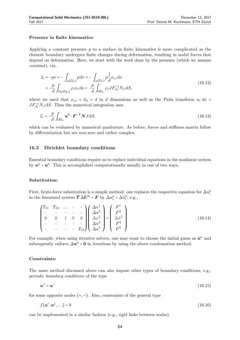
Computational Solid Mechanics (151-0519-00L) December 12, 2017Fall 2017 Prof. Dennis M. Kochmann, ETH Zurich
Pressure in finite kinematics:
Applying a constant pressure p to a surface in finite kinematics is more complicated as theelement boundary undergoes finite changes during deformation, resulting in nodal forces thatdepend on deformation. Here, we start with the work done by the pressure (which we assumeconstant), viz.
Ie = −pv = −∫ϕ(Ωe)
pdv = −∫ϕ(Ωe)
p1
dxi,idv
= −pd∫∂ϕ(Ωe)
ϕinids = −p
d∫∂Ωe
ϕiJF−1Ji NJ dS,
(16.12)
where we used that xi,i = δii = d in d dimensions as well as the Piola transform ni ds =JF −1
Ji NJ dS. Thus the numerical integration uses
Ie = −p
d∫∂Ωe
uh ⋅F −TNJ dS, (16.13)
which can be evaluated by numerical quadrature. As before, forces and stiffness matrix followby differentiation but are non-zero and rather complex.
16.3 Dirichlet boundary conditions
Essential boundary conditions require us to replace individual equations in the nonlinear systemby ua = ua. This is accomplished computationally usually in one of two ways.
Substitution:
First, brute-force substitution is a simple method: one replaces the respective equation for ∆uaiin the linearized system T ∆Uh = F by ∆uai = ∆uai ; e.g.,
⎛⎜⎜⎜⎜⎜⎜⎝
T11 T12 . . . ⋅ ⋅⋅ ⋅ ⋅ ⋅ ⋅0 0 1 0 0⋅ ⋅ ⋅ ⋅ ⋅⋅ ⋅ ⋅ ⋅ T55
⎞⎟⎟⎟⎟⎟⎟⎠
⎛⎜⎜⎜⎜⎜⎜⎝
∆u1
∆u2
∆u3
∆u4
∆u5
⎞⎟⎟⎟⎟⎟⎟⎠
=
⎛⎜⎜⎜⎜⎜⎜⎝
F 1
F 2
∆u3
F 4
F 5
⎞⎟⎟⎟⎟⎟⎟⎠
(16.14)
For example, when using iterative solvers, one may want to choose the initial guess as ua andsubsequently enforce ∆ua = 0 in iterations by using the above condensation method.
Constraints:
The same method discussed above can also impose other types of boundary conditions, e.g.,periodic boundary conditions of the type
u+ = u− (16.15)
for some opposite nodes (+,−). Also, constraints of the general type
f(ui,uj , . . .) = 0 (16.16)
can be implemented in a similar fashion (e.g., rigid links between nodes).
64

Computational Solid Mechanics (151-0519-00L) December 12, 2017Fall 2017 Prof. Dennis M. Kochmann, ETH Zurich
In case of linear constraints on boundary nodes, it is sometimes convenient to introduce areduced set of degrees of freedom Uh
red, which contains only the free degrees of freedom, fromwhich the full set of nodal degrees of freedom can be obtained via
Uh =AUhred, (16.17)
whereA is a matrix defined by the constraints. For example, consider a node a being constrainedto move along a particular direction n ∈ Rd. That is, its degrees of freedom ua = ua1, ua2 in 2Dare reduced2 to ua = χan with the only unknown being χa ∈ R. E.g., in 2D we have
Uh =
⎛⎜⎜⎜⎜⎜⎜⎜⎜⎜⎜⎜⎜⎜⎜⎜⎝
. . .⋅ 1 ⋅ ⋅ ⋅ ⋅ ⋅⋅ ⋅ 1 ⋅ ⋅ ⋅ ⋅⋅ ⋅ ⋅ n1 ⋅ ⋅ ⋅⋅ ⋅ ⋅ n2 ⋅ ⋅ ⋅⋅ ⋅ ⋅ n3 ⋅ ⋅ ⋅⋅ ⋅ ⋅ ⋅ 1 ⋅ ⋅⋅ ⋅ ⋅ ⋅ ⋅ 1 ⋅
. . .
⎞⎟⎟⎟⎟⎟⎟⎟⎟⎟⎟⎟⎟⎟⎟⎟⎠
⎛⎜⎜⎜⎜⎜⎜⎜⎜⎜⎜⎝
⋮ua−1
1
ua−12
χa
ua+11
ua+12
⋮
⎞⎟⎟⎟⎟⎟⎟⎟⎟⎟⎟⎠
=AUhred (16.18)
The governing equation now becomes
Fint (AUhred) −Fext = 0. (16.19)
Note that in the special case of a linear problem we know that Fint = TUh, so that (16.19) formcan be transformed into a symmetric problem by pre-multiplying by AT, i.e.,
ATTAUhred −A
TFext = 0 ⇔ TredUhred −Fext,red = 0, (16.20)
which is to be solved for the reduced degrees of freedom. While efficient due to the reducednumber of degrees of freedom, the pre- and post-multiplication by A can add considerablenumerical expenses.
Notice a convenient relation: if matrix A embeds Uhred according to (16.17), then the total forces
acting on the reduced degrees of freedom are given by ATF ; e.g., in the above example:
Fred =ATF =
⎛⎜⎜⎜⎜⎜⎜⎜⎜⎜⎜⎝
. . .⋅ 1 ⋅ ⋅ ⋅ ⋅ ⋅ ⋅ ⋅ ⋅⋅ ⋅ 1 ⋅ ⋅ ⋅ ⋅ ⋅ ⋅ ⋅⋅ ⋅ ⋅ n1 n2 n3 ⋅ ⋅ ⋅ ⋅⋅ ⋅ ⋅ ⋅ ⋅ ⋅ 1 ⋅ ⋅ ⋅⋅ ⋅ ⋅ ⋅ ⋅ ⋅ ⋅ 1 ⋅ ⋅
. . .
⎞⎟⎟⎟⎟⎟⎟⎟⎟⎟⎟⎠
F =
⎛⎜⎜⎜⎜⎜⎜⎝
⋮F a−1
F a ⋅nF a+1
⋮
⎞⎟⎟⎟⎟⎟⎟⎠
. (16.21)
Recall that in the nonlinear case, one may still solve for the reduced the linearized equation tocompute the Newton-Raphson updates is
∆Uhred = −(T
∗)−1(Uhred) [Fint(AUh
red) −Fext] where T ∗ =AT∂Fint
∂Uh(AUh
red). (16.22)
There are many alternative ways to introduce constraints such as using the penalty methodwhich appends to the potential energy each constraint with a penalty (Lagrange-type) multi-plier. For further information, please refer to the literature.
2This is an embedding operation: node a is constraint to lie on a line manifold and is embedded into 3D spacevia embedding. The inverse operation is known as submerging.
65

Computational Solid Mechanics (151-0519-00L) December 12, 2017Fall 2017 Prof. Dennis M. Kochmann, ETH Zurich
Condensation:
The substitution method introduced above for essential boundary conditions is simple to im-plement. However, it is quite expensive since the number of equations remains the same whenimposing essential boundary conditions. The condensation method removes from the linearsystem to be solved those equations imposing essential boundary conditions.
Let us rewrite the linearized system by moving the third column to the right-hand side:
⎛⎜⎜⎜⎜⎜⎜⎝
T11 T12 0 T14 ⋅⋅ ⋅ 0 ⋅ ⋅⋅ ⋅ 0 ⋅ ⋅⋅ ⋅ 0 ⋅ ⋅⋅ ⋅ 0 ⋅ T55
⎞⎟⎟⎟⎟⎟⎟⎠
⎛⎜⎜⎜⎜⎜⎜⎝
∆u1
∆u2
∆u3
∆u4
∆u5
⎞⎟⎟⎟⎟⎟⎟⎠
=
⎛⎜⎜⎜⎜⎜⎜⎝
F 1
F 2
F 3
F 4
F 5
⎞⎟⎟⎟⎟⎟⎟⎠
−
⎛⎜⎜⎜⎜⎜⎜⎝
∆T13
∆T23
∆T33
∆T43
∆T53
⎞⎟⎟⎟⎟⎟⎟⎠
∆u3 (16.23)
so that we can eliminate the third row and column from the system:
⎛⎜⎜⎜⎝
T11 T12 T14 ⋅⋅ ⋅ ⋅ ⋅⋅ ⋅ ⋅ ⋅⋅ ⋅ ⋅ T55
⎞⎟⎟⎟⎠
⎛⎜⎜⎜⎝
∆u1
∆u2
∆u4
∆u5
⎞⎟⎟⎟⎠=⎛⎜⎜⎜⎝
F 1
F 2
F 4
F 5
⎞⎟⎟⎟⎠−⎛⎜⎜⎜⎝
∆T13
∆T23
∆T43
∆T53
⎞⎟⎟⎟⎠
∆u3, (16.24)
and solve for the remaining unknowns along with ∆u3 = ∆u3.
The clear advantage of this method is the reduction in size of the system to be solved. Thedisadvantage is that it is computationally more involved (can be even more expensive for asmall number of essential boundary conditions applied to large systems).
16.4 Rigid body motion
Consider the composite deformation mapping x = ϕ∗(ϕ(X)) with x = ϕ(X) being an admissible
deformation mapping and ϕ∗(x) =Rx+c denoting rigid body motion, i.e.,R ∈ SO(d) and c ∈ Rdis a constant vector. Note that the combined deformation gradient is given by F ∗ =RF whereF = Gradϕ. Recall that the weak form read
G(u, v) = ∫ΩPiJ(F )vi,J dV − ∫
ΩRBividV − ∫
∂ΩNTividS = 0. (16.25)
Insertion of the composite mapping yields
G(u∗, v) = ∫ΩPiJ(RF )vi,J dV − ∫
ΩRBividV − ∫
∂ΩNTividS = 0. (16.26)
However, note that material frame indifference requires that P = P (C) and C∗ = (F ∗)TF ∗ =FTF = C, so that the rotation has no affect on the weak form (neither does the translation c).Therefore, rigid body motion can be superimposed onto any admissible solution and must besuppressed by appropriate essential boundary conditions to ensure uniqueness of solutions.
For the linear elastic case, the tangent matrix T therefore has as many zero eigenvalues as ithas rigid-body modes, or zero-energy modes U∗ such that
U∗ ⋅ TU∗ = 0. (16.27)
This implies that T has zero eigenvalues and is thus not invertible.
The remedy is to suppress rigid body modes via appropriate essential boundary conditions;specifically in d dimensions we need d(d − 1)/2 such essential boundary conditions.
66

Computational Solid Mechanics (151-0519-00L) December 12, 2017Fall 2017 Prof. Dennis M. Kochmann, ETH Zurich
17 Error estimates and adaptivity
17.1 Finite element error analysis
Solving systems of PDEs by the finite element method introduces numerous sources of errorsthat one should be aware of:
(i) The discretization error (also known as the first fundamental error) arises fromdiscretizing the domain into elements of finite size h. As a result, the body Ω is not repre-sented correctly and the model (e.g., the outer boundary) may not match the true bound-ary ∂Ω (e.g., think of approximating a circular domain Ω by CST or Q4 elements). Thiserror can be reduced by mesh refinement (and we discussed r-refinement, h-refinement,p-refinement, and hp-refinement).
(ii) The numerical integration error results from the application of numerical quadrature:
∫Ωef(ξ)dξ ≅
nQP
∑k=1
Wk f(ξk) (17.1)
We discussed that for f ∈ Ck+1(Ω) (the extension to higher dimensions is analogous)
RRRRRRRRRRR∫
1
−1f(ξ)dξ −
nQP
∑q=1
Wi f(ξi)RRRRRRRRRRR≤ C ∥Ω∥hk+1 max
ξ∈[−1,1]∣α∣=k+1
∥Dαf(ξ)∥ . (17.2)
Hence, the numerical integration error depends on the smoothness of the integrand andcalls for a proper choice of the integration order.
(iii) The solution error stems from numerically solving linear systems TUh = F . In general,the accuracy of the solution depends on the condition number of the matrix,
κ = ∥T ∥ ⋅ ∥T −1∥ = ∣λmax
λmin∣ (17.3)
with λmax (λmin) being the largest (smallest) eigenvalue of T . The higher the conditionnumber, the larger the numerical error.A practical consequence is the guideline to choose wisely the units of model parameters(such as material constants, domain size features, etc.). For example, when performing alinear elastic simulation, it is advisable to normalize elastic constants by 1 GPa insteadof assigning, e.g., E = 210 ⋅ 109 (instead, use E = 2.1 and know that your results will be in100 GPa’s).
(iv) An approximation error is introduced by approximating the functional space U (inwhich to find the solution u(x)) by a finite-dimensional subspace Uh ⊂ U .As an example, consider an exact solution u(x) in 1D which is approximated by a piece-wise linear polynomial function uh(x). The bar hanging from the ceiling under its ownweight was such an example, for which the solution was found to be exact at the nodeswith an error e(x) = u(x)− uh(x) arising within elements. Therefore, we can find a pointz within each element such that
∂e
∂x(z) = 0 for xi ≤ x ≤ xi+1. (17.4)
Consequently, we can expand the error to find the solution at a node as
e(xi) = 0 = e(z) + (xi − z)∂e
∂x(z) + (xi − z)2
2
∂2e
∂x2(z) +O((xi − z)3). (17.5)
67

Computational Solid Mechanics (151-0519-00L) December 12, 2017Fall 2017 Prof. Dennis M. Kochmann, ETH Zurich
Using (17.4), we find that
e(z) = −(xi − z)2
2
∂2e
∂x2(z) +O(h3). (17.6)
Note that
(xi − z)2 ≤ (xi+1 − xi2
)2
= h2
4, (17.7)
where h denotes the nodal spacing. Altogether, we have thus shown that the maximumerror in an element is bounded by
∣e(x)∣max ≤h2
8max
xi≤x≤xi+1∣∂
2u
∂x2∣ (17.8)
As shown in Appendix C, the above error bound can be significantly generalized. for aninterpolation of order k and u ∈Hk+1(Ω), we have
∣uh − u∣H1(Ω) ≤hk
πk∣u∣Hk+1(Ω) and ∥uh − u∥H1(Ω) ≤ ch
k ∣u∣Hk+1(Ω) , (17.9)
using Sobolev norms. Thus the error is again determined by the smoothness of the functionto be interpolated; and it is expected to decrease with decreasing element size (as h→ 0)– the faster the higher the interpolation order.Note that special caution is required if stress concentrations of any kind are to be rep-resented (e.g., imagine a linear elastic fracture problem and the issues arising from usinglinear elements to capture the 1/rn-type stress concentration near the crack tip).
(v) A truncation error is made by every computer when storing and operating numericvalues with only a finite number of digits (e.g., floats, doubles, etc.). This is unavoidableand one should be aware of what this error is (especially when choosing, e.g., solvertolerances). Choosing a solver tolerance in itself produces truncation error because wecontend with a solution Uh that satisfies Fint(Uh) −Fext = tol. (instead of being zero).
(vi) Finally, no simulation is free of modeling error, which refers to the large collection oferrors made by the selection of the analytical model to be solved (before starting anynumerical approximation). For example, we make choices for an appropriate materialmodel, choose material parameters, boundary conditions, and geometric simplificationsincluding reductions to lower dimensions (e.g., plane strain or plane stress instead of a 3Dsimulation).
The sum of all of the above error sources makes up the numerical error inherent in everysimulation.
17.2 Smoothing and adaptivity
Both for postprocessing of approximate solutions and for mesh adaptivity (discussed below) itis convenient to introduce a smoothing scheme that takes piecewise-defined solutions (e.g., thestress and strain fields in case of simplicial elements) and computes smoothed nodal values ofthe discontinuous quantities.
In case of simplicial elements, the quantities of interest are constant within elements. Here onecan define nodal quantities, e.g., as
(ua)∗ =∑nnbj=1 ue,j/Ve,j∑nnbj=1 1/Ve,j
, (17.10)
68

Computational Solid Mechanics (151-0519-00L) December 12, 2017Fall 2017 Prof. Dennis M. Kochmann, ETH Zurich
where the element quantities ue of all nnb neighboring elements meeting at a node a are weightedby the respective element volume Ve. This weighting results in smaller elements (whose quadra-ture points are closer to the node) having a larger weight than large elements (where quadraturepoints are far from the node).
In case of higher-order elements such as, e.g., the Q4 element, one can extrapolate elementquantities that are defined at the quadrature points ξk to the nodes by invoking the definitionthat
u(ξk) =n
∑a=1
(ua)∗Na(ξk). (17.11)
For example for the Q4 element, there are four nodes and four quadrature points, so that thefour equations can be solved for the four nodal values ua. Once the nodal values are known,one again uses a smoothing relation like (17.10) with the element quantities ue,j replaced bythe nodal value uae from the respective element, and element volume Ve replaced by the nodalweight (obtained from extrapolating the quadrature point weights WkJkt to the nodes).
When performing adaptive mesh refinement, we need an error norm where, as an example, wediscuss the ZZ error estimator named after its inventors, Zienkiewicz and Zhu. If we use asmoothing scheme like the above, we can define a smoothed, continuous displacement gradient∇u∗ which is contrasted with the approximate solution ∇uh, so that one may define the errorper element by using the energy norm, viz.
∥e(∇u,∇u∗)∥2e = ∫
ΩeW (∇u∗ −∇u)dV. (17.12)
Note that this definition is not unique and one could also use the L2-norm
∥e∥2e = ∫
Ωe∥∇u∗ −∇u∥ dV. (17.13)
or any other sensible norm.
In order to define an error estimate, it makes sense to introduce the normalization
ηe =∥e(∇u,∇u∗)∥e∥e(∇u,0)∥e
, (17.14)
i.e., the error is divided by the energy in the element so as to not over- or underestimate elementerrors based on element sizes as well as in case of vast differences in element strain energies.The mesh refinement criterion states that an element is refined if
ηe > ηtol. (17.15)
with some tolerance ηtol. determined as a compromise between accuracy and efficiency. Basedon the refinement criterion, a set of elements can be identified after each equilibration which isflagged for refinement.
Needed next is a mesh refinement algorithm. For exapmle, a frequent choice for triangularelements is longest edge bisection, which identifies the longest edge in an element to berefined and inserts a new node at this edge’s midpoint, followed by an update of the elementconnectivity (removing two existing elements and creating four new elements). Note that thisinvolves some book-keeping since adjacent elements flagged for refinement interfere, so that oneneeds an algorithmic decision about which elements to refine first and how to handle adjacentelements identified for refinement, etc.
69

Computational Solid Mechanics (151-0519-00L) December 12, 2017Fall 2017 Prof. Dennis M. Kochmann, ETH Zurich
18 Element defects: shear locking and hourglassing
Elements make specific approximations about how displacements, stresses and strains vary insideeach element, and these approximations may introduce errors. Aside from the above generalnumerical errors stemming from the interpolation order, the quadrature rule, and geometricerrors, etc., particular elements can have defects, some of which will discussed in the following.
The bilinear Q4 element displays a defect when used to simulate beam bending. Consider arectangular element having side lengths a and b in the x and y directions. If bending momentsM are applied on the two vertical edges, then the element is expected to undergo bending.
In an actual (slender) beam, we know from elastic beam theory that the stresses in the beamvary linearly across the thickness, so we may write
σxx = −y
bσmax, σyy = σxy = 0, (18.1)
where σmax is the maximum tensile stress reached on the surface of the beam. From Hooke’slaw we obtain
εxx = −σxxE
= −yσmax
bE, εyy = −ν
σxxE
= ν yσmax
bE, εxy = 0. (18.2)
Let us try to find this solution using a Q4 element. To this end, we apply horizontal forces to allfour nodes of the element, obtained from lumping the distributed beam stresses to the nodes:
Fext,1 = ∫∂Ωe
σxxN1e dS = −∫
1
−1(−ybσmax)N1
e (ξ, η) tbdη
= ∫1
−1η σmax
(1 − ξ)(1 − η)4
tbdη = −σmaxtb
3= −F,
(18.3)
where we introduced the abbreviation F = σmaxtb3 for convenience. Analogously, one obtains
Fext,2 = F, Fext,3 = −F, Fext,4 = F. (18.4)
That is, the bottom edge is stretched, while the top edge is compressed (as in beam bending).
Solving the problem for the case of linear elasticity reduces to a simple linear system of equations:
KeUhe = Fext =
⎛⎜⎜⎜⎜⎜⎜⎜⎜⎜⎜⎜⎜⎜⎝
−F0F0−F0F0
⎞⎟⎟⎟⎟⎟⎟⎟⎟⎟⎟⎟⎟⎟⎠
⇒ Uhe =
⎛⎜⎜⎜⎜⎜⎜⎜⎜⎜⎜⎜⎜⎜⎝
−U0U0−U0U0
⎞⎟⎟⎟⎟⎟⎟⎟⎟⎟⎟⎟⎟⎟⎠
with U = 2aσmax
E
(1 + ν)(1 − 2ν)2(1 − ν) + (an)2(1 − 2ν)
,
(18.5)
where we evaluated all element forces and stiffness matrices exactly (without quadrature errors).
The resulting strains are evaluated as
εxx = −U
aη, εyy = 0, εxy = −
U
bξ. (18.6)
70

Computational Solid Mechanics (151-0519-00L) December 12, 2017Fall 2017 Prof. Dennis M. Kochmann, ETH Zurich
While the axial strain component is reasonable, the presence of a shear stress is problematic.This so-called parasitic shear is not physical but a numerical artifact (elastic Euler beamsproduce no shear stresses). This parasitic shear contributes to the energy of the element, so that– when minimizing the potential energy in a boundary value problem – this shear componentintroduces artificial stiffness. This becomes apparent when calculating, e.g., the angle of bendingθ of the beam in the above problem. Comparing the exact one (obtained form beam theory) tothe approximate one (obtained from the above construction), one finds
θapprox
θexact=
1 − ν2
1 +1 − ν
2(a
b)
2. (18.7)
Notice that, as the Q4 element becomes more and more slender (a/b → ∞), the numericallyobtained angle approaches 0. That is, the element shows what is known as locking or, morespecifically, shear locking: in case of very slender elements (a/b ≪ 1) the high shear strainand associated elastic energy prevents the element from deformting, it “locks”.
Next, let us use numerical quadrature to evaluate the element quantities of interest. For exam-ple, for the energy we have
Ie = ∫Ωe
1
2εh ⋅CεhdV ≈ t
2
nQP−1
∑k=0
Wk εh(ξk) ⋅Cεh(ξk)J(ξk). (18.8)
We showed before that full integration requires nQP = 2×2 quadrature points. If instead we usereduced integration with only a single quadrature point (nQP = 1) located at ξ0 = 0, then noticethat strain fields of the form (18.6) – which vanish at ξ = η = 0 – produce no energy. In otherwords, any strain field of the form (18.6) can appear without causing any energy and thereforealso without causing any resistance. This is a zero-energy mode of the under-integratedQ4 element and a serious defect. The resulting deformation of elements undergoing alternatingstrains (18.6) is a numerical artifact and often referred to as hourglass mode or chicken-wiremode because of its appearance.
Note that note only the underintegrated Q4 element has such a zero-energy mode. For example,the Q8/Q9 elements have a similar zero-energy mode with curved element edges.
Finally, it is possible to use selective integration, which applies different quadrature rules fordifferent energy contributions. For example, integrating the Q4 element with a 2×2 quadraturerule for the nominal strains εxx and εyy while using reduced integration with a single quadraturepoint at ξk = 0 removes the spurious shear contribution while maintaining the correct stiffnessagainst axial deformation. Notice that, however, selective integration is harder to implement,not directly applicable beyond linear elasticity, and should be used with caution.
71

Computational Solid Mechanics (151-0519-00L) December 12, 2017Fall 2017 Prof. Dennis M. Kochmann, ETH Zurich
19 Dynamics
19.1 Variational setting
The mechanical problems so far have been limited to quasistatic conditions. Let us considerthe extension to dynamic problems where inertial effects matter and the strong form reads (forsimplicity stated in linearized kinematics; the finite-deformation setting is analogous)
⎡⎢⎢⎢⎢⎢⎢⎣
σij,j + ρ bi = ρai in Ω
ui(x, t) = ui(x, t) on ∂ΩD
σijnj(x, t) = t(x, t) on ∂ΩN
(19.1)
Now, we have u ∶ Ω ×R→ Rd with sufficient differentiability in both space and time.
The variational approach here makes use of the so-called action principle which uses theaction
A[u] = ∫t2
t1L[u]dt with L[u] = T [u] − I[u], (19.2)
where I is the potential energy functional from before and T the kinetic energy functional:
T [u] = ∫Ω
ρ
2∣u∣2 dV. (19.3)
The action principle states that the solution u(x, t) renders A stationary with u(x, t1) =u1(x) and u(x, t2) = u2(x).
For variational material models (with W replaced by W ∗ for inelasticity), we have
A[u] = ∫t2
t1[∫
Ω(ρ
2∣u∣2 −W (ε)) dV + ∫
Ωρb ⋅u dV + ∫
∂ΩNt ⋅u dS] dt. (19.4)
Taking the first variation (with the divergence theorem and the same assumptions from before):
δA[u] = 0 = ∫t2
t1[∫
Ω(ρ ui δui − σijδui,j) dV + ∫
Ωρbiδui dV + ∫
∂ΩNtiδuidS] dt. (19.5)
The weak form is thus obtained as
G(u, v) = ∫t2
t1[∫
Ω(ρ ui vi − σijvi,j) dV + ∫
Ωρbivi dV + ∫
∂ΩNtividS] dt = 0 (19.6)
with
v ∈ v ∈H1(Ω) ∶ v = 0 on ∂ΩD and at t = t1 or t = t2 . (19.7)
To avoid the time derivative in the variation, let us integrate by parts in time (the “boundaryterm” vanishes since v = 0 at t = t1 and t = t2):
G(u, v) = −∫t2
t1[∫
Ω(ρ ui vi + σijvi,j) dV − ∫
Ωρbivi dV − ∫
∂ΩNtividS] dt = 0. (19.8)
Note that, without the first term, we recover the elastostatic formulation.
72

Computational Solid Mechanics (151-0519-00L) December 12, 2017Fall 2017 Prof. Dennis M. Kochmann, ETH Zurich
Since in the dynamic problem the displacement field depends on time, we introduce a semi-discretization, i.e., we discretize the solution in space but not in time:
uh(x, t) =n
∑a=1
ua(t)Na(x) and vh(x, t) =n
∑a=1
va(t)Na(x), (19.9)
so that
uh(x, t) =n
∑a=1
ua(t)Na(x) and uh(x, t) =n
∑a=1
ua(t)Na(x). (19.10)
Insertion into the weak form results in Galerkin’s discrete weak form:
G(uh,vh) = −∫t2
t1
n
∑a=1
n
∑b=1
[uai vbi ∫ΩρNaN bdV + vbi ∫
ΩσijN
b,j dV
−vbi ∫ΩρbiN
b dV − vbi ∫∂ΩN
tiNbdS] dt = 0
(19.11)
for all vb(t) histories that vanish at t1 and t2.
Analogously to before, we now write
Uh(t) = u1(t), . . . ,un(t), (19.12)
so that solving (19.11) for all vb(t) is equivalent to solving
M Uh +Fint(Uh) −Fext(t) = 0 (19.13)
with
Mabij = δij ∫
ΩρNaN bdV, F bint,i = ∫
ΩσijN
b,j dV, F bext,i = ∫
ΩρbiN
b dV +∫∂ΩN
tiNbdS.
(19.14)
Matrix M is called the consistent mass matrix.
Examples:
The consistent mass matrix for a two-node bar element is computed from shape functions
N1(ξ) =1 − ξ
2, N2(ξ) =
1 + ξ2
. (19.15)
Specifically, we have (with m = ρALe)
Mab = ∫ΩρNaN bdV = ∫
1
−1ρNaN bA
Le2
dxi ⇒ M1D = m6
(2 11 2
) . (19.16)
Note that this is the consistent mass matrix for 1D motion. If each node moves has two degreesof freedom (u1, u2) in the plane, then each pair of dof is linked by the above mass matrix, sothat the total consistent mass matrix becomes
M2D = m6
⎛⎜⎜⎜⎝
2 0 1 00 2 0 11 0 2 00 1 0 2
⎞⎟⎟⎟⎠. (19.17)
73

Computational Solid Mechanics (151-0519-00L) December 12, 2017Fall 2017 Prof. Dennis M. Kochmann, ETH Zurich
Similarly, the consistent mass matrix of the CST is computed by integration of the shapefunctions, resulting for 1D motion in
MCST = m
12
⎛⎜⎝
2 1 11 2 11 1 2
⎞⎟⎠
with m = ρAt. (19.18)
As before, the corresponding mass matrix for 2D motion is obtained by applying the abovematrix for each dof independently.
For other (non-simplicial) elements, the stiffness matrix can be evaluated analogously or com-puted by numerical quadrature:
Mab = ∫ΩρNaN bdV ≈
nQP−1
∑k=0
WkρNa(ξk)N b(ξk)J(ξk). (19.19)
In summary, the dynamic problem is quite analogous to the quasistatic one. The key differenceis the first term in (19.13), which requires a strategy to obtain numerical solutions that are time-dependent. Note that the above formulation in linearized kinematics can easily be adopted forfinite deformations (the final matrix equations are the same with internal/external forcevectors replaced by the finite-deformation counterparts).
We note that various references call this dynamic variational principle the “principle of leastaction” or “principle of minimum action”, which is in fact not correct since the solution mustnot necessarily be a minimizer of A (it is merely guaranteed to be an extremizer).
The consistent mass matrix above is dense, which may be inconvenient for numerical solutions.Therefore, one often resorts to the so-called lumped mass matrix which is an approximationthat is diagonal. For example, by using particle-mass lumping for a 2-node bar element, onedistributes the mass evenly to the two end points, resulting in
M1D = m2
(1 00 1
) , M2D = m2
⎛⎜⎜⎜⎝
1 0 0 00 1 0 00 0 1 00 0 0 1
⎞⎟⎟⎟⎠. (19.20)
Note that a comparison of the kinetic energies (e.g., in 1D) reveals
Tlumped =1
2Uhe ⋅MlumpedU
he = m
4[(u1
e)2 + (u2e)2] (19.21)
and
Tconsistent =1
2Uhe ⋅MconsistentU
he = m
6[(u1
e)2 + (u2e)2 + u1
eu2e] . (19.22)
Hence, the lumped mass matrix yields to an approximation of the kinetic energy (which isgenerally not exact).
Particle-mass lumping can be extended to arbitrary elements having n nodes by defining
M = mnI. (19.23)
Finally, note that in structural dynamics, one often includes velocity-proportional dampingthrough a damping matrix C such that (19.13) turns into
M Uh +C Uh +Fint(Uh) −Fext(t) = 0 (19.24)
74

Computational Solid Mechanics (151-0519-00L) December 12, 2017Fall 2017 Prof. Dennis M. Kochmann, ETH Zurich
with, oftentimes, mass- and stiffness-proportional damping via
C = αM + βK, α, β ∈ R+. (19.25)
The choice of α > 0 controls low-frequency vibration attenuation, while β > 0 suppresses high-frequency vibrations.
19.2 Free vibrations
Free vibrations of infinitesimal amplitude are a frequent case of interest. Starting with thegeneral, nonlinear equations of motion,
M Uh +Fint(Uh) = Fext(t), (19.26)
we linearize about a stable equilibrium configuration Uh0 with constant forces Fext = Fext,0
such that Fint(Uh0 ) = Fext,0. Consider now a small time-varying perturbation δUh(t) such that
Uh = Uh0 + δUh gives to leading order
M δUh +Fint(Uh0 ) + ∂Fint
∂Uh(Uh
0 ) δUh + h.o.t. = Fext,0 (19.27)
or, invoking equilibrium,
M δUh + T (Uh0 ) δUh + h.o.t. = 0. (19.28)
Similarly, when considering free vibrations about the undeformed ground state of an elasticbody, we would have arrived immediately at
M Uh +KUh = 0. (19.29)
Thus, (19.28) is the generalized form of (19.29) for equilibrated systems. In both cases theform of the equation of motion governing free vibrations without external forcing and withoutdamping is
M Uh + TUh = 0. (19.30)
The solution to the above ODE is of the separable form
Uh = Uh exp(iωt). (19.31)
Insertion into (19.30) leads to (exploiting that the equation must hold for all times t)
(T − ω2M) Uh = 0, (19.32)
which is an eigenvalue problem with eigenfrequency ω and eigenvector Uh. The latteris also referred to as the eigenmode.
For a FE discretization with ndof = dnn degrees of freedom (nn nodes in d dimensions), theeigenvalue problem has ndof eigenfrequencies with ndof associated distinct eigenmodes. Eachrigid body mode of the FE problem corresponds to a zero eigenfrequency. Therefore, a 2D (3D)free vibrational problem without essential BCs has 3 (6) zero eigenfrequencies.
75

Computational Solid Mechanics (151-0519-00L) December 12, 2017Fall 2017 Prof. Dennis M. Kochmann, ETH Zurich
Example: free vibration of a bar
We can use the exampe of a freely vibrating bar to assess the influence of the different massmatrices. Consider a 2-node bar element with only axial displacements, so that each node hasonly a single degree of freedom ui. The mass matrices and the stiffness matrix for this casewere derived previously as
Mconsistent =m
6(2 1
1 2) , Mlumped =
m
2(1 0
0 1) , K = EA
L( 1 −1−1 1
) . (19.33)
In both cases of the lumped and consistent mass matrices, we compute the two eigenfrequenciesand eigenmodes by solving the eigenvalue problem
(K − ω2M)Uh = 0 ⇒ det (K − ω2M) = 0. (19.34)
Insertion of the stiffness and consistent mass matrix results in the two solutions
ωconsistent0 = 0, ωconsistent
1 =√
12EA
mL≈ 3.464
√EA
mL. (19.35)
The corresponding eigenvectors follow from insertion of the eigenfrequencies into the eigenvalueproblem, giving
U consistent0 = (1
1) , U consistent
1 = ( 1−1
) . (19.36)
As expected, we have one zero eigenfrequency associated with rigid body translation. Whenrepeating the above procedure with the lumped mass matrix, we instead obtain
ωlumped0 = 0, ωlumped
1 = 2
√EA
mL. (19.37)
and
U lumped0 = (1
1) , U lumped
1 = ( 1−1
) . (19.38)
Hence, the two cases yield the same eigenmodes but significantly differ in the fundamentalfrequency. For comparison, let us compute the exact solution by studying the free vibration ofa continuous, homogeneous, linear elastic bar. Linear momentum balance, i.e.,
Eu,xx = ρu, (19.39)
admits the separable solution
u(x, t) = u(x) exp(iωt) ⇒ Eu,xx(x) = −ω2ρu(x) (19.40)
Free-end boundary conditions imply that
u,x(0) = u,x(L) ⇒ u(x) = A cos(nπxL
) (19.41)
with an integer n and a constant A ∈ R. Insertion into (19.39) leads to
−E (nπL
)2
= −ω2ρ ⇒ ωn = nπ√
EA
mL. (19.42)
76

Computational Solid Mechanics (151-0519-00L) December 12, 2017Fall 2017 Prof. Dennis M. Kochmann, ETH Zurich
Consequently, the eigenfrequencies are obtained as
ω0 = 0, ω1 = π√
EA
mL. (19.43)
Comparison with the above two cases results in
ωlumped1 ≤ ω1 ≤ ωconsistent
1 . (19.44)
Note that the eigenfrequency obtained from the consistent mass matrix is an upper bound onthe eigenfrequency, while the lumped mass matrix is usually a lower bound (the latter is notrigorous, though, since it depends on the choice of the lumped mass matrix).
19.3 Modal decomposition
Let us introduce a few important features of the eigenmodes discussed above. By consideringthe eigenvalue problem for two distinct eigenmodes/-frequencies, we may write
(T − ω2iM) Uh
i = 0 ⇒ Uhj ⋅ (T − ω2
iM) Uhi = 0,
(T − ω2jM) Uh
j = 0 ⇒ Uhi ⋅ (T − ω2
jM) Uhj = 0,
(19.45)
where we simply pre-multiplied each of the two equations by the respective other eigenvector.Subtraction of the two equations (using that T is by definition symmetric) results in
(ω2i − ω2
j ) Uhi ⋅M Uh
j = 0. (19.46)
This implies that either ωi = ωj (considering only positive eigenfrequencies) or Uhi ⋅M Uh
j . If weeliminate duplicated eigenfrequencies by, e.g., Gram-Schmid orthonormalization, then we mayconclude that
Uhi ⋅M Uh
j = 0 if i ≠ j. (19.47)
We can normalize the eigenvectors in the following fashion:
Uhi ←
Uhi√
Uhi ⋅M Uh
i
⇒ Uhi ⋅M Uh
i = 1, (19.48)
so that overall
Uhi ⋅M Uh
j = δij . (19.49)
If we now consider
(T − ω2iM) Uh
i = 0 ⇒ Uhj ⋅ (T − ω2
iM) Uhi = 0, (19.50)
then we may also conclude that, by invoking (19.49),
Uhj ⋅ T Uh
i = 0 if i ≠ j. (19.51)
Similarly, by pre-multiplying by the respective same eigenvector, i.e.,
Uhi ⋅ (T − ω2
iM) Uhi = 0, (19.52)
77

Computational Solid Mechanics (151-0519-00L) December 12, 2017Fall 2017 Prof. Dennis M. Kochmann, ETH Zurich
we solve for ω2i and obtain Rayleigh’s quotient, which here simplifies due to the normalization:
ω2i =
Uh(i) ⋅ T U
h(i)
U(i) ⋅MUh(i)
= Uh(i) ⋅ T U
h(i). (19.53)
This all forms the basis for the method known as modal decomposition.
The starting point for modal decomposition of linearized, elastic system is the Fourier repre-sentation
Uh(t) =n
∑i=1
zi(t) Uhi , (19.54)
where Uh1 , . . . , U
hn are the n eigenmodes of the system. That is, we pre-compute the eigenvec-
tors and seek a solution as a linear superposition of all eigenvectors with some unknown scalarcoefficients that are continuous functions of time (maintaining the semi -discretization).
We substitute (19.54) into the linearized equations of motion with external forces,MUh+TUh =Fext, and pre-multiply the system of equations by Uh
i , so we arrive at
n
∑i=1
[zi(t)MUhi + zi(t)T Uh
i ] = Fext(t). (19.55)
Pre-multiplying by Uhj and exploiting the above orthogonality gives
n
∑i=1
[zi(t) Uhj ⋅MUh
i + zi(t)Uhj ⋅ T Uh
i ] = Uhj ⋅Fext(t) ⇔ zj(t)+ω2
j zj(t) = Uhj ⋅Fext(t),
(19.56)
where no summation over j is implied. This equation is quite remarkable as it is a scalar,linear ODE for the unknown function zj(t). Moreover, the system of equations for n unknownequations zi(t) (with i = 1, . . . , n) has decoupled into n uncoupled scalar ODEs to be solvedindependently for the zi(t). The strategy is thus to first pre-compute all eigenfrequencies ωiand all eigenmodes Uh
j , so that the coefficients and right-hand sides are known in
zi(t) + ω2i zi(t) = Uh
i ⋅Fext(t), (19.57)
which can relatively inexpensively be solved for functions zi(t).
For many practical problems, only a limited number of modes are important (i.e., taking thefirst m < n modes only). Therefore, numerical efficiency can be gained by truncating the Fouriersum, which is often referred to as order reduction:
Uh(t) =m
∑i=1
zi(t) Uhi , m < n. (19.58)
19.4 Transient time-dependent solutions
The time-dependent solution for the nodal variables Uh(t) is obtained either in a continuousmanner (e.g., by modal decomposition or in case of free vibrations as discussed above) or in atime-discretized fashion (e.g., by using finite-difference approximations in time). The turns thesemi -discretization into a proper discretization in both space and time.
78

Computational Solid Mechanics (151-0519-00L) December 12, 2017Fall 2017 Prof. Dennis M. Kochmann, ETH Zurich
19.5 Explicit time integration
We discretize the solution in time, e.g., we assume constant time increments ∆t > 0 and write
ua(tα) = ua,α, ∆t = tα+1 − tα. (19.59)
By using central-difference approximations, we obtain
Uh(tα) = Uh,α+1 −Uh,α−1
2∆t, Uh(tα) = U
h,α+1 − 2Uh,α +Uh,α−1
(∆t)2. (19.60)
Insertion into (19.24) leads to
MUh,α+1 − 2Uh,α +Uh,α−1
(∆t)2+CU
h,α+1 −Uh,α−1
2∆t+Fint(Uh,α) −Fext(tα) = 0, (19.61)
which can be reorganized into
[ M
(∆t)2+ C
2∆t]Uα+1 = 2M
(∆t)2Uα + [ C
2∆t− M
(∆t)2]Uα−1 −Fint (Uh,α) +Fext(tα). (19.62)
This is an update rule for Uα+1, using explicit time integration. Note that here and in thefollowing we drop the superscript h for simplicity and to avoid confusion with the time stepsuperscript α.
Note that stability limits the time step of the explicit scheme. Specifically, we must ensure that
∆t ≤ ∆tcr =2
ωmax, (19.63)
with ωmax being the highest eigenfrequency. Note that the highest eigenfrequency scales in-versely proportional to the smallest element size. For example, recall the two-node bar forwhich the eigenfrequency was of the form ω1 ∝ 1
L
√E/ρ with L being the element size.
19.6 A reinterpretation of finite differences
Instead of introducing finite differences as done above, we could alternatively use interpolationfunctions in both space and time. For example, consider a discretization in time which evaluatesUh at discrete time intervals ∆t and then uses a quadratic interpolation in time, i.e., we define
Uh(t) = Uα+1Nα+1(t) +UαNα(t) +Uα−1Nα−1(t) for t ∈ [tα − ∆t2 , t
α + ∆t2 ]. (19.64)
where we dropped the superscript h for simplicity. Shape functions N(t) interpolate in time.The chosen quadratic interpolation and the range of validity ensure that Uh(t) is twice differ-entiable (as needed for the acceleration) if
Nα+1(t) = (t − tα)(t − tα−1)2(∆t)2
, Nα(t) = (tα+1 − t)(t − tα−1)(∆t)2
, Nα−1(t) = (tα+1 − t)(tα − t)2(∆t)2
.
(19.65)
This choice ensures that
∂
∂tNα+1(tα − ∆t
2 ) = 0 and∂
∂tNα−1(tα + ∆t
2 ) = 0, (19.66)
79

Computational Solid Mechanics (151-0519-00L) December 12, 2017Fall 2017 Prof. Dennis M. Kochmann, ETH Zurich
so that Uh(t) is indeed continuous. The acceleration evaluates to
Uh(t) = Uα+1Nα+1(t) +UαNα(t) +Uα−1Nα−1(t)
= Uα+1
(∆t)2− 2
Uα
(∆t)2+ U
α−1
(∆t)2= U
α+1 − 2Uα +Uα−1
(∆t)2.
(19.67)
Thus, we recover the second-order central-difference scheme in time.
The full, discretized displacement field is now
uh(x, t) =n
∑a=1
α+1
∑γ=α−1
ua,γNγ(t)Na(x) for t ∈ [tα − ∆t2 , t
α + ∆t2 ], (19.68)
where ua,γ is the displacement at node a at time tγ . The acceleration field follows as thepiecewise-constant approximation
uh(x, t) =n
∑a=1
ua,α+1 − 2ua,α +ua,α−1
(∆t)2Na(x) for t ∈ [tα − ∆t
2 , tα + ∆t
2 ]. (19.69)
Next, one may wish to evaluate information at the nt discrete time steps, motivating the choiceof the trial function as
vh(x, t) =n
∑b=1
vb(t)N b(x) =n
∑b=1
nt
∑α=1
vb,αN b(x)δ(t − tα) (19.70)
When this choice of vh along with uh into the weak form, which derived earlier as
G(u, v) = ∫t2
t1[∫
Ω(−ρ uivi − σijvi,j) dV + ∫
Ωρbivi dV + ∫
∂ΩNtividS] dt = 0, (19.71)
then we may integrate explicitly with respect to time, resulting in
nt
∑b=1
vbi
⎡⎢⎢⎢⎢⎣∫
Ω
⎛⎝−ρua,α+1i − 2ua,αi + ua,α−1
i
(∆t)2NaN b − σij(∇uα)N b
,j
⎞⎠
dV
+∫Ωρbi(tα)N b dV + ∫
∂ΩNti(tα)N bdS] = 0
(19.72)
for each time step tα and for all admissible choices of vbi . The latter implies that we must have
∫ΩρNaN b dV
ua,α+1i − 2ua,αi + ua,α−1
i
(∆t)2+ ∫
Ωσij(∇uα)N b
,j dV
− ∫Ωρbi(tα)N b dV − ∫
∂ΩNti(tα)N bdS = 0.
(19.73)
This, however, is equivalent to
MUh,α+1 − 2Uh,α +Uh,α−1
(∆t)2+Fint(Uh,α) −Fext(tα) = 0, (19.74)
which was derived above for a second-order finite-difference time discretization, see (19.61).
80

Computational Solid Mechanics (151-0519-00L) December 12, 2017Fall 2017 Prof. Dennis M. Kochmann, ETH Zurich
19.7 Implicit time integration
Next, implicit time integration uses the same discretization in time but requires solving a(non)linear system of equations for Uα+1.
The most popular scheme for mechanical problems, is the so-called Newmark-β method whichis a combination of the linear acceleration and average acceleration schemes. Specifically, oneassumes
Uα+1 = Uα +∆t Uα + (∆t)2
2[2β Uα+1 + (1 − 2β)Uα] (19.75a)
Uα+1 = Uα +∆t [γUα+1 + (1 − γ)Uα] (19.75b)
with parameters 0 ≤ β ≤ γ/2 and 0 ≤ γ ≤ 1, often chosen as
β = 14 , γ = 1
2 in the average acceleration scheme, which is implicit and unconditionallystable (the underlying approximation is that the acceleration within the time interval ∆tremains constant).
β = 16 , γ = 1
2 in the linear acceleration scheme,
β = γ = 0 returns to the explicit central-difference scheme discussed above.
Most popular is the average accelerations scheme which is unconditionally stable for arbitrary∆t > 0.
For linear structural dynamics problems, the method is unconditionally stable if 2β ≥ γ ≥ 1/2.It is conditionally stable if γ < 1/2. For γ = 1/2 the scheme is at least second-order accurate,while being first-order accurate otherwise.
For implementation purposes, let us solve (19.75) for the acceleration at the new time tα+1:
Uα+1 = 1
β(∆t)2(Uα+1 −Uα −∆t Uα) − 1 − 2β
2βUα. (19.76)
Insertion into (19.75b) yields
Uα+1 = Uα +∆t(1 − γ)Uα + γ
β∆t(Uα+1 −Uα +∆t Uα) − γ∆t
1 − 2β
2βUα
= (1 − γβ) Uα + γ
β∆t(Uα+1 −Uα) −∆t( γ
2β− 1) Uα
(19.77)
Next, inserting both velocity (19.76) and acceleration (19.77) into the equation of motion atthe new time tα+1,
MUα+1 +CUα+1 +Fint(Uα+1) −Fext(tα+1) = 0, (19.78)
leads after some rearrangement to
( 1
β(∆t)2M + γ
β∆tC)Uα+1 +Fint(Uα+1) −Fext(tα+1)
=M [ 1
β(∆t)2Uα + 1
β∆tUα + ( 1
2β− 1) Uα]
+C [ γ
β∆tUα + (γ
β− 1) Uα +∆t( γ
2β− 1) Uα] .
(19.79)
81
Computational Solid Mechanics (151-0519-00L) December 12, 2017Fall 2017 Prof. Dennis M. Kochmann, ETH Zurich
The right-hand side is fully known as it only involves Uα, Uα, and Uα from the previous timestep. The left-hand side is generally nonlinear and requires an iterative solver.
Note that the implementation is quite similar to that of the quasistatic Newton-Raphson solverdiscussed before. The right-hand side is significantly longer (but contains only known informa-tion). The left-hand side is extended by the first term in (19.79), which is linear in Uα+1 andthe tangent matrix used for iterations is simply
T ∗ = 1
β(∆t)2M + γ
β∆tC + T . (19.80)
Boundary conditions can be implemented in the same fashion as for the quasistatic solversdiscussed above.
As an alternative derivation of the implementation, we may introduce the changes in dis-placements, velocities and accelerations during a time step as
∆Uα = Uα+1 −Uα, ∆Uα = Uα+1 − Uα, ∆Uα = Uα+1 − Uα. (19.81)
We can rearrange the first equation of (19.75) into
Uα+1 −Uα = ∆t Uα + (∆t)2
2[2β(Uα+1 − Uα) + Uα] (19.82)
or
∆Uα = ∆t Uα + (∆t)2
2[2β∆Uα + Uα] ⇔ ∆Uα = 1
β(∆t)2∆Uα − 1
β∆tUα − 1
2βUα.
(19.83)
Similarly, the second equation of (19.75) gives
Uα+1 − Uα = ∆t [γ(Uα+1 − Uα) + Uα] ⇔ ∆Uα = ∆t γ∆Uα +∆t Uα, (19.84)
so that insertion of the final result in (19.83) results in
∆Uα = ∆t γ [ 1
β(∆t)2∆Uα − 1
β∆tUα − 1
2βUα] +∆t Uα
= γ
β∆t∆Uα − γ
βUα +∆t(1 − γ
2β) Uα.
(19.85)
The equations of motion (19.24) in their general time-discretized form are
M Uα+1 +C Uα+1 +Fint(Uα+1) −Fext(tα+1) = 0. (19.86)
Subtracting the above equation for two consecutive time steps results in the incremental form
M ∆Uα +C∆Uα +Fint(Uα+1) −Fint(Uα) − [Fext(tα+1) −Fext(tα)] = 0. (19.87)
Now inserting (19.83) and (19.85) leads to
M [ 1
β(∆t)2∆Uα − 1
β∆tUα − 1
2βUα] +C [ γ
β∆t∆Uα − γ
βUα +∆t(1 − γ
2β) Uα]
+Fint(Uα+1) −Fint(Uα) − [Fext(tα+1) −Fext(tα)] = 0,
(19.88)
82

Computational Solid Mechanics (151-0519-00L) December 12, 2017Fall 2017 Prof. Dennis M. Kochmann, ETH Zurich
which can be regrouped into
[ 1
β(∆t)2M + γ
β∆tC]∆Uα +Fint(Uα+1) = Fext(tα+1) −Fext(tα) +Fint(Uα)
− [− 1
2βM +∆t(1 − γ
2β)C] Uα − [− 1
β∆tM − γ
βC] Uα,
(19.89)
whose right-hand side is entirely known from the previous time step (and the external forcesat the current time). Noting that ∆Uα = Uα+1 −Uα, this is a generally nonlinear system ofequations to be solved for ∆Uα or Uα+1. For example, we can use a Newton-Raphson iterativeapproach that starts with an initial guess ∆Uα
0 and incrementally finds
∆Uαi+1 = ∆Uα
i + δUαi , (19.90)
so that we need to solve
[ 1
β(∆t)2M + γ
β∆tC] (∆Uα
i + δUαi ) +Fint(Uα +∆Uα
i + δUαi ) = RHSα (19.91)
with
RHSα = Fext(tα+1)−Fext(tα)+Fint(Uα)+[ 1
2βM −∆t(1 − γ
2β)C] Uα+[ 1
β∆tM + γ
βC] Uα.
(19.92)
Linearization about δUαi = 0 finally gives
[ 1
β(∆t)2M + γ
β∆tC + T (Uα +∆Uα
i )] δUαi
≈ RHSα − [ 1
β(∆t)2M + γ
β∆tC]∆Uα
i −Fint(Uα +∆Uαi ).
(19.93)
After a time step α, we know Uα, Uα and Uα as well as Fext(tα+1) and Fext(tα). To solve forthe new solution at tα+1, we choose an initial guess ∆Uα
0 (e.g., ∆Uα0 = 0), so that the entire
right-hand side in (19.93) as well as the martix in front of the left-hand side in (19.93) are known.Next, the linear system in (19.93) is solved for δUα
i , followed by the update ∆Uαi+1 = ∆Uα
i +δUαi ,
until convergence is achieved when ∥δUαi ∥ → 0. Once ∆Uα = limi→∞ ∆Uα
i has been found, wecan use (19.83) to compute ∆Uα and Uα+1 = Uα + ∆Uα as well as (19.85) to compute ∆Uα
and Uα+1 = Uα +∆Uα. Then, the procedure restarts for the next time step.
Note that, if essential boundary conditions of the type Uα = Uα are to be imposed, this impliesthat ∆Uα = Uα+1 − Uα is known for all times.
83

Computational Solid Mechanics (151-0519-00L) December 12, 2017Fall 2017 Prof. Dennis M. Kochmann, ETH Zurich
20 Internal variables and inelasticity
20.1 Inelastic material models
Inelastic material models describe a variety of phenomena, e.g.,
viscoelasticity, i.e., time- and rate-dependent reversible behavior (the stress–strain rela-tion depends on the loading rate; stresses and strains evolve over time); internal variables,e.g., for viscoelasticity with n Maxwell elements are the inelastic strain contributionsz = e1
p, . . . ,enp.
plasticity, i.e., history-dependent irreversible behavior (the stress–strain relation dependson the loading history); internal variables are usually the plastic strains, accumulatedplastic strains, and possibly further history variables: z = ep, εp, . . .
viscoplasticity, i.e., history- and time-dependent irreversible behavior; internal variablesare similar to the case of plasticity above.
damage, i.e., irreversible degradation of the elastic stiffness with loading; internal variableis a damage parameter, e.g., a scalar measure z = d.
ferroelectricity, i.e., irreversible electro-mechanical-coupling; internal variable can be,e.g., the polarization field z = p.
All these phenomena can be described by the same underlying principles.
The general description of an inelastic (variational) material model starts with a strain energydensity
W =W (ε,z), (20.1)
where z denotes a collection of internal variables. While the stress tensor and linear momentumbalance remain untouched, i.e., (in linearized kinematics)
σ = ∂W∂ε
and divσ + ρb = 0, (20.2)
the internal variables evolve according to a kinetic law
∂W
∂z+ ∂φ
∗
∂z∋ 0, (20.3)
where φ∗ denotes the dual (dissipation) potential and we assume that such a potentialexists. The differential inclusion is replaced by an equality in case of rate-dependent models.(20.3) can alternatively be cast into an effective variational problem:
z = arg inf W + φ∗. (20.4)
Note that P = W + φ∗ is often referred to as the total power since it denotes the rate of changeof energy in the system induced by external forces (considering changes to the stored energyand the dissipated energy).
20.2 Example: viscoelasticity
As an example, consider the so-called standard linear solid which demonstrates viscoelastic ma-terial behavior. In 1D, strain ε is decomposed into elastic and inelastic contributions according
84

Computational Solid Mechanics (151-0519-00L) December 12, 2017Fall 2017 Prof. Dennis M. Kochmann, ETH Zurich
to ε = εe + εp. The stored energy is given by
W (ε, εp) =E2
2(ε − εp)2 + E1
2ε2p (20.5)
so that
σ = ∂W∂ε
= E2(ε − εp) (20.6)
and
y = −∂W∂εp
= E2(ε − εp) −E1εp = σ −E1εp. (20.7)
The kinetic rule is given as
y = η εp, (20.8)
which is equivalent to defining
φ∗(εp) =η
2(εp)2 (20.9)
such that
∂W
∂εp+ ∂φ
∗
∂εp= 0. (20.10)
20.3 Variational constitutive updates
For the numerical treatment, let us introduce a discretization in time: tα = α∆t, where weassume constant time steps ∆t = tα+1 − tα and, for conciseness, we write ∆(⋅) = (⋅)α+1 − (⋅)α,where (⋅)α denotes a quantity at time tα. Using simple backward-Euler rules then gives W =(Wα+1 −Wα)/∆t and z = (zα+1 − zα)/∆t = ∆z/∆t.
Thus,
∆z
∆t= arg inf W
α+1 −Wα
∆t+ φ∗ (∆z
∆t) . (20.11)
Multiplication by ∆t and omitting Wα (since it does not depend on zα+1) leads to
zα+1 = arg inf Wα+1(εα+1,zα+1) +∆t φ∗ (zα+1 − zα
∆t) , (20.12)
where the right-hand side defines an effective incremental potential:
Fzα(εα+1,zα+1) =Wα+1(εα+1,zα+1) +∆t φ∗ (zα+1 − zα
∆t) (20.13)
Notice that σα+1 = ∂W /∂εα+1 so that the effective potential can be used to replace the classicalstrain energy density in the total potential energy:
Izα[uα+1,zα+1] = ∫ΩFzα(εα+1,zα+1)dV − ∫
Ωρb ⋅uα+1 dV − ∫
∂ΩNt ⋅uα+1 dS. (20.14)
85

Computational Solid Mechanics (151-0519-00L) December 12, 2017Fall 2017 Prof. Dennis M. Kochmann, ETH Zurich
By the subscripts zα we denote that those potentials do depend on zα (i.e., the internal variablesat the previous time step) but that those fields are known when evaluating the respectivequantities.
The solution can now be found from
uα+1,zα+1 = arg inf Izα[uα+1,zα+1]. (20.15)
We can exploit that only the internal energy term depends on the internal variables and furtherassume that the energy density is local in the internal variables (this does not apply, e.g., forphase field models whose energy involves gradients of the internal variables). Then,
infuα+1
infzα+1
∫ΩFzα(εα+1,zα+1)dV − . . . = inf
uα+1∫
Ωinfzα+1Fzα(εα+1,zα+1)dV − . . .
= infuα+1
∫ΩW ∗zα(εα+1)dV − . . . ,
(20.16)
where
W ∗zα(εα+1) = inf
zα+1Fzα(εα+1,zα+1) = Fzα(εα+1,zα+1
∗ ), zα+1∗ = arg inf Fzα(εα+1, ⋅) (20.17)
is often referred to as the condensed energy density (the internal variables have been “con-densed out”). Notice that the omitted terms (. . .) do not depend on the internal variables.
This finally leads to the incremental variational problem
Izα[uα+1] = ∫ΩW ∗zα(εα+1)dV − ∫
Ωρb ⋅uα+1 dV − ∫
∂ΩNt ⋅uα+1 dS, (20.18)
which has the same structure as before. This concept of introducing internal variables into thevariational framework is also known as variational constitutive updates and goes back toOrtiz and Stainier (2000).
Note that – for numerical implementation purposes – evaluation of W ∗zα(εα+1) always requires
us to compute the updated internal variables zα+1∗ based on εα+1, before the energy, stresses,
or incremental stiffness matrix can be evaluated.
The stresses are now
σα+1 = d
dεα+1W ∗zα(εα+1)
= ∂F∂εα+1
(εα+1,zα+1∗ ) + ∂F
∂zα+1(εα+1,zα+1
∗ ) ⋅ ∂zα+1∗
∂εα+1
= ∂W ∗
∂εα+1(εα+1,zα+1
∗ ),
(20.19)
where the second term vanished because zα+1∗ renders F stationary by definition.
The same trick unfortunately does not apply when computing the incremental stiffness matrix,
Cα+1ijkl =
dσα+1ij
dεα+1kl
=∂σα+1
ij
∂εα+1ij
+∂σα+1
ij
∂zα+1⋅ ∂z
α+1∗
∂εα+1ij
, (20.20)
where the second term does not vanish in general. It requires calculating the sensitivity of theinternal variables with respect to the strain tensor components.
86

Computational Solid Mechanics (151-0519-00L) December 12, 2017Fall 2017 Prof. Dennis M. Kochmann, ETH Zurich
20.4 Example: viscoelasticity, (visco)plasticity
Viscoelasticity and (visco)plasticity all start with the same fundamental structure (here pre-sented in linearized kinematics). The total strain tensor decomposes additively into elastic andinelastic (or plastic) contributions:
ε = εe + εp, (20.21)
where εp belongs to the set of internal variables. (Note that in finite deformations, the decom-position is multiplicative: F = FeFp.)
In case of history dependence, one introduces additional internal history variables. For examplefor von Mises plasticity, the accumulated plastic strain εp captures the history of plasticstrains εp through the coupling
εp = ∥εp∥vM =√
2
3εp ⋅ εp. (20.22)
With internal variables z = εp, εp, the Helmholtz energy density decomposes into elastic andplastic energy:
W (ε,εp, εp) =Wel(ε − εp) +Wpl(εp). (20.23)
In case of reversible behavior (viscoelasticity), we have no plastic energy storage, i.e., Wpl = 0.
The dual dissipation potential can be defined, e.g., by the general power-law structure
φ∗(εp) = σ0 ∣εp∣ +τ0ε0m + 1
(εp
ε0)m+1
(20.24)
with positive constants σ0 (initial yield stress), τ0 (hardening rate), ε0 (reference rate), and m(rate sensitivity). In case of viscoelasticity we choose σ0 = 0. By contrast, for rate-independentplasticity one chooses τ0 = 0.
The differential inclusion in (20.3) is required because of the first term, σ0 ∣εp∣, whose derivativeis not defined at the origin (for εp = 0). Here, a subdifferential is required. Assume, e.g.,τ0 = 0 (which is known as rate-independent plasticity) such that
∂φ∗
∂εp= ∂
∂εpσ0 ∣εp∣ =
⎧⎪⎪⎪⎪⎨⎪⎪⎪⎪⎩
σ0, if εp > 0,
−σ0, if εp < 0,
(−σ0, σ0) if εp = 0.
⇒
⎧⎪⎪⎪⎪⎨⎪⎪⎪⎪⎩
y = σ0, if εp > 0,
y = −σ0, if εp < 0,
y ∈ (−σ0, σ0) if εp = 0.
(20.25)
In the first two cases, the kinetic law becomes an equality: plastic flow occurs with εp > 0 (orεp < 0) while the driving force y equals the critical stress σ0 (or −σ0). In the third case, elasticloading implies that ∣y∣ < σ0 (here, the differential inclusion is required).
In case τ0 ≠ 0, the material behavior becomes viscoplastic and the driving force is no longerconstant by rate-dependent in the plastic regime. However, σ0 ≠ 0 still introduces a thresholdto plastic flow.
The specific forms of Wel, Wpl, and φ∗ depend on the particular material model.
87

Computational Solid Mechanics (151-0519-00L) December 12, 2017Fall 2017 Prof. Dennis M. Kochmann, ETH Zurich
20.5 Example: viscoplasticity
Since plastic/viscous deformation is observed to be isochoric, one commonly assumes
trεp = 0 so that εp = ep. (20.26)
Similarly, only the deviatoric stress tensor s should cause plastic deformation. Here and in thefollowing, we denote the deviatoric tensors by
dev(⋅) = (⋅) − 1
3tr(⋅)I, so that e = dev ε, s = devσ. (20.27)
Using the above definitions of energy density and dual potential, we obtain
Feαp ,εαp(εα+1,eα+1
p , εα+1p ) =Wα+1(εα+1,eα+1
p , εα+1p ) +∆t φ∗ (
εα+1p − εαp
∆t) (20.28)
Minimization with respect to eα+1p gives
∂F∂eα+1
p
=∂Wα+1
el
∂eα+1p
+∂Wα+1
pl
∂εα+1p
∂εα+1p
∂eα+1p
+∆t∂φ∗
∂εα+1p
1
∆t
∂εα+1p
∂eα+1p
= −devσα+1 + [τ(εα+1p ) + τ∗(εα+1
p )]∂εα+1
p
∂eα+1p
∋ 0
(20.29)
with back-stresses
τ(εα+1p ) =
∂Wα+1pl
∂εα+1p
, τ∗(εα+1p ) = ∂φ∗
∂εα+1p
. (20.30)
Further, note that
∂εα+1p
∂eα+1p
=∂∆εα+1
p
∂∆eα+1p
= ∂
∂∆eα+1p
√2
3∆eα+1
p ⋅∆eα+1p =
2∆eα+1p
3∆εα+1p
. (20.31)
Altogether, this results in
−sα+1 + [τ(εα+1p ) + τ∗(εα+1
p )]2∆eα+1
p
3∆εα+1p
∋ 0 (20.32)
or
sα+1 ∈ [τ(εα+1p ) + τ∗(εα+1
p )]2∆eα+1
p
3∆εα+1p
. (20.33)
Let us consider the elastically isotropic case (i.e., σ = κ(trε)I + 2µee). Assume that ∆εα+1p > 0,
so we have
2µ (eα+1 − eα+1p ) =
⎡⎢⎢⎢⎣τ(εα+1
p ) + σ0 + τ0 (∆εα+1
p
ε0 ∆t)m⎤⎥⎥⎥⎦
2∆eα+1p
3∆εα+1p
. (20.34)
and we introduce an elastic predictor (i.e., strain if the plastic strain remained unaltered)
eα+1pre = eα+1 − eαp such that eα+1 − eα+1
p = eα+1pre −∆eα+1
p . (20.35)
88

Computational Solid Mechanics (151-0519-00L) December 12, 2017Fall 2017 Prof. Dennis M. Kochmann, ETH Zurich
That gives
2µeα+1pre = 2µ∆eα+1
p + 2
3∆εα+1p
⎡⎢⎢⎢⎣3µ∆εα+1
p + τ(εα+1p ) + σ0 + τ0 (
∆εα+1p
ε0 ∆t)m⎤⎥⎥⎥⎦
∆eα+1p . (20.36)
or
2µeα+1pre
2µ + 23∆εα+1p
(τ(εα+1p ) + σ0 + τ0 (
∆εα+1p
ε0 ∆t )m
)= ∆eα+1
p . (20.37)
Now, let us use that
∆εα+1p =
√2
3∆eα+1
p ⋅∆eα+1p =
2µ ∥eα+1pre ∥
vM
2µ + 23∆εα+1p
(τ(εα+1p ) + σ0 + τ0 (
∆εα+1p
ε0 ∆t )m
). (20.38)
This is a scalar equation to be solved for the increment ∆εα+1p , which is then inserted into (20.37)
in order to determine ∆eα+1p . This completes the calculation of the updated internal variables.
Notice that the above equation is equivalent to saying (introducing the von Mises stress σvM)
σvM =√
3
2sα+1 ⋅ sα+1 = τ(εα+1
p ) + τ∗(εα+1p ). (20.39)
Analogous relations can be obtained for ∆εα+1p < 0.
Note that rate-independent plasticity (including the special case of von Mises plasticity)assumes that τ0 = 0; i.e., the dissipation potential only provides the initial yield threshold σ0.
20.6 Example: linear viscoelasticity
In the simplest viscoelastic case, we take Wpl = 0 and thus τ(εα+1p ) = 0, i.e., the material has
no “memory”. Also, the yield threshold is removed by choosing σ0 = 0, and the accumulatedplastic stress εp is of no interest nor needed. The dissipation is reformulated as
φ∗(ep) =η
2∥ep∥2 , (20.40)
which agrees with the plastic case above with velocity-proportional damping (m = 1), viscosityη = τ0/ε0, and the von Mises norm replaced by the classical vector norm.
In this case, (20.34) reduces to
2µ (eα+1pre −∆ep) = τ0
∆ep
ε0 ∆t= η
∆ep
∆t, (20.41)
which can be rearranged to
2µeα+1pre = η
∆ep
∆t+ 2µ∆ep (20.42)
giving
2eα+1pre = (η/µ
∆t+ 2)∆ep. (20.43)
89

Computational Solid Mechanics (151-0519-00L) December 12, 2017Fall 2017 Prof. Dennis M. Kochmann, ETH Zurich
If we define the relaxation time τ = η/µ, then
∆ep =2
2 + τ/∆teα+1
pre (20.44)
or
eα+1p = eαp +
2
2 + τ/∆t(eα+1 − eap) . (20.45)
This can be extended to the generalized Maxwell model. Let us assume isotropic elasticitywith shear and bulk modulus µ∞ and κ∞, respectively, while the n viscoelastic branches arecharacterized by shear stiffnesses µi and viscosities ηi (for i = 1, . . . , n). The effective incrementalenergy density now becomes
Fei,αp
(εα+1,e1,α+1p , . . . ,en,α+1
p ) = κ∞2
(trεα+1)2 + µ∞ eα+1 ⋅ eα+1 +n
∑i=1
µi ∥eα+1 − ei,α+1p ∥2
+n
∑i=1
ηi2∆t
∥ei,α+1p − ei,αp ∥2
,
(20.46)
whose minimization with respect to the new internal variables yields
ei,α+1p = ei,αp + 2
2 + τi/∆t(eα+1 − ei,αp ) (20.47)
with relaxation times τi = η(i)/µ(i). Note that this agrees with (20.45) for a single Maxwellelement.
Insertion and differentiation leads to the stress tensor
σα+1(εα+1,e1,αp , . . . ,en,αp ) = κ∞(trεα+1)I +2µ∞e
α+1 +n
∑i=1
2µiτi/∆t
2 + τi/∆t(eα+1 − ei,αp ) . (20.48)
Similarly, the consistent incremental tangent matrix can be computed by differentiating σα+1:
Cα+1ijkl =
∂σα+1
∂εα+1= [κ∞ − 2
3(µ∞ +
n
∑i=1
µiτi/∆t
2 + τi/∆t)] δijδkl
+ (µ∞ +n
∑i=1
µiτi/∆t
2 + τi/∆t)(δikδjl + δilδjk).
(20.49)
Finally, the condensed incremental energy density W ∗ can be computed analytically be insert-ing (20.47) into (20.46).
90

Index
L2-norm, 96n-dimensional space, 26(proper) subset, 942-node bar element, 372-node beam element, 394-node bilinear quadrilateral, 444-node tetrahedron, 428-node brick element, 468-node quadratic quadrilateral, 469-node quadratic quadrilateral, 45
a.e., 24, 95acceleration, 9action, 72action principle, 72approximation error, 67assembly operator, 55average acceleration, 81
backward-Euler, 16balance laws, 7Banach space, 97barycentric coordinates, 40basis, 33bijective, 94bilinear form, 22bilinear operator, 105boundary, 94boundary conditions, 15Bubnov-Galerkin approximation, 27
Cauchy stress tensor, 11chicken-wire mode, 71class Ck(Ω), 24, 95classical solution, 21, 22closure, 97complete polynomial, 103complete space, 97complete up to order q, 34completeness property, 34condensation method, 66condensed energy density, 86condition number, 67conjugate gradient, 60consistent mass matrix, 73Constant Strain Triangle, 41constitutive relations, 6continuous at a point x, 95
continuous over Ω, 95convergence, 97CST, 41cubature rules, 47current configuration, 9
damped Newton-Raphson method, 59damping matrix, 74deformation gradient, 9deformation mapping, 9degree, 102degrees of freedom, 35deviatoric, 88Direct methods, 16Dirichlet boundary, 15Dirichlet-Poincare inequality, 99discrete problem, 26discrete weak form, 73discretization error, 67displacement field, 9distance, 96, 97divergence theorem, 7domain, 94dual (dissipation) potential, 84
effective incremental potential, 85eigenfrequency, 75eigenmode, 75eigenvector, 75elasticity tensor, 13elements, 35energy norm, 108essential supremum, 96Euclidean norm, 96Eulerian, 9explicit, 17explicit time integration, 79extensive, 7external force elements, 62
Fast Inertial Relaxation Engine, 61finite differences, 16finite element, 35Finite Element Method, 35first fundamental error, 67First Piola-Kirchhoff, 10first Piola-Kirchhoff stress tensor, 11first variation, 19
91

Computational Solid Mechanics (151-0519-00L) December 12, 2017Fall 2017 Prof. Dennis M. Kochmann, ETH Zurich
first-order central difference, 16flux, 6forward-Euler, 16full integration, 53function, 94functional, 18
Gauss quadrature, 48Gauss-Chebyshew, 50Gauss-Hermite, 50Gauss-Legendre quadrature, 48, 50Gauss-Lobatto quadrature, 51Gauss-Newton method, 60generalized Maxwell model, 90global, 33global error estimate, 99, 101gradient flow method, 60Gram-Schmidt orthogonalization, 49
h-refinement, 35heat equation, 8Hermitian polynomials, 39hierarchical interpolation, 38higher-order interpolation, 101Hilbert space, 97homogeneous, 8hourglass mode, 71hp-refinement, 36
identity mapping, 94implicit, 17implicit time integration, 81incremental tangent modulus tensor, 11incremental variational problem, 86indirect methods, 17initial boundary value problem, 15initial conditions, 15injective, 94inner product, 95inner product space, 95intensive, 7internal energy, 7inverse function theorem, 41isomorphism, 94isoparametric, 39isoparametric mapping, 39isotropy, 8
Jacobian, 40
kinematic variables, 6
L2-inner product, 95
L2-space of functions, 97Lp-norm, 96Lagrange polynomials, 38Lagrangian, 9Lagrangian interpolation, 38Lax-Milgram theorem, 23, 106Legendre polynomials, 49line search method, 59linear, 105linear acceleration, 81linear elasticity, 13, 29linear form, 22linear strain triangle, 43linear subspace, 94linear/vector space, 94linearized kinematics, 13local, 33local energy balance, 7local error estimate, 99locking, 71longest edge bisection, 69
mapping, 94mappings, 6material points, 6mesh, 35mesh refinement algorithm, 69mesh refinement criterion, 69methods of weighted residuals, 25modal decomposition, 78modeling error, 68monomial, 102multi-index, 102
Navier’s equation, 14neighborhood, 97Neumann boundary, 15Neumann-Poincare, 99Newmark-β, 81Newton-Cotes, 47Newton-Raphson method, 58nodes, 35nonlinear least squares, 60norm, 96normed linear space, 96numerical integration, 47numerical integration error, 67
one-to-one, 94onto, 94open, 97open set, 94
92

Computational Solid Mechanics (151-0519-00L) December 12, 2017Fall 2017 Prof. Dennis M. Kochmann, ETH Zurich
operator, 105order of a PDE, 15order reduction, 78ordered triad, 94orthogonal, 95over-integration, 53
p-refinement, 35parasitic shear, 71Petrov-Galerkin, 27Poincare inequalities, 99positive, 105predictor, 88principle of virtual work, 25
Q4, 44Q8, 46Q9, 45quadratic tetrahedron, 43quadratic triangle, 42quadrature error, 52quadrature rules, 47Quasi-Newton method, 59quasistatics, 10
r-refinement, 36range, 94Rayleigh’s quotient, 78Rayleigh-Ritz, 21, 29reference configuration, 9Riemann sum, 47right Cauchy-Green tensor, 10rigid body rotation, 13rigid body translation, 13rigid-body modes, 66
second-order central difference, 16selective integration, 71semi-discretization, 73semi-norm, 100serendipity element, 46set, 94shape function properties, 33shape functions, 33shear locking, 71simplex, 40simplicial quadrature, 53smoothing, 68Sobolev norm, 18, 101Sobolev semi-norm, 100Sobolev space, 18, 102, 103solution error, 67
space of all second-order polynomial functions,94
square-integrable, 18, 97, 102stationarity condition, 19stencils, 17strain energy density, 11strain tensor, 13stress, 10stretch, 9strong form, 24, 28subdifferential, 87subparametric, 39superparametric, 39support, 33, 104surjective, 94symmetric, 105
tangent matrix, 58Taylor expansions, 16traction, 10triangle inequality, 96truncation error, 68
under-integration, 53
Vainberg’s theorem, 107variation, 19variational constitutive updates, 86variational structure, 20velocity, 9volume change, 9von Mises plasticity, 89von Mises stress, 89
weak form, 25, 72weak solution, 25Weierstrass approximation theorem, 34
zero-energy mode, 71zero-energy modes, 66zeroth derivative, 24, 95ZZ error estimator, 69
93

Computational Solid Mechanics (151-0519-00L) December 12, 2017Fall 2017 Prof. Dennis M. Kochmann, ETH Zurich
A Introduction, Vector Spaces
We define a set Ω as a collection of points X ∈ Ω.
We further say Ω is a (proper) subset of all space if Ω ⊆ Rd in d dimensions (proper if Ω ⊂ Rd).
We usually take Ω to be an open set, i.e., Ω ∩ ∂Ω = ∅ with boundary ∂Ω.
Deformation and motion are described by a mapping
ϕ ∶ X ∈ Ω→ ϕ(X) ∈ Rd or ϕ ∶ Ω→ Rd, (A.1)
where Ω is the domain and Rd the range of ϕ. The mapped (current) configuration of Ω isϕ(Ω).
Every function f(x) ∶ R→ R is a mapping from R to R.
We call a mapping injective (or one-to-one) if for each x ∈ ϕ(Ω) there is one unique X ∈ Ωsuch that x = ϕ(X). In other words, no two points X ∈ Ω are mapped onto the same positionx. A mapping is surjective (or onto) if the entire set Ω is mapped onto the entire set ϕ(Ω);i.e., for every X ∈ Ω there exists at least one x ∈ ϕ(Ω) such that x = ϕ(X). If a mapping is bothinjective and surjective (or one-to-one and onto) we say it is bijective. A bijective mapping isalso called an isomorphism.
For example, ϕ ∶ Ω→ Rd is injective, whereas ϕ ∶ Ω→ ϕ(Ω) would be bijective.
For time-dependent problems, we have ϕ ∶ Ω×R→ Rd and x = ϕ(X, t). This describes a familyof configurations ϕ(Ω, t), from which we arbitrarily define a reference configuration Ω for whichϕ = id (the identity mapping).
A linear/vector space Ω,+;R, ⋅ is defined by the following identities. For any u,v,w ∈ Ωand α,β ∈ R it holds that
(i) closure: α ⋅u + β ⋅ v ∈ Ω
(ii) associativity w.r.t. +: (u + v) +w = u + (v +w)(iii) null element : ∃ 0 ∈ Ω such that u + 0 = u(iv) negative element : for all u ∈ Ω ∃ −u ∈ Ω such that u + (−u) = 0
(v) commutativity : u + v = v +u(vi) associativity w.r.t. ⋅: (αβ) ⋅u = α(β ⋅u)
(vii) distributivity w.r.t. R: (α + β) ⋅u = α ⋅u + β ⋅u(viii) distributivity w.r.t. Ω: α ⋅ (u + v) = α ⋅u + α ⋅ v
(ix) identity : 1 ⋅u = u
examples:
Rd is a vector space. By contrast, Ω ⊂ Rd is not a vector space, since – in general – itviolates, e.g., (i) closure and (iv) null element.
P2 = ax2+bx+c ∶ a, b, c ∈ R is the space of all second-order polynomial functions,or an ordered triad (a, b, c) ∈ R3. More generally, Pk(Ω) is the space of all kth-orderpolynomial functions defined on Ω. Pk(Ω) is a linear space.
We call P2 a linear subspace of Pk with k ≥ 2, and we write P2 ⊆ Pk.
94

Computational Solid Mechanics (151-0519-00L) December 12, 2017Fall 2017 Prof. Dennis M. Kochmann, ETH Zurich
B Function Spaces
Consider a function u(x) ∶ Ω→ R and Ω ⊂ R.
u is continuous at a point x if, given any scalar ε > 0, there is a r(ε) ∈ R such that
∣u(y) − u(x)∣ < ε provided that ∣y − x∣ < r. (B.1)
A function u is continuous over Ω if it is continuous at all points x ∈ Ω.
u is of class Ck(Ω) with an integer k ≥ 0 if it is k times continuously differentiable over Ω (i.e.,u possesses derivatives up to the kth order and these derivatives are continuous functions).
Examples:
Functions u(x) ∈ Pk with k ≥ 0 are generally C∞(R).
Consider a continuous, piecewise-linear function u ∶ Ω = (0,2) → R. Function u is C0(Ω)but not C1(Ω).
The Heavyside function H(x) is said to be C−1(R) since its “zeroth derivative” (i.e.,the function itself) is not continuous.
If there are no discontinuities such as cracks, shocks, etc. (or discontinuities in the BCs/ICs) weusually assume the solution fields are C∞(Ω), so we may take derivatives; otherwise, derivativesexist almost everywhere (a.e.)
To evaluate the global errors of functions, we need norms.
Consider a linear space U ,+;R, ⋅. A mapping ⟨⋅, ⋅⟩ ∶ U × U → R is called inner product onU × U if for all u, v,w ∈ U and α ∈ R:
(i) ⟨u + v,w⟩ = ⟨u,w⟩ + ⟨v,w⟩(ii) ⟨u, v⟩ = ⟨v, u⟩
(iii) ⟨α ⋅ u, v⟩ = α ⟨u, v⟩(iv) ⟨u,u⟩ ≥ 0 and ⟨u,u⟩ = 0⇔ u = 0
A linear space U endowed with an inner product is called an inner product space.
Examples:
⟨u,v⟩ = uivi = u ⋅ v defines an inner product for u,v ∈ Rd.
The L2-inner product for functions u, v ∈ U with domain Ω:
⟨u, v⟩L2(Ω) = ∫Ωu(x) v(x)dx and often just ⟨u, v⟩ = ⟨u, v⟩L2(Ω) . (B.2)
Note that if ⟨u, v⟩ = 0 we say u and v are orthogonal.
Examples:
Legendre polynomials:
pn(x) =1
2nn!
dn
dxn(x2 −1)n so that p0 = 1, p1 = x, p2 =
1
2(3x2 −1), . . . (B.3)
orthogonality on Ω = (−1,1):
∫1
−1pn(x)pm(x)dx = 2
2n + 1δmn (B.4)
95

Computational Solid Mechanics (151-0519-00L) December 12, 2017Fall 2017 Prof. Dennis M. Kochmann, ETH Zurich
trigonometric functions:
pn(x) = cos(πnxL
) (B.5)
orthogonality on Ω = (−L,L)
∫L
−Lpn(x)pm(x)dx =
⎧⎪⎪⎪⎪⎨⎪⎪⎪⎪⎩
2L, if m = n = 0
L, if m = n ≠ 0
0, else
(B.6)
Now we are in place to define the distance between x1 and x2:
d(x1, x2) =√
⟨x1 − x2, x1 − x2⟩ (B.7)
We need this concept not only for points in space but also to define the closeness or proximityof functions.
Consider a linear space U ,+;R, ⋅. A mapping ∥⋅∥ ∶ U → R+ is called a norm on U if for allu, v ∈ U and α ∈ R:
(i) ∥u + v∥ ≤ ∥u∥ + ∥v∥ (triangle inequality)
(ii) ∥α ⋅ u∥ = ∣α∣ ∥u∥(iii) ∥u∥ ≥ 0 and ∥u∥ = 0 ⇔ u = 0.
A linear space Ω endowed with a norm is called a normed linear space (NLS).
Examples of norms:
Consider the d-dimensional Euclidean space, so x = x1, . . . , xdT. Then we define
– the 1-norm: ∥x∥1 = ∑di=1 ∣xi∣
– the 2-norm: ∥x∥2 = (∑di=1 ∣xi∣2)1/2
(Euclidean norm)
– the n-norm: ∥x∥n = (∑di=1 ∣xi∣n)1/n
– the ∞-norm: ∥x∥∞ = max1≤i≤n ∣xi∣
Now turning to functions, the Lp-norm of a function u ∶ Ω→ R:
∥u∥Lp(Ω) = (∫Ωup dx)
1/p
(B.8)
The most common norm is the L2-norm:
∥u∥L2(Ω) = ⟨u,u⟩1/2L2(Ω)
= (∫Ωu2(x)dx)
1/2
. (B.9)
Furthermore, notice that
∥u∥L∞(Ω) = ess supx∈Ω
∣u(x)∣ , (B.10)
where we introduced the essential supremum
ess supx∈Ω
∣u(x)∣ =M with the smallest M that satisfies ∣u(x)∣ ≤M for a.e. x ∈ Ω. (B.11)
96

Computational Solid Mechanics (151-0519-00L) December 12, 2017Fall 2017 Prof. Dennis M. Kochmann, ETH Zurich
Now, that we have norms, we can generalize our definition of the distance. If un, u ∈ U equippedwith a norm ∥⋅∥ ∶ U → R, then we define the distance as
d(un, u) = ∥un − u∥ . (B.12)
Now, we are in place to define the convergence of a sequence of functions un to u in U : wesay un → u ∈ U if for all ε > 0 there exists N(ε) such that d(un, u) < ε for all n > N .
Examples:
Consider un ∈ U = P2(Ω) with L2-norm and Ω ⊂ R
un(x) = (1 + 1
n)x2 → u(x) = x2 since d(un − u) =
1
n∫ x2 dx (B.13)
with u ∈ U = P2(Ω). For example, for d(un − u) < ε we need n > N = ∫Ω x2 dx/ε.
Fourier series:
u(x) =∞
∑i=0
ci xi ⇒ un(x) =
n
∑i=0
ci xi such that un → u as n→∞. (B.14)
Given a point u in a normed linear space U , a neighborhood Nr(u) of radius r > 0 is definedas the set of points v ∈ U for which d(u, v) < r. Now, we can define sets properly:
A subset V ⊂ U is called open if, for each point u ∈ V, there exists a neighborhood Nr(u) whichis fully contained in V. The complement V of an open set V is, by definition a closed set. Theclosure V of an open set V is the smallest closed set that contains V. In simple terms, a closedset is defined as a set which contains all its limit points. Therefore, note that
supx∈Ω
∣u(x)∣ = maxx∈Ω
∣u(x)∣ . (B.15)
For example, (0,1) is an open set in R. [0,1] is a closed set, and [0,1] is the closure of (0,1).
A linear space U is a complete space if every sequence un in U converges to u ∈ U . In simpleterms, the space must contain all limit points.
A complete normed linear space is called a Banach space; i.e., U ,+;R, ⋅ with a norm ∥⋅∥ andun → u ∈ U . A complete inner product space is called a Hilbert space.
Note that ∥⋅∥ = ⟨⋅, ⋅⟩1/2 defines a norm. Hence, every Hilbert space is also a Banach space (butnot the other way around).
As an example, consider U = Pn (the space of all polynomial functions of order n ∈ N). This is alinear space which we equip with a norm, e.g., the L2-norm. It is complete since (an, bn, cn, . . .)→(a, b, c, . . .) for a, b, c, . . . ∈ R. And an inner product is defined via ⟨u, v⟩ = ∫Ω uv dx. With allthese definitions, U is a Hilbert space.
We can use these norms to define function spaces, e.g., the L2-space of functions:
L2(Ω) = u ∶ Ω→ R ∶ ∫Ωu2 dx <∞ (B.16)
We say L2(Ω) contains all functions that are square-integrable on Ω.
97

Computational Solid Mechanics (151-0519-00L) December 12, 2017Fall 2017 Prof. Dennis M. Kochmann, ETH Zurich
Examples:
u ∶ Ω→ R with u ∈ Pk(Ω) and ess supx∈Ω ∣u(x)∣ <∞. Then, u ∈ L2(Ω).
f ∶ R→ R with f(x) = x−2 is not in L2(Ω) if 0 ∈ Ω.
Piecewise constant functions u (with ess supx∈Ω ∣u(x)∣ <∞) are square-integrable and thusin L2.
Note that we can write alternatively
L2(Ω) = u ∶ Ω→ R ∶ ∥u∥L2(Ω) <∞. (B.17)
98

Computational Solid Mechanics (151-0519-00L) December 12, 2017Fall 2017 Prof. Dennis M. Kochmann, ETH Zurich
C Approximation Theory
Motivation: in computational mechanics, we seek approximate solutions uh(x) = ∑Na=1 uaNa(x),e.g., a linear combination of basis functions Na(x) with amplitudes ua ∈ R.
Questions: How does uh(x) converge to u(x), if at all? Can we find an error estimate ∥uh − u∥?What is the rate of convergence (how fast does it converge, cf. the truncation error argumentsfor grid-based direct methods)?
Fundamental tools for estimating errors are the Poincare inequalities:
(i) Dirichlet-Poincare inequality:
∫h
0∣v(x)∣2 dx ≤ ch∫
h
0[v′(x)]2
dx if v(0) = v(h) = 0. (C.1)
with a constant ch > 0 that depends on the interval size h.
(ii) Neumann-Poincare (or Poincare-Wirtinger) inequality:
∫h
0∣v(x) − v∣2 dx ≤ ch∫
h
0[v′(x)]2
dx with v = 1
h∫
h
0u(x) dx (C.2)
In 1D an optimal constant can be found: ch = h2/π2.
(iii) extension:
∫h
0∣v(x)∣2 dx ≤ h
2
π2[∫
h
0[v′(x)]2
dx + ∣v(x0)∣2] with x0 ∈ [0, h]. (C.3)
Now, let us use those inequalities to find error bounds. Suppose a general function u(x) isapproximated by a piecewise linear approximation uh(x). Let’s first find a local error estimate.
Consider v(x) = u′h(x) − u′(x) and note that by Rolle’s theorem
u′h(x0) − u′(x0) = 0 for some x0 ∈ (0, h). (C.4)
Next, use inequality (iii):
∫h
0∣u′h(x) − u
′(x)∣2 dx ≤ h2
π2 ∫h
0∣u′′h(x) − u
′′(x)∣2 dx, (C.5)
but since uh(x) is piecewise linear, we have u′′h(x) = 0, so that we arrive at the local errorestimate
∫h
0∣u′h(x) − u
′(x)∣2 dx ≤ h2
π2 ∫h
0∣u′′(x)∣2 dx. (C.6)
Now, let’s seek a global error estimate by using
∫b
a(⋅) dx =
n
∑i=0∫
xi+1
xi(⋅) dx with x0 = a, xn+1 = b, xi+1 = xi + h (C.7)
so that
∫b
a∣u′h(x) − u
′(x)∣2 dx ≤ h2
π2 ∫b
a∣u′′(x)∣2 dx (C.8)
99

Computational Solid Mechanics (151-0519-00L) December 12, 2017Fall 2017 Prof. Dennis M. Kochmann, ETH Zurich
Taking square roots, we see that for Ω = (a, b)
∥u′h − u′∥L2(Ω)
≤ hπ
∥u′′∥L2(Ω)
(C.9)
and hence that ∥u′h − u′∥L2(Ω)
→ 0 as h→ 0 linearly in h.
We want to write this a bit more concise. Let us define the Sobolev semi-norm:
∣u∣Hk(Ω) = [∫Ω∣Dku∣2 dx]
1/2
or for short ∣u∣k = ∣u∣Hk(Ω) (C.10)
where in 1D Dku = u(k). A semi-norm in general must satisfy the following conditions:
(i) ∥u + v∥ ≤ ∥u∥ + ∥v∥ (like for a norm)
(ii) ∥α ⋅ u∥ = ∣α∣ ∥u∥ (like for a norm)
(iii) ∥u∥ ≥ 0 (a norm also requires ∥u∥ = 0 iff u = 0, not so for a semi-norm).
Examples in 1D:
from before:
∣u∣H1(a,b) = [∫b
a∣u′(x)∣2 dx]
1/2
(C.11)
analogously:
∣u∣H2(a,b) = [∫b
a∣u′′(x)∣2 dx]
1/2
(C.12)
so that we can write (C.8) as
∣uh − u∣2H1(a,b) ≤h2
π2∣u∣2H2(a,b) ⇒ ∣uh − u∣H1(a,b) ≤
h
π∣u∣H2(a,b) (C.13)
Hence, the topology of convergence is bounded by the regularity of u. Convergence withh-refinement is linear.
note the special case
∣u∣2H0 = ∫Ωu(x)2 dx = ∥u∥2
L2 (L2-norm) (C.14)
100

Computational Solid Mechanics (151-0519-00L) December 12, 2017Fall 2017 Prof. Dennis M. Kochmann, ETH Zurich
We can extend this to higher-order interpolation. For example, use a piecewise quadraticinterpolation uh. From Poincare:
∫h
0∣u′h − u
′∣2 dx ≤ h2
π2 ∫h
0∣u′′h − u
′′∣2 dx ≤ h4
π4 ∫h
0∣u′′′h − u′′′∣2 dx = h
4
π4 ∫h
0∣u′′′∣2 dx (C.15)
Extension into a global error estimate with quadratic h-convergence:
∣uh − u∣H1(a,b) ≤h2
π2∣u∣H3(a,b) . (C.16)
For a general interpolation of order k:
∣uh − u∣H1(a,b) ≤hk
πk∣u∣Hk+1(a,b) (C.17)
Why is the Sobolev semi-norm not a norm? Simply consider the example u(x) = c > 0. Allhigher derivatives vanish on R, so that ∣u∣Hk(Ω) = 0 for Ω ⊂ R and k ≥ 1. However, that does notimply that u = 0 (in fact, it is not).
Let us introduce the Sobolev norm (notice the double norm bars)
∥u∥Hk(Ω) = (k
∑m=0
∣u∣2Hm(Ω))1/2
or for short ∥u∥k = ∥u∥Hk(Ω) (C.18)
For example, in one dimension
∥u∥2H1(Ω) = ∣u∣20 + ∣u∣21 = ∫
Ωu(x)2 dx + ∫
Ω[u′(x)]2
dx = ∥u∥2L2(Ω) + ∣u∣2H1(Ω) (C.19)
Note that this also shows that, more generally,
∥u∥2Hk(Ω) ≥ ∣u∣2Hk(Ω) . (C.20)
Let us derive a final global error estimate, one that involves proper norms – here for the exampleof a piecewise linear uh. Start with Poincare inequality (i):
∥uh − u∥2L2(a,b)
= ∫b
a∣uh − u∣2 dx ≤ ch∫
b
a∣u′h − u
′∣2 dx = ch ∣uh − u∣2H1(a,b) (C.21)
and from (C.19):
∥uh − u∥2H1(Ω) = ∥uh − u∥2
L2(Ω) + ∣uh − u∣2H1(Ω)
≤ (1 + ch) ∣uh − u∣2H1(a,b) ≤ c∗h ∣u∣2H2(a,b)
(C.22)
which along with (C.13) gives
∥uh − u∥H1(a,b) ≤ ch ∣u∣H2(a,b) ≤ ch ∥u∥H2(a,b) (C.23)
101

Computational Solid Mechanics (151-0519-00L) December 12, 2017Fall 2017 Prof. Dennis M. Kochmann, ETH Zurich
Summary and Extension of Norms:
Lp-norm: ∥u∥Lp(Ω) = (∫Ωup dx)
1/p
Sobolev semi-norm ∶ ∣u∣Hk(Ω) = [∫Ω∣Dku∣2 dx]
1/2
= ∣u∣k
Sobolev norm ∶ ∥u∥Hk(Ω) = (k
∑m=0
∣u∣2Hm(Ω))1/2
= ∥u∥k
generalization ∶ ∣u∣Wk,p(Ω) = [∫Ω∣Dku∣p dx]
1/p
= ∣u∣k,p
∥u∥Wk,p(Ω) = (k
∑m=0
∣u∣pWm,p(Ω)
)1/p
= ∥u∥k,p
C.1 Sobolev spaces
The Sobolev norm is used to define a Sobolev space:
Hk(Ω) = u ∶ Ω→ R such that ∥u∥k <∞, (C.24)
which includes all functions whose kth-order derivatives are square-integrable.
Examples:
Consider a piecewise linear function u ∈ C0 defined on Ω = (0,2). Then u ∈ H1(Ω) sincethe first derivative is piecewise constant and therefore square-integrable.
Consider the Heavyside step function H(x) ∈ C−1 defined on R. Then, e.g., h ∈ H0(Ω)with Ω = (−1,1) since the first derivative (the Dirac delta function) is not square-integrableover (−1,1).
Overall, note that the above examples imply that
Hm(Ω) ⊂ Ck(Ω) with m > k. (C.25)
For example, if a function has a kth continuous derivative, then the (k + 1)th derivative isdefined piecewise and therefore square-integrable.
C.2 Higher dimensions
To extend the above concepts to higher dimensions, we need multi-indices. A multi-index isan array of non-negative integers:
α = (α1, . . . , αn) ∈ (Z+0)n (C.26)
The degree of a multi-index is defined as
∣α∣ = α1 + . . . + αn. (C.27)
This can be used to define a monomial for x ∈ Rn:
xα = xα11 ⋅ . . . ⋅ xαnn (C.28)
102

Computational Solid Mechanics (151-0519-00L) December 12, 2017Fall 2017 Prof. Dennis M. Kochmann, ETH Zurich
For example, we can now extend our definition of polynomials to higher dimensions:
p(x) ∈ Pk(R2) ⇒ p(x) =k
∑β=0
∑∣α∣=β
aαxα (C.29)
Specifically, the monomials above for x ∈ R2 are
for ∣α∣ = 0 ∶ x0y0 = 1for ∣α∣ = 1 ∶ x1y0, x1y0 = x, yfor ∣α∣ = 2 ∶ x2y0, x1, y1, x0y2 = x2, xy, y2 . . .
(C.30)
so that
p(x) = a(0,0) + a(1,0)x1 + a(0,1)x2 + a(2,0)x21 + a(1,1)x1x2 + a(0,2)x2
2 + . . . (C.31)
Note that this defines a complete polynomial of degree k.
Now we can use multi-indices to define partial derivatives via
Dαu = ∂ ∣α∣u
∂xα11 ⋅ . . . ⋅ ∂xαnn
and D0u = u (C.32)
A common notation is
∑∣α∣=β
Dαu = ∑α1,...,αns.t. ∣α∣=β
∂ ∣α∣u
∂xα11 ⋅ . . . ⋅ ∂xαnn
(C.33)
With the above derivatives, we may redefine the inner product
⟨u, v⟩Hm(Ω) = ∫Ω
m
∑β=0
∑∣α∣=β
DβuDβu dx (C.34)
and the Sobolev norm
∥u∥Hm(Ω) = ⟨u,u⟩1/2Hm(Ω)
=⎡⎢⎢⎢⎢⎣
m
∑β=0
∑∣α∣=β
∫Ω(Dαu)2 dx
⎤⎥⎥⎥⎥⎦
1/2
=⎡⎢⎢⎢⎢⎣
m
∑β=0
∑∣α∣=β
∥Dαu∥2L2(Ω)
⎤⎥⎥⎥⎥⎦
1/2
(C.35)
Let’s look at some examples; e.g., consider Ω = R2 and m = 1. Then we have
D0u = u and D1u = ∂u∂x1
,∂u
∂x2 (C.36)
so that
⟨u, v⟩H1(R2) = ∫R2(uv + ∂u
∂x1
∂v
∂x1+ ∂u
∂x2
∂v
∂x2) dx1 dx2 (C.37)
and
∥u∥2H1(R2) = ∫R2
[u2 + ( ∂u∂x1
)2
+ ( ∂u∂x2
)2
] dx1 dx2. (C.38)
Altogether we can now properly define a Sobolev space in arbitrary dimensions:
Hm(Ω) = u ∶ Ω→ R ∶ Dαu ∈ L2(Ω) ∀ α ≤m (C.39)
103

Computational Solid Mechanics (151-0519-00L) December 12, 2017Fall 2017 Prof. Dennis M. Kochmann, ETH Zurich
This is the set of all functions whose derivatives up to mth order all exist and are square-integrable.
As an example, u ∈ H1(Ω) implies that u and all its first partial derivatives must be square-integrable over Ω because (C.38) must be finite.
Let us look at the example u(x) = ∣x∣ and take Ω = (−1,1). Then, we have u′(x) = H(x) (theHeaviside jump function) and u′′(x) = δ(x) (the Dirac delta function). Therefore,
∫b
au2(x) dx <∞ ⇒ u ∈ L2(Ω) =H0(Ω)
∫b
a(∂u∂x
)2
dx = ∫b
aH2(x)dx <∞ ⇒ ∂u
∂x∈ L2(Ω) and u ∈H1(Ω)
∫b
a(∂
2u
∂x2)
2
dx = ∫b
aδ2(x)dx =∞ ⇒ ∂2u
∂x2∉ L2(Ω) and u ∉H2(Ω)
(C.40)
Note that one usually indicates the highest order k that applies (since this is what matters forpractical purposes), so here we thus conclude that u ∈H1(Ω).
From the above, we also see that
H∞ ⊂ . . . ⊂H2 ⊂H1 ⊂H0 = L2. (C.41)
Notice that even though polynomials u ∈ Pk(Ω) are generally in H∞(Ω) for any bounded Ω ⊂ Rd,they are not square-integrable over Ω = Rd. Luckily, in practical problems we usually consideronly finite bodies Ω. To more properly address this issue, let us introduce the support of acontinuous function u defined on the open set Ω ∈ Rd as the closure in Ω of the set of all pointswhere u(x) ≠ 0, i.e.,
suppu = x ∈ Ω ∶ u(x) ≠ 0 (C.42)
This means that u(x) = 0 for x ∈ Ω ∖ suppu. We may state, e.g., that functions u ∶ Ω → R witha finite support Ω ⊂ Rd and ess supΩ <∞ are square-integrable over Ω.
Finally, let us define by Ck0 (Ω) the set of all functions contained in Ck(Ω) whose support is abounded subset of Ω. Also, notice that
Ck0 (Ω) ⊂Hk0 (Ω) (C.43)
and
C∞0 (Ω) = ⋂
k≥0
Ck0 (Ω). (C.44)
104

Computational Solid Mechanics (151-0519-00L) December 12, 2017Fall 2017 Prof. Dennis M. Kochmann, ETH Zurich
D Operators
Energies are often defined via operators. Generally, we call A an operator if
A ∶ u ∈ U → A(u) ∈ V, (D.1)
where both U and V are function spaces.
A simple example is
A(u) = cdu
dx, (D.2)
which is a (linear differential) operator requiring u ∈ C1.
An operator A ∶ U → V is linear if for all u1, u2 ∈ U and α,β ∈ R
A(α ⋅ u1 + β ⋅ u2) = α ⋅A(u1) + β ⋅A(u2). (D.3)
For example, L is a linear operator in
au,xx + bu,x = c ⇔ L(u) = c with L(⋅) = a(⋅),xx + b(⋅),x. (D.4)
Operators (such as the inner product operator) can also act on more than one function. Con-sider, e.g., an operator B ∶ U × V → R where U ,V are Hilbert spaces. B is called a bilinearoperator if for all u,u1, u2 ∈ U and v, v1, v2 ∈ V and α,β ∈ R
(i) B(α ⋅ u1 + β ⋅ u2, v) = α ⋅ B(u1, v) + β ⋅ B(u2, v)(ii) B(u,α ⋅ v1 + β ⋅ v2) = α ⋅ B(u, v1) + β ⋅ B(u, v2)
An example of a bilinear operator is the inner product ⟨⋅, ⋅⟩ ∶ U × U → R for some Hilbert spaceU .
An operator A ∶ U → V is called symmetric if
⟨A(u), v⟩ = ⟨u,A(v)⟩ for all u, v, ∈ U . (D.5)
Furthermore, the operator is positive if
⟨A(u), u⟩ ≥ 0 for all u ∈ U . (D.6)
An example of a symmetric operator is A(u) = Mu with u ∈ Rd and M ∈ Rd×d, which ispositive if M is positive-semidefinite.
105

Computational Solid Mechanics (151-0519-00L) December 12, 2017Fall 2017 Prof. Dennis M. Kochmann, ETH Zurich
E Uniqueness
One of the beauties of the above variational problem (3.37) is that a unique minimizer existsby the Lax-Milgram theorem. This is grounded in (assuming ∣Ω∣ <∞ and u, v ∈ U with someHilbert space U):
boundedness of the bilinear form:
∣B(u, v)∣ ≤ C ∥u∥ ∥v∥ for some C > 0. (E.1)
For a bilinear form B(u, v) = ⟨Gradu,Grad v⟩, this is satisfied by the Cauchy-Schwarzinequality (using L2-norms):
∣B(u, v)∣ ≤ C ∥Gradu∥L2(Ω) ∥Grad v∥L2(Ω) ≤ C ∥Gradu∥H1(Ω) ∥Grad v∥H1(Ω) (E.2)
coercivity of the bilinear form (ellipticity):
B(u,u) ≥ c ∥u∥2 for some c > 0. (E.3)
Again, for a bilinear form B(u, v) = ⟨Gradu,Grad v⟩ this is satisfied by Poincare’s inequal-ity :
B(u,u) = ∥Gradu∥2L2(Ω) ≥ c ∥u∥
2L2(Ω) (E.4)
These two requirements imply the well-posedness of the variational problem and thus imply theexistence of a unique solution (or, that the potential has a unique global minimizer). In simpleterms, the two conditions that the functional has sufficient growth properties (i.e., the bilinearform has upper and lower bounds).
106

Computational Solid Mechanics (151-0519-00L) December 12, 2017Fall 2017 Prof. Dennis M. Kochmann, ETH Zurich
F Vainberg’s theorem
The question arises whether or not a general form like (3.35) always exists for any set ofPDEs/ODEs as governing equations. Vainberg’s theorem helps us answer this question. Con-sider a weak form
G[u, v] = 0 ∀ v ∈ U0(Ω). (F.1)
Let us see if G derives from a potential I via its first variation. That would imply that
G(u, δu) =DδuI[u] = limε→0
d
dεI[u + δu]. (F.2)
Now recall from calculus that for any continuously differentiable function f(x, y) we must haveby Schwartz’ theorem
∂
∂y
∂f
∂x= ∂
∂x
∂f
∂y. (F.3)
We can use the same strategy to formulate whether or not a weak form derives from a potential.Specifically, we can take one more variation and state that
Dδu2G(u, δu1) =Dδu1G(u, δu2) if and only if I[u] exists (F.4)
This is known as Vainberg’s theorem.
We can easily verify this for the general form given in (3.35):
G(u, δu1) =Dδu1I[u] = ∫Ω[λGradu Grad δu1 − S δu1] dx − ∫
∂ΩNQ δu1 dx
⇒ Dδu1G(u, δ2) = ∫ΩλGrad δu2 Grad δu1 dx =Dδu2G(u, δu1)
(F.5)
In simple terms (and not most generally), Vainberg’s theorem holds if the potential obeyssymmetry. This in turn implies that the governing PDE contains derivatives of even order (suchas linear momentum balance which is second-order in both spatial and temporal derivatives, orthe equilibrium equations of beams which are fourth-order in space and second-order in time).If the PDEs are of odd order (such as, e.g., the time-dependent diffusion or heat equation), thenno direct potential I exists – there are work-arounds using so-called effective potentials thatwill be discussed later in the context of internal variables.
Of course, knowing that a variational structure exists is beneficial but it does not reveal anythingabout the actual solution u which will be obtained by solving the above system of equations.
107

Computational Solid Mechanics (151-0519-00L) December 12, 2017Fall 2017 Prof. Dennis M. Kochmann, ETH Zurich
G Energy norm
For many purposes it will be convenient to introduce the so-called energy norm
∣⋅∣E =√B(⋅, ⋅). (G.1)
For example, if in subsequent sections we find an approximate solution T h for the temperaturefield, then the error can be quantified by
∣T − T h∣E=√B(T − T h, T − T h) =
√∫
Ωλ ∥Grad(T − T h)∥2
dV . (G.2)
Notice that in this case ∥T − T h∥ does not necessarily imply T −T h = 0 so that, strictly speaking,the above energy norm is only a semi-norm. To turn it into a proper norm, we need to excludesolutions corresponding to rigid-body motion (i.e., solutions that imply uniform translationsor rotations of the T -field but without producing gradients in T ). If we assume that essentialboundary conditions are chosen appropriately to suppress rigid body motion by seeking solutions
T ∈ U = T ∈H1 ∶ T = T on ∂ΩD, (G.3)
then, for this space, ∥⋅∥E is indeed a proper norm.
108