computational aspects of elasto-plastic deformation ...borja/pub/jam2012(1).pdf · many engineered...
TRANSCRIPT

Ronaldo I. Borjae-mail: [email protected]
Helia Rahmani
Department of Civil and
Environmental Engineering,
Stanford University,
Stanford, CA 94305
Computational Aspectsof Elasto-Plastic Deformationin Polycrystalline SolidsThe overall elasto-plastic behavior of single crystals is governed by individual slips oncrystallographic planes, which occur when the resolved shear stress on a critical slipsystem reaches a certain maximum value. The challenge lies in identifying the activatedslip systems for a given load increment since the process involves selection from a poolof linearly dependent slip systems. In this paper, we use an “ultimate algorithm” forthe numerical integration of the elasto-plastic constitutive equation for single crystals.The term ultimate indicates exact integration of the elasto-plastic constitutive equationand explicit tracking of the sequence of slip system activation. We implement the algo-rithm into a finite element code and report the performance for polycrystals subjectedto complicated loading paths including non-proportional and reverse/cyclic loading atdifferent crystal orientations. It is shown that the ultimate algorithm is comparable tothe widely used radial return algorithm for J2 plasticity in terms of global numericalstability. [DOI: 10.1115/1.4005898]
1 Introduction
Many engineered and natural materials possess crystallinemicrostructures with well defined slip planes and glide directions.Plastic deformations in these materials arise when the resolvedshear stress triggers slip on some of the available systems. Plasticflow according to the maximum resolved shear stress criterion isparticularly important near the crack tip as it impacts the directionof crack growth [1,2]. Irrespective of whether yielding is large-scale or small-scale/asymptotic near a crack tip [3], the challengelies in identifying the slip systems activated by a given load incre-ment since the process usually involves selection from a pool oflinearly dependent systems.
Single crystals may be considered as building blocks revealingrelevant features of the atomic structure of a given solid. Mostnatural and engineered materials, including metals and igneousrocks, have polycrystalline microstructures. Each grain is a singlecrystal that could be oriented in a random manner, resulting inoverall component properties that can deviate from being one-directional. Crystal sizes range from nanometer-scale tocentimeter-scale, or from a few atomic layers to millions of them.Experimentally, it is possible to determine the crystal microstruc-ture by diffraction to allow some deterministic properties to beincluded in constitutive modeling. Constitutive equations forelasto-plastic behavior of single crystals were first formulated forcontinuum mechanics by Mandel [4], Hill [5], and Maier [6], andextended to finite deformations by Rice [7], Hill and Rice [8],Asaro and Rice [9], and others. However, although crystal plastic-ity theory has been well developed for many years, robust stress-point integration algorithms for the theory remain scarce. Many ofthe crystal plasticity algorithms are non-convergent for some load-ing paths, hampering efforts to implement them into multipurposefinite element codes.
One of the first models to use polycrystalline representation forthe yielding of metals was proposed by Bishop and Hill [10,11].They neglected the contribution of the elastic strains and did notdiscuss the sequence of activation of slip systems in the crystal.
Lin [12] considered the elastic strains, but made a critical assump-tion that the elastic and plastic strains were the same for eachcrystal. Hutchinson [13] and Budiansky and Wu’s [14] formula-tions accounted for all twelve slip systems in face centered cubic(f.c.c.) crystals but employed a trial and error procedure to deter-mine the active slip systems. Iwakuma and Nemat-Nasser [15]and Peirce et al. [16] studied the formation of shear bands in crys-tals, although their work was restricted to two slip systems in eachcrystal. Predicting the active systems of f.c.c. crystals in multisliporientations had been the object of studies by Kocks [17], Kocksand Canova [18], and Havner [19], among others.
The integration algorithm for a single crystal utilizes the sliprates as the primary unknowns. In principle, determining the sliprates is trivial if the independent active slip systems are known.Koiter’s [20] uniqueness and variational theorems for elasto-plastic materials with a singular yield surface provide a means fordetermining these slip rates. A seemingly attractive numericalalgorithm for determining the active systems is based on returnmapping for rate-independent multisurface plasticity advocatedby Simo et al. [21]. In this algorithm, a trial elastic stress predictoris calculated, and if yielding is detected a plastic corrector is intro-duced by “returning” the predictor stress iteratively to the activeyield surface(s). While this algorithm may work for linearly inde-pendent multisurface plasticity models, it could suffer from lackof local convergence when the systems include redundant con-straints [22].
Rate-dependent regularization is often employed to circumventthe problem of redundant constraints. For example, Cuitino andOrtiz [23] and Steinmann and Stein [24] used a viscoplastic for-mulation where redundant constraints do not occur because of therate-dependent regularization. There may be some physical justifi-cation for this approach since it is known that plastic flow due todislocation motion is inherently rate-dependent [25,26]. In therate-dependent formulation, the slip rates are directly related tothe instantaneous resolved shear stresses: there is no yield surface,there are no loading/unloading criteria, and there is no need to dis-tinguish between active and inactive slip systems. However, whenthe rate sensitivity is small the resolved shear stress on a systemcannot exceed a given slip resistance. It is this latter condition thatrenders the rate-dependent formulation very difficult to solve [27]:when the resolved shear stress is slightly higher than the strength,
Manuscript received July 26, 2011; final manuscript received November 10,2011; accepted manuscript posted February 13, 2012; published online April 6,2012. Assoc. Editor: Huajian Gao.
Journal of Applied Mechanics MAY 2012, Vol. 79 / 031024-1Copyright VC 2012 by ASME
Downloaded 27 Jul 2012 to 171.67.81.157. Redistribution subject to ASME license or copyright; see http://www.asme.org/terms/Terms_Use.cfm

the set of constitutive equations becomes exceedingly stiff andgives rise to unrealistic values of slip rates [28].
There have been a number of algorithms proposed in the litera-ture that also work well for rate-independent crystal models. Theyinclude the ultimate algorithm by Borja and Wren [22], the gener-alized inverse approaches by Anand and Kothari [29] andSchroder and Miehe [30], and the diagonal shift method by Mieheand Schroder [31]. A common idea among these methods is theformulation of a local coefficient matrix to solve the plastic slipsin the active systems and inspection of the singularity of thismatrix to eliminate the redundant constraints. Whereas no univer-sally accepted solution exists as to how to identify a unique set ofactive systems in the rate-independent limit [32], we focus on theultimate algorithm advocated in Ref. [22] because of the follow-ing attributes of the method: (a) it is exact for Taylor hardeningcrystals, (b) it is unconditionally convergent on the local levelsince it does not employ a local iteration, and (c) it exhibits aglobal numerical stability comparable to that of the widely usedradial return algorithm for J2 plasticity.
By “exact” integration we mean that for a given strain incre-ment applied as a ramp function the algorithm produces the exactlocal final stress irrespective of the size of the strain increment. Asa point of comparison, we recall that the radial return algorithmproposed by Wilkins [33] for J2 plasticity is exact only for radialloading. Exact integration independent of the step size is realizedby following the sequence of slip system activation. We remarkthat there is no guarantee that a previously active system willremain active when other systems activate, even if the strain in-crement is applied as a ramp function, so it is important to followthe sequence of activation/deactivation within the increment. Thisis particularly true when using the algorithm, for example, to cal-culate the stresses near a crack tip where the strain increment isexpected to be very large.
The contribution of this paper lies in the implementation of theultimate algorithm into a multipurpose nonlinear finite elementcode with the goal of assessing its performance for the simulationof 3D boundary-value problems in solid mechanics. We limit thescope of this paper to infinitesimal deformation and Taylor hard-ening with a constant plastic modulus. The gold test for assessingthe performance of the algorithm is how well it compares with thewidely used radial return algorithm for J2 plasticity with respectto numerical stability [34], since the latter model is simply the“smeared” version of the crystal plasticity model. Remarkably,the ultimate algorithm is shown to be just as stable as the radialreturn algorithm. Numerical examples include complex loadingpaths, non-proportional loading, and reverse/cyclic loading in 3D.
2 Crystal Plasticity Theory
We denote by _� the homogeneous strain rate in a crystal, whichis composed of elastic and plastic parts,
_� ¼ _� e þ _�p (1)
The plastic component _�p arises from slips on crystallographicplanes. We denote by n(b) the unit normal to a crystallographicplane containing the b-slip system and by m(b) the correspondingdirection of plastic slip. If _cðbÞ is the plastic slip rate, then a pointon the slip plane with position vector x will move at a velocity
vðbÞ ¼ _cðbÞðx � nðbÞÞmðbÞ (2)
The velocity gradient contributed by glide strain b can be eval-uated from the expression
$vðbÞ ¼ _cðbÞmðbÞ � nðbÞ (3)
where mðbÞ � nðbÞ is the slip tensor. This form for the slip tensoris analogous to that produced in strong discontinuity kinematics
[35–37]. Summing over all active crystallographic slips results inthe following expression for the plastic strain rate:
_�p ¼X
b active
_cðbÞaðbÞ (4)
where
aðbÞ ¼ 1
2ðmðbÞ � nðbÞ þ nðbÞ �mðbÞÞ (5)
Note that trðaðbÞÞ ¼ mðbÞ � nðbÞ ¼ 0, so the overall deformation isvolume-preserving. Figure 1 shows the kinematics of crystal slips.
We denote the overall crystal stress by r. The elastic rate con-stitutive equation for the crystal takes the form
_r ¼ ce : _� e �X
b active
_cðbÞaðbÞ !
(6)
where ce is the elasticity tensor. The problem lies in identifyingthe active slip systems.
Consider a crystal with 2N potentially active slip systems,which include both “forward” and “reverse” slips. For f.c.c. crys-tals N¼ 12, let sðbÞY represent the yield stress for each slip system.The system is potentially active if at least one of the followingconditions is satisfied:
f ðbÞ ¼ r : aðbÞ � sðbÞY ¼ 0; b ¼ 1; 2;…; N
�r : aðbÞ � sðbÞY ¼ 0; b ¼ N þ 1; N þ 2;…; 2N
(
(7)
The above yield conditions represent 2N hyperplanes in the gen-eral stress space defining boundaries of the elastic region. Theplastic strain rate can be written in Koiter’s form [20] as
_�p ¼X2N
b¼1
_cðbÞ@f ðbÞ
@r¼X2N
b¼1
_cðbÞaðbÞ (8)
where a(b)¼�a(b�N) for N< b� 2N. The slip rates _cðbÞ satisfythe classical Kuhn-Tucker conditions [14]
_cðbÞ � 0; f ðbÞ � 0; _cðbÞf ðbÞ ¼ 0 (9)
for all b.
Fig. 1 Kinematics of crystal slips
031024-2 / Vol. 79, MAY 2012 Transactions of the ASME
Downloaded 27 Jul 2012 to 171.67.81.157. Redistribution subject to ASME license or copyright; see http://www.asme.org/terms/Terms_Use.cfm

To complete the constitutive theory, we assume the Taylorhardening law [38]
_sðbÞY ¼ hX2N
n¼1
_cðnÞ (10)
According to the above equation, plastic slip rates generate anequal increment of hardening and result in the elastic regionexpanding uniformly. There is only one required plastic modulus,namely, h, making it a simple hardening law for crystal plasticity.Since forward and reverse slips generate the same rate of harden-ing, we can write Eq. (7) in the more concise form
f ðbÞ ¼ jr : aðbÞj � sðbÞY ¼ 0; b ¼ 1; 2;…N (11)
The hardening law then simplifies to
_sðbÞY ¼ hXN
n¼1
_cðnÞ (12)
3 Identification of Active Slip Systems
Consider finite slip increments Dc(b) for all possible slip sys-tems b. We define the set of slip systems
J act ¼ fb 2 f1; 2;…;Ng f ðbÞ ¼ 0 and DcðbÞ � 0g�� (13)
The slip systems are linearly independent ifXb2J act
DcðbÞaðbÞ ¼ 0 ) DcðbÞ ¼ 0 8b 2 J act (14)
where J act � J act is the set of linearly independent active
constraints [39]. It follows that J actnJ act is the set of redundant
constraints. We see that the tensors a(b) for b 2 J act form linearlyindependent bases for the incremental plastic strain tensor D�p.Note that D�p is a symmetric tensor, so it can only have six inde-
pendent elements. Furthermore, tr(D�p)¼ 0, so J act can have nomore than five elements.
The basic idea behind the ultimate algorithm is to determine theplastic strain increment D�p as a function of the imposed strainincrement D�, assuming the latter is applied proportionally in thesense of the ramp function
D�ðsÞ ¼ jD�; j ¼ s=Dt (15)
where 0� s�Dt. As usual, we write Eq. (1) in discrete form as
D� ¼ D�e þ D�p (16)
A systematic procedure exists for identifying the active slipsystems in a crystal subjected to proportional deformation [22].We begin by assuming that jaðbÞ : rnj � sY; n < 0 for all slip sys-tems so that the stress point initially lies within the elastic region.An imposed deformation jD� given by Eq. (15) applied to thecrystal will produce the stress evolution
rðtÞ ¼ rn þðjDt
0
ce : _� ds ¼ rn þ jce : D� (17)
We evaluate j for each slip system and construct a set
W1 ¼ jðbÞ 2 Rþ wðbÞaðbÞ��� : rðtÞ � sY;n ¼ 0
n o(18)
where w(b)¼ sign(a(b) : r(t)). It is obvious that if j(b)> 1 for all b,then the process remains elastic for the given strain increment.
However, if j(b)< 1 for some b 2 f1; 2;…; Ng, then an initialoperative (primary) slip system must have been activated duringthis strain increment. This slip system is the constraint b1 thatyields the smallest value of j(b).
Next, we consider the activation of a duplex system (two activeconstraints). To identify the secondary slip system, we firstassume that we have an active primary slip system b1 for our ini-tial condition. We then apply the ray of deformation jD� andsearch for the secondary slip system. During this search the evolu-tion of the crystal stress is given by the equation
rðtÞ ¼ rn þðjDt
0
ce : ð _�� _�pÞ dt
¼ rn þ ce : ðjD�� Dcðb1Þwðb1Þaðb1ÞÞ (19)
Here we assume that the primary slip system b1 continues to beactive during the search process. Thus, for a constant plastic mod-ulus h, the stress must satisfy the consistency condition
wðb1Þaðb1Þ : rðtÞ � ðsY;n þ hDcðb1ÞÞ ¼ 0 (20)
which gives the incremental slip on the primary system
Dcðb1Þ ¼ wðb1Þaðb1Þ : ce
lc þ h: jD� (21)
where lc is the crystal elastic shear modulus. Substituting thisincremental slip into Eq. (19) yields the following alternativeform for the evolution of the crystal stress during the search forthe secondary slip system
rðtÞ ¼ rc;n þ jcep : D� (22)
where
cep ¼ ce � 1
lc þ hce : aðb1Þ � aðb1Þ : ce (23)
is the elasto-plastic tangent tensor. We can again evaluate j(b) foreach slip system and construct the set
W2 ¼ jðbÞ 2 Rþ wðbÞaðbÞ : rðtÞ � ðsY;n þ hDcðb1ÞÞ ¼ 0��� on
(24)
If j(b)< 1 for some b 2 f1; 2;…; Ngnb1, then the secondary slipsystem must be the constraint b2 that yields the smallest value ofj(b).
The preceding ideas can be extended to multislip processes. Weassume that a given strain increment simultaneously activatesm� 4 linearly independent slip systems b1, …, bm, and we want toidentify the (mþ 1)st active system. For the ray of deformationjD� the evolution of the crystal stress is given by the equation
rðtÞ ¼ rn þ ce : jD��Xm
i¼1
DcðbiÞwðbiÞaðbiÞ
!(25)
The slips are then determined from imposing a total of m inde-pendent consistency conditions,
wðbiÞaðbiÞ : rðtÞ � sY;n þ hXm
i¼1
DcðbiÞ
!¼ 0; i ¼ 1;…;m
(26)
which gives
DcðbiÞ ¼ jXm
j¼1
g�1ij wðbjÞaðbjÞ : ce : D� (27)
Journal of Applied Mechanics MAY 2012, Vol. 79 / 031024-3
Downloaded 27 Jul 2012 to 171.67.81.157. Redistribution subject to ASME license or copyright; see http://www.asme.org/terms/Terms_Use.cfm

where
gij ¼ wðbiÞwðbjÞaðbiÞ : ce : aðbjÞ þ h (28)
and det(gij)> 0 from the assumption of linear independence of theactive slip systems. Note that since tr(a)¼ 0 and a(b) : a(b)¼ 1/2,we have
gij ¼lc þ h; if i ¼ j
2lcwðbiÞwðbjÞaðbiÞ : aðbjÞ þ h; otherwise
�(29)
Equivalently, the evolution of the crystal stress r(t) can be eval-uated from Eq. (22) with the elasto-plastic tangent tensor obtainedfrom the expression
cep ¼ ce �Xm
i¼1
Xm
j¼1
wðbiÞwðbjÞg�1ij ce : aðbiÞ � aðbjÞ : ce (30)
We can then evaluate j(b) for each slip system and construct theset
Wmþ1 ¼ jðbÞ 2 Rþ wðbÞaðbÞ : rðtÞ���
(
� sY;n þ jðbÞXm
j¼1
g�1ij wðbjÞaðbjÞ : ce : D�
!)(31)
as before. If j(b)< 1 for some b 2 f1; 2;…; Ngnfb1;…; bmg,then the next active slip system bmþ1 corresponds to the smallestelement of Wmþ1. Note that the elasto-plastic moduli tensor cep
changes each time a new slip system is added or removed fromthe set J act.
4 Ultimate Algorithm
The goal of the stress-point algorithm is to integrate the crystalstress and construct the crystal stress-strain matrix for a given ini-tial stress state and crystal strain increment. In the process, thealgorithm identifies the independent slip systems without localiteration, so the method is unconditionally convergent at thestress-point level. Furthermore, for a constant plastic modulus thealgorithmic tangent tensor approaches a constant continuum mod-uli tensor once the global solution finds the set of independentactive constraints. Thus, the global Newton iteration is supercon-vergent in the sense that the error will drop to zero once the inde-pendent active constraints have been identified.
At the stress-point level there are two groups of input parame-ters identifying the properties of a crystal. The first groupdescribes the mechanical properties of the crystal and includesYoung’s modulus E and Poisson’s ratio � (used to calculate theelastic stiffness matrix), and the initial yield strength sY0 and hard-ening parameter h (used to define the yield function and its evolu-tion). These four parameters are stored in real scalar variables.The second group defines the geometric properties of the crystaland consists of the potential slip systems. Each slip system is iden-tified by two vectors containing components of the slip directionm(b) and normal vector n(b) to the crystallographic plane contain-ing the slip direction. These two vectors depend on the type andorientation of the crystal. For example, f.c.c. crystals have a totalof 24 slip systems. Slip directions and normal vectors are multi-plied by a rotation matrix to account for the orientation of thecrystal. The slip normals and slip directions are stored in an arrayof dimension 3� 3� nslip, where nslip is the number of slip sys-tems. An additional scalar variable is used to store the value of thecumulative plastic slip at each stress point.
Boxes 1 and 2 show flow charts of the elastic predictor and“plastic corrector” phases of the algorithm. Strictly speaking, the
Box 1 Predictor phase for crystal plasticity calculations
Box 2 Plastic integrator based on the ultimate algorithm [9]
031024-4 / Vol. 79, MAY 2012 Transactions of the ASME
Downloaded 27 Jul 2012 to 171.67.81.157. Redistribution subject to ASME license or copyright; see http://www.asme.org/terms/Terms_Use.cfm

corrector phase does not correct the predictor phase since the trialstress predictor rtr
nþ1 is discarded once the algorithm detects someplasticity in the crystal (i.e., when J tr 6¼ [). Instead, the algo-rithm starts anew with the current stress rn and calls the ultimatealgorithm summarized in Box 2 to systematically activate the rele-vant slip systems. Prior to calling Box 2, the predictor phase firstidentifies the hyperplanes on which the stress point now lies andcollects them in the set J act. This set may also contain redundantconstraints that are later filtered out in Box 2.
In Step 2 of Box 2, the linearly independent active constraintsare identified from the set J act and stored in the set J act as fol-lows. First, the elements gij defined in Eq. (29) are assembled intoan array accommodating all the constraints in J act. In the pres-ence of redundant constraints, this array is singular; however, asimple LDU factorization automatically identifies the redundantconstraints from the zero elements in D, which are then discarded.The same factorized matrix is used to solve the slips in theremaining independent active constraints from the equation
D~cðbiÞ ¼Xm
j¼1
g�1ij wðbjÞaðbjÞ : ce : D� (32)
As pointed out in the Introduction and in Ref. [9], there is noguarantee that an active slip system will remain active even if oneapplies a monotonic unidirectional incremental strain (i.e., a rampfunction). In other words, as more slip systems activate it is possi-ble that other previously active systems could unload. To accountfor this possibility, Step 4 of Box 2 identifies a deactivating sys-tem from the sign of the calculated slip. Once the algorithmdetects that all of the incremental strain has been applied (i.e.,jðbmþ1Þ ¼ 1), it returns to Box 1 with the final values of the crystalstress, yield stress, and the elastoplastic tangential moduli. Theseare stored in the updated rn, sY;n, and cep, respectively.
5 Numerical Simulations
In this section, we use the finite element method to solve anumber of 3D boundary-value problems employing the proposedcrystal plasticity algorithm.
In all the simulations, we assumed infinitesimal deformation sothat the nonlinearity may be attributed solely to the material con-stitutive response. We use eight-node hexahedral finite elementswith B-bar integration to circumvent mesh locking in the incom-pressible and nearly incompressible regimes. Newton’s method isused for the global iterations, and different solid shapes areconsidered.
Because the structural response depends on crystal orientation,it is necessary to define the crystal orientations with respect to afixed reference frame. In an f.c.c. crystal the eight f1 1 1g octahe-dral planes in the crystal reference frame each contain three 110h islip directions that are 60 deg apart, for a total of 24 possible slipsystems. Here we consider the (x, y, z)-system as our fixed
Fig. 2 Euler angles defining crystal axes (xc, yc, zc) relative tothe fixed system (x, y, z)
Fig. 3 Uniaxial loading of a cubical solid with a square crosssection
Table 1 Euler angles for three different crystal orientations ina cubical solid
Orientation h, deg /, deg
1 45 222 20 03 0 0
Fig. 4 Lateral movement of top end (cross-section with amesh) relative to bottom end (cross-section without a mesh) atdifferent crystal orientations. Displacements magnified 80 3.
Journal of Applied Mechanics MAY 2012, Vol. 79 / 031024-5
Downloaded 27 Jul 2012 to 171.67.81.157. Redistribution subject to ASME license or copyright; see http://www.asme.org/terms/Terms_Use.cfm
reference frame and the (xc, yc, zc)-system as the crystal referenceframe. Crystal orientations can then be described by the Eulerangles between the fixed and crystal reference frames as shown inFig. 2. The Euler angles are defined by a positive (right-hand rule)rotation of h about the y-axis, followed by a positive rotation of /about the zc-axis.
5.1 Cubical Solid Subjected to Uniaxial Extension. Thefinite element mesh has 375 hexahedral elements and is shownin Fig. 3. The solid has a square cross section with an area of1� 1 m2, a height of 3 m, and is fixed to rigid caps at its top andbottom ends. The bottom cap is fixed to the support while the topcap is pulled vertically by an amount d¼ d(t). The kinematics ofdeformation is such that the top cap remains horizontal but cantranslate in the lateral direction. Conventional isotropic plasticitymodels, such as the J2 plasticity model, would predict that the topcap will simply move vertically upwards with no horizontal trans-lation relative to the bottom end. However, with the anisotropyproduced by crystal plasticity, we show below that in addition to avertical extension the solid will also displace horizontally by anamount that depends on crystal orientation.
We assume the following properties of the crystal: E¼ 15 GPa,�¼ 0.37, sY0 ¼ 20 MPa, and h¼ 0. We consider three crystalorientations as shown in Table 1. Figure 4 shows the relativepositions of the top end of the solid (cross-section with a mesh)relative to the fixed bottom end (cross section without a mesh)
after stretching the solid at 1% vertical strain (d¼ 3 cm) for thethree crystal orientations. The lateral displacement of the top endof the solid varies with crystal orientation, with the most pro-nounced lateral movement exhibited at orientation 1.
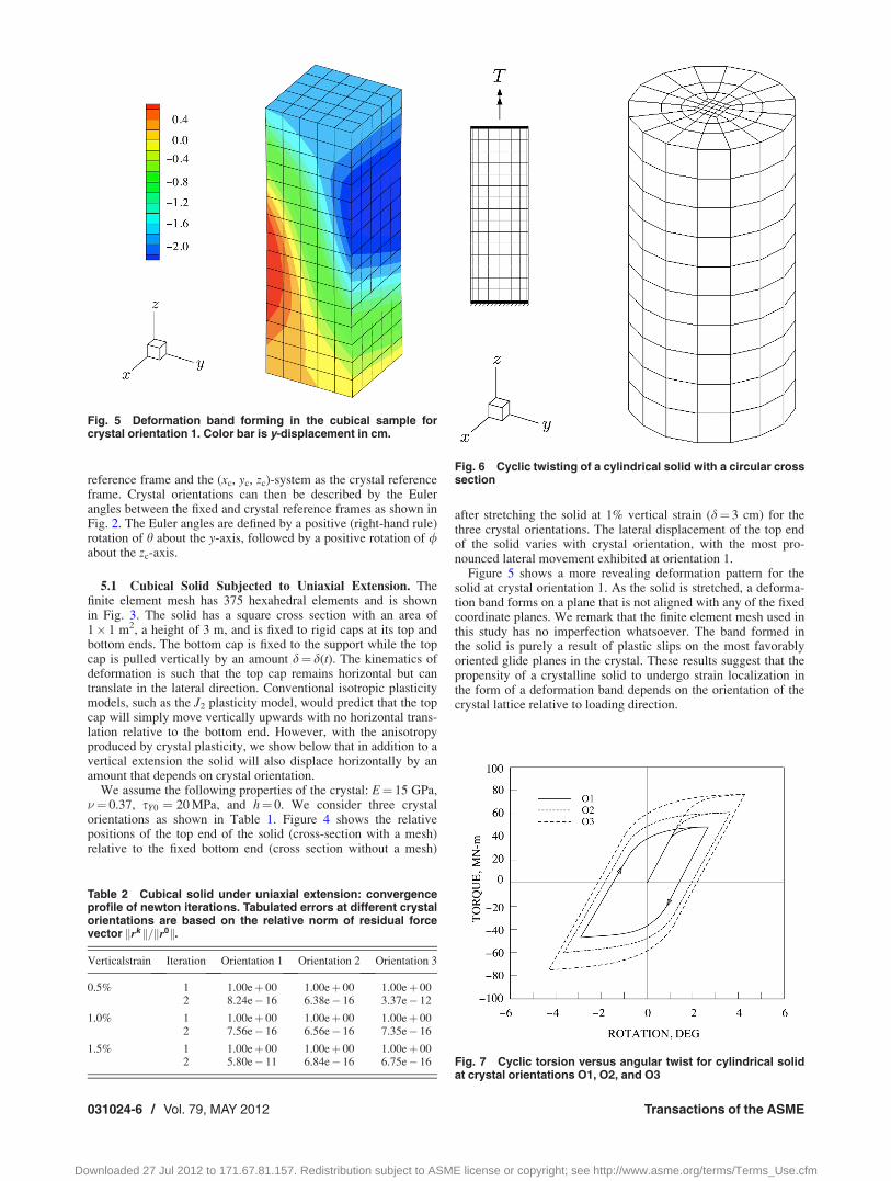
Figure 5 shows a more revealing deformation pattern for thesolid at crystal orientation 1. As the solid is stretched, a deforma-tion band forms on a plane that is not aligned with any of the fixedcoordinate planes. We remark that the finite element mesh used inthis study has no imperfection whatsoever. The band formed inthe solid is purely a result of plastic slips on the most favorablyoriented glide planes in the crystal. These results suggest that thepropensity of a crystalline solid to undergo strain localization inthe form of a deformation band depends on the orientation of thecrystal lattice relative to loading direction.
Fig. 5 Deformation band forming in the cubical sample forcrystal orientation 1. Color bar is y-displacement in cm.
Table 2 Cubical solid under uniaxial extension: convergenceprofile of newton iterations. Tabulated errors at different crystalorientations are based on the relative norm of residual forcevector krk k=kr0k.
Verticalstrain Iteration Orientation 1 Orientation 2 Orientation 3
0.5% 1 1.00eþ 00 1.00eþ 00 1.00eþ 002 8.24e� 16 6.38e� 16 3.37e� 12
1.0% 1 1.00eþ 00 1.00eþ 00 1.00eþ 002 7.56e� 16 6.56e� 16 7.35e� 16
1.5% 1 1.00eþ 00 1.00eþ 00 1.00eþ 002 5.80e� 11 6.84e� 16 6.75e� 16
Fig. 6 Cyclic twisting of a cylindrical solid with a circular crosssection
Fig. 7 Cyclic torsion versus angular twist for cylindrical solidat crystal orientations O1, O2, and O3
031024-6 / Vol. 79, MAY 2012 Transactions of the ASME
Downloaded 27 Jul 2012 to 171.67.81.157. Redistribution subject to ASME license or copyright; see http://www.asme.org/terms/Terms_Use.cfm

Table 2 shows the convergence profiles of global Newton itera-tions expressed in terms of the ratio of the relative norm of theglobal residual force vector. With very few exceptions (not shownin this table), the global iterations needed no more than two itera-tions to achieve convergence to machine precision. As noted ear-lier, the problem becomes a linear one as soon as the active slipsare identified, and in this example it took two iterations to identifythese active slip systems.
5.2 Cylindrical Solid Subjected to Cyclic Twisting. In thisexample, we apply one full cycle of torsion on a cylindrical solid,modeled with 640 hexahedral finite elements shown in Fig. 6. Thesolid is fixed at the bottom, and the top is attached to a rigid cap
on which two horizontal eccentric forces equal in magnitude butopposite in direction are applied. The rigidity of the cap preventsthe top surface from warping but does not inhibit it from translat-ing in any direction. As in the previous example, we test three dif-ferent crystal orientations summarized in Table 1. The crystals areassumed to have the same material parameters as in the previousexample.
Fig. 8 Lateral and vertical movement of top end (cross-sectionwith a mesh) relative to bottom end (cross-section without amesh) at different crystal orientations. Lateral displacementsmagnified 80 3. Crystal orientation 3 produced pure twistingwith no rocking.
Table 3 Cylindrical solid under cyclic torsion: convergenceprofile of newton iterations. Tabulated errors at different crystalorientations are based on the relative norm of residual forcevector krk k=kr0k.
Torque Iteration Orientation 1 Orientation 2 Orientation 3
Tmax 1 1.00eþ 00 1.00eþ 00 1.00eþ 002 6.30e� 01 6.63e� 01 6.21e� 013 5.98e� 09 1.00e� 08 3.60e� 014 — 9.85e� 09 5.62e� 09
0 1 1.00eþ 00 1.00eþ 00 1.00eþ 002 1.28e� 09 1.28e� 09 1.38e� 09
�Tmax 1 1.00eþ 00 1.00eþ 00 1.00eþ 002 6.10e� 01 5.60e� 01 6.86e� 013 8.65e� 04 9.12e� 09 5.23e� 094 2.36e� 05 — —5 6.44e� 076 6.12e� 09
0 1 1.00eþ 00 1.00eþ 00 1.00eþ 002 1.28e� 09 1.32e� 09 1.82e� 09
Fig. 9 Finite element mesh for a hollow cylinder subjected totorsional twisting. The cylinder has a height of 4 m, outer diam-eter of 2 m, and thickness of 0.1 m. The mesh has 5148 nodesand 2560 eight-node hexahedral elements, all integrated withthe B-bar option.
Fig. 10 Deformation bands forming in the hollow cylinder sub-jected to torsional twisting: (a) uniform crystal orientation 3 and(b) crystal orientation 3 with an imperfection in the form of crys-tal orientation 1 in four adjacent elements. Color bar is secondinvariant of deviatoric plastic strain in percent.
Journal of Applied Mechanics MAY 2012, Vol. 79 / 031024-7
Downloaded 27 Jul 2012 to 171.67.81.157. Redistribution subject to ASME license or copyright; see http://www.asme.org/terms/Terms_Use.cfm

Figure 7 shows the hysteretic torque-rotation curves generatedfor the three crystal orientations. The torque was increased to itsmaximum value so that the structure would yield everywhere. Thelimit load was then determined from the last convergent step. Wesee from Fig. 7 that the ultimate loads, 6Tmax, vary with crystalorientation and is highest for orientation 3, where the crystal axesare aligned to the coordinate axes. All hysteretic loops close, asto be expected from an elastic-perfectly plastic constitutiveresponse.
Figure 8 shows the lateral and vertical movements of the topend of the solid when the torque reaches the value Tmax during theinitial part of loading. We see that for crystal orientations 1 and 2,the top end of the cylinder translated laterally and vertically rela-tive to the fixed bottom base in such as way as to define a rockingmode. This is because for these two orientations, the crystal slipdirections are not aligned with the direction of twisting. In con-trast, no rocking mode can be seen for crystal orientation 3, wherethe crystal axes are aligned with the coordinate axes and, hence,with the sense of twisting.
Table 3 summarizes the convergence profiles of Newton itera-tions at various stages of loading. All iterations below the limitloads are superconvergent, i.e., the errors dropped immediately tozero once the active systems have been found, with the exceptionof the load steps near the limit loads designated as 6Tmax in thistable. We recall that load steps near the limit load are most diffi-cult to converge because they are close to the plateau of thetorque-twist curve where the slope is flat and where the load can-not be increased further. This is exemplified by the convergencerate at �Tmax for orientation 1, which is not quadratic. This is nota shortcoming of the iterative algorithm, but rather, it simplyreflects the proximity of the solution to a physically unstable state.
5.3 Twisting of a Hollow Cylinder. As a final example, weconsider a hollow cylinder shown in Fig. 9. The cylinder isclamped at both its top and bottom ends while the inner and outervertical faces are assumed to be traction-free. The top end is thentwisted while holding the bottom end fixed. Crystal orientation 3is assumed for the cylinder, with Young’s modulus E¼ 15 GPa,Poisson’s ratio �¼ 0.37, initial yield strength sY0 ¼ 10 MPa, andhardening parameter h¼�1 MPa (softening). Figure 10 showsthe resulting plastic strain contour after subjecting the cylinder toa final torsional twist of h¼ 1 deg. We see four vertical deforma-tion bands emerging from the imposed deformation. These bandsdid not form randomly, but rather, they are determined from thelattice orientation relative to direction of twisting. In a secondsimulation, a small imperfection is embedded in the cylinder byrotating the same crystal in four adjacent finite elements to orien-tation 1. The imperfection generates more intense localized defor-mation and a complementary deformation band propagating awayfrom the imperfection.
Table 4 shows the convergence profile of Newton iterations at50% and 100% of the total angle of twist. Observe that the itera-
tion of the solution is superconvergent for the case where the crys-tal is uniformly oriented, but the introduction of the imperfectioncauses the iteration to slow down a little bit. The latter may beattributed to difficulty in identifying the active slip systems in theneighborhood of the imperfection. However, Newton’s methodstill converged to machine precision after a few more iterations.
6 Summary and Conclusions
The ultimate algorithm for rate-independent crystal plasticityhas been implemented into a nonlinear finite element code foranalyzing the elasto-plastic deformation of 3D solids with poly-crystalline microstructures. Previous work has focused only on theperformance of the algorithm on the local stress-point level calcu-lations. The present work suggests that the algorithm performsequally well in the finite element simulations of the elasto-plasticdeformation of polycrystalline solids. The algorithm possesses thefollowing attributes that make it desirable to use in a finite ele-ment code: (a) it is locally exact for incremental strain applied asa ramp function, (b) it is unconditionally convergent on the locallevel since it does not perform a local iteration, and (c) it is as sta-ble as the widely used radial return algorithm for J2 plasticitywhen implemented globally in a finite element code. In addition,the global Newton iteration exhibits an optimal convergence ratethat is better than quadratic in some cases, implying that this itera-tive technique is just as effective for identifying the active con-straints in polycrystalline solids as it is for solving regularnonlinear problems.
Acknowledgment
This work is supported by the US Department of Energy GrantNo. DE-FG02-03ER15454 to Stanford University.
References[1] Nikolic, R. R., and Rice, J. R., 1988, “Dynamic Growth of Anti-Plane Shear
Cracks in Ideally Plastic Crystals,” Mech. Mater., 7, pp. 163–173.[2] Rice, J. R., 1987, “Tensile Crack Tip Fields in Elastic-Ideally Plastic Crystals,”
Mech. Mater., 6, pp. 317–335.[3] Rice, J. R., and Rosengren, G. F., 1968, “Plane Strain Deformation Near a Crack
Tip in a Power-Law Hardening Material,” J. Mech. Phys. Solids, 16, pp. 1–12.[4] Mandel, J., 1965, “Generalisation de la theorie de la plasticite de W.T. Koiter,”
Int. J. Solids Struct., 1, pp. 273–295.[5] Hill, R., 1966, “Generalized Constitutive Relations for Incremental Deforma-
tion of Metal Crystals by Multislip,” J. Mech. Phys. Solids, 14, pp. 95–102.[6] Maier, G. A., 1970, “Matrix Structural Theory of Piecewise Linear Elastoplas-
ticity With Interacting Yield Planes,” Meccanica, 5, pp. 54–66.[7] Rice, J. R., 1971, “Inelastic Constitutive Relations for Solids: An Internal Vari-
able Theory and its Application to Metal Plasticity,” J. Mech. Phys. Solids, 19,pp. 433–455.
[8] Hill, R., and Rice, J. R., 1972, “Constitutive Analysis of Elastic-Plastic Crystalsat Arbitrary Strain,” J. Mech. Phys. Solids, 20, pp. 401–413.
[9] Asaro, R. J., and Rice, J. R., 1977, “Strain Localization in Ductile SingleCrystals,” J. Mech. Phys. Solids, 25, pp. 309–338.
[10] Bishop, J. F. W., and Hill, R. A., 1951, “A Theory of the Plastic Distortion of aPolycrystal Aggregate Under Combined Stresses,” Philos. Mag., 42, pp. 414–427.
[11] Bishop, J. F. W., and Hill, R., 1941, “A Theoretical Derivation of the PlasticProperties of Polycrystalline Face-Centered Metal,” Philos. Mag., 42, pp.1298–1307.
[12] Lin, T. H., 1957, “Analysis of Elastic and Plastic Strains of a Face-CenteredCubic Crystal,” J. Mech. Phys. Solids, 5, pp. 143–149.
[13] Hutchinson, J. W., 1970, “Elastic-Plastic Behavior of Polycrystalline Metalsand Composites,” Proc. R. Soc. London, Ser. A, 319, pp. 247–272.
[14] Budiansky, B., and Wu, T. T., 1962, “Theoretical Prediction of Plastic Strainsof Polycrystals,” Proceedings of the Fourth U.S. National Congress on AppliedMechanics, R. M. Rosenberg, ed., ASME, New York, pp. 1175–1185.
[15] Iwakuma, T., and Nemat-Nasser, S., 1984, “Finite Elastic-Plastic Deformationof Polycrystalline Metals,” Proc. R. Soc. London, Ser. A, 394, pp. 87–119.
[16] Peirce, D., Asaro, R. J., and Needleman, A., 1982, “An Analysis of Uniform andLocalized Deformation in Ductile Single Crystals,” Acta Metall., 30, pp. 1087–1119.
[17] Kocks, U. F., 1970, “The Relation Between Polycrystal Deformation andSingle-Crystal Deformation,” Metall. Trans., 1, pp. 1121–1143.
[18] Kocks, U. F., and Canova, G. R., 1981, “How Many Slip Systems, andWhich?,” Deformation of Poly-Crystals: Mechanisms and Microstructures,Proceedings 2nd Riso International Symposium on Metallurgy and MaterialsScience, N. Hansen, A. Horsewell, T. Leffers, and H. Liholt, eds., Riso NationalLaboratory, Roskilde, Denmark, pp. 35–44.
Table 4 Twisting of a hollow cylinder: convergence profile ofnewton iterations. Tabulated errors at different crystal orienta-tions are based on the relative norm of residual force vectorkrk k=kr0k.
Percent twist Iteration Uniform Non-uniform
50% 1 1.00eþ 00 1.00eþ 002 2.29e� 15 2.13e� 103 — 3.08e� 16
100% 1 1.00eþ 00 1.00eþ 002 9.64e� 09 1.13e� 073 3.20e� 16 6.73e� 084 — 5.01e� 095 2.82e� 116 1.21e� 127 2.95e� 16
031024-8 / Vol. 79, MAY 2012 Transactions of the ASME
Downloaded 27 Jul 2012 to 171.67.81.157. Redistribution subject to ASME license or copyright; see http://www.asme.org/terms/Terms_Use.cfm

[19] Havner, K. S., 1982, “Minimum Plastic Work Selects the Highest SymmetryDeformation in Axially Loaded f.c.c. Crystals,” Mech. Mater., 1, pp. 97–111.
[20] Koiter, W. T., 1957, “Stress-Strain Relations, Uniqueness and Variational The-orems for Elastic-Plastic Materials With a Singular Yield Surface,” Q. Appl.Math., 11, pp. 350–354.
[21] Simo, J. C., Kennedy, J. G., and Govindjee, S., 1988, “Non-Smooth Multisur-face Plasticity and Viscoplasticity: Loading/Unloading Conditions and Numeri-cal Algorithms,” Int. J. Numer. Methods Eng., 26, pp. 2161–2185.
[22] Borja, R. I., and Wren, J. R., 1993, “Discrete Micromechanics of ElastoplasticCrystals,” Int. J. Numer. Methods Eng., 36, pp. 3815–3840.
[23] Cuitino, A. M., and Ortiz, M., 1992, “Computational Modelling of SingleCrystals,” Modell. Simul. Mater. Sci. Eng., 1, pp. 225–263.
[24] Steinmann, P., and Stein, E., 1996, “On the Numerical Treatment and Analysisof Finite Deformation Ductile Single Crystal Plasticity,” Comput. MethodsAppl. Mech. Eng., 129, pp. 235–254.
[25] Nemat-Nasser, S., and Obata, M., 1986, “Rate-Dependent Finite Elastic-PlasticDeformation of Polycrystals,” Proc. R. Soc. London, Ser. A, 407, pp. 343–375.
[26] Pan, J., and Rice, J. R., 1983, “Rate Sensitivity of Plastic Flow and Implicationsfor Yield Surface Vertices,” Int. J. Solids Struct., 19, pp. 973–987.
[27] Dumoulin, S., Hopperstad, O. S., and Berstad, T., 2009, “Investigation of Inte-gration Algorithms for Rate-Dependent Crystal Plasticity Using Explicit FiniteElement Codes,” Comput. Mater. Sci., 46, pp. 785–799.
[28] Ling, X., Horstemeyer, M. F., and Potirniche, G. P., 2005, “On the NumericalImplementation of 3D Rate-Dependent Single Crystal Plasticity Formulations,”Int. J. Numer. Methods Eng., 63, pp. 548–568.
[29] Anand, L., and Kothari, M. A., 1996, “Computational Procedure for Rate-Independent Crystal Plasticity,” J. Mech. Phys. Solids, 44, pp. 525–558.
[30] Schroder, J., and Miehe, C., 1997, “Aspects of Computational Rate-Independent Crystal Plasticity,” Comput. Mater. Sci., 9, pp. 168–176.
[31] Miehe, C., and Schroder, J. A., 2001, “Comparative Study of Stress UpdateAlgorithms for Rate-Independent and Rate-Dependent Crystal Plasticity,” Int.J. Numer. Methods Eng., 50, pp. 273–298.
[32] Busso, E., and Cailletaud, G., 2005, “On the Selection of Active Slip Systemsin Crystal Plasticity,” Int. J. Plast., 21, pp. 2212–2231.
[33] Wilkins, M. L., 1964, “Calculation of Elastic-Plastic Flow,” Methods of Com-putational Physics, Vol. 3, B. Alder, ed., Academic Press, New York.
[34] Borja, R. I., 2012, Plasticity Modeling and Computation, Springer-Verlag, Ber-lin, in press.
[35] Borja, R. I., 2008, “Assumed Enhanced Strain and the Extended Finite ElementMethods: A Unification of Concepts,” Comput, Methods Appl. Mech. Eng.,197, pp. 2789–2803.
[36] Borja, R. I., and Regueiro, R. A., 2001, “Strain Localization of Frictional Mate-rials Exhibiting Displacement Jumps,” Comput. Methods Appl. Mech. Eng.,190, pp. 2555–2580.
[37] Borja, R. I., 2000, “A Finite Element Model for Strain Localization Analysis ofStrongly Discontinuous Fields Based on Standard Galerkin Approximations,”Comput. Methods Appl. Mech. Eng., 190, pp. 1529–1549.
[38] Taylor, G. I., 1938, “Plastic Strain in Metals,” J. Inst. Met., 62, pp. 307–324.[39] Nowinski, J. L., 1981, Applications of Functional Analysis in Engineering,
Plenum Press, New York.
Journal of Applied Mechanics MAY 2012, Vol. 79 / 031024-9
Downloaded 27 Jul 2012 to 171.67.81.157. Redistribution subject to ASME license or copyright; see http://www.asme.org/terms/Terms_Use.cfm