comprehensive surveillance recording system - ctc u · 4.1.1. pattern tab control ... thank you for...
TRANSCRIPT
Network Video Recorder Comprehensive Surveillance Recording System
LEGAL The information in this publication has been carefully checked and is believed to be entirely accurate at the time of publication. CTC Union Technologies assumes no responsibility, however, for possible errors or omissions, or for any consequences resulting from the use of the information contained herein. CTC Union Technologies reserves the right to make changes in its products or product specifications with the intent to improve function or design at any time and without notice and is not required to update this documentation to reflect such changes. CTC Union Technologies makes no warranty, representation, or guarantee regarding the suitability of its products for any particular purpose, nor does CTC Union assume any liability arising out of the application or use of any product and specifically disclaims any and all liability, including without limitation any consequential or incidental damages. CTC Union products are not designed, intended, or authorized for use in systems or applications intended to support or sustain life, or for any other application in which the failure of the product could create a situation where personal injury or death may occur. Should the Buyer purchase or use a CTC Union product for any such unintended or unauthorized application, the Buyer shall indemnify and hold CTC Union Technologies and its officers, employees, subsidiaries, affiliates, and distributors harmless against all claims, costs, damages, expenses, and reasonable attorney fees arising out of, either directly or indirectly, any claim of personal injury or death that may be associated with such unintended or unauthorized use, even if such claim alleges that CTC Union Technologies was negligent regarding the design or manufacture of said product. TRADEMARKS Microsoft is a registered trademark of Microsoft Corp. HyperTerminal™ is a registered trademark of Hilgraeve Inc. User Manual Version 3.0 Oct 2009 This manual supports the following: Network Video Recorder Software Version 265 This document is the current official release manual. Please check CTC Union's website for any updated manual or contact us by E-mail at [email protected]. Please address any comments for improving this manual or to point out omissions or errors to [email protected]. Thank you. CTC Union maintains a support web site (support.ctcu.com) where you may obtain the latest manual, quick installation guide, and operational firmware. Membership to this web site is free, however, you must be a registered member in order to access any software updates.
CTC Union Technologies Co., Ltd.
2008~2009 Copyright, All rights reser

Table of Contents
1. INTRODUCTION ............................................................................................................................ 5
2. NVR SYSTEM INSTALLATION .................................................................................................. 6
2.1. SYSTEM REQUIREMENT................................................................................................................. 6 2.2. SOFTWARE INSTALL ...................................................................................................................... 6
2.2.1. Server V.S Client ............................................................................................................... 6
2.2.2. NVR Server Install ............................................................................................................ 7
2.2.3. NVR Client installation ................................................................................................... 12
2.3. START NVR SERVICE ................................................................................................................. 16
3. VIDEO STREAMING AND CHANNEL SETTING .................................................................. 18
3.1. RECORDING STORAGE SETUP....................................................................................................... 18 3.2. ADD A NEW CHANNEL .................................................................................................................. 19
3.2.1. Video setup...................................................................................................................... 21
3.2.2. Scheduled Recording setup ............................................................................................. 24
3.2.3. PTZ setup ........................................................................................................................ 26
3.3. LIVE VIEWING............................................................................................................................... 29
4. SYSTEM CONFIGURATION ..................................................................................................... 31
4.1. LAYOUT CONTROL ....................................................................................................................... 32 4.1.1. Pattern tab control .......................................................................................................... 32
4.2. USER CAMERA TREE ................................................................................................................... 34 4.2.1. Add/edit folders ............................................................................................................... 34
4.2.2. IO Port ............................................................................................................................ 35
4.3. SYSTEM CONTROL....................................................................................................................... 37 4.3.1. Synchronize all players ................................................................................................... 37
4.3.2. Logout ............................................................................................................................. 37
4.3.3. Calculator ....................................................................................................................... 37
4.3.4. Storage Map.................................................................................................................... 38
4.3.5. Confiuration system ........................................................................................................ 38
4.3.6. Configuration Cosole...................................................................................................... 39
4.3.7. Configuration Storage..................................................................................................... 43
4.3.8. Control Panel.................................................................................................................. 43
4.3.9. Add a new Channel ......................................................................................................... 43
4.4. SYSTEM BRIEFCASE VIEWER ....................................................................................................... 43

Table of Contents
4.4.1. LOG................................................................................................................................. 45
4.4.2. USER............................................................................................................................... 45
4.4.3. BKMK (Bookmark) ......................................................................................................... 48
4.4.4. MAP ................................................................................................................................ 48
4.4.5. SYS .................................................................................................................................. 48
4.4.6. ALL.................................................................................................................................. 48
4.4.7. Adding New Trigger Policy............................................................................................. 49
4.5. PLAYER CONFIGURATION............................................................................................................ 54 4.6. E-MAP CONFIGURATION ............................................................................................................... 54 4.7. SETUP FOR MULTI-MONITOR....................................................................................................... 58
5. NVR SYSTEM OPERATION ...................................................................................................... 60
5.1. LAYOUT CONTROL ....................................................................................................................... 60 5.2. USER TREE .................................................................................................................................. 61 5.3. SYSTEM CONTROL....................................................................................................................... 62
5.3.1. Sync. Play (Synchronize all players.).............................................................................. 62
5.3.2. Log out. ........................................................................................................................... 63
5.3.3. Calculator ....................................................................................................................... 63
5.3.4. Stg. Map (Storage report) ............................................................................................... 65
5.3.5. Cfg. System (Configure System)...................................................................................... 66
5.3.6. Cfg. Console (Configure Console).................................................................................. 67
5.3.7. Cfg. Storage (Configure Storage) ................................................................................... 68
5.3.8. Ctrl. Panel (Control Panel) ............................................................................................ 68
5.3.9. Add CH............................................................................................................................ 70
5.4. SYSTEM BRIEFCASE VIEWER ....................................................................................................... 70 5.4.1. LOG................................................................................................................................. 70
5.4.2. USER............................................................................................................................... 71
5.4.3. BKMK (Bookmark) ......................................................................................................... 71
5.4.4. MAP ................................................................................................................................ 71
5.4.5. SYS .................................................................................................................................. 72
5.4.6. ALL.................................................................................................................................. 72
5.5. PLAYER OPERATION .................................................................................................................... 73 5.6. VIEWING PLAYBACK VIDEO .......................................................................................................... 81 5.7. EXPORTING FOOTAGE ................................................................................................................. 84 5.8. EMAP OPERATION ....................................................................................................................... 85

Table of Contents
6. REMOTE LIVE VIEWING ........................................................................................................... 88
7. APPENDIX .................................................................................................................................... 94
7.1. CAMERA SUPPORTING MATRIX................................................................................................... 94

Chapter 1 Introduction
-5-
1. Introduction Thank you for purchasing the NVR surveillance system developed by CTC Union Technologies Company, Limited. CTC UNION NVR Server ™ is a surveillance system that delivers the most comprehensive security architecture for enterprise level security operation. NVR provides cost-effective scalability to support thousands of cameras and sensors. Its distributed management technology and modular architecture help reduce the total cost of ownership and streamline security operations for today's enterprise. For a better understanding, please read this manual before operating the NVR.

-6-
2. NVR System Installation
2.1. System requirement
Recommended System Requirement
Operating System Microsoft Windows XP
CPU Multi-core CPU
System Memory 2G (or more)
Graphics Nvidia or ATi Hi-performance graphics card
Video RAM 128MB (or more)
Required Space At least 40MB for installation
Other Requires DirectX 9
2.2. Software install
2.2.1. Server V.S Client
There are two software packages for NVR, one server, and one client. The server software
provides the main recording functions. It captures the video streams from the network
cameras, provides live view and records to local storage.
Client PCs view video from the server. A PC may simply use Internet Explorer web browser
to view video, or if using the client software, may local record streams from the server. The
client software cannot record the streams from the network cameras. That function is
reserved for the server.
The server requires a hardware dongle (USB HID) to run. The number of recording streams
depends on the software license purchased. The client software requires no dongle to
install, and any number of clients may be connected to the server.

-7-
2.2.2. NVR Server Install Locate the installation files. You may have these files on CDROM or they may have been downloaded from CTC Union's website. In either case, double-click the server install file. Administrative privileges are required in order to install this software. If you see the following message, either logout and log back in as 'administrator', log in with another account that has administrative privileges or add administrative privileges to your user account.

-8-
Continue with setup by clicking the 'Next >' button.
You must accept the License Agreement by selecting the radio button, then click 'Next >'.

-9-
Use the 'Browse…' button to select a different location to install the program, or press 'Next >' to continue.
Click 'Next >' to continue with the assigned program start folder.

-10-
Review the settings and then click 'Install'.
The setup now proceeds to install the program.

-11-
By default, just leave the three check boxes checked and then click 'Finish'.
The NVR has an icon that will reside in the toolbar. The icon is 'green' in color when the NVR is activated. To activate the NVR, right-click the toolbar icon and select 'Activate' from the pop-up window. If you select 'AutoStart' the NVR will automatically activate on Windows startup or login. In order to login through the console, the software lock device (HID USB dongle) must be found in the system. Otherwise, the user will be unable to login to the NVR.

-12-
2.2.3. NVR Client installation Locate the installation files. You may have these files on CDROM or they may have been downloaded from CTC Union's website. In either case, double-click the client install file.
Administrative privileges are required in order to install this software. If you see the following message, either logout and log back in as 'administrator', log in with another account that has administrative privileges or add administrative privileges to your user account.
Start to setup wizard
Continue with setup by clicking the 'Next >' button.

-13-
You must accept the License Agreement by selecting the radio button, then click 'Next >'.
Use the 'Browse…' button to select a different location to install the program, or press 'Next >' to continue.

-14-
Click 'Next >' to continue with the assigned program start folder.
Review the settings and then click 'Install'.

-15-
The setup now proceeds to install the program.
By default, just leave one check boxes checked and then click 'Finish'.

16-
2.3. Start NVR Service
At installation complete screen, you can choose "Start NVR service" to start the NVR
service. You can also invoke this by using "Start Menu"=>"Programs'=>" CTC Union NVR
V2.65"=>"Start NVR service
If the installation is properly done and service is started, you will see a gray triangle-shaped
icon in the tray-icon area (usually at the right-bottom side of the screen)
� Use the Tray Icon The NVR has an icon that will reside in the toolbar. The icon is 'green' in color when the NVR is activated. To activate the NVR, right-click the toolbar icon and select 'Activate' from the pop-up window. If you select 'AutoStart' the NVR will automatically activate on Windows startup or login. In order to login through the console, the software lock device (HID USB dongle) must be found in the system. Otherwise, the user will be unable to login to the NVR.
The color of the tray icon indicates the system status:
The NVR is offline.
The NVR is online.
The NVR will be auto-started very soon
The NVR is busy starting up or shutting down.
You can right-click on the tray-icon to change the system state:

17-
In production environment, you should configure your NVR as "Auto-start", so it will
automatically start on system start-up, and it will also automatically restart after abnormal
shutdown.
Right click the icon ,and click “Local Console” to login.
If there are no accounts existing in the system, an administrator account is automatically
created:
Default accounts
Account:admin
Password:1234
It is essential to change the password right after first login to ensure the security of
the system. Please refer to related pages in this s ection about how to perform
password change to a specific account.

18-
3. Video streaming and channel setting
3.1. Recording Storage Setup
If no directories have been enabled, this dialog will appear automatically after login. Click on the "Cfg. Storage". Following dialog box will appear. Storage Space Parameters
Parameter Description
Enabled Is the directory enabled?
MaxSize_GB Maximum space the recording process will utilize.
SafeFreeSize_GB Safe-guard of free space. If free space is lower than this value the
system will start to recollect space from old video data.
FileSize_MB The size of a single file.

19-
ReadCache_MB
This is the global setting of storage system read (playback) cache.
Adjust this value according to your available memory and required
performance.
WriteCache_MB
This is the global setting of storage system write (record) cache.
Adjust this value according to your available memory and required
performance.
3.2. Add a new channel
Right-click on the empty area of the user tree panel and then click "New Channel or click Add CH of the system control panel.
Following dialog box will appear.

20-
This is an integrated dialog with everything about channel configuration; camera setup, video setup, schedule recording setup, PTZ setup. Navigate through the tree nodes to change the items to be configured.Enter the channel name, IP address, etc information.
Note: "Channel name" is an important signature of a channel and therefore cannot
bechanged after it's created. Nor can it be duplicated with other channels. You should
choose the channel name carefully, as it associates all configuration and storage
information with that channel. If you expect a more user-friendly description, you can use
"Description" field for the purpose.
Camera parameter configuration
Parameter Description
Driver Choose deivce driver. Ex: DVS-8501E→CTCUnionDVS
EX:IPCAM-8318P→CTCUnionCam
Domain name: Domain name of the network camera
Description: Description of the network camera
IP Address IP address of the network camera
Port: The TCP/IP port number of the network camera
Channel : The channel number of the network camera. This value may apply if a
single video server has multiple channels.
Uncondition
Recording:
Check this box, if you wish the NVR to start recording immediately. To configure other types of recording, you need to perform additional operations after channel
Disable
Channel:
Temporarily disable the channel. NVR will not access any channel with
this box checked. You can always enable it at later time

21-
3.2.1. Video setup
Right-click on the desired channel and select "Video setup"
Following dialog box will appear.
Configuration Sets : Each channel can be associated with multiple set of configurations. A configuration set is composed of multiple parameters. A configuration set can also "inherit" from another configuration set.

22-
3.2.1.1. Record
Record parameter
Parameter Description
PreRecord Enter pre-record interval in seconds. Note this value requires
sufficient memory to work correctly
Activity
Interval
Maximum interval in seconds to consider two actives as one.
Note this value also serve the purpose of post-record interval.
ManualRecord
Minimum manual record interval. If two manual record are
requested within this interval, they are considered as an one
extended manual record request
PtzCtrlInterval Maximum interval seconds to consider two PTZ control activties
as one.
Activity Alarm Select alarm type for activity
Stereo Type Select stereo-type of camera
3.2.1.2. Video
StreamingMode Select streaming mode

23-
3.2.1.3. RTSP
Rtsp parameter
Parameter Description
RTSPPort Port number of RTSP
UrlPath Path part of the RTSP URL
MPEG4Framer Choice of internal framer for MPEG4
PacketLogging Choice of internal logging of transport packets
PacketBufSize Buffer size of receiving packet
RecoderThresh Packet recording time threshold. Unit: 1000000 means 1
secong
MPEG4Codec Choice of internal codec for MPEG4
StreamUseTCP Select to use TCP tunneling mode while streaming

24-
3.2.2. Scheduled Recording setup From power-on to power-off, it means NVR schedule recording works in PC
power-on to power-off.
Configuration
Scheduled configuration items has various types, including whole day, daily,
weekly (detailed), weekly (graphic), disabled. You may add multiple items.
Schedule recording parameter
Type Description
Whole day 24 hours recording
Daily Daily fixed interval . For example: daily 08:00:00 to
21:30:00.
Weekly (Detailed) Resembles "Daily", but you may appoint to days within a
week. For example: Every Monday, Wednesday, Friday

25-
08:00:00 to21:30:00
Weekly (Graphic) Weekly schedule. Each slot is united an hour.
Interval Fixed interval, each starts with offset every X seconds,
lasts Y seconds.
Disabled Disable current schedule item
Weekly (Graphic) Schedule Configuration
Horizontal axis is time, with hour as the unit. Vertical axis is day in a week. Click to
change the schedule status. Blue means enabled, white means disabled. Click any
cell and drag will copy the state of the clicked cells to others.
Configuration of schedule Details

26-
You may specified a Video Parameters for ach schedule configuration item .
When that item is activated during appropriate time, the specified parameter
will be used. If you choose (Default) for the value, schedule configuration
will not affect video parameters.
When multiple schedule configuration item is in effect, the higher (in order) one will
apply. To change the priority of the items, use Move Up and Move Down buttons
3.2.3. PTZ setup
Noted: Only for supportted PTZ Camera
Before you can use presets, you must first configure PTZ configuration. To invoke
the configuration dialog, click PTZ config in player context menu. If there's no PTZ
config item in the context menu, check the video config to see if the proper PTZ
type is selected. For more information, check Video Configuration

27-
The description can be renamed by clicking on its description. Click OK when you
done with configuration.
After PTZ is configured, you can use context menu of player to set or recall presets.
Or use keyboard 0-9 to recall when the player is focused.

28-
Patrol Patrol is a list of presets to be called in sequence. You can manage up to 10 patrols in the PTZ dialog.
Add to Patrol: To add a preset in the patrol, drag it from PresetList and drop it in
Patrol
Click the buttons (Delete, Move Up, Move Down) to remove or change the order of presets. Wait Seconds: The interval and speed of patrol can be set <NOTE> PTZ functionality is limited by the actual specs and SDK support of the hardware. Not all models support the functions mentioned above.

29-
3.3. Live viewing
Before viewing live video, a chanel must be attached to a player. To attach a channel, drag it from user tree (the red box above) to a player (the green area above). Or double click to auto assign it to an available player.
To switch from playback to live video, click LIVE (the left most)in the toolbar. Or when the

30-
player is focused, press ENTER on keyboard to view live video. Players can be focused by
left mouse click on it. You can tell if a player is focused by a green frame around it.
You can check the fourth small icon if it’s red.. It means system is recording.
For more detail, please refer Chapter 5. NVR System Operation.

31-
4. System Configuration
4.1
4.2
4.4
4.3
4.5

32-
4.1. Layout control
Switch between the pre-defined NxN or special layouts. For more System Operation details, please refer to 5.1 Layout control
4.1.1. Pattern tab control
User can create and rename tabs in pattern tab control. Each pattern tab has its own layout and state. Pattern-save functions Save pattern templates and pattern sets
Pattern set
Template

33-
Save as template
Save current page as a template. The template can be accessed in system briefcase viewer.
Save pattern set
Save all pages and their states as a pattern set.
Saved pattern sets are added to the frequently-used layout list in the local console. Click any pattern set to load. Current pattern layout will be overwrited. Exception If Reset pattern set on startup is enabled in console setting, the first in frequently-used layout is always loaded when local console is invoked.
For more System Operation details, please refer to 5.1 Layout control

34-
4.2. User Camera tree
User can manage objects by creating folders and dragging & dropping to change the hierarchy and the order. Folders can also be renamed. A quick reminder, the tree is global, so local changes effect all remote CTC NVR connected. The node "All channels" is pre-defined and cannot be modified. Dragging a channel in "All channels" to a user-created folder creates its representatives which can be operated like the original channel item. Deleting a representative does not remove the channel from the system.
4.2.1. Add/edit folders
To add a new folder, right-click on blank area and click Add a new folder
Add/edit folders
To add a new folder, right click on blank area of the User Tree and click on “Add a new folder”.
Right click on the new added folder, users can add a new folder under it, rename it, or

35-
remove it from the upper level tree.
To add a channel in user-created folder, drag a channel from folder “All channels” to the destined folder (Like the above red arrow).
4.2.2. IO Port
To access IO ports , expand a channel node in User Tree . Gray nodes are inactive ports. Red ones are active input. Green ones are active output. If a node is unexpandable, it doesn't support IO ports or it's not configured properly.
Control
To control IO ports, right click on it to access the mneu. Input ports cannot be controlled in the NVR system. They are connected to physical input devices such as switches, sensors... etc.
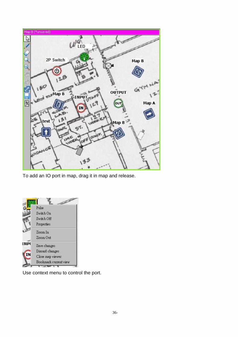
IO Ports in Maps
36-
To add an IO port in map, drag it in map and release.
Use context menu to control the port.

37-
The description and icon can be edited in the property dialog. The change is only applied to
the selected map item, not every item/node representing that port.
4.3. System control
Opens various configuration or tool dialogs.
4.3.1. Synchronize all players
Synchronize all players. When the button is sinked, playback control of all players are synchronized to the original recording time. For more System Operation details, please refer to 5.3 system control
4.3.2. Logout
Log out. The local console will be closed but the system is not terminated. You will need to enter account/password again to operate the system.
4.3.3. Calculator
For more Calculator Operation details, please refer Chapter 5.3

38-
4.3.4. Storage Map
For more Storage Operation details, please refer Chapter 5.3
4.3.5. Confiuration system
NVR provides a built-in web server to provide authorized and licensed remote user to view live video through Internet Explorer Open the system configuration dialog box
Active Locale Here you can select web server language
Web Server Listen Port
Here you can configure built-in web server listen TCP port
Default built-in web server listen port is 8086. If you configure the listen port to zero ("0"), the web server will be turned off
NVR Server Listen Port Here you can configure NVR server listen TCP port

39-
Attention: Used TCP Ports Please be noted that to make the remote live video web viewing, you are required to properly configure your firewall, if any. Two ports are needed. One is web server port, the other is NVR communication port, which defaults to 3557
4.3.6. Configuration Cosole
Primary Interface Settings Active Locale: CTCUnion NVR is designed as fully multilingual. Because of this, the factory default is set as English. You can change this by selecting "Cfg. Console Select the first combo-box to change to your locale After this, you need to restart the system to make the setting change take effective

40-
Console Style : Using large or small buttons Display Settings Aspect Mode: The video is not always fit perfectly in the player. It may be too wide or too tall. The player will display the video depends on this setting. Aspec Mode
Maintain aspect (Original size)
Stretch video (Stretch full frame)

41-
Crop to maintain aspect (Strech with original size, but it could cut some part of the picture.)
Processor Accelerating Enable Intel MMX, SSE, and SSE2 processor accelerating functions. 3 modes are available. Nearest neighbor has best performance and Cubic offers best graphics quality Processor Accelerating Option Disabled(Windows GDI) Originl
Nearest neighbor It offers best performance for PC.
Linear It offers more performance for PC and more graphics quality.
Cubic It offers best graphics quality
Compatible mode Disable all graphics aceclerating to solve display problems. The following are solutions for possible display problems. If the solution doesn't work, use Compatible mode.
Video card doesn't support DirectX 9 Replace the video card
DirectX is not installed Download DirectX 9 from Microsoft
The desktop color depth is not 32bit Click Properties in the context menu of desktop.In Settings tab, change color depth to 32bit.
32bit color depth is not available Update video card driver(check the manaul or CD provided by video card vendor)
※Use compatible mode only if any display problem is encountered.
Snapshot/Export Settings Currently only JPEG is supported. And the quality cannot be configured.
42-
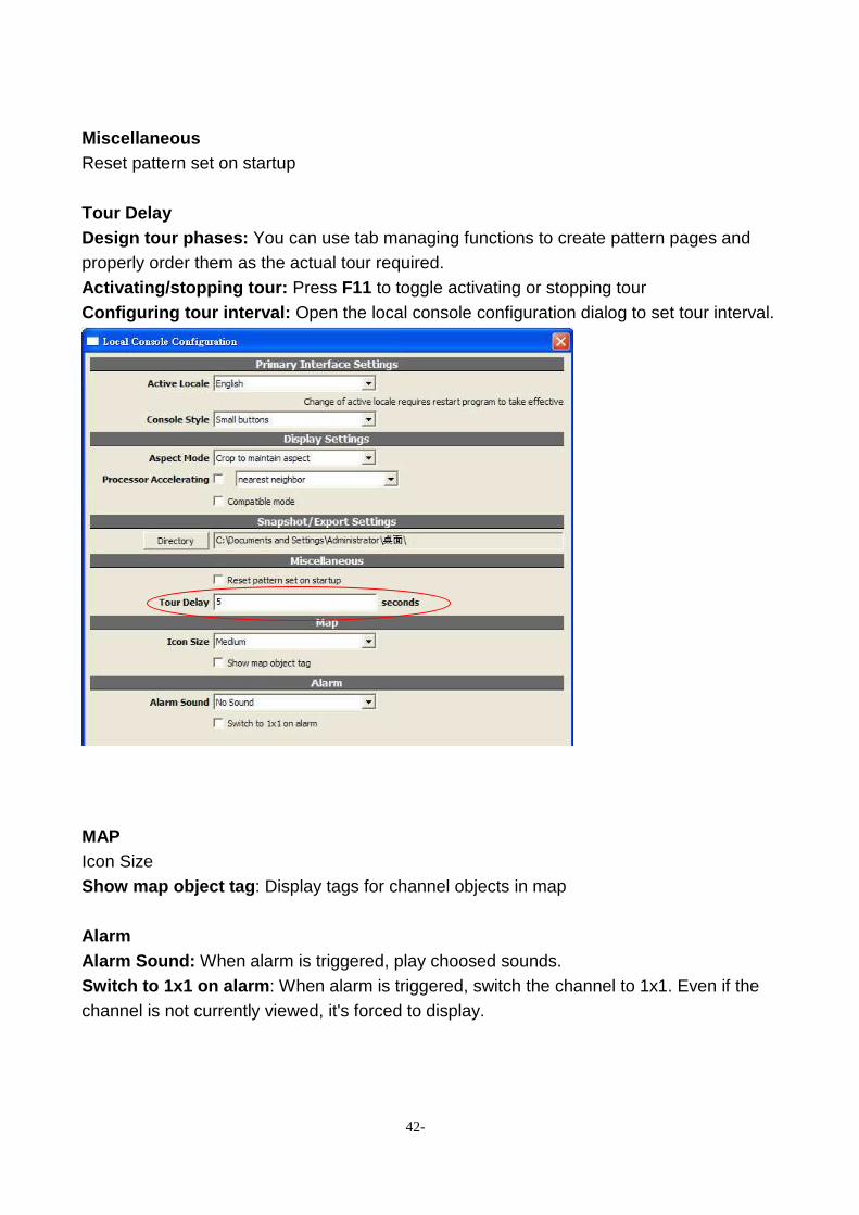
Miscellaneous Reset pattern set on startup Tour Delay Design tour phases: You can use tab managing functions to create pattern pages and properly order them as the actual tour required. Activating/stopping tour: Press F11 to toggle activating or stopping tour Configuring tour interval: Open the local console configuration dialog to set tour interval.
MAP Icon Size Show map object tag : Display tags for channel objects in map Alarm Alarm Sound: When alarm is triggered, play choosed sounds. Switch to 1x1 on alarm : When alarm is triggered, switch the channel to 1x1. Even if the channel is not currently viewed, it's forced to display.
43-
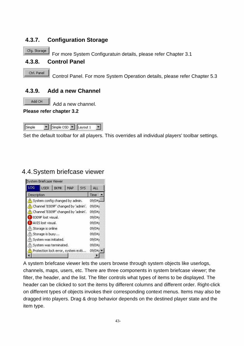
4.3.7. Configuration Storage
For more System Configuratuin details, please refer Chapter 3.1
4.3.8. Control Panel
Control Panel. For more System Operation details, please refer Chapter 5.3
4.3.9. Add a new Channel
Add a new channel. Please refer chapter 3.2
Set the default toolbar for all players. This overrides all individual players' toolbar settings.
4.4. System briefcase viewer
A system briefcase viewer lets the users browse through system objects like userlogs, channels, maps, users, etc. There are three components in system briefcase viewer; the filter, the header, and the list. The filter controls what types of items to be displayed. The header can be clicked to sort the items by different columns and different order. Right-click on different types of objects invokes their corresponding context menus. Items may also be dragged into players. Drag & drop behavior depends on the destined player state and the item type.

44-
Right Click on the empty area and following dialog box will appear.
Sub window under LOG viewer
New channel: Please refer Chapter 3.2 Add a new user: Please refer following setting. Add a new user group: Please refer following setting. Add new trigger policy: Please refer following setting. Upload file(s) to briefcase: Upload a image file for map backgroung. Add a new map: Add a map could editted

45-
4.4.1. LOG
Logs can be browsed in system briefcase viewer To make it easier to read, click on the tab to show certain types of items only
Right Click on the description item and following dialog box will appear.
Property: Show the item detail. Rename: Rename the item. Delete: Delete the item. Revert item setting: Restore the item setting. Revert channel change: Restore channel change.
4.4.2. USER
At the system briefcase, click the tab to "Users”. Following dialog box will appear.

46-
Right-click on the desired user or group and select "Property" to edit the settings of that item
Or right Click on the empty space of system briefcase viewer and select "add a new user ".
Following dialog box will appear.
You can check preview privilleges and select group privileges for the user.

47-
Right-click on empty space of system briefcase viewer and select "a new user group "
You can check the privillege you wish to grant to the group. Permission control overview The permission control in CTCUnion NVR is group-based. The administrator configures permissions for groups, and then assign the user to one or more groups. Permissions are not assigned directly to the user, but rather associates to the user through groups. Permission Types
System admin Allows to control system-level configuration, such as permissions or creating a channel.
System operation Allows creating or deleting a channel, editing maps and files.
All channel permissions Configures permissions to all channels.
Specific channel permissions Configures permissions to specific channels.
Channel live video Allows to view live video
Channel playback Allows accessing archived (playback) video.
Channel operation Allows to operate on PTZ, manual recording, or channel resetting.
Channel administration Allows to change settings.

48-
4.4.3. BKMK (Bookmark)
Users can review the Bookmark in this tab. Sort the Bookmark by clicking on “Description”, “Time”, and “Extra Info” for quick event review.
4.4.4. MAP
Please refer chapter 4.6
4.4.5. SYS
Users can review the System elements in this tab. Sort the elements by clicking on “Description”, “Time”, and “Extra Info” for quick event review. 4.4.6. ALL
Everything in the System Briefcase Viewer is shown together in this tab.

49-
4.4.7. Adding New Trigger Policy
Right-click on empty space of system briefcase viewer and select "A New trigger policy". If multiple trigger policies exists in a system, they are all in-effective.
Input Configuration
Channel trigger: Triggered by channel events such as video loss, alarm, IO port... etc.
System trigger: System events such as system start, system config change... etc
Schedule trigger: Triggered at specified time

50-
Output Configuration
Channel control: Recording, IO control, PTZ control
Email: Send Emails
FTP: Upload file to FTP server
Channel trigger
On IO on.
Off IO off
Vloss video loss
Vreturn video recovered
Disabled Channel disabled
Enabled Channel enabled
Record is/start recording
Nrecord not/stop recording
Alarm alarm triggered
alarm_progress alarm in progress
nalarm alarm dismissed
Schedule trigger Please refer Chapter 3.2.2 System trigger
any_vloss any video loss.
system_start system start
error_restart system start after error shut down
system_config_change system config changed
channel_config_change any channel config changed

51-
Channel control
Channel control parameter
CtrlChannel The channel to control
CtrlRecord Recording selection. Use 'record' to force record. Use 'nop' if no forcing recording is needed.
RecordDuration Number of seconds of forced recording.
CtrlIOPort IO port selection
CtrlIOValue Output control value
CameraPreset Move to preset

52-
Required parameters
SMTP.Server IP or domain name of SMTP server
SMTP.Port Port, usually 25
SMTP.User User name to log in
SMTP.Passwd Password to log in
Email.RCPT Recipients. At least one is required. Seperate multiple recipients with ';'.
Snapshot If "Email.Format" is set to "snapshot" and one or more channel control exist in this policy, a snapshot of the channels is attached to the email. Multiple channels will be composed as a single snapshot automatically. The dimension and quality of the snapshot can be configured in Snapshot Settings tab

53-
FTP
Required parameters
FTP.Server IP or domain name of FTP server
FTP.Port Port, usually 21
FTP.User User name to log in
FTP.Passwd Password to log in
Trigger policy logics Multiple trigger conditions can exist in a single trigger rule. Action is done only when all or some of the conditions are met, depends on AND or OR logic being applied. Logic OR is always applied to the first rule. Logic AND is applied to any added new rule.

54-
4.5. Player Configuration
There are three components in the player; status bar, display, and toolbar. Status bar shows the title of the channel attached and its states. The three indicators on the top-right show if the channel is recording (red), accessing recorded data (yellow), live video (green), or alarm. The toolbar is used to control the player. For more System Configuratuin details and please refer Chapter 5.5.
4.6. e-map configuration
Create New Map Select Add a new map in context menu of System briefcase viewer . The map can be draged into User tree and be operated as it is in system briefcase viewer . To view the map, drag it in a player Select Upload file(s) to briefcase in context menu of System briefcase viewer to upload a image file for map backgroung.

55-
MAP GUI viwer
Toolbar Functions
Icon Description
Enter map viewing mode
Enter map editing mode
Enter delete object mode
Zoom-in map
Restore 1:1 view of map
Map hyperlink
Save changed map

56-
Exit map editor
Adding Items Bitmap
Drag a JPEG/BMP file in the map. Or drag a previously uploaded file from system briefcase viewer
Channel Drag channels from system briefcase viewer or user tree
Hyperlink Assuming you want to add the link of map A in map B. 1. Open both map A and map B in players. 2. Adjust the view of map A with zoom in/out. 3. In the toolbar of map A, drag Map hyperlink icon to map B.
IO port Drag IO ports from system briefcase viewer or user tree. Basic Operations Zoom In Drag the magnifying glass cursor to select the rectangular area to
be viewed
Zoom Out The map is instantly zoomed out to 1:1 view.
Save changes Save changes Discard changes Restore the latest saved state. All unsaved changes will be lost. Close map viewer
Close map viewer
Bookmark current view
Added a bookmark of current map and current view in system briefcase .
Basic Operations of Objects Not all operations are available for all objects.
Reset aspect ratio
Reset the object to its original aspect. Only applies to Bitmaps.
Fit original size
Reset the object to its original size. Only applies to Bitmaps.
Arrange Arrange the object's display order(Z order). "Back" objects covered by

57-
"front" objects are not visible.
Set orientation
Set orientation of the object to 0/90/180/270 degrees.
Lock object Position/size/direction of a locked object cannot be changed. Its "property " dialog is still accessible if available for that object type.
Properties Invoke the property dialog to edit addtional information such as description or stereotype(icon). Only applies to hyperlink and IO port .
Remove object
Only the map object is deleted. The entity the object represents to will not be deleted.
Mouse operations
Rotate/resize
Move
Resize
Special operations Channel operation: Please refer chapter 3.2 IO port: Please refer chapter 4.2

58-
4.7. Setup for Multi-monitor Consoles and Profiles
A profile stores states and settings associated with a local console, including the window position, layout, saved login information, IP address of server... etc. To invoke a console with specific profile, click Connect to remote NVR in CTCUnion in Start Menu. Connection Agent dialog will be opened. To select a profile, use the Profile combo box
IP address of the remote server must be specified before connecting. If the server and console is on the same computer, enter 127.0.0.1 in IP address. Click Make Shortcut... button and a shortcut will be created in windows desktop. Simply double click on the shortcut and the console with this profile will be invoked. Rename the shortcut or it may be overwrited next time a shortcut is created.
Multi-monitor The following demostrates how to setup NVR for multi-monitor. The example uses 3 monitors but this can be applied to more or less monitors as well.

59-
1. Set the multi-monitor to Extended mode in Windows. This is not a requirement but it's
recommended for easier setup and more intuitive operations. In extended mode, multi-monitor act as a single desktop. Just navigate the mouse cursor in different monitors to access them. For more information, refer to the manual provided by video card vendor.
2. Create 3 shortcuts with different profiles. They may connect to the same NVR server or
different ones. Or they may connect to local host using 127.0.0.1 as IP address.
3. Invoke the consoles using the shortcuts. There will be 3 windows. Move them to the
monitors you want to place in and change the layout. To move among different monitors, simply move the mouse to the left/right edge of the monitor.
4. For best viewing experience, close menu of some consoles by pressing F10 on keyboard. 5. Next time the shortcuts are clicked, the consoles will be invoked as their last states and
layouts. The shortcuts can also be placed in the Startup of Windows Start Menu.

60-
5. NVR System Operation
5.1. Layout control
In CTCU NVR, a page is a set of players with its own layout settings and player states. Each page is configured separately and doesn't affect other pages. Users can create multiple pages and configure them for management purposes. For example, you can create a page named it "all channels". Switch its layout to 4x4 and attach 16 channels in it. And then create another page named "map". Switch it to 1x1 and open a map. Then you can switch between the two pages easily without open multiple windows or applications. Layout selection
Users can switch between the pre-defined NxN or special layouts depending on the actual demand.
All players show the live video
Stop all players
Show system information Add a new page
Click on the right tab button to where the black arrow is pointing to add a new page Editing pages

61-
Right click on the page use wants to edit. Here users can create, rename, duplicate, or close the tabs in pattern tab control. Each pattern tab has its own layout and state. Users can also drag the tab to change the order of the pages.
ToolBar
From left to right respectively:
• Toolbar type selector: Set the default toolbar for all players. This overrides all individual players' toolbar settings.
• OSD type selector: Select OSD information level for all players. • Main layout selector: Select default console layout type
For more Toolbar Operation setting details, please refer to chapter 5.5, 5.6 5.2. User tree
62-
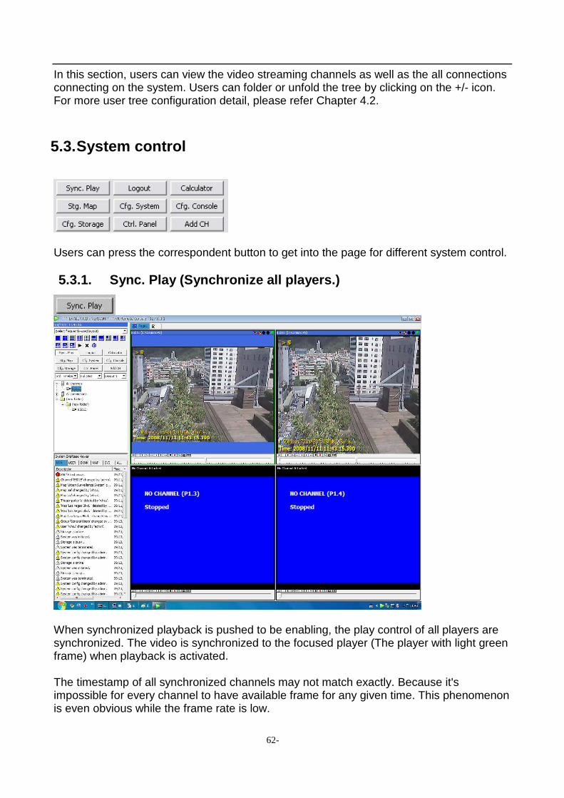
In this section, users can view the video streaming channels as well as the all connections connecting on the system. Users can folder or unfold the tree by clicking on the +/- icon. For more user tree configuration detail, please refer Chapter 4.2. 5.3. System control
Users can press the correspondent button to get into the page for different system control. 5.3.1. Sync. Play (Synchronize all players.)
When synchronized playback is pushed to be enabling, the play control of all players are synchronized. The video is synchronized to the focused player (The player with light green frame) when playback is activated. The timestamp of all synchronized channels may not match exactly. Because it's impossible for every channel to have available frame for any given time. This phenomenon is even obvious while the frame rate is low.

63-
5.3.2. Log out.
Log out. The local console will be closed but the system is not terminated. You will need to enter account/password to re-enter and operate the system. 5.3.3. Calculator
The Calculator helps you estimate the storage space capacity and optics viewing angle estimation under the user setting condition. Changing the parameters and users can expect to receive the correspondent numbers for reference. Storage Calculator Users can input any 3 of the 4 variables. And the checked field will be calculated using the parameters provided Optics Calculator For any calculation, sensor size and horizontal resolution of the camera must be provided. Please refer to the manufacturer's spec sheet of the camera. The user can provide 2 of the 3 variables; lens focal length, object distance, and horizontal coverage. The checked field will be calculated using the provided variables. Sensor size
Please refer to the spec sheet provided by the camera manufacturer

64-
Horizontal coverage
You can input lens focal length and object distance to let the system calculate the coverage, or vice versa Resolving power
110 lpm(horizontally)
50 lpm(horizontally) Resolving power is a measurement of how many details can be seen in real world. The more the resoving power is, the more easier to identify the object. It can be used as a reference to determine if something can be identified or read. For example, about 100 lpm(horizontally) minimal is required to read car license plates. However, the value is just for reference as there're other factors affecting image quality as well. For example, weather, shutter speed, and focusing
35M

65-
o Width of field of view(in meters)
i Sensor horizontal resolution(in pixels)
d Object distance(in meters)
f Focal length of lens(in mm)
i/o Resolving power(lpm, vertical)
5.3.4. Stg. Map (Storage report)

66-
By using the sub nodes of the root nodes, users can easily find and access recorded video in the scale of days, hours, or minutes. Users can sort the data by Data size or Data rate by selecting from the pull-down menu in the top of the window. Likewise, users can choose to display the data in List or Thumbnail by selecting from another pull-down menu. For viewing the searched image, double click on the searched data in the right frame and the image will show up in the player frame. Event viewing At right panel you can view the related events to the selected period of time. If you wish to examin the video of a specific event, you can either double-click the event to let an idle player to play it. Or that you can drag it to a specific player to play it. Data size / data rate Through the selection of the combo-box you can also change between viewing data size and data rate Resetting After a long period of time of last query, or that the storage report stop refreshing latest data, you can click the "Reset" button to retrieve updated information. Intelligent Video Report If one has properly configured intelligent detection (for example: double-tripwire counting), you can see additional nodes below the All Channels node. Try to open it to see detailed intelligent video report. 5.3.5. Cfg. System (Configure System)

67-
Users can do the System Configuration setting in this section. For more System Configuration setting details, please refer to 4.3 System Control 5.3.6. Cfg. Console (Configure Console)
Users can do the Local Console Configuration setting in this section. For more Local Console Configuration setting details, please refer to 4.3 System Control.

68-
5.3.7. Cfg. Storage (Configure Storage)
Users can do the Recording Storage Setup setting in this section. For more Recording Storage Setup setting details, please refer to 4.3 System Control. 5.3.8. Ctrl. Panel (Control Panel)
Black buton: Funtion enabled Gray button: Function disabled
Users can control the video play function in this small control panel.

69-
Play Control cross reference table
Pause Step backward
Step forward
Fast backward 2x/4x/8x
Fast forward 2x/4x/8x
Backward playback
Forward playback
Live view Stop Manual recording Take snapshot Frame skip mode
View earliest recording data
Jump backwardly for 1 day
Jump backwardly for 6 hours
Jump backwardly for 1 hour
Jump backwardly for 10 minutes
Jump backwardly for 1 minute
Backwardly playback latest recorded data
Jump forwardly for 1 day
Jump forwardly for 6 hours
Jump forwardly for 1 hour
Jump forwardly for 10 minutes
Jump forwardly for 1 minute
PTZ Control cross reference table
Optical Zoom in Focus-Far Aperture Open Stop
Optical Zoom out Focus-Near Aperture Close
Please note that this control function is only available for video channels with PTZ support. Editing Regions Users can manage and configure the layers and intelligent detection functions in this
70-
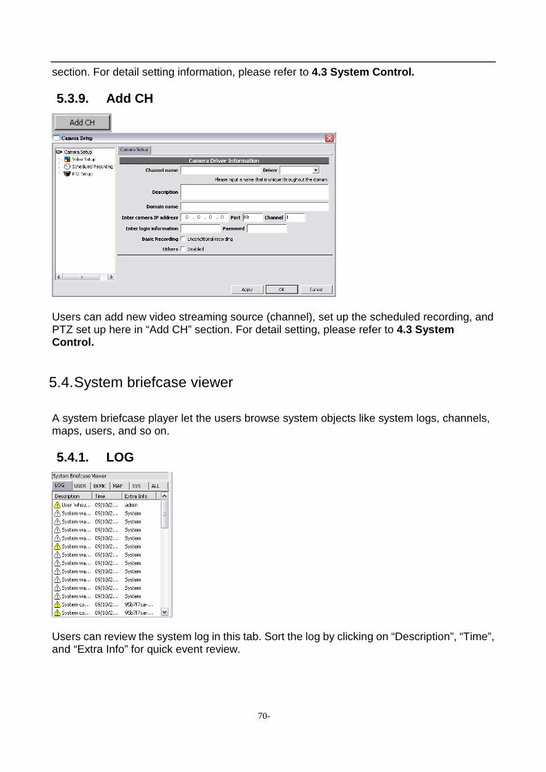
section. For detail setting information, please refer to 4.3 System Control. 5.3.9. Add CH
Users can add new video streaming source (channel), set up the scheduled recording, and PTZ set up here in “Add CH” section. For detail setting, please refer to 4.3 System Control.
5.4. System briefcase viewer
A system briefcase player let the users browse system objects like system logs, channels, maps, users, and so on. 5.4.1. LOG
Users can review the system log in this tab. Sort the log by clicking on “Description”, “Time”, and “Extra Info” for quick event review.

71-
5.4.2. USER
Users can review the system log in this tab. Right-clicking on the group/user, users can set up the properties of the group/user or delete it. For more detail setting, please refer to 4.3 System Control. 5.4.3. BKMK (Bookmark)
Users can review the Bookmark in this tab. Sort the Bookmark by clicking on “Description”, “Time”, and “Extra Info” for quick event review. 5.4.4. MAP

72-
Users can manage the surveillance system visual through a map or floor plan. For detail operation guide, please refer to 5.6 eMap operation. 5.4.5. SYS
Users can review the System elements in this tab. Sort the elements by clicking on “Description”, “Time”, and “Extra Info” for quick event review. 5.4.6. ALL
Everything in the System Briefcase Viewer is shown together in this tab.

73-
5.5. Player operation
GUI Overview
There are three components in the payer; status bar, display, and toolbar. Status bar shows the title of the channel attached and its states. The three indicators on the top-right shows if the channel is recording(red), accessing recorded data(yellow), live video(green), or alarm. The toolbar is used to control the player Title Displays the name and description of attached channel/map. The background color indicates the status
Channel live view
Map is loaded
Channel playback/Map is loading
Nothing is attached
LLIIVVEE
Title
Play state Indicator
OSD
Tool Bar
Time Bar
Status Indicator &
Avdnaced Function
Control
Play Control Indicator

74-
Map is changed and not saved
Blinking: Active alarm Static: Alarm in progress
Play state indicator
Live Live view
||< Pause, backward play
>|| Pause, forward play
< backward play
> forward play
<< Fast backward
>> Fast forward
E End of recorded data
AZ Actual size, zoomed
A Actual size
Z Zoomed
S Stretched
C Cropped
OSD Display the video time, resolution, and frame rate. Depends on OSD setting selected

75-
Toolbar In local console setting dialog , you can configure the size and style of the toolbar buttons Small buttons Large buttons
Live video
Pause Step Bkwd
Step Fwd
Fast Bkwd
Play Bkwd
Play Fwd
Fast Fwd
Stop Record Zoom SnapshotControl panel
Status indicator
Intelligent video Render audio Accessing disk Recording Video streaming
Rendering audio
In the context menu of players, click "Render audio" to enable audio. To mute the channel, just click it again. Or click on the speaker icon.

76-
Audio Icon Explained
The channel with sound is also in play
The channel with sound is not in play
The channel no sound is in play
The channel no sound is not in play
Taking snapshot

77-
To take a snapshot, click the camera button in the player toolbar. A message will be poped if the snapshot is taken Digital PTZ Control Step 1.Right-click and select Zoom-in
User can right-click the context menu and select "Zoom-In" to drag a rectangular area to zoom-in

78-
Step 2.Drag to select a rectangular area
Step 3.Zoomed-in.

79-
Under the zooming mode, user can hold mouse left button down to pan the zoomed area. User can also use mouse-wheel to easily zoom-in and zoom-out interested area quickly Player (Multi-Function-Display) Capabilities Each player slot in the console has an number as their identifier. Those are P1.1, P1.2.. P1.16, etc, as illstrated below. Their function is slightly different, as illustrated in the table following the picture.

80-
Player identifier Can play live & PlayBack? Can view maps?
P1.1 Yes Yes P1.2 Yes Yes P1.3 Yes Yes P1.4 Yes Yes
P1.5 ... P1.25 Yes No Splitter control Hover mouse on these areas and the cursor will be changed to a two-way arrow. Users can hold left button and drag to adjust the size of different console components.

81-
5.6. Viewing playback video
Concept There are several methods to view playback video. You can 1. Use the toolbar in player. It works just like the buttons on a CD/DVD player 2. Use player control panel 3. Use the timebar in player 4. Use the storage report 5. Hot keys Simple toolbar
Live view Pause Fast backward 2x/4x/8x Backward playback Forward playback Fast forward 2x/4x/8x Stop Manual recording Zoom in Take snapshot Open control panel Using playback timeline A timeline is an integrated tool for both inspecting recorded data and navigating in video playback. The timeline can be configured to show different information of recorded data. User can access the desired data easily based on the information the timeline provides

82-
Using timeline Timeline can be enabled in player context menu
Before timeline can be operated, it must acquire window focus first. To do so, left click on the timeline and a dotted box appeared around the timeline. The user can use the mouse wheel to zoom in or zoom out the timeline. The ruler indicates the scale. Basic operations
Drag on the ticks to navigate in the timeline (the cursor changes to four-way arrow before you can do this). Use mouse wheel to zoom in/out. The ticks change automatically depends on the scale. You can also hover on the timeline to see the exact time There're four types of ticks. The black thin lines are for seconds. Black thick ones are for minutes. Red thin lines are for hours. Red boxes are for days
You can also select an interval by mouse dragging in the trackbar area. The interval length

83-
will be displayed
Fast navigation are also available in context menu. Playback
You can double click on anywhere in trackbar area of the timeline to jump to that time point, or drag the arrow Timeline modes There are various modes in timeline to display different information. It can be set by right click on the timeline
Standard
Blue area indicates that there are recorded data. White area means there's no recorded data.
Storage level
Green blocks indicates the storage level of recorded data. This is the average of a fixed timespan, which depends on the scale of the timeline. In this mode, user can calculate storage by selecting an interval.
Activity
The height of the orange block is the counts of activities in a fixed timespan, which depends on the scale of the timeline.
Event
Orange: activity Green: recording Purple: unexpected system off Gray: normal system off

84-
5.7. Exporting footage
Using timeline When a time interval is selected in timeline, export footage dialog can be invoked in its context menu to export the selected time interval
The dialog
Export parameter

85-
Field Description
Capture channels The left list are the channels to be exported and the right are the available channels. NVR support multi-channels exporting.
Start time Start time
End time End time
Format
XGV is CTCUnionNVR's proprietary format. Select AVI if you wish to play the video in other video players. No player is guranteed to be able to play the exported video as codec installed on a computer varies. For a list of audio/video codecs supported in AVI export, please refer APPENDIX.
Directory Choose a directory
Filename prefix Make a Filename
Max file size If the exported data exceed this limit, it's divided into multiple files. When using storage media with small space such as CDs or floopy disks, this must be set.
File numbering from
If exported data is to be divided using Max File Size, the files will be named as a serquence. You can also fix the length of the filename by setting the digits. For example: with 4 digits, the files will be named as prefix0001, prefix0002, prefix0003......
Current Status Indicates if the exporting is started, paused, or cancelled.
Progress Progress
5.8. eMap operation
For detail eMap setting, please refer to 4.6 System Control.
Drag the eMap from the System Briefcase Viewer to one of the null player for viewing the map.

86-
For a settled eMap, users can double click on the icon to get the real-time video streaming and change to other maps.
Please Note: Not all editions of software license has this feature enabled. Check with feature matrix for more details.
Double Click!

87-
5.7 Hot keys To enable hot keys, you must first focus on a player. To do so, left click on the player you want to operate. Basic operation PTZ

88-
6. Remote live viewing � Concept
NVR provides a web server to let user view live images via Internet Explorer. � System Configuration
If you set TCP port to ‘0’, and the web server will be closed. (default: 8086) � TCP Port Attention: If your network has a firewall system, you need to open two ports. One port is for web Server Service use (default:8086), and the other port is for NVR Server Connection (default: 3557) Use Internet Explorer Viewing

89
Open IE browser, and log on to the IP address as follows. http://<NVR Server IP> : <web server TCP port> Here is the Example: http://61.251.181.169:8006
Users will find immediately that there is a yellow bar in the top of the frame indicating a CTCU
ActiveX control is required to install.
Click on the yellow bar and choose “Install ActiveX Control” to allow the download.

90
After several seconds, depending on users internet condition, a dialog will show up to ask for
ActiveX installation confirmation. Please press “Install”.
After the ActiveX installation is completed, users will see a screen like above. At this stage users
can click on the “Connect” to get a quick video stream from the remote side NVR (like below).

91
For accessing the full remote console of the NVR, please click on “Click here for full-function
remote interface”, which is in the bottom of the frame.

92
After clicking on the full function remote interface, another CTCU ActiveX control installation
indication will show up. Please click on “Install ActiveX Control” to allow the download.
After several seconds, depending on users internet condition, a dialog will show up to ask for
ActiveX installation confirmation. Please press “Install”.

93
After several seconds, depending on users internet condition, the full remote console of the NVR
will pop-up and the users can control the NVR directly through IE browser!

94
7. APPENDIX
7.1. Camera Supporting Matrix
Vendor Connectivity Video Audio Compatible Models
Tested
CTCU UDP, RTSP RTSP RTSP
DVS-8504E
DVS-8501E
IPCAM-8309D
IPCAM-8318P
IPCAM-8318F
IPCAM-8309F
IPCAM-8309FW
IPCAM-8318IR
IPCAM-8308IR
AXIS RTSP RTSP RTSP 209FD, 214, 211M,
241Q, Q7401
IQinVision HTTP M-JPEG --- IQ755, IQ753
ACTi SDK-10000 MPEG-4 PCM ACD-2200, ACM-1310N
VIVOTEK VNDP-080610
MPEG-4,
VV_H263,
M-JPEG
AAC, AMR
IP7135, PT3117, PZ6112,
PZ7151, FD7131, VS7100,
PZ6114, PT7135, IP7142,
FD6111, FD7131
ZAVIO RTSP, HTTP RTSP, MPEG-4,
M-JPEG,
RTSP,
G.711 F312A, F721A, F210A
SONY HTTP
MPEG-4,
M-JPEG,
H.264
G.711,
G.726
SNC-RZ50N, RZ30, P5,
SNC-RX550
Arecont Vision AV2000 2.5.37 M-JPEG --- AV3130, AV5100
EtroVision EtroSDK 1.31 MPEG-4 --- VTC-460
JVC
V.Networks HTTP M-JPEG --- C30U, C625U, C655U
BOSCH
VideoJet HTTP M-JPEG --- VideoJet-10

95
RTSP Supporting Information
Supported Video Codecs MPEG-4, M-JPEG, H.264
Supported Audio Codecs G.711, AAC, AMR, G.726
Supported Streaming Modes UDP, TCP, HTTP
AVI-Export Supporting Information
Supported Video Codecs MPEG-4, M-JPEG, H.264
Supported Audio Codecs G.711, PCM

96
CTC Union Technologies Co., Ltd.
Far Eastern Vienna Technology Center (Neihu Technology Park) 8F, No.60, Zhouzi Street Neihu District, Taipei 114, Taiwan