comprehensive product guide - wec group · comprehensive product guide . when quality, delivery,...
TRANSCRIPT

comprehensive product guide
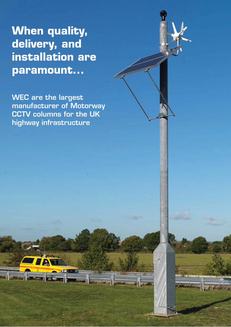
When quality, delivery, and installation are paramount...
WEC are the largest manufacturer of MotorwayCCTV columns for the UK highway infrastructure
Company Overview
Fixed Towers and Tilt-Over Towers
Fixed Tubular and Tilt-Over Tubular Columns
Fixed Square and Tilt-Over Square Columns
Decorative and Lamp Post Style Columns
Fixed and Tilt-Over Cabinet Base
Anti-Ram and Vandal Resistant Columns
Trolley Poles
Wall Poles
Highway Structures
Cabinets
Accessories
Root Information
Miscellaneous - Card Reader / Access Posts
Product Gallery
Terms and Conditions & Credit Application Form
pages 5 - 6
pages 7 - 12
pages 13 - 18
pages 19 - 24
pages 25 - 30
pages 31 - 38
pages 39 - 42
pages 43 - 48
pages 49 - 52
pages 53 - 54
pages 55 - 56
pages 57 - 72
page 73
page 74
page 75 - 80
page 81 - 82
CCTV

Com
pany
Ove
rvie
w
Introduction
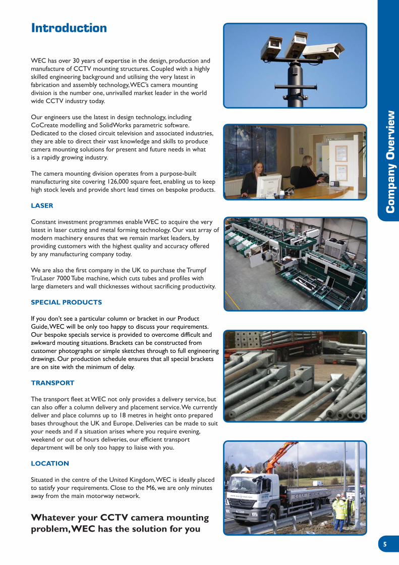
WEC has over 30 years of expertise in the design, production andmanufacture of CCTV mounting structures. Coupled with a highlyskilled engineering background and utilising the very latest infabrication and assembly technology, WEC’s camera mountingdivision is the number one, unrivalled market leader in the worldwide CCTV industry today.
Our engineers use the latest in design technology, includingCoCreate modelling and SolidWorks parametric software.Dedicated to the closed circuit television and associated industries,they are able to direct their vast knowledge and skills to producecamera mounting solutions for present and future needs in whatis a rapidly growing industry.
The camera mounting division operates from a purpose-builtmanufacturing site covering 126,000 square feet, enabling us to keephigh stock levels and provide short lead times on bespoke products.
LASER
Constant investment programmes enable WEC to acquire the verylatest in laser cutting and metal forming technology. Our vast array ofmodern machinery ensures that we remain market leaders, byproviding customers with the highest quality and accuracy offeredby any manufacturing company today.
We are also the first company in the UK to purchase the TrumpfTruLaser 7000 Tube machine, which cuts tubes and profiles withlarge diameters and wall thicknesses without sacrificing productivity.
SPECIAL PRODUCTS
If you don’t see a particular column or bracket in our ProductGuide, WEC will be only too happy to discuss your requirements.Our bespoke specials service is provided to overcome difficult andawkward mouting situations. Brackets can be constructed fromcustomer photographs or simple sketches through to full engineeringdrawings. Our production schedule ensures that all special bracketsare on site with the minimum of delay.
TRANSPORT
The transport fleet at WEC not only provides a delivery service, butcan also offer a column delivery and placement service. We currentlydeliver and place columns up to 18 metres in height onto preparedbases throughout the UK and Europe. Deliveries can be made to suityour needs and if a situation arises where you require evening,weekend or out of hours deliveries, our efficient transportdepartment will be only too happy to liaise with you.
LOCATION
Situated in the centre of the United Kingdom, WEC is ideally placedto satisfy your requirements. Close to the M6, we are only minutesaway from the main motorway network.
Whatever your CCTV camera mountingproblem, WEC has the solution for you

Com
pany
Ove
rvie
w
PAINTING
Using the latest airless spray techniques coupled with specialist vinylbased coatings, WEC are able to paint your CCTV columns and bracketsto any of the BS4800 and RAL colour ranges to suit your requirements.Powder coating facilities are also available on many of our standard andbespoke items.
SALES
Our helpful sales force, with an in-depth knowledge of our productsand the industry, ensure that WEC remain the number one choice forCCTV mounting equipment.
WEC offer full training on all of our products whether you are newto the industry or just looking for an update. One of our field salesengineers will pay you a visit to discuss your requirements.Alternatively, we have boardroom facilities for you to bring your clientsto discuss your particular project.
PRODUCTS
WEC are the largest manufacture of CCTV mounting structures inthe industry today. From simple fixed columns through to tilt-overlattice towers and motorised motorway columns and an endlessarray of brackets, we are sure that we can supply a cameramounting solution for your particular installation.
MAJOR INSTALLATIONS INCLUDE:
- Wembley Stadium- Transport for London Charging Scheme- Railtrack Upgrading- Dublin Port- Liverpool City Centre- Kuwait International Stadium- Belfast City Stadium- Birmingham Box ANPR Project- M42 Lane Sharing Scheme- Manchester Airport- Leeds City Centre- Drax Power Station North Yorkshire- National Grid Gas Storage Sites
ACCREDITATIONS
WEC are a BS EN ISO9001 and Link-Up approved company. Thisis your guarantee that goods and services are supplied to you atthe highest standards, right first time. Should you require structuralcalculations, these are available on many of our products, assuringyou a safe and stable support for your CCTV system.
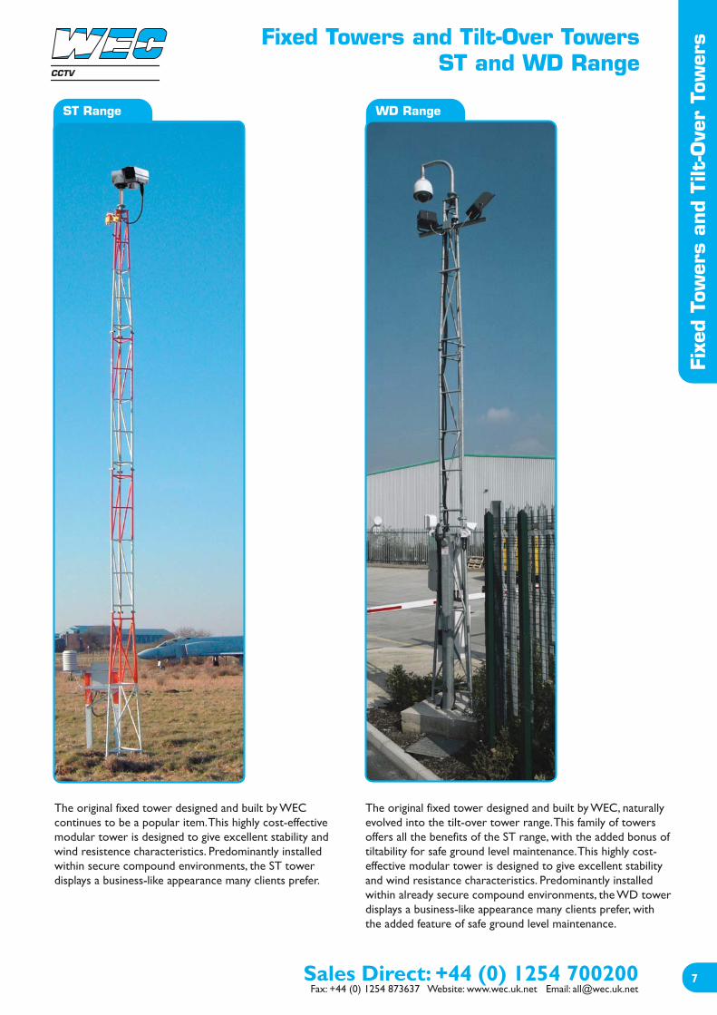
The original fixed tower designed and built by WECcontinues to be a popular item. This highly cost-effectivemodular tower is designed to give excellent stability andwind resistence characteristics. Predominantly installedwithin secure compound environments, the ST towerdisplays a business-like appearance many clients prefer.
The original fixed tower designed and built by WEC, naturallyevolved into the tilt-over tower range. This family of towersoffers all the benefits of the ST range, with the added bonus oftiltability for safe ground level maintenance. This highly cost-effective modular tower is designed to give excellent stabilityand wind resistance characteristics. Predominantly installedwithin already secure compound environments, the WD towerdisplays a business-like appearance many clients prefer, withthe added feature of safe ground level maintenance.
Fixed Towers and Tilt-Over TowersST and WD Range
Fixe
d To
wer
s an
d Tilt
-Ove
r To
wer
s
WD RangeST Range
CCTV

Fixed Towers and Tilt-Over TowersST and WD Range
Fixe
d To
wer
s an
d Tilt
-Ove
r To
wer
s
WD RangeST Range
Design Features- A cost-effective solution for achieving desired camera height.- Off the shelf heights up to 10 metres.- Rigid triangular lattice structure ensures excellent stability characteristics.- Modular construction for ease of transportation and erection.- Built in climbing rungs for ease of equipment maintenance.- Hot dipped galvanised finish for maximum weather protection and low maintenance requirements.- Custom modifications and towers tailored to the customer’s requirements.- Bespoke items in excess of 20 metres.
General Specifications- Standard pan and tilt fixing of 101.6 PCD.- Fixings included for telemetry receiver.- Built in cable entry and exit points.- Two metre sectional construction.- Equipment loading up to 25kg.- Buried root or flange-mounted versions available.- Standard heights available from 4 to 10 metres.- Compatible with WEC adaptors, accessories and anti-climbs.
Product CodesBuried root type:- ST4- ST6- ST8- ST10
Flange-mounted type:- ST4AF- ST6AF- ST8AF
(all ex-stock items)
Design Features- A cost-effective solution for achieving desired camera height.- The tilt-over tower enables camera maintenance at ground level.- An ideal installation where health & safety requirements are paramount.- Off the shelf heights up to 12 metres.- Maintenance and servicing easily and safely effected by one engineer.- Rigid triangular lattice structure ensures excellent stability characteristics.- Modular construction for ease of transportation and erection.- A transferable winch unit allows multi-site servicing and leaves installation tamper proof.- Hot dipped galvanised finish for maximum weather protection and low maintenance requirements.- Custom modifications and towers tailored to the customer’s requirements.- Heavy Duty versions now available
General Specifications- Standard pan and tilt fixing of 101.6 PCD.- Fixings included for telemetry receiver.- Built in cable entry and exit points.- Two metre sectional construction (3 metre on larger towers).- Equipment loading up to 25kg.- Buried root or flange-mounted versions available.- Standard heights available from 4 to 12 metres.- Compatible with WEC adaptors, accessories and anti-climbs.
Product CodesBuried root type:- WD4*- WD6*- WD8*- WD10*- WD10 HD - new!- WD12- WD12 HD - new!
Flange-mounted type:- WD4AF*- WD6AF*- WD8AF*- WD10AF
*Ex-stock items
New Product:! WD12 HD
CCTV
Best Seller! ST6 range
Static TowersST Range
Sta
tic
Tow
ers
Maximum equipment loadon all towers 25kg.
General Specification- Galvanized for maximum weather protection & low maintenance- Standard pan and tilt fixings of 101.6 PCD- Fixings included for telemetry receiver- Built in cable entry and exit points- Two and three metre sectional construction- Equipment loading of up to 25kg- Buried root or flange-mounted versions available- Heights available from 4 to 20 metres- Compatible with WEC adaptors and accessories
Standards Applicable- Structural Steelwork: BS EN 10210-1:1994, BS EN 10210-2:1997- General Steelwork: BS1449:1991, BS1387:1985, BS EN 10025:1993- Hot Dipped Galvanized: BS EN ISO 1461:2009- Welding Procedures: Comply with BS EN 1011-2:2001- Fasteners: Grade 8.8 BS3692:2001, BS4190:2001, DIN931, DIN934- Design Wind Loading: In accordance with CP3 chapter V Pt 2 & BS 6399 Pt 2:1997
Product Ref & Ordering Information
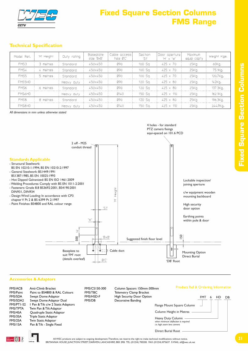
Technical Specification
Static Tower
Tower Height in Metres
Adaptor Flange
ST 8 AF
CCTV

CCTV
Static TowersST Range
Sta
tic
Tow
ers
Base and Windload Specification
Installation Method
1. From the map, select location of installation2. Excavate as per recommended area and depth3. Assemble root base as shown in fig. 14. Place cable duct in position, if required, and firmly secure5. Support root in the excavation using locally supplied timber or similar6. Ensure all three mounting pads are level and protruding 45mm to 50mm above finished concrete level7. Pour in concrete, ensuring a mix of C35 to table 6 BS 8110, tamp down and level surface8. Check that all three pads are still level and leave to cure for a minumum of 72 hours prior to erecting the tower
Technical Support
Our in-house design facility enables us to manufacture towers to anycustomer specification. The technical sales department will offer expertadvise on any exact requirements. Full training and instruction on theerection of towers, fixings, safe use and procedures is available on allWEC products. Project engineers, installation teams and serviceengineers, will all benefit from practical demonstrations, all of which canbe shown on our own test site facility.
Buried Root Type
Surface Mounted Type (STAF)
Concrete Foundation Table X x Y x Z
Adaptor plate for fixingtower to existing concrete
All three pads must be level and square
45-50
300
M24
Cable duct
For foundation sizesee chart
fig. 1
A minimum soil bearing pressure of 75 KN/m2 is assumed

Tilt-Over TowersWD Range
Tilt
-Ove
r To
wer
s
Maximum equipment loadon all towers 25kg.
Standards Applicable- Structural Steelwork: BS EN 10210-1:1994, BS EN 10210-2:1997- General Steelwork: BS1449:1991, BS1387:1985, BS EN 10025:1993- Hot Dipped Galvanized: BS EN ISO 1461:2009- Welding Procedures: Comply with BS5135:1984- Fasteners: Grade 8.8 BS3692:2001, BS4190:2001, DIN931, DIN934- Design Wind Loading: In accordance with CP3 chapter V Pt 2 & BS 6399 Pt 2:1997
General Specification- Galvanized for maximum weather protection & low maintenance- Standard pan and tilt fixings of 101.6 PCD- Fixings included for telemetry receiver- Built in cable entry and exit points- Two and three metre sectional construction- Equipment loading of up to 25kg- Buried root or flange-mounted versions available- Heights available from 4 to 12 metres- Compatible with WEC adaptors and accessories
Product Ref & Ordering Information
WD4 WD6 WD8WD10
Technical Specification
Safety NoticeIt is important that all operatives are familiar withall operating instructions and procedures.
Clear area beforelowering tower
1910
Transferable winch unit allows reduced cost inmulti-site servicing and secure installation.
WUA - Heavy dutyWUB - Light duty
Removable WinchesAlthough the WUA auto brake winch is initiallymore expensive, it has the versatility to cover therange of WEC products and has a quicker operatingaction.
Wind downTower height in metres
Adaptor flange
CCTV
Scan this code on your smartphone to access our Product Operating Instructions and Videos or please visit our website

Tilt
-Ove
r To
wer
sTilt-Over Towers
WD Range
Base and Windload Specification
Concrete Foundation Table X x Y x Z
Installation Method
1. From the map, select location of installation2. Excavate as per recommended area and depth3. Assemble root base as shown in fig. 14. Place cable duct in position, if required, and firmly secure5. Support root in the excavation using locally supplied timber or similar6. Ensure all three mounting pads are level and protruding 45mm to 50mm above finished concrete level7. Pour in concrete, ensuring a mix of C35 to table 6 BS 8110, tamp down and level surface8. Check that all three pads are still level and leave to cure for a minumum of 72 hours prior to erecting the tower
A minimum soil bearing pressure of 75 KN/m2 is assumed
Technical Support
Our in-house design facility enables us to manufacture towers to anycustomer specification. The technical sales department will offer expertadvise on any exact requirements. Full training and instruction on theerection of towers, fixings, safe use and procedures is available on allWEC products. Project engineers, installation teams and serviceengineers, will all benefit from practical demonstrations, all of which canbe shown on our own test site facility.
Buried Root Type (WD)
All three pads must be level and square
fig. 1
Adaptor FlangeMounted Type
Ensure mast is perpendicular tothe finished concrete level.
Cable duct
45-5
0
Foundation sizes are determined for three setsof wind speeds, which will cover most of theBritish Isles.
Area A = 44m/s (98mph)Area B = 48m/s (107mph)Area C = 52m/s (116mph)
Maximum gust speed is likely to be exceededon average once every 50 years at 10m abovethe ground in open level country.
CCTV
Fixed & Tilt-Over Tubular ColumnsFMT and TPT Range
Fixe
d &
Tilt
-Ove
r Tu
bula
r C
olum
ns
FMT Range
The highly popular FMT range offers an extremely cost-effective, unobtrusive and practical solution for manycamera mounting scenarios. This versatile tubular CCTVcolumn is supplied with a lockable access door and backboard for terminations. Suitable for installation inall areas, this range remains the specifiers preferredchoice for the cost-conscious.
The TPT range provides the ultimate in attractive,low maintenance, engineer friendly camera mountingsolutions. This CCTV column offers ease of installation,with the major benefit of safe ground level servicing.The TPT range is a robust version of the tilting column,featuring a square section lower post, with a tubularupper section. Suitable for mounting in low risk publicareas, the TPT range offers many practical engineeringbenefits, along with being unobtrusive and aestheticallypleasing.
TPT Range
CCTV

Fixed & Tilt-Over Tubular ColumnsFMT and TPT Range
Fixe
d &
Tilt
-Ove
r Tu
bula
r C
olum
ns
FMT Range TPT Range
Design Features- A cost-effective solution for achieving desired camera height.- Excellent stability characteristics for minimal camera movement.- Suitable for all public access areas.- A desirable column where aesthetics are of importance.- Flange-mounted ‘FM’ type root.- Direct buried column versions - ‘DB’.- ‘Pocket’ type roots available for restricted foundation locations.- Totally concealed cable management facility.- Hot dipped galvanised finish for maximum weather protection and low maintenance requirements.- Custom and bespoke versions tailored to the customer’s requirements.- Clamp on camera brackets available.
General Specifications- Standard pan and tilt fixing of 101.6 PCD.- Inspection/jointing aperture with backboards as standard.- Compatible with WEC adaptors, accessories and anti-climbs.- Equipment loading up to 25kg.- Variety of standard heights up to 12 metres.- Camera mount bracket adaptors available.- Heavy Duty versions now available
Product CodesTubular Columns:- FMT3*- FMT4*- FMT5*- FMT5 HD* - new!- FMT6*- FMT6 HD* - new!- FMT8*- FMT8 HD - new!- FMT10- FMT10 HD - new!- FMT12
*Ex-stock items
- DBT3- DBT4- DBT5- DBT6- DBT8- DBT10- DBT5HD- DBT6HD- DBT8HD- DBT10HD
Design Features- Solid and practical designs.- The tilt-over column enables camera maintenance at ground level.- Ideal installations where health & safety requirements are paramount.- Maintenance and servicing easily and safely effected by one engineer.- Rigid structure ensures excellent stability characteristics.- A transferable winch unit allows multi-site servicing and leaves installation tamper proof.- A desirable column where aesthetics are of importance.- Flange-mounted ‘FM’ type root.- ‘Pocket’ type roots available for restricted foundation locations.- Totally concealed cable management facility.- Hot dipped galvanised finish for maximum weather protection and low maintenance requirements.- Custom and bespoke versions tailored to the customer’s requirements.- Bespoke items available.
General Specifications- Standard pan and tilt fixing of 101.6 PCD.- Built in cable entry and exit points.- Compatible with WEC adaptors, accessories and anti-climbs.- Equipment loading up to 25kg.- Variety of standard heights from 4 to 10 metres.- Heavy Duty versions now available
Product CodesTubular Columns:- TPT4*- TPT5* - new!- TPT6*- TPT6 HD - new!- TPT8*- TPT8 HD - new!- TPT10
*Ex-stock items
CCTV
Best Seller! TPT6 rangeBest Seller! FMT6

Tubular ColumnsFMT Range
Technical Specification
Tubu
lar
Col
umns
Standards Applicable- Structural Steelwork: BS EN 10210-1:1994, BS EN 10210-2:1997- General Steelwork: BS1449:1991, BS1387:1985, BS EN 10025:1993- Hot Dipped Galvanized: BS EN ISO 1461:2009- Welding Procedures: Comply with BS EN 1011-2:2001- Fasteners: Grade 8.8 BS3692:2001, BS4190:2001 DIN931, DIN934- Design Wind Loading: In accordance with CP3 chapter V Pt 2 & BS 6399 Pt 2:1997- Paint Finishes: BS4800 and RAL colour range
Product Ref & Ordering Information
All dimensions in mm unless otherwise stated
2 off - M25conduit thread
4 holes - for standardPTZ camera fixingsequi-spaced on 101.6 PCD
Lockable inspection/joining aperture
c/w equipment woodenmounting backboard
High securitydoor option
Earthing pointswithin pole & door
Baseplate tosuit ‘FM’ root(details overleaf)
Cable duct
‘DB’ Root
Mounting OptionDirect Burial
Suggested finish floor level
500 15
0
Accessories & Adaptors
FMT/ACB Anti-Climb Bracket FMT/CS150-300 Column Spacers 150mm-300mmFMT/Paint Paint to BS4800 & RAL Colours FMT/TBC Telemetry Clamp BracketFMT/SDA Swept Dome Adaptor FMT/HSD-F High Security Door OptionFMT/SDA2 Swept Dome Adaptor Dual FMT/DB Decorative BandingFMT/PT1-S2 1 Pan & Tilt c/w 2 Static AdaptorsFMT/TPTA Twin Pan & Tilt Adaptor FMT/4SA Quadruple Static Adaptor FMT/3SA Triple Static AdaptorFMT/2SA Twin Static AdaptorFMT/1SA Pan & Tilt - Single Fixed
Flange Mount Tubular Column
Column Height in Metres
Heavy Duty Columnwhen minimum deflection is requiredi.e. high zoom lens camera
Direct Burial Root
FMT 6 HD DB
CCTV

Tubular ColumnsFMT Range
Tubu
lar
Col
umns
Base and Windload Specification
Concrete Foundation Table X x Y x Z
A minimum soil bearing pressure of 75 KN/m2 is assumed
Foundation sizes are determined for three setsof wind speeds, which will cover most of theBritish Isles.
Area A = 44m/s (98mph)Area B = 48m/s (107mph)Area C = 52m/s (116mph)
Maximum gust speed is likely to be exceededon average once every 50 years at 10m abovethe ground in open level country.
Installation Method
1. From the map, select location of installation2. Excavate as per recommended area and depth3. Assemble root base as shown in fig. 14. Insert root base into the hole ensuring that it is level and that the four studs protrude 60-70mm above the concrete foundation5. Fit the cable duct if routing via the interior of the column. A plastic pipe of approximately 100mm outside diameter is recommended for this. Ensure this protrudes through the template by 50mm (min).6. Pour concrete ensuring that it is a mix of C35 to table 6 BS 8110 and then tamp down well7. Fit the setting template over the four protruding studs, double-checking that they are level and that clear access can be gained to the cable duct if it is being used.8. Leave the concrete to cure for a minimum of 72 hours prior to attempting to erect the column9. When fitting the column, ensure that the concrete base is in complete contact with the underside of column and grout accordingly if required. Torque the nuts to 230-270 Nm (175-200 ft. lb.)10. When the column has been fitted, protect studs with a suitable protective coating. Denzo tape or similar is recommended for this.
All four studs mustbe level and square
fig. 1
Cable duct
Secure template to studsusing M24 nut top & bottomTemplate
M24studs
Anchorplate
FM Root (FM)
60-7
0
300-
330
450 Sq.
355 crs.
M24
50
FM Root Assembly
CCTV

Tilt-Over Tubular ColumnsTPT Range
Tilt
-Ove
r Tu
bula
r C
olum
ns
Technical Specification
Product Ref & Ordering Information
All dimensions in mm unless otherwise stated
4 holes - for standardPTZ camera fixingsequi-spaced on 101.6 PCD
Standards Applicable- Structural Steelwork: BS EN 10210-1:1994, BS EN 10210-2:1997- General Steelwork: BS1449:1991, BS1387:1985, BS EN 10025:1993- Hot Dipped Galvanized: BS EN ISO 1461:2009- Fasteners: Grade 8.8 BS3692:2001, BS4190:2001 DIN931, DIN934- Welding Procedures: Comply with BS EN 1011-2:2001- Design Wind Loading: In accordance with CP3 chapter V Pt 2 & BS 6399 Pt 2:1997- Paint Finishes: BS4800 and RAL colour range
TPT/WUA Heavy DutyTPT/WUB Light Duty
M25 conduitcable exit
TP6T
TP8T
TP10T
Lockable inspection/joining aperture
c/w equipment woodenmounting backboard
Earthing pointswithin pole & door
Baseplate to suit‘FM’ root(details overleaf)
Removablewinch WUB
Clear area beforelowering pole
Optional finish floor level
Cable duct
150
Removablewinch WUA
Accessories & Adaptors
TPT/ACB Anti-Climb Bracket TPT/CS150-300 Column Spacers 150mm-300mmTPT/Paint Paint to BS4800 & RAL Colours TPT/TBC Telemetry Clamp BracketTPT/SDA Swept Dome Adaptor TPT/HSD-F High Security Door OptionTPT/SDA2 Swept Dome Adaptor Dual TPT/DB Decorative BandingTPT/PT1-S2 1 Pan & Tilt c/w 2 Static AdaptorsTPT/TPTA Twin Pan & Tilt Adaptor TPT/3SA Triple Static AdaptorTPT/2SA Twin Static AdaptorTPT/1SA Pan & Tilt - Single Fixed
Removable WinchesAlthough the WUA auto brake winch is initiallymore expensive, it has the versatility to cover therange of WEC products and has a quickeroperating action.
Product (Tilt-Pole)
Pole Height in Metres
Section Tubular
Root (Direct Burial)
‘FM’ Root4-Stud Fixing
‘DB’ RootOptional
‘FM’ Root8-Stud Fixing
350
CCTV
Scan this code on your smartphone to access our Operating Instructions and Videos on our website!
TP5T
4 mtr.
5 mtr.
1150 120x120TP4T

Tilt-Over Tubular ColumnsTPT Range
Tilt
-Ove
r Tu
bula
r C
olum
ns
Base and Windload Specification
Foundation sizes are determined for three setsof wind speeds, which will cover most of theBritish Isles.
Area A = 44m/s (98mph)Area B = 48m/s (107mph)Area C = 52m/s (116mph)
Maximum gust speed is likely to be exceededon average once every 50 years at 10m abovethe ground in open level country.
Installation Method
1. From the map, select location of installation2. Excavate as per recommended area and depth3. Assemble root base as shown in fig. 14. Insert root base into the hole ensuring that it is level and that the four studs protrude 60-70mm above the concrete foundation5. Fit the cable duct if routing via the interior of the column. A plastic pipe of approximately 100mm outside diameter is recommended for this. Ensure this protrudes through the template by 50mm minimum.6. Pour concrete ensuring that it is a mix of C35 to table 6 BS 8110 and then tamp down well7. Fit the setting template over the four protruding studs, double-checking that they are level and that clear access can be gained to the cable duct if it is being used8. Leave the concrete to cure for a minumum of 72 hours prior to attempting to erect the column9. When fitting the column, ensure that the concrete base is in complete contact with the underside of the column and grout accordingly 10. When the column has been fitted, protect the studs with a suitable protective coating. Denzo tape or similar is recommend for this
Concrete Foundation Table X x Y x Z
A minimum soil bearing pressure of 75 KN/m2 is assumed
All four studs mustbe level and square
fig. 1
Cable duct
Secure template to studsusing M24 nut top & bottomTemplate
M24studs
Anchorplate
FM Root (FM)
60-7
0
300-
330
450 Sq.
355 crs.
M24
50
FM Root Assembly
4-hole fixing - up to 8m8-hole fixing - 10m
Additional holesfor 8-hole fixing
CCTV
Fixed & Tilt-Over Square Section ColumnsFMS and TPS Range
Fixe
d &
Tilt
-Ove
r Squa
re S
ecti
on C
olum
ns
FMS Range
The ever popular FMS square section range offers anextremely cost-effective, unobtruse practical solutionto many camera mounting scenarios. The versatilecolumns come complete with lockable access doors andbackboard for terminations. Suitable for installation in allareas, this range remains a favourite with specifiers andthe cost-conscious.
The TPS range provides undoubtedly one of the bestlow cost, low maintenance, engineer friendly cameramounting solutions. This CCTV column offers ease ofinstallation, with the major benefit of safe ground levelservicing. The TPS range is a light/medium duty versionof a tilting column, manufactured throughout from squaresection steel. Suitable for mounting in low risk publicareas, the TPS range offers many practical engineeringbenefits, along with being unobtrusive and aestheticallypleasing.
TPS Range
CCTV
Fixed & Tilt-Over Square Section ColumnsFMS and TPS Range
Fixe
d &
Tilt
-Ove
r Squa
re S
ecti
on C
olum
ns
FMS Range TPS Range
Design Features- A cost-effective solution for achieving desired camera height.- Excellent stability characteristics for minimal camera movement.- Suitable for all public access areas.- A desirable column where aesthetics are of importance.- Flange-mounted ‘FM’ type root.- Direct buried column versions - ‘DB’.- ‘Pocket’ type roots available for restricted foundation locations.- Totally concealed cable management facility.- Hot dipped galvanised finish for maximum weather protection and low maintenance requirements.- Custom and bespoke versions tailored to the customer’s requirements.- CCTV camera mounts available.- Heavy Duty versions now available
General Specifications- Standard pan and tilt fixing of 101.6 PCD.- Inspection/jointing aperture with backboards as standard.- Compatible with WEC adaptors, accessories and anti-climbs.- Equipment loading up to 25kg.- Variety of standard heights up to 8 metres.
Product CodesSquare Section Columns:- FMS3*- FMS4*- FMS5*- FMS5 HD - new!- FMS6*- FMS6 HD - new!- FMS8
*Ex-stock items
- DBS3- DBS4- DBS5- DBS6- DBS8
Design Features- Solid and practical designs.- The tilt-over column enables camera maintenance at ground level.- Ideal installation where health & safety requirements are paramount.- Maintenance and servicing easily and safely effected by one engineer.- Rigid structure ensures excellent stability characteristics.- A transferable winch unit allows multi-site servicing and leaves installation tamper proof.- A desirable column where aesthetics are of importance.- ‘Pocket’ type roots available for restricted foundation locations.- Totally concealed cable management facility.- Hot dipped galvanised finish for maximum weather protection and low maintenance requirements.- Custom and bespoke versions tailored to the customer’s requirements.- Bespoke items available.- Heavy Duty versions now available
General Specifications- Standard pan and tilt fixing of 101.6 PCD.- Built in cable entry and exit points.- Compatible with WEC adaptors, accessories and anti-climbs.- Equipment loading up to 25kg.- Variety of standard heights from 4 to 10 metres.
Product CodesTubular Columns:- TPS4*- TPS5* - new!- TPS6*- TPS6 HD - new!- TPS8*- TPS8 HD - new!- TPS10
*Ex-stock items
CCTV
New Stock Item! TPS5 Best Seller! FMS4
Fixed Square Section ColumnsFMS Range
Fixe
d Squa
re S
ecti
on C
olum
ns
Technical Specification
Standards Applicable- Structural Steelwork: BS EN 10210-1:1994, BS EN 10210-2:1997- General Steelwork: BS1449:1991 BS1387:1985, BS EN 10025:1993- Hot Dipped Galvanized: BS EN ISO 1461:2009- Welding Procedures: Comply with BS EN 1011-2:2001- Fasteners: Grade 8.8 BS3692:2001, BS4190:2001 DIN931, DIN934- Design Wind Loading: In accordance with CP3 chapter V Pt 2 & BS 6399 Pt 2:1997- Paint Finishes: BS4800 and RAL colour range
All dimensions in mm unless otherwise stated
2 off - M25conduit thread
4 holes - for standardPTZ camera fixingsequi-spaced on 101.6 PCD
Lockable inspection/joining aperture
c/w equipment woodenmounting backboard
High securitydoor option
Earthing pointswithin pole & door
Baseplate tosuit ‘FM’ root(details overleaf)
Cable duct
‘DB’ Root
Mounting OptionDirect Burial
Suggested finish floor level500 150
Accessories & Adaptors
FMS/ACB Anti-Climb Bracket FMS/CS150-300 Column Spacers 150mm-300mmFMS/Paint Paint to BS4800 & RAL Colours FMS/TBC Telemetry Clamp BracketFMS/SDA Swept Dome Adaptor FMS/HSD-F High Security Door OptionFMS/SDA2 Swept Dome Adaptor Dual FMS/DB Decorative BandingFMS/PT1-S2 1 Pan & Tilt c/w 2 Static AdaptorsFMS/TPTA Twin Pan & Tilt Adaptor FMS/4SA Quadruple Static Adaptor FMS/3SA Triple Static AdaptorFMS/2SA Twin Static AdaptorFMS/1SA Pan & Tilt - Single Fixed
Product Ref & Ordering Information
Flange Mount Square Column
Column Height in Metres
Heavy Duty Columnwhen minimum deflection is requiredi.e. high zoom lens camera
Direct Burial Root
FMT 6 HD DB
CCTV
Fixed Square Section ColumnsFMS Range
Fixe
d Squa
re S
ecti
on C
olum
ns
Base and Windload Specification
Foundation sizes are determined for three setsof wind speeds, which will cover most of theBritish Isles.
Area A = 44m/s (98mph)Area B = 48m/s (107mph)Area C = 52m/s (116mph)
Maximum gust speed is likely to be exceededon average once every 50 years at 10m abovethe ground in open level country.
Installation Method
1. From the map, select location of installation2. Excavate as per recommended area and depth3. Assemble root base as shown in fig. 14. Insert root base into the hole ensuring that it is level and that the four studs protrude 60-70mm above the concrete foundation5. Fit the cable duct if routing via the interior of the column. A plastic pipe of approximately 100mm outside diameter is recommended for this. Ensure this protrudes through the template by 50mm minimum.6. Pour concrete ensuring that it is a mix of C35 to table 6 BS 8110 and then tamp down well7. Fit the setting template over the four protruding studs, double-checking that they are level and that clear access can be gained to the cable duct if it is being used8. Leave the concrete to cure for a minumum of 72 hours prior to attempting to erect the column9. When fitting the column, ensure that the concrete base is in complete contact with the underside of the column and grout accordingly 10. When the column has been fitted, protect the studs with a suitable protective coating. Denzo tape or similar is recommend for this
Concrete Foundation Table X x Y x Z
A minimum soil bearing pressure of 75 KN/m2 is assumed
All studs must belevel and square
fig. 1
Cable duct
Secure template to studsusing M24 nut top & bottomTemplate
M24studs
Anchorplate
FM Root (FM)
60-7
0
300-
330
450 Sq.
355 crs.
M24
50
FM Root Assembly
4-hole fixing - up to 8m8-hole fixing - 10m
Additional holesfor 8-hole fixing
CCTV

Tilt-Over Square Section ColumnsTPS Range
Tilt
-Ove
r Squa
re S
ecti
on C
olum
ns
Technical Specification
Product Ref & Ordering Information
Standards Applicable- Structural Steelwork: BS EN 10210-1:1994, BS EN 10210-2:1997- General Steelwork: BS1449:1991 BS1387:1985, BS EN 10025:1993- Hot Dipped Galvanized: BS EN ISO 1461:2009- Welding Procedures: Comply with BS EN 1011-2:2001- Fasteners: Grade 8.8 BS3692:2001, BS4190:2001 DIN931, DIN934- Design Wind Loading: In accordance with CP3 chapter V Pt 2 & BS 6399 Pt 2:1997- Paint Finishes: BS4800 and RAL colour range
All dimensions in mm unless otherwise statedTPS/WUA Heavy DutyTPS/WUB Light Duty
M25 conduitcable exit
4 holes - for standardPTZ camera fixingsequi-spaced on 101.6 PCD
Lockable inspection/joining aperture
c/w equipment woodenmounting backboard
Earthing pointswithin pole & door
Baseplate tosuit ‘FM’ root(details overleaf)
Cable duct
150
350
Removablewinch WUB
Removablewinch WUA
Clear area beforelowering pole
Optional finish floor level
TP6S
TP8S
TP10S
‘FM’ Root4-Stud Fixing
‘DB’ RootOptional
‘FM’ Root8-Stud Fixing
Accessories & Adaptors
TPS/ACB Anti-Climb Bracket TPS/CS150-300 Column Spacers 150mm-300mmTPS/Paint Paint to BS4800 & RAL Colours TPS/TBC Telemetry Clamp BracketTPS/SDA Swept Dome Adaptor TPS/HSD-F High Security Door OptionTPS/SDA2 Swept Dome Adaptor Dual TPS/DB Decorative BandingTPS/PT1-S2 1 Pan & Tilt c/w 2 Static AdaptorsTPS/TPTA Twin Pan & Tilt Adaptor TPS/3SA Triple Static AdaptorTPS/2SA Twin Static AdaptorTPS/1SA Pan & Tilt - Single Fixed
Removable WinchesAlthough the WUA auto brake winch is initiallymore expensive, it has the versatility to cover therange of WEC products and has a quickeroperating action.
Product (Tilt-Pole)
Pole Height in Metres
Section Square
Root (Direct Burial)
TP 8 S DB
CCTV
Scan this code on your smartphone to access our Operating Instructions and Videos!

Tilt-Over Square Section ColumnsTPS Range
Tilt
-Ove
r Squa
re S
ecti
on C
olum
ns
Base and Windload Specification
Foundation sizes are determined for three setsof wind speeds, which will cover most of theBritish Isles.
Area A = 44m/s (98mph)Area B = 48m/s (107mph)Area C = 52m/s (116mph)
Maximum gust speed is likely to be exceededon average once every 50 years at 10m abovethe ground in open level country.
Installation Method
1. From the map, select location of installation2. Excavate as per recommended area and depth3. Assemble root base as shown in fig. 14. Insert root base into the hole ensuring that it is level and that the four studs protrude 60-70mm above the concrete foundation5. Fit the cable duct if routing via the interior of the column. A plastic pipe of approximately 100mm outside diameter is recommended for this. Ensure this protrudes through the template by 50mm minimum.6. Pour concrete ensuring that it is a mix of C35 to table 6 BS 8110 and then tamp down well7. Fit the setting template over the four protruding studs, double-checking that they are level and that clear access can be gained to the cable duct if it is being used8. Leave the concrete to cure for a minumum of 72 hours prior to attempting to erect the column9. When fitting the column, ensure that the concrete base is in complete contact with the underside of the column and grout accordingly. 10. When the column has been fitted, protect the studs with a suitable protective coating. Denzo tape or similar is recommend for this
Concrete Foundation Table X x Y x Z
A minimum soil bearing pressure of 75 KN/m2 is assumed
All studs must belevel and square
fig. 1
Cable duct
Secure template to studsusing M24 nut top & bottomTemplate
M24studs
Anchorplate
FM Root (FM)
60-7
0
300-
330
450 Sq.
355 crs.
M24
50
FM Root Assembly
4-hole fixing - up to 8m8-hole fixing - 10m
Additional holesfor 8-hole fixing
CCTV

Decorative and Lamp Post Style ColumnsFMV and LPS Range
FMV Range LPS Range
Dec
orat
ive
and
Lam
p Pos
t Sty
le C
olum
ns
The original and highly popular FMT tubular section range has, over a period of time, evolved into moredecorative and aesthetically pleasing versions. The FMV range is the modern day CCTV version of theVictorian gas light column and amongst its features are ornamental cast iron decorations to the base,shoulder and shaft. This ‘retro’ column is now the consultants and specifiers first choice for heritagesensitive applications. The sister column to the FMV is the LPS. This version of the FMT emulates thetraditional street lighting column, whereby the column has a larger circular base section, tapering intothe standard shaft. The base section, before tapering into the CCTV shaft, is larger than the normalstreetlight and has the ability to house control equipment.
CCTV

Decorative and Lamp Post Style ColumnsFMV and LPS Range
Dec
orat
ive
and
Lam
p Pos
t Sty
le C
olum
ns
FMV Range LPS Range
Design Features- Excellent stability characteristics for minimal camera movement.- Suitable for all public access areas.- Highly recommended for heritage sensitive applications.- Flange-mounted ‘FM’ type root.- ‘Pocket’ type roots available for restricted foundation locations.- Totally concealed cable management facility.- Hot dipped galvanised finish for maximum weather protection and low maintenance requirements.- Custom and bespoke versions tailored to the customer’s requirements.
General Specifications- Standard pan and tilt fixing of 101.6 PCD.- Inspection/jointing aperture with backboards as standard.- Compatible with WEC adaptors, accessories and anti-climbs.- Equipment loading up to 25kg.- Standard paint finished included on FMV columns.- Variety of standard heights up to 6 metres.
Product CodesVictorian Range:- FMV4- FMV5- FMV6
Design Features- Excellent stability characteristics for minimal camera movement.- A desirable column where aesthetics are of prime importance.- Suitable for all public access areas.- Flange-mounted ‘FM’ type root.- ‘Pocket’ type roots available for restricted foundation locations.- Heavy duty versions available.- Totally concelaed cable management facility.- Hot dipped galvanised finish for maximum weather protection and low maintenance requirements.- Custom and bespoke versions tailored to the customer’s requirements.
General Specifications- Standard pan and tilt fixing of 101.6 PCD.- Inspection/jointing aperture with backboards as standard.- Compatible with WEC adaptors, accessories and anti-climbs.- Equipment loading up to 25kg.- Variety of standard heights up to 10 metres.
Product CodesStreet Light Style Columns:- LPS4- LPS5- LPS6- LPS8- LPS10- LPS8HD- LPS10HD
CCTV
Various colours and finishes available! Also available in Stainless Steel!

Victorian ColumnsFMV Range
Vic
tori
an C
olum
ns
Product Ref & Ordering Information
Standards Applicable- Structural Steelwork: BS EN 10210-1:1994 BS EN 10210-2:1997- General Steelwork: BS1449:1991, BS1387:1985 BS EN 10025:1993- Hot Dipped Galvanized: BS EN ISO 1461:2009- Welding Procedures: Comply with BS EN 1011-2:2001- Fasteners: Grade 8.8 BS3692:2001 BS4190:2001, DIN931, DIN934- Design Wind Loading: In accordance with CP3 chapter V Pt 2 & BS 6399 Pt 2:1997- Paint Finishes: BS4800 and RAL colour range
Technical Specification
All dimensions in mm unless otherwise stated
4 holes - for standardPTZ camera fixingsequi-spaced on 101.6 PCD
2 off - M25conduit thread
Lockable inspection/joining aperture
c/w equipment woodenmounting backboard
High securitydoor option
Earthing pointswithin pole & door
‘SA’ SALISBURY ‘TU’ TURNER ‘WI’ WINDSOR
Baseplate tosuit ‘FM’ root
Baseplate tosuit ‘FM’ root(details overleaf)
Baseplate tosuit ‘TC’ root(details overleaf)
Cable duct
Finish floor level
150
Accessories & Adaptors
FMV/ACB Anti-Climb Bracket FMV/3SA Triple Static AdaptorFMV/Paint Paint to BS4800 & RAL Colours FMV/2SA Twin Static AdaptorFMV/SDA Swept Dome Adaptor FMV/1SA Pan & Tilt - Single FixedFMV/SDA2 Swept Dome Adaptor Dual FMV/CS150-300 Column Spacers 150mm-300mmFMV/PT1-S2 1 Pan & Tilt c/w 2 Static Adaptors FMV/TBC Telemetry Clamp BracketFMV/TPTA Twin Pan & Tilt Adaptor FMV/HSD-F High Security Door OptionFMV/4SA Quadruple Static Adaptor
Flange Mounted Baseplate
Range: Victorian
Model: Turner
Column Height in Metres
FM V TU 6
CCTV

Victorian ColumnsFMV Range
Vic
tori
an C
olum
ns
Base and Windload Specification
Concrete Foundation Table X x Y x Z
A minimum soil bearing pressure of 75 KN/m2 is assumed
Installation Method
1. From the map, select location of installation2. Excavate as per recommended area and depth3. Assemble root base as shown in fig. 14. Insert root base into the hole ensuring that it is level and that the four studs protrude 60-70mm above the concrete foundation5. Fit the cable duct if routing via the interior of the column. A plastic pipe of approximately 100mm outside diameter is recommended for this. Ensure this protrudes through the template by 50mm minimum.6. Pour concrete ensuring that it is a mix of C35 to table 6 BS 8110 and then tamp down well7. Fit the setting template over the four protruding studs, double-checking that they are level and that clear access can be gained to the cable duct if it is being used8. Leave the concrete to cure for a minumum of 72 hours prior to attempting to erect the column9. When fitting the column, ensure that the concrete base is in complete contact with the underside of the column and grout accordingly. 10. When the column has been fitted, protect the studs with a suitable protective coating. Denzo tape or similar is recommend for this
All studs mustbe level and square
fig. 1
Cable duct
Secure template to studsusing M24 nut top & bottom
Template
M24studs
Anchorplate
FM Root Assembly
300-
330
60-7
0
50
M24
‘FM’ 4 boltroot
‘FM’ 8 boltroot
355
crs.
450
Sq.
550
crs.
575
crs.
645
Sq.
CCTV
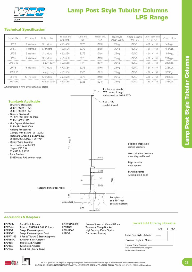
Lamp Post Style Tubular ColumnsLPS Range
Lam
p Pos
t Sty
le T
ubul
ar C
olum
ns
Standards Applicable- Structural Steelwork: BS EN 10210-1:1994 BS EN 10210-2:1997- General Steelwork: BS1449:1991, BS1387:1985 BS EN 10025:1993- Hot Dipped Galvanized: BS EN ISO 1461:2009- Welding Procedures: Comply with BS EN 1011-2:2001- Fasteners: Grade 8.8 BS3692:2001 BS4190:2001, DIN931, DIN934- Design Wind Loading: In accordance with CP3 chapter V Pt 2 & BS 6399 Pt 2:1997- Paint Finishes: BS4800 and RAL colour range
Product Ref & Ordering Information
Technical Specification
All dimensions in mm unless otherwise stated
2 off - M25conduit thread
4 holes - for standardPTZ camera fixingsequi-spaced on 101.6 PCD
Lockable inspection/joining aperture
c/w equipment woodenmounting backboard
High securitydoor option
Earthing pointswithin pole & door
Baseplate tosuit ‘FM’ root(details overleaf)
Cable duct
Suggested finish floor level
Accessories & Adaptors
LPS/ACB Anti-Climb Bracket LPS/CS150-300 Column Spacers 150mm-300mmLPS/Paint Paint to BS4800 & RAL Colours LPS/TBC Telemetry Clamp BracketLPS/SDA Swept Dome Adaptor LPS/HSD-F High Security Door OptionLPS/SDA2 Swept Dome Adaptor Dual LPS/DB Decorative BandingLPS/PT1-S2 1 Pan & Tilt c/w 2 Static AdaptorsLPS/TPTA Twin Pan & Tilt Adaptor LPS/3SA Triple Static AdaptorLPS/2SA Twin Static AdaptorLPS/1SA Pan & Tilt - Single Fixed
200
1610
LPS
Lamp Post Style - Tubular
Column Height in Metres
Heavy Duty Columnwhen minimum deflection is requiredi.e. high zoom lens camera
LPS 6 HD
CCTV

Lam
p Pos
t Sty
le T
ubul
ar C
olum
ns
Lamp Post Style Tubular ColumnsLPS Range
Base and Windload Specification
Foundation sizes are determined for three setsof wind speeds, which will cover most of theBritish Isles.
Area A = 44m/s (98mph)Area B = 48m/s (107mph)Area C = 52m/s (116mph)
Maximum gust speed is likely to be exceededon average once every 50 years at 10m abovethe ground in open level country.
Installation Method
1. From the map, select location of installation2. Excavate as per recommended area and depth3. Assemble root base as shown in fig. 14. Insert root base into the hole ensuring that it is level and that the four studs protrude 60-70mm above the concrete foundation5. Fit the cable duct if routing via the interior of the column. A plastic pipe of approximately 100mm outside diameter is recommended for this. Ensure this protrudes through the template by 50mm minimum.6. Pour concrete ensuring that it is a mix of C35 to table 6 BS 8110 and then tamp down well7. Fit the setting template over the four protruding studs, double-checking that they are level and that clear access can be gained to the cable duct if it is being used8. Leave the concrete to cure for a minumum of 72 hours prior to attempting to erect the column9. When fitting the column, ensure that the concrete base is in complete contact with the underside of the column and grout accordingly. 10. When the column has been fitted, protect the studs with a suitable protective coating. Denzo tape or similar is recommend for this
Concrete Foundation Table X x Y x Z
A minimum soil bearing pressure of 75 KN/m2 is assumed
All four studs mustbe level and square
fig. 1
Cable duct
Secure template to studsusing M24 nut top & bottomTemplate
M24studs
Anchorplate
FM Root (FM)
60-7
0
300-
330
450 Sq.
355 crs.
M24
50
FM Root Assembly
CCTV

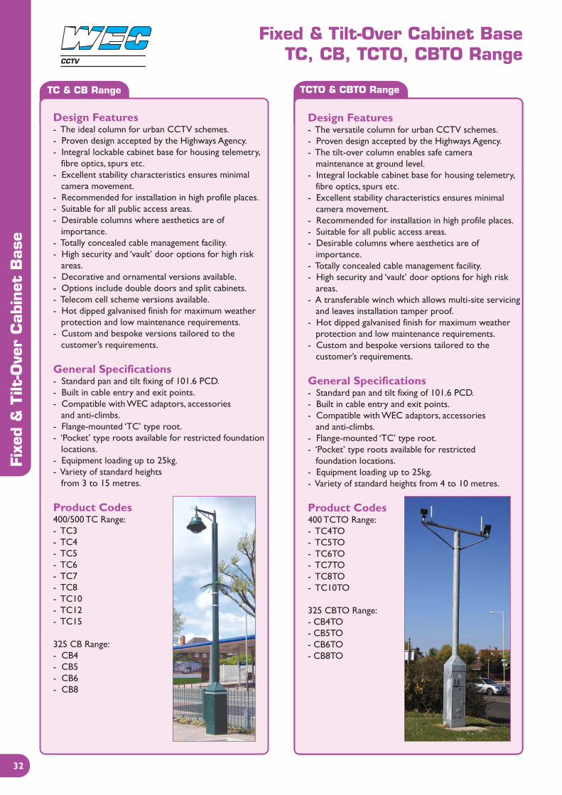
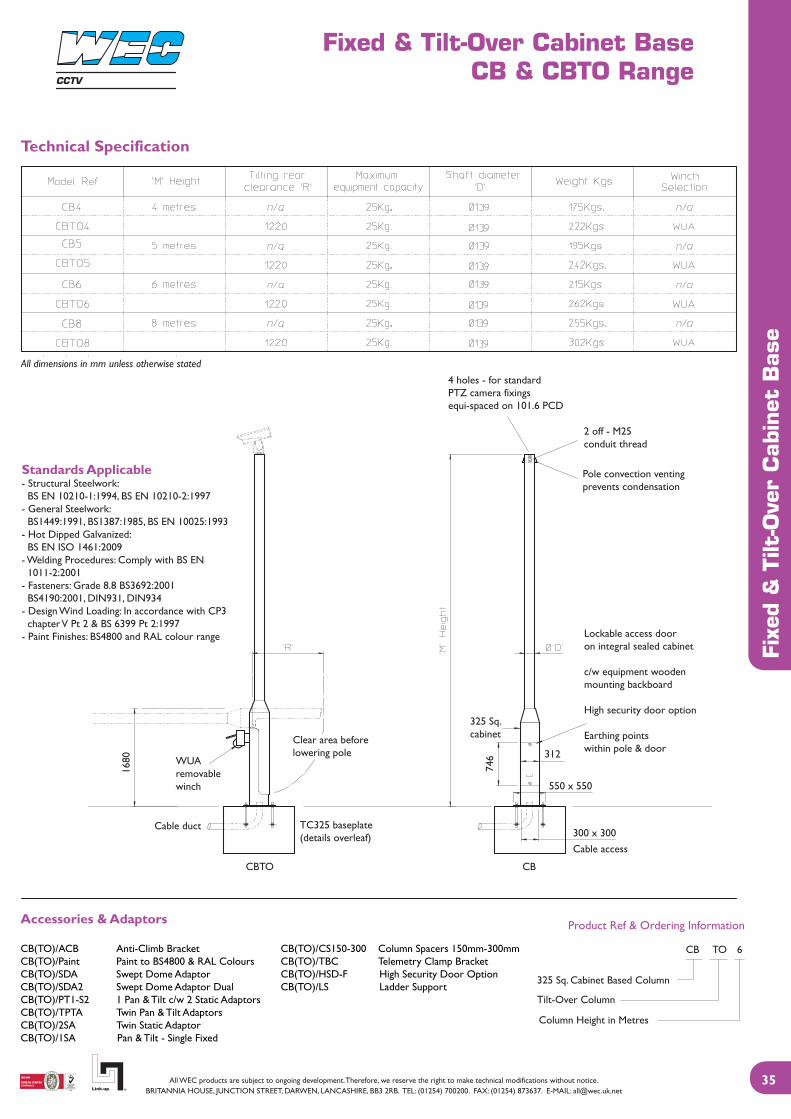
Fixed & Tilt-Over Cabinet BaseTC, CB, TCTO, CBTO Range
Fixe
d &
Tilt
-Ove
r C
abin
et B
ase
TC & CB Range TCTO & CBTO Range
The TC and CB range of CCTV columns remain thespecifiers number one choice for cabinet based columns,for use within city centre and urban schemes. The 400square cabinet remains the mainstay of this range ofcolumns, with cabinet options of 325 and 500 squarereadily available for terminating all communication andelectrical needs. The proven design, along with manyversatile features, keep it at the forefront of CCTVstreet furniture and it is still the industry standard.
The TC and CB range naturally evolved into the TCTOand CBTO range of tilt-over columns, for use withincity centre and urban schemes. The added bonus ofmaintenance at ground level make this a popular and safefirst choice where access for maintenance is of concern.The 400 square cabinet remains the mainstay of this range,with the 325 cabinet option readily available. The sturdy,proven design, along with many versatile features, keep it at the forefront of CCTV urban furniture with the addedbonus of tiltability.
CCTV
Fixed & Tilt-Over Cabinet BaseTC, CB, TCTO, CBTO Range
Fixe
d &
Tilt
-Ove
r C
abin
et B
ase
TC & CB Range TCTO & CBTO Range
Design Features- The ideal column for urban CCTV schemes.- Proven design accepted by the Highways Agency.- Integral lockable cabinet base for housing telemetry, fibre optics, spurs etc.- Excellent stability characteristics ensures minimal camera movement.- Recommended for installation in high profile places.- Suitable for all public access areas.- Desirable columns where aesthetics are of importance.- Totally concealed cable management facility.- High security and ‘vault’ door options for high risk areas.- Decorative and ornamental versions available.- Options include double doors and split cabinets.- Telecom cell scheme versions available.- Hot dipped galvanised finish for maximum weather protection and low maintenance requirements.- Custom and bespoke versions tailored to the customer’s requirements.
General Specifications- Standard pan and tilt fixing of 101.6 PCD.- Built in cable entry and exit points.- Compatible with WEC adaptors, accessories and anti-climbs.- Flange-mounted ‘TC’ type root.- ‘Pocket’ type roots available for restricted foundation locations.- Equipment loading up to 25kg.- Variety of standard heights from 3 to 15 metres.
Product Codes400/500 TC Range:- TC3- TC4- TC5- TC6- TC7- TC8- TC10- TC12- TC15
325 CB Range:- CB4- CB5- CB6- CB8
Design Features- The versatile column for urban CCTV schemes.- Proven design accepted by the Highways Agency.- The tilt-over column enables safe camera maintenance at ground level.- Integral lockable cabinet base for housing telemetry, fibre optics, spurs etc.- Excellent stability characteristics ensures minimal camera movement.- Recommended for installation in high profile places.- Suitable for all public access areas.- Desirable columns where aesthetics are of importance.- Totally concealed cable management facility.- High security and ‘vault’ door options for high risk areas.- A transferable winch which allows multi-site servicing and leaves installation tamper proof.- Hot dipped galvanised finish for maximum weather protection and low maintenance requirements.- Custom and bespoke versions tailored to the customer’s requirements.
General Specifications- Standard pan and tilt fixing of 101.6 PCD.- Built in cable entry and exit points.- Compatible with WEC adaptors, accessories and anti-climbs.- Flange-mounted ‘TC’ type root.- ‘Pocket’ type roots available for restricted foundation locations.- Equipment loading up to 25kg.- Variety of standard heights from 4 to 10 metres.
Product Codes400 TCTO Range: - TC4TO - TC5TO - TC6TO - TC7TO - TC8TO- TC10TO
325 CBTO Range:- CB4TO- CB5TO- CB6TO- CB8TO
CCTV

Fixed & Tilt-Over Cabinet BaseTC & TCTO Range
Fix
ed &
Tilt
-Ove
r C
abin
et B
ase
Product Ref & Ordering Information
Standards Applicable- Structural Steelwork: BS EN 10210-1:1994, BS EN 10210-2:1997- General Steelwork: BS1449:1991, BS1387:1985, BS EN 10025:1993- Hot Dipped Galvanized: BS EN ISO 1461:2009- Fasteners: Grade 8.8 BS3692:2001 BS4190:2001, DIN931, DIN934- Welding Procedures: Comply with BS EN 1011-2:2001- Design Wind Loading: In accordance with CP3 chapter V Pt 2 & BS 6399 Pt 2:1997- Paint Finishes: BS4800 and RAL colour range
Technical Specification
All dimensions in mm unless otherwise stated
4 holes - for standardPTZ camera fixingsequi-spaced on 101.6 PCD
2 off - M25conduit thread
Lockable access dooron integral sealed cabinet
c/w equipment woodenmounting backboard
Earthing pointswithin pole & door
WUAremovablewinch
Clear area beforelowering pole
Cable duct
Options & Accessories
Enlarged cabinet (500 Sq.)All pan/tilt, dome, fixed camera mount bracketryTransferable winch for tilt-over columnsDouble door access (partitioned cabinet)Camera wash equipment (static columns only)Ornate camera mounting brackets
Pole convection ventingprevents condensation
Decorative bandingfitted as an option
1730
746
312
‘TCTO’ ‘TC’
‘Pocket’ type rootavailable as an option
400 Sq.cabinet
Town Centre 400 Sq.Cabinet Based Column
Tilt-Over Column
Column Height in Metres
Heavy Duty Columnwhen minimum deflection is requiredi.e. high zoom lens camera
TC TO 6 HD
CCTV

Fixed & Tilt-Over Cabinet BaseTC & TCTO Range
Fixe
d &
Tilt
-Ove
r C
abin
et B
ase
Base and Windload Specification
Concrete Foundation Table X x Y x Z
A minimum soil bearing pressure of 75 KN/m2 is assumed
Installation Method
1. From the map, select location of installation2. Excavate as per recommended area and depth3. Assemble root base as shown in fig. 14. Insert root base into the hole ensuring that it is level and that the four studs protrude 60-70mm above the concrete foundation5. Fit the cable duct if routing via the interior of the column. A plastic pipe of approximately 100mm outside diameter is recommended for this. Ensure this protrudes through the template by 50mm minimum.6. Pour concrete ensuring that it is a mix of C35 to table 6 BS 8110 and then tamp down well7. Fit the setting template over the four protruding studs, double-checking that they are level and that clear access can be gained to the cable duct if it is being used8. Leave the concrete to cure for a minumum of 72 hours prior to attempting to erect the column9. When fitting the column, ensure that the concrete base is in complete contact with the underside of the column and grout accordingly 10. When the column has been fitted, protect the studs with a suitable protective coating. Denzo tape or similar is recommend for this
All studs mustbe level and square
fig. 1
Cable duct
Secure template to studsusing M24 nut top & bottom
Template
M24studs
Anchorplate
TC Root Assembly(4 bolt assembly shown)
300-
330
60-7
0
50
M24
‘TC’ 4 boltroot
‘TC’ 8 boltroot
450
550
550
crs.
575
crs.
645
Sq.
CCTV
Fixed & Tilt-Over Cabinet BaseCB & CBTO Range
Fixe
d &
Tilt
-Ove
r C
abin
et B
ase
Product Ref & Ordering Information
Standards Applicable- Structural Steelwork: BS EN 10210-1:1994, BS EN 10210-2:1997- General Steelwork: BS1449:1991, BS1387:1985, BS EN 10025:1993- Hot Dipped Galvanized: BS EN ISO 1461:2009- Welding Procedures: Comply with BS EN 1011-2:2001- Fasteners: Grade 8.8 BS3692:2001 BS4190:2001, DIN931, DIN934- Design Wind Loading: In accordance with CP3 chapter V Pt 2 & BS 6399 Pt 2:1997- Paint Finishes: BS4800 and RAL colour range
Technical Specification
All dimensions in mm unless otherwise stated
4 holes - for standardPTZ camera fixingsequi-spaced on 101.6 PCD
2 off - M25conduit thread
Lockable access dooron integral sealed cabinet
c/w equipment woodenmounting backboard
High security door option
Earthing pointswithin pole & door
WUAremovablewinch
Pole convection ventingprevents condensation
Clear area beforelowering pole
1680
Cable duct
325 Sq.cabinet
746 312
550 x 550
300 x 300Cable access
TC325 baseplate(details overleaf)
CBTO CB
Accessories & Adaptors
CB(TO)/ACB Anti-Climb Bracket CB(TO)/CS150-300 Column Spacers 150mm-300mmCB(TO)/Paint Paint to BS4800 & RAL Colours CB(TO)/TBC Telemetry Clamp BracketCB(TO)/SDA Swept Dome Adaptor CB(TO)/HSD-F High Security Door OptionCB(TO)/SDA2 Swept Dome Adaptor Dual CB(TO)/LS Ladder SupportCB(TO)/PT1-S2 1 Pan & Tilt c/w 2 Static AdaptorsCB(TO)/TPTA Twin Pan & Tilt AdaptorsCB(TO)/2SA Twin Static AdaptorCB(TO)/1SA Pan & Tilt - Single Fixed
325 Sq. Cabinet Based Column
Tilt-Over Column
Column Height in Metres
CB TO 6
CCTV

Fixed & Tilt-Over Cabinet BaseCB & CBTO Range
Fixe
d &
Tilt
-Ove
r C
abin
et B
ase
Base and Windload Specification
Foundation sizes are determined for three setsof wind speeds, which will cover most of theBritish Isles.
Area A = 44m/s (98mph)Area B = 48m/s (107mph)Area C = 52m/s (116mph)
Maximum gust speed is likely to be exceededon average once every 50 years at 10m abovethe ground in open level country.
Installation Method
1. From the map, select location of installation2. Excavate as per recommended area and depth3. Assemble root base as shown in fig. 14. Insert root base into the hole ensuring that it is level and that the four studs protrude 60-70mm above the concrete foundation5. Fit the cable duct if routing via the interior of the column. A plastic pipe of approximately 100mm outside diameter is recommended for this. Ensure this protrudes through the template by 50mm minimum.6. Pour concrete ensuring that it is a mix of C35 to table 6 BS 8110 and then tamp down well7. Fit the setting template over the four protruding studs, double-checking that they are level and that clear access can be gained to the cable duct if it is being used8. Leave the concrete to cure for a minumum of 72 hours prior to attempting to erect the column9. When fitting the column, ensure that the concrete base is in complete contact with the underside of the column and grout accordingly. Torque the nuts to 230-270 Nm (175-200 fl. lb.)10. When the column has been fitted, protect the studs with a suitable protective coating. Denzo tape or similar is recommend for this
Concrete Foundation Table X x Y x Z
A minimum soil bearing pressure of 75 KN/m2 is assumed
All four studs mustbe level and square
fig. 1
Cable duct
Secure template to studsusing M24 nut top & bottomTemplate
M24studs
Anchorplate
TC325 Root
60-7
0
300-
330
550 Sq.
450 crs.
M24
50
TC325 Root Assembly
CCTV
Fixed & Tilt-Over Cabinet BaseTC, CB, TCTO, CBTO Accessories
Fixe
d &
Tilt
-Ove
r C
abin
et B
ase
Conduit glandM25 threaded entry
Tube to wiperspray nozzle
Venting asstandard
Range of ornatearms available
Outline of customerCCTV camera
Decorative banding
Cabinet size options325 / 400 / 500
OptionCondensation driptray with outlet pipe
400 Sq. cabinet
CCTV equipment mountedonto marine ply backboard
Access door forwash bottle
5 litre wash bottle
Removable access door
3 options available- TCD- HSD- 4PL
Fan assisted cooling Double door accessfor partitioned cabinet(TC & CB only)
Stan
dard
ape
rtur
e
Tamperproofmicro switch
‘Pocket’ type rootavailable as an option
342
746
x 31
2
CCTV

Fixed & Tilt-Over Cabinet BaseTC, CB, TCTO, CBTO Accessories
Fixe
d &
Tilt
-Ove
r C
abin
et B
ase
Optional Extras
Door OptionsModerate risk area2 point locking
High risk area3 point locking
Very high risk area4 point locking
Compression latches,locks door & pulls tightwith one half turn
TCDStandard door
HSDHigh security door
4PL‘Vault’ type door
High security lockc/w protection shroud
Tamperproofescutcheon plate
4 off retractablelocking bolts
One key required
- Louvered door- Close fitting and flush door- Self grip rubber door seal- Secure compression locks- Earthing lugs
Two keys required
- Louvered door- Close fitting and flush door- Self grip rubber door seal- 2 secure compression locks and 1 high security lock- Earthing lugs- Protection shrouds for each lock
Three keys required
- Louvered door- Close fitting and flush door- 2 high security locks- Earthing lugs- Tamperproof escutcheons for each lock- Stainless steel locking mechanism
CCTV

Vandal Resistant & Anti-Ram ColumnsAD and AV Range
Van
dal R
esis
tant
& A
nti
-Ram
Col
umns
AD Range AV Range
The well established TC range of CCTV columns have evolved into extremely high security and vandal deterrent items.These columns are being used with success in out of town areas that demand a tamper proof and vandal resistant product.The 400 square cabinet remains the mainstay of this range, however the anti-vandal range has a double skinned cabinetfitted with an outer ‘hidden lock’ door and an inner ‘vault’ door. The column shaft features a loose cover sleeve that willturn should the shaft be attacked with mechanical cutting equipment. The vandal deterrent column is based on the standard400 square cabinet and features a ‘vault’ door, however the cabinet and shaft are constructed from a single skin of high grade,heavy duty steel. Both the AV and AD ranges can be supplied with the anti-ram raid base structure or anti-ram bollards toprotect the column. When using these types of column, it is advisable to protect the exposed camera from vandalism withcamera protection cages and anti-ladder brackets.
CCTV

Vandal Resistant & Anti-Ram ColumnsAD and AV Range
Van
dal R
esis
tant
& A
nti
-Ram
Col
umns
AD Range AV Range
Design Features- An ideal column for urban extreme risk CCTV schemes.- Integral lockable cabinet base for housing telemetry, fibre optics, spurs etc.- Heavy duty high grade steel, single skinned cabinet.- Excellent stability characteristics ensures minimal camera movement.- Recommended for installation in high risk and problem areas.- Camera mounting shaft made from heavy duty high grade steel.- Suitable for all public access areas.- Totally concealed cable management facility.- ‘Vault’ door as standard.- Options include double doors and split cabinets.- Telecom cell scheme versions available.- Anti-ram base structure and bollards available.- Hot dipped galvanised finish for maximum weather protection and low maintenance requirements.- Custom and bespoke versions tailored to the customer’s requirements.
General Specifications- Standard pan and tilt fixing of 101.6 PCD.- Built in cable entry and exit points.- Compatible with WEC adaptors, accessories and anti-climbs.- Flange-mounted ‘TC’ type root - 8 stud type.- ‘Pocket’ type roots available for restricted foundation locations.- Equipment loading up to 25kg.- Variety of standard heights from 3 to 15 metres.
Product CodesAnti-Vandal Range:- AD6- AD8- AD10- AD12- AD15
Options:- ARB1: anti-ram bollard- ALR: anti ladder rest
Design Features- An ideal column for urban extreme risk CCTV schemes.- Integral lockable cabinet base for housing telemetry, fibre optics, spurs etc.- Excellent stability characteristics ensures minimal camera movement.- Recommended for installation in high risk and problem areas.- Double doors and double skinned cabinet for ultimate protection.- Double skinned column shaft with spinner tube.- Suitable for all public access areas.- Totally concealed cable management facility.- Hidden lock and ‘vault’ door as standard.- Options include double doors and split cabinets.- Telecom cell scheme versions available.- Anti-ram base structure and bollards available.- Hot dipped galvanised finish for maximum weather protection and low maintenance requirements.- Custom and bespoke versions tailored to the customer’s requirements.
General Specifications- Standard pan and tilt fixing of 101.6 PCD.- Built in cable entry and exit points.- Compatible with WEC adaptors, accessories and anti-climbs.- Flange-mounted ‘TC’ type root - 8 stud type.- ‘Pocket’ type roots available for restricted foundation locations.- Equipment loading up to 25kg.- Variety of standard heights from 3 to 15 metres.
Product CodesAnti-Randal Range:- AV6- AV8- AV10- AV12- AV15
Options:- ARB1: anti-ram bollard- ALR: anti ladder rest
CCTV

Vandal Resistant & Anti-Ram ColumnsAD and AV Range
Van
dal R
esis
tant
& A
nti
-Ram
Col
umns
Technical Specification
Single skin heavy dutyshaft
‘M’ H
eigh
t
Drop bar
Single skin400 Sq. heavy duty cabinet
Cable duct Cable duct
Cable duct
Heavy duty 400 Sq. cabinet10 thk door & case8 bolt fixing
Heavy duty 500 Sq. double skin cabinet10 thk outer door & caseInner door 4 point locking8 bolt fixing
Ram raid basefor use with AV or AVR8 bolt fixing
AD AVRRB
355 355
1240 1240
789
789
Drop bar
Double skin500 Sq. cabinet
Climb guardsavailable
Removable top givesaccess into cage
Heavy duty cylindrical cameracages are available to suit the column
Details on door locking system are available
CCTV

Van
dal R
esis
tant
& A
nti
-Ram
Col
umns
Vandal Resistant & Anti-Ram ColumnsAD and AV Range
Base and Windload Specification
Foundation sizes are determined for three setsof wind speeds, which will cover most of theBritish Isles.
Area A = 44m/s (98mph)Area B = 48m/s (107mph)Area C = 52m/s (116mph)
Maximum gust speed is likely to be exceededon average once every 50 years at 10m abovethe ground in open level country.
Installation Method
1. From the map, select location of installation2. Excavate as per recommended area and depth3. Assemble root base as shown in fig. 14. Insert root base into the hole ensuring that it is level and that the four studs protrude 60-70mm above the concrete foundation5. Fit the cable duct if routing via the interior of the column. A plastic pipe of approximately 100mm outside diameter is recommended for this. Ensure this protrudes through the template by 50mm minimum.6. Pour concrete ensuring that it is a mix of C35 to table 6 BS 8110 and then tamp down well7. Fit the setting template over the four protruding studs, double-checking that they are level and that clear access can be gained to the cable duct if it is being used8. Leave the concrete to cure for a minumum of 72 hours prior to attempting to erect the column9. When fitting the column, ensure that the concrete base is in complete contact with the underside of the column and grout accordingly. Torque the nuts to 230-270 Nm (175-200 fl. lb.)10. When the column has been fitted, protect the studs with a suitable protective coating. Denzo tape or similar is recommend for this
Concrete Foundation Table X x Y x Z
A minimum soil bearing pressure of 75 KN/m2 is assumed
CCTV

Trolley PolesETP and CBTP Range
Trol
ley
Pol
es
ETP Range CBTP Range
The ETP and CBTP ranges are the very peak in CCTV mounting poles. With various options of built in ortransferable electric or manual winches, the ranges enable cost-effective and more importantly safe cameramaintenance at ground level. These columns has been designed within the Highways Agency specification andwith their excellent reliability record, have become the number one choice in urban traffic monitoring schemes.The ETP range is a continuous parallel column, whereas the CBTP range has the added bonus of a spaciouscabinet base at the bottom for more complex electrical and communications use. Both ranges can be seen incity centres and on trunk roads throughout the United Kingdom.
CCTV
Trolley PolesETP and CBTP Range
ETP Range CBTP Range
Trol
ley
Pol
es
Design Features- An ideal column for urban and traffic CCTV schemes.- Designed in accordance with Highways Agency specification.- Eliminates the use of mechanical lifts for servicing purposes.- Camera maintenance carried out at ground level. The camera head rotates through 180 degrees for servicing purposes.- Various built in and transferable winch options.- In-built carriage failsafe braking mechanism.- Excellent stability characteristics ensures minimal camera movement.- Recommended for installation in high profile places.- Suitable for all public access areas.- Camera carriage unit has a self clamping mechanism to minimise deflection when in its working position.- Totally concealed cable management facility.- High security door option for high risk areas.- Hot dipped galvanised finish for maximum weather protection and low maintenance requirements.- Custom and bespoke versions tailored to the customer’s requirements.
General Specifications- Standard pan and tilt fixing of 101.6 PCD.- Special dome mounting brackets available.- Built in cable entry and exit points.- Compatible with WEC adaptors, accessories and anti-climbs.- Flange-mounted ‘TC’ type root.- ‘Pocket’ type roots available for restricted foundation locations.- Equipment loading up to 25kg.- Variety of standard heights from 3 to 15 metres.
Product CodesEconomy Trolley Pole Range:- ETP6- ETP7- ETP8- ETP9- ETP10- ETP12- ETP13- ETP14- ETP15
Design Features- An ideal column for urban and traffic CCTV schemes.- Designed in accordance with Highways Agency specification.- Eliminates the use of mechanical lifts for servicing purposes.- Integral lockable cabinet base for housing telemetry, fibre optics, spurs etc.- Camera maintenance carried out at ground level. The camera head rotates through 180 degrees for servicing purposes.- Various built in and transferable winch options.- In-built carriage failsafe braking mechanism.- Excellent stability characteristics ensures minimal camera movement.- Recommended for installation in high profile places.- Suitable for all public access areas.- Options include double door and split cabinets.- Telecom cell scheme versions available.- Camera carriage unit has a self clamping mechanism to minimise deflection when in its working position.- Totally concealed cable management facility.- High security and ‘vault’ door options for high risk areas.- Hot dipped galvanised finish for maximum weather protection and low maintenance requirements.- Custom and bespoke versions tailored to the customer’s requirements.
General Specifications- Standard pan and tilt fixing of 101.6 PCD.- Special dome mounting brackets available.- Built in cable entry and exit points.- Compatible with WEC adaptors, accessories and anti-climbs.- Flange-mounted ‘TC’ type root.- ‘Pocket’ type roots available for restricted foundation locations.- Equipment loading up to 25kg.- Variety of standard heights from 3 to 15 metres.
Product CodesCabinet Based TrolleyPole Range:- CBTP6- CBTP7- CBTP8- CBTP9- CBTP10- CBTP12- CBTP13- CBTP14- CBTP15
CCTV
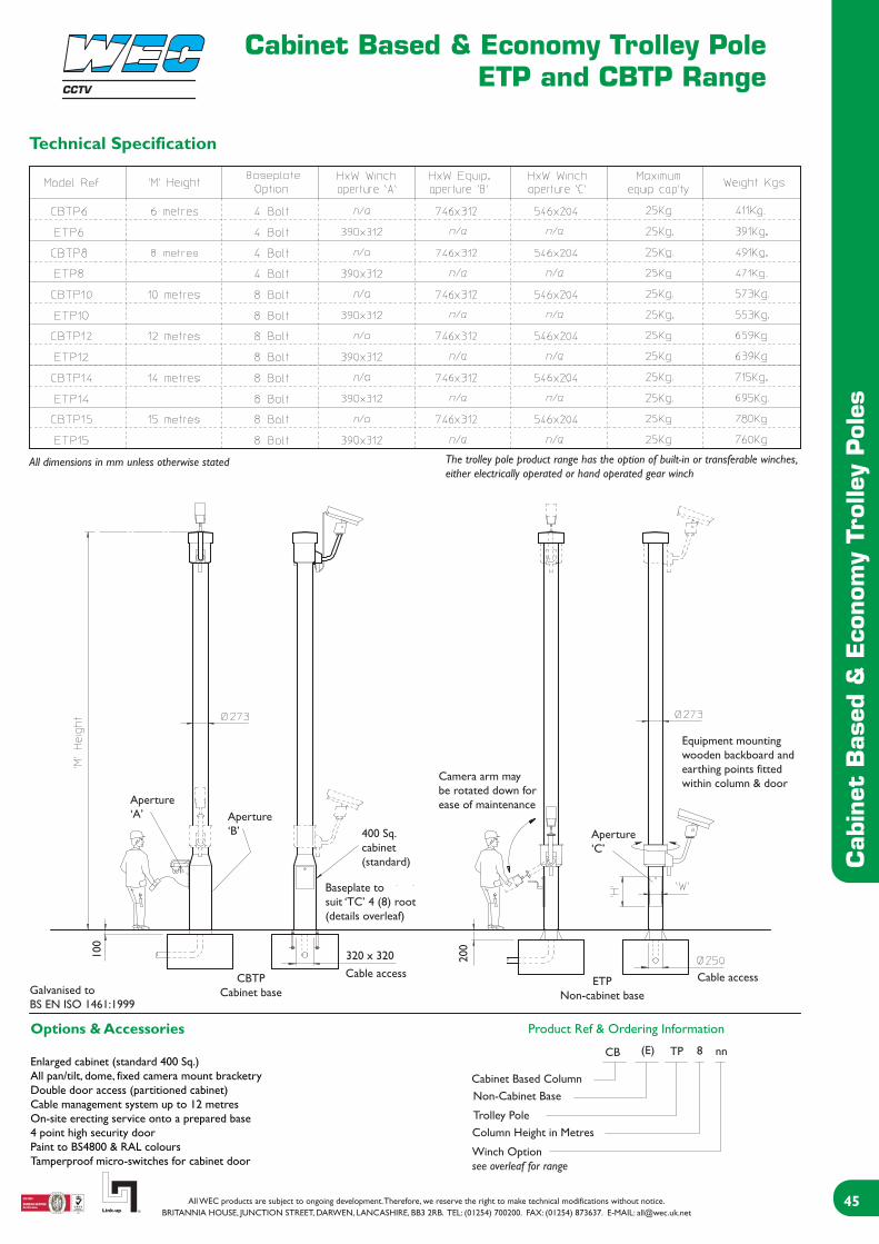
Cabinet Based & Economy Trolley PoleETP and CBTP Range
Cab
inet
Bas
ed &
Eco
nom
y Tr
olle
y Pol
es
Product Ref & Ordering Information
Technical Specification
All dimensions in mm unless otherwise stated The trolley pole product range has the option of built-in or transferable winches, either electrically operated or hand operated gear winch
Aperture‘A’ Aperture
‘B’ Aperture‘C’
400 Sq.cabinet(standard)
Camera arm maybe rotated down forease of maintenance
Equipment mountingwooden backboard andearthing points fittedwithin column & door
320 x 320Cable access
100
Galvanised toBS EN ISO 1461:1999
CBTPCabinet base
ETPNon-cabinet base
200
Cable access
Baseplate tosuit ‘TC’ 4 (8) root(details overleaf)
Options & Accessories
Enlarged cabinet (standard 400 Sq.)All pan/tilt, dome, fixed camera mount bracketryDouble door access (partitioned cabinet)Cable management system up to 12 metresOn-site erecting service onto a prepared base4 point high security doorPaint to BS4800 & RAL coloursTamperproof micro-switches for cabinet door
Cabinet Based ColumnNon-Cabinet Base
Trolley PoleColumn Height in Metres
Winch Optionsee overleaf for range
CB (E) TP 8 nn
CCTV
Cabinet Based & Economy Trolley PoleETP and CBTP Accessories
Cab
inet
Bas
ed &
Eco
nom
y Tr
olle
y Pol
es
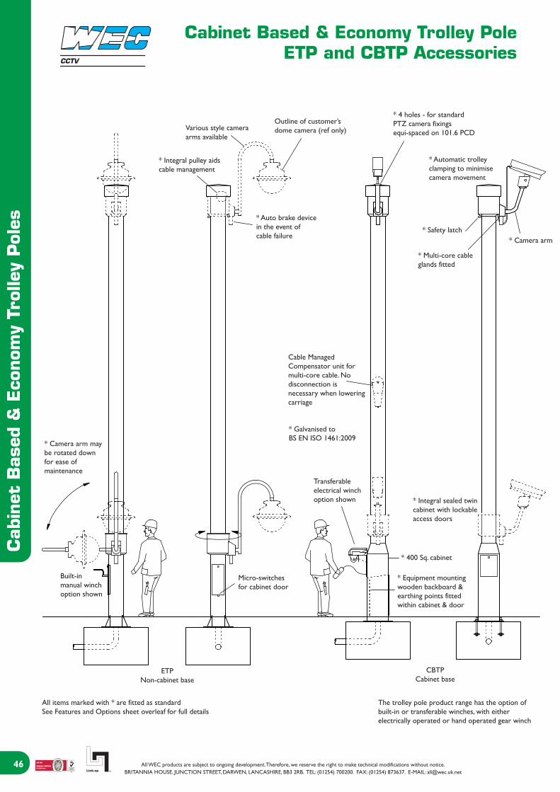
Various style cameraarms available
* Integral pulley aidscable management
Outline of customer’sdome camera (ref only)
* 4 holes - for standardPTZ camera fixingsequi-spaced on 101.6 PCD
* Automatic trolleyclamping to minimisecamera movement
* Auto brake devicein the event of cable failure
* Safety latch
* Multi-core cableglands fitted
* Camera arm
Cable ManagedCompensator unit formulti-core cable. Nodisconnection isnecessary when loweringcarriage
* Galvanised toBS EN ISO 1461:2009
* Camera arm maybe rotated downfor ease ofmaintenance
Transferableelectrical winchoption shown * Integral sealed twin
cabinet with lockableaccess doors
Built-inmanual winchoption shown
Micro-switchesfor cabinet door
* 400 Sq. cabinet
* Equipment mountingwooden backboard &earthing points fittedwithin cabinet & door
ETPNon-cabinet base
CBTPCabinet base
All items marked with * are fitted as standardSee Features and Options sheet overleaf for full details
The trolley pole product range has the option ofbuilt-in or transferable winches, with eitherelectrically operated or hand operated gear winch
CCTV
Cabinet Based & Economy Trolley PoleETP and CBTP Range
Cab
inet
Bas
ed &
Eco
nom
y Tr
olle
y Pol
es
Options for CBTP & ETP Range
HT Transferable manual winchHB Manual winch built into columnEH Spare winch handleCM Cable management500 Enlarged cabinet size of 500mm Sq.2C Separate compartments in cabinetEDK Spare cabinet door keysPKT Alternative ‘pocket’ type root fixingET Transferable electric winch (Pat.No. 0019862.2)EBA Electric winch built into columnPS Spare pendant for EBR110V 110V transformer for EBA or EBR
General Options for CBTP & ETP Range
- Cable management system - fitting compensator & customer free issue cable- High security door- Vault type door (4 point locking)- 500 cabinet base (CBTP only)- On-site erecting service onto a prepared base- Painting finishes in BS4800 and RAL colours- Swept dome adaptors for dome type cameras- Tamperproof micro-switched for cabinet door
Full Cable Management
WEC offer full cable management within the trolley poleup to 12 metres. This feature eliminates the need todisconnect the camera multi-core cable, when the camerais lowered to the maintenance position.
Delivery and Erection
WEC offers a full delivery and column erecting service ontoa prepared concerete base, anywhere within the UK.
Delivery and Placement
WEC offers a full projeect management level of delivery andinstallation. Despite not carrying out the civil work, we offeradvice on optimum site location, concrete base sizes (standard and specials), along with placement of pole ontoconcrete plinth through to commissioning on site.
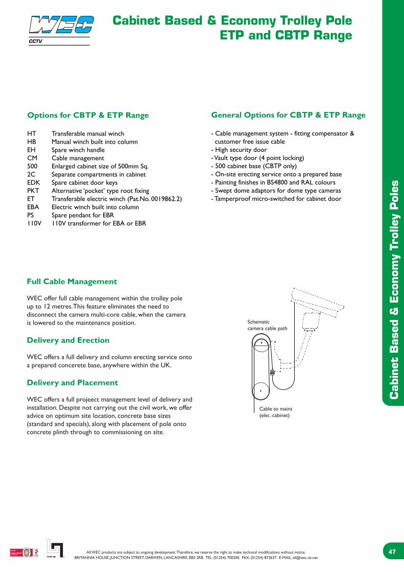
Schematiccamera cable path
Cable to mains(elec. cabinet)
CCTV

Cabinet Based & Economy Trolley PoleETP and CBTP Range
Cab
inet
Bas
ed &
Eco
nom
y Tr
olle
y Pol
es
Base and Windload Specification
Concrete Foundation Table X x Y x Z
A minimum soil bearing pressure of 75 KN/m2 is assumed
Installation Method
1. From the map, select location of installation2. Excavate as per recommended area and depth3. Assemble root base as shown in fig. 14. Insert root base into the hole ensuring that it is level and that the four studs protrude 60-70mm above the concrete foundation5. Fit the cable duct if routing via the interior of the column. A plastic pipe of approximately 100mm outside diameter is recommended for this. Ensure this protrudes through the template by 50mm minimum.6. Pour concrete ensuring that it is a mix of C35 to table 6 BS 8110 and then tamp down well7. Fit the setting template over the four protruding studs, double-checking that they are level and that clear access can be gained to the cable duct if it is being used8. Leave the concrete to cure for a minumum of 72 hours prior to attempting to erect the column9. When fitting the column, ensure that the concrete base is in complete contact with the underside of the column and grout accordingly. Torque the nuts to 230-270 Nm (175-200 fl. lb.) 10. When the column has been fitted, protect the studs with a suitable protective coating. Denzo tape or similar is recommend for this
All studs mustbe level and square
300-
330
60-7
0
50
M24
‘TC’ 4 boltroot baseplate
for height range6m to 8m
‘TC’ 8 boltroot baseplate
for height above10m+
450
550
550
crs.
575
crs.
645
Sq.
Anchorplate
Template
OptionHighways Agency Flange8 bolt root
CCTV

Wall and Corner PolesWPT and WPTA Range
Wal
l an
d C
orner
Pol
es
Wall Poles
CCTV

Wall and Corner PolesWPT and WPTA Range
Wal
l an
d C
orner
Pol
es
Wall Poles
The WP and CP ranges have, for many years, provided theindustry standard solution for many camera mountingsituations. Available in standard heights up to 6 metreswith stand off brackets from flush to 1000mm, both thewall and corner poles provide an excellent platform forobtaining an elevated viewpoint from existing structures.
Design Features- A cost-effective solution for achieving desired camera height.- Off the shelf heights up to 6 metres.- Standard models give up to 4 metres clearance above roofs, parapets and walls.- Rigid structure ensures excellent stability characteristics.- Various stand off brackets to clear facias, gutters and copings.- Modular construction for ease of transportation and erection.- Wall and corner mounted versions available.- Hot dipped galvanised finish for maximum weather protection and low maintenance requirements.- Custom and bespoke versions tailored to the customer’s requirements.
General Specifications- Standard pan and tilt fixing of 101.6 PCD.- Stand off brackets 000mm/150mm/300mm/500mm/1000mm.- Compatible with WEC adaptors, accessories and anti-climbs.- Equipment loading up to 25kg.- Variety of standard heights up to 6 metres.
Product Codes- 2.5WP000, 2.5WP150*, 2.5WP300*, 2.5WP500* 2.5WP1000- 3WP000, 3WP150, 3WP300, 3WP500, 3WP1000- 4WP000, 4WP150*, 4WP300*, 4WP500*, 4WP1000- 5WP000, 5WP150*, 5WP300*, 5WP500*, 5WP1000- 6WP000, 6WP150*, 6WP300*, 6WP500*, 6WP1000- 2.5CP000, 2.5CP150*, 2.5CP300*, 2.5CP500* 2.5CP1000- 3CP000, 3CP150, 3CP300, 3CP500, 3CP1000- 4CP000, 4CP150*, 4CP300*, 4CP500*, 4CP1000- 5CP000, 5CP150*, 5CP300*, 5CP500*, 5CP1000- 6CP000, 6CP150*, 6CP300*, 6CP500*, 6CP1000
*Ex-stock items
Technical Specification
CCTV
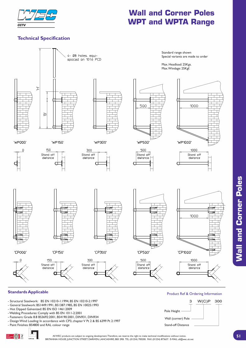
Wall and Corner PolesWPT and WPTA Range
Wal
l an
d C
orner
Pol
es
Technical Specification
Product Ref & Ordering InformationStandards Applicable
- Structural Steelwork: BS EN 10210-1:1994, BS EN 10210-2:1997- General Steelwork: BS1449:1991, BS1387:1985, BS EN 10025:1993- Hot Dipped Galvanized: BS EN ISO 1461:2009- Welding Procedures: Comply with BS EN 1011-2:2001- Fasteners: Grade 8.8 BS3692:2001, BS4190:2001, DIN931, DIN934- Design Wind Loading: In accordance with CP3, chapter V Pt 2 & BS 6399 Pt 2:1997- Paint Finishes: BS4800 and RAL colour range
Standard range shownSpecial variants are made to order
Max. Headload: 25Kgs.Max. Windage: 25Kgf.
Pole Height
Wall (corner) Pole
Stand-off Distance
CCTV

Wall and Corner PolesWPT and WPTA Range
Technical Specification
Wal
l an
d C
orner
Pol
es
Product Ref & Ordering Information
Std PTZ fixing4-M6 holes on101.6 PCD
M25 conduitcable exit
Side elevationHeight Range- 2.5m- 3.0m- 4.0m- 5.0m- 6.0m
5000
1700
500
Stand-off
Stand-off Range- 150- 500
Removable orfixed hand winch
Front elevation
Standard range shownSpecial variants are made to order
Max. Headload: 25Kgs.Max. Windage: 25Kgf.
Wall Mounted Tilt-Down PoleModel Ref Shown: 5WPTD500
Wall Mounted Tilt-Away PoleModel Ref Shown: 5WPTD500
Height Range- 2.5m- 3.0m- 4.0m- 5.0m- 6.0m
Parapet Mounted Tilt-Away PoleModel Ref Shown: 4PMTA150
Height Range- 2.5m- 3.0m- 4.0m- 5.0m- 6.0m
5000
Wall mount Corner MountRemovable orfixed handwinch
4000
Removable orfixed handwinch
500
Stand-off
Stand-off Range- 330- 400- 500
150
Stand-off
Stand-off Range- 360- 500
Standards Applicable
- Structural Steelwork: BS EN 10210-1:1994, BS EN 10210-2:1997- General Steelwork: BS1449:1991, BS1387:1985, BS EN 10025:1993- Hot Dipped Galvanized: BS EN ISO 1461:2009- Welding Procedures: Comply with BS EN 1011-2:2001- Fasteners: Grade 8.8 BS3692:2001, BS4190:2001, DIN931, DIN934- Design Wind Loading: In accordance with CP3, chapter V Pt 2 & BS 6399 Pt 2:1997- Paint Finishes: BS4800 and RAL colour range
Pole Height
Wall (corner) Pole
Stand-off Distance
Tilt Away (Down)
CCTV

Highway Structures
Hig
hw
ay S
truc
ture
s
Gantry Mounted Poles Gantry Brackets
Our highways division specialises in the design, manufacture and installation of various motorway poles and brackets.We can offer full site surveys and commissioning for customers requiring a more bespoke product.
Motorway Poles
CCTV
Gantry Brackets
Gantry Brackets
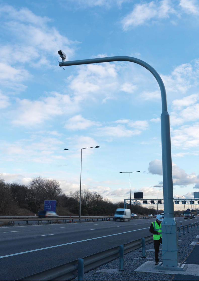
WEC offers a wide range of road side cabinets, from standard off the shelf products to those tailor made to specificcustomer requirements.
The standard road side cabinets are available in a variety of sizes and manufactured from materials such as stainlesssteel, aluminium or with a galvanised finish. These standard cabinets include an extensive range of hardware and caneven be fully wired and terminated to suit the customer’s requirements. Furthermore, WEC’s road side cabinets areavailable in a comprehensive selection of colours and on a short lead time basis.
WEC is able to manufacture and supply road side cabinets to customer drawings and offer a design service to producecabinets tailored to customer requirements.
Encl
osur
es
EnclosuresRSC Range
Enclosures
CCTV

EnclosuresRSC Range
Encl
osur
es
Technical Specification
Product Ref & Ordering Information
All dimensions in mm unless otherwise stated
Ventilationslots
Compression locksfitted as standard
OptionBuried Root
Marine plybackboard
Ventilationlouvre
Finish ground level
22 (typl)
Flush fit door
Rubbercompressionseal fittedon door
Cable duct
100
All our road side cabinets are constructed from stainless steel (3CR12) and powder coated with a black finish as standard
Options & Accessories
RC/HSD High security locking systemRC/4PL Extra high security 4 point lock systemRC/A4 Document holder (A4)RC/Col Paint to BS4800 & RAL coloursRC/F Fixed fan & dust extractionRC/19F Fixed 19” rackingRC/19H Swing out 19” rackingRC/IP65 IP65 rated cabinet
Door may be specified ashinged (either hand) or lift out
Double door access ontwin compartments
Treated equipment mountingbackboard or shelving
Roadside Cabinet
1000H x 1000W x 400D
High Security Dooroption reference
CCTV

AccessoriesAccessory RangeCCTV
Accessories
Acc
esso
ries

Anti-Climb BracketsACB Range
Anti
-Clim
b B
rack
ets
CCTV
BS EN ISO 1461:2009
Comply with BS EN 1011-2:2001

External Brackets - Fixed CameraHB Range
Ext
ernal
Bra
cket
s - Fi
xed
Cam
era
BS EN ISO 1461:2009
Comply with BS EN 1011-2:2001
CCTV

External Brackets - Pan & Tilt CameraHD PTZ Range
Ext
ernal
Bra
cket
s - Pan
& T
ilt C
amer
a
CCTV
BS EN ISO 1461:2009
Comply with BS EN 1011-2:2001

External Brackets - Pan & Tilt CameraHD PTZ Range
Ext
ernal
Bra
cket
s - Pan
& T
ilt C
amer
a
CCTV
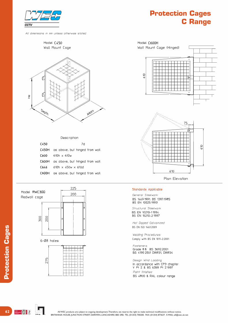
Protection CagesC Range
Pro
tect
ion C
ages
CCTV
BS EN ISO 1461:2009
Comply with BS EN 1011-2:2001

Protection CagesC Range
Pro
tect
ion C
ages
CCTV
BS EN ISO 1461:2009
Comply with BS EN 1011-2:2001

Swept Dome AdaptorsSDA Range
Sw
ept
Dom
e A
dapt
ors
CCTV
BS EN ISO 1461:2009
Comply with BS EN 1011-2:2001
Various Dome Fittings available
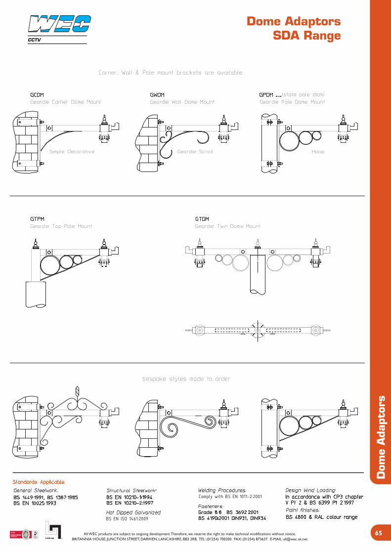
Dome AdaptorsSDA Range
Dom
e A
dapt
ors
BS EN ISO 1461:2009
Comply with BS EN 1011-2:2001
CCTV

Dome AdaptorsSDA Range
Dom
e A
dapt
ors
BS EN ISO 1461:2009
Comply with BS EN 1011-2:2001
CCTV
Various Dome Fittings available
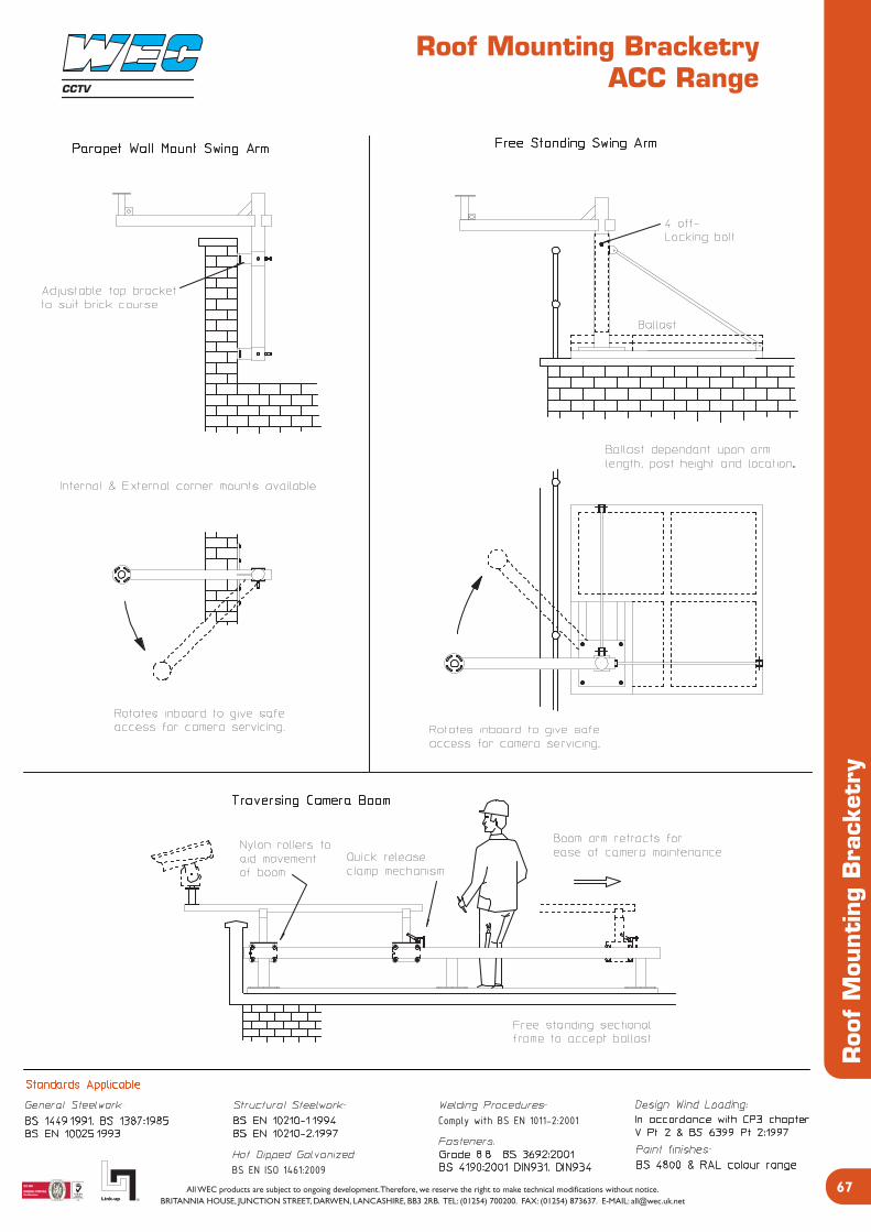
Roof Mounting BracketryACC Range
Roo
f M
ounti
ng
Bra
cket
ry
CCTV
BS EN ISO 1461:2009
Comply with BS EN 1011-2:2001

AccessoriesACC Range
Acc
esso
ries
BS EN ISO 1461:2009
Comply with BS EN 1011-2:2001
CCTV
Also available in a “3-in-line” version

AccessoriesACC RangeCCTV
Acc
esso
ries
BS EN ISO 1461:2009
Comply with BS EN 1011-2:2001
Also available in a “4-in-line” version

AccessoriesACC Range
BS EN ISO 1461:2009
Comply with BS EN 1011-2:2001
Acc
esso
ries
CCTV
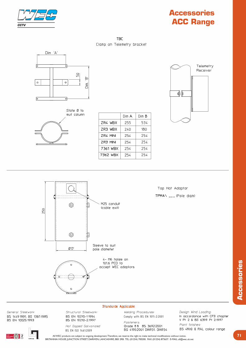
AccessoriesACC Range
Acc
esso
ries
BS EN ISO 1461:2009
Comply with BS EN 1011-2:2001
CCTV
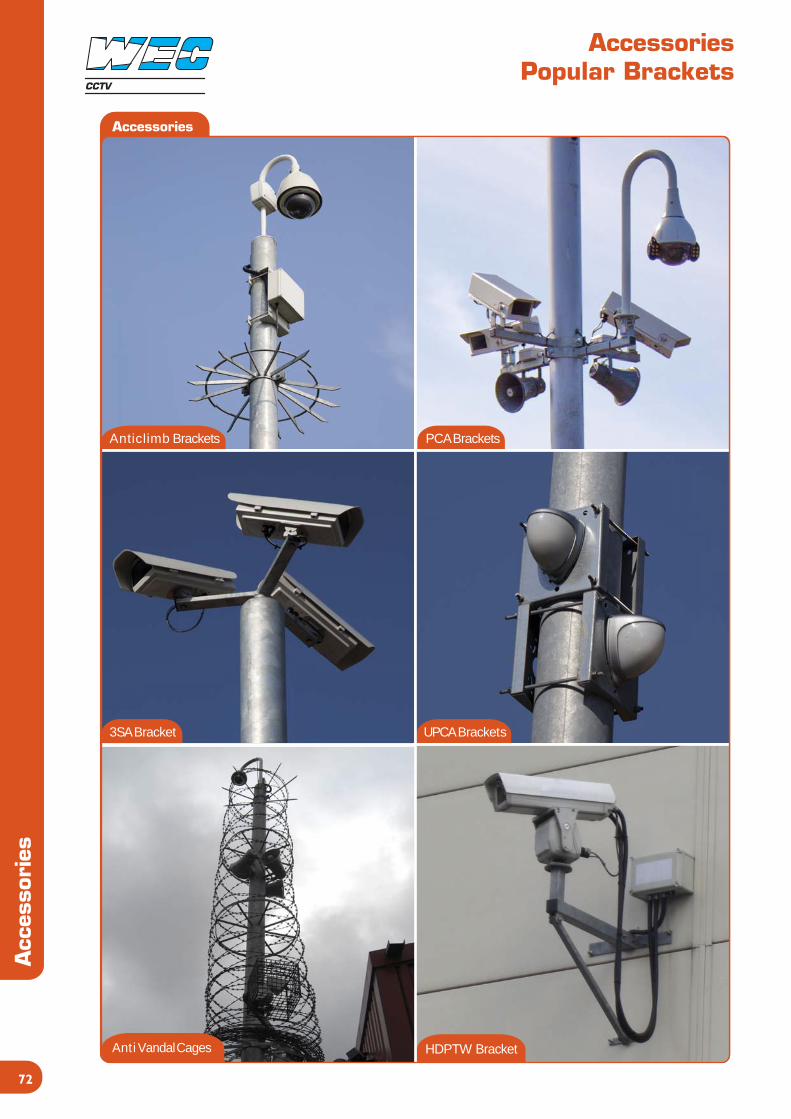
A n t i c l i m b B r a c k e t s P C A B r a c k e t s
3 S A B r a c k e t U P C A B r a c k e t s
H D P T W B r a c k e tA n t i V a n d a l C a g e s
AccessoriesPopular Brackets
Acc
esso
ries
CCTV
Accessories

TC Root FM Root
ST Root ST / AF
WD Root WD / AF
FMPKTTCPKTstate type
FMTDBFMSDBstate type
Root InformationRoots
Roo
t In
form
atio
n
Roots
CCTV
73

MiscellaneousCard Reader / Access Posts
Mis
cella
neo
us
CCTV
Gallery
Custom Stainless Steel Reader Post Single Height Access Post
Custom Information PostCustom Stainless Steel Intercom Post
74

Product GalleryRecent Projects
Gal
lery
Gallery
CCTV
TC6TO with double arms bracket ST6 Lattice Tower
TC8TOCB6
75
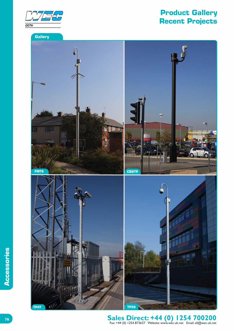
Product GalleryRecent Projects
Acc
esso
ries
CCTV
Gallery
FMT8 CB8TP
TP5STP4T
76

Product GalleryRecent Projects
Gal
lery
TC8
CCTV
77
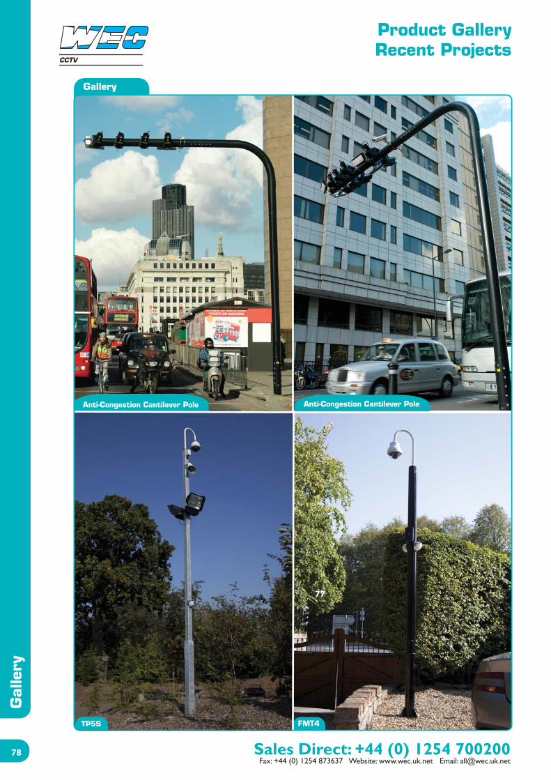
Product GalleryRecent Projects
Gal
lery
CCTV
Gallery
Anti-Congestion Cantilever Pole Anti-Congestion Cantilever Pole
FMT4TP5S
78
77
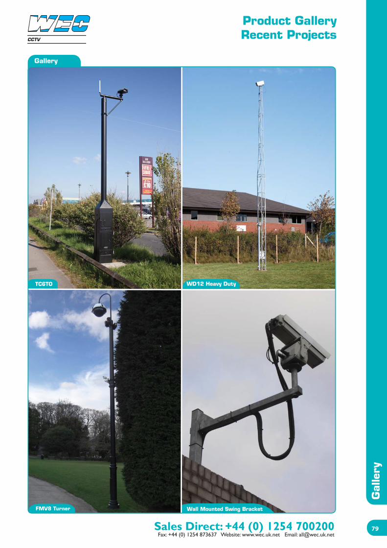
Product GalleryRecent Projects
Gal
lery
Gallery
CCTV
TC6TO WD12 Heavy Duty
Wall Mounted Swing BracketFMV8 Turner
79

Product GalleryRecent Projects
Gal
lery
CCTV
Gallery
7780
Terms & Conditions
Term
s &
Con
diti
ons
1. The Contents of this Contract.a. In this contract ‘the Company’ means WEC Group Limited. The ‘Goods’ means the goods or services sold or supplied by the Company to the Customer under this Contract. ‘This Contract’ means a Contract between the Customer and the Company incorporating these conditions.b. This Contract governs the sale of Goods by the Company to the exclusion of all other representations, statements, understanding, negotiations, proposals or agreements.c. Where the Customer submits its own order form, these terms shall prevail if they conflict with the terms in that form, even if that form includes a condition silmilar to this one.d. No employee of the Company or its agents has authority to make any warranty, statement or promise concerning the goods, except in writing signed by a duly authorised employee of the Company.e. The Customer’s order shall be subject to acceptance by the Company.f. Orders are accepted and estimates of delivery given conditionally on the Company being able to secure the necessary labour or material and without responsibility for delays or non-fulfilment arising through risk and uncertainties of manufacture, strikes, accidents, force majeure or otherwise however caused.g. All drawings, descriptive and forwarding specifications, particular of weights and dimensions are approximate only and not binding and illustrations contained in catalogues, sales literature and other advertising material are for the purpose of general description only and none of these shall form part of this Contract.
2. Pricesa. We reserve the right to invoice at the price ruling at date of despatch. All prices, unless otherwise stated, are exclusive of value added tax or any other duty which is or may be levied or charged in the UK or in the country of destination. Any such taxes, duties or charges shall be paid by the Customer.b. Unless otherwise specified, packing cases and pallets will be charged extra, but will be credited in full on return carriage paid and in one month by the Customer. Export packing cases are not returnable.c. The prices quoted are subject to any increase in the cost of labour or material between the date of quotation and despatch of Goods from our works and do not include installation costs.
3. Property of Goodsa. Property of Goods delivered by the Company shall not pass to the Customer until payment is made in full. In the case of default in payment, the Company shall be granted access rights in order to repossess the Goods. At all times before payment in full, the Goods shall stand in the Customer’s books in the name of the Company and the Customer shall take appropriate steps to notify third parties of the Company’s interest in the Goods andb. In the event of threatened seizure of the Goods or appointment of a receiver or liquidator, or any other event entitling the Company to terminate this Contract under paragraph 8, the Customer shall immediately notify the Company. The Company shall be entitled to enter the Company’s premises and repossess the goods.c. If the Customer delivers the Goods to a third party, before payment has been made in full to the Company, the Customer shall hold all sums received for such Goods as trustee for the Company and shall remit them to the Company on receipt.d. Risk in the Goods shall pass on delivery.
4. Deliverya. Delivery shall be ‘ex-works’ unless otherwise agreed. If the Contract includes delivery by the Company or its nominated contractor, the Customer is responsible for giving the Company clear and accurate information as to the place of delivery.b. Time shall not be of the essence in respect of delivery. If the Goods are to be delivered by a date specified by the Customer or the Company, such date is to be treated as an estimate only. The Company does not guarantee that the Goods will be delivered by such date or accept liability or any consequential losses for failure to meet the date.
5. Settlement Termsa. Home Sales: Where credit facilities exist, accounts are due for payment within 30 days of the end of the month of delivery. Where special discount terms are quoted, the terms must be strictly adhered to otherwise the account will be charged nett. The Customer shall, unless agreed in writing, pay all sums to the Company under the Contract prior to delivery in cash or cleared cheque in pounds sterling. If for any reason the Company does not receive unconditional payment in full, whether under any terms of credit facilities or otherwise, within 30 days of month end delivery, then the Company may charge daily interest on such payments at a rate equal to 4% per annum above the Based lending rate of the National Westminister Bank plc., with such interest to run from day to day to accrue before as well as after any judgement.b. Overseas and Export Sales: Special terms will be quoted for overseas deliveries.c. If we incur third party costs such as tracing, debt collection agency or seek to take legal proceedings to enforce our rights as a result of breach of this Contract, including but not limited to recovery of all sums due, the Customer will be liable to reimburse the Company such costs incurred on an indemnity basis.
6. Deliveriesa. The Company does not accept responsibility for any damage, shortage or loss in transit unless:i) Non-receipt of Goods is advised to the Company within 10 days from the date of the Company’s advice/delivery note andii) Any breakage, damage or shortage is advised to the Company and carriers within 3 days of receipt of goods, provided that the carrier’s note is marked ‘unexamined’.b. All sizes are approximate. Variations during the course of manufacture cannot be avoided and liability is not accepted for them. Where exact and detailed dimensions on standard products are required, then please contact our Technical Department for details.c. When Goods are offered and supplied to a Customer’s design and specification, no guarantee is given or implied of their suitability for the purpose of which they are intended.d. In cases where fixings and holding down bolts are supplied, then it is the Customer’s responsibility to ensure that the fabric being connected to is of suitable strength and quality to accept the fixings and equipment being connected to. It is the Customer’s onus to ensure that the fixings are fitted in the correct manor and to the manufacturer’s guidelines.e. If during a period of 12 months from delivery the Company is notified of a fault in the Goods which is due to faulty design, manufacturing or materials, the Compand will replace or (at its option) repair the faulty part free of charge provided that:i) The Goods have been properly kept, used and maintained in strict accordance with the manufacturer’s or the Company’s instructions, if any, and have not been modified.ii) The fault is not due to accidental or willful damage, interference with or maintenance of the Goods by persons other than the Company or its duly appointed agent.iii) If the Goods have been manufacture to the Customer’s design, the fault is not due to faulty design by the Customer.iv) This guarantee does not cover wear and tear.v) The Customer will be required to return the faulty Goods to the Company.
7. Limits of Liabilitya. Except where expressly contained in this Contract, all warranties, conditions, undertakings and representations, expressed or implied, statutory or otherwise, are excluded and the Company has no obligation, duty or liability in Contract, tort (including negligence or breach of statutory duty) or otherwise.b. In any event, the Company’s liability arising for any reason in connection with the Contract shall be limited to the original invoice value of the Goods.c. In no circumstances will the Company be liable in Contract, tort (including negligence or breach of statutory duty) or otherwise for loss (whether direct or indirect) of profits, business or anticipated savings, or any indirect or consequential loss or damage whatsoever.d. The Company does not exclude or restrict liability for death or personal injury resulting from its own negligence. e. Each provision of this condition is to be construed as a separate limitation applying and surviving even if for any reason one or all of the said provisions is held unreasonable in any circumstances and shall remain in force notwithstanding termination of this Contract.
8. Terminationa. The Company shall have the right forthwith to terminate this Contract and to claim for any resulting losses or expenses if:i) The Customer commits a breach of this Contract and fails to remedy the reach within a resonable time of written notice to do so.ii) The Customer commits any act of bankruptcy or compounds with its creditors, or a petition or receiving order in bankruptcy is presented or made against the Customer, or a petition for an administration order is presented (otherwise than for reconstruction or amalgamation), or a receiver or administrative receiver or any similar event occurs under the laws of the state where the Customer was incorporated.
9. Modification of Contracta. Should the Customer reduce quantities or modify specifications once an order has been place with the Company, then the Customer shall have liability for all materials and labour costs up to the point of contract modification.
10. Force Majeurea. The Company shall not be liable in respect of any breach of this Contract due to any cause beyond its reasonable control including Act of God, inclement weather, flood, lightning or fire, industrial actions or lockouts, the act of ommission of Government, highways authorities or other competant authority, war, military operation or riot, the act of ommission of any part for whom the Company is not responsible.
11. Infringementsa. The Customer shall indemnify the Company against all damages, penalties, costs and expenses arising out of any claim by any third party for any infringment or alleged infringement of any third party’s industrial or intellectual property rights in any work carried out in accordance with the Customer’s specifications.b. Copyright in all drawings or tracings prepared by the Company are the Company’s property and copyright must be regarded as confidential. Such drawings and tracings must not be published or disclosed under any circumstances without the Company’s permission in writing.
12. Applicable Lawa. The Law of England shall be proper law of Contract.
CCTV
81

Credit Application
Cre
dit
App
licat
ion
74
CCTV

Location Map
Directions
Leave M65 at Junction 4
Take the exit for Blackburn/Darwen off the roundabout
Move into the left hand lane and head towards Darwen/Bolton A666
Continue through Darwen centre and on past India Mill on your left
Junction Street Site
Take a left before the petrol station onto Cross Street
WEC is on your right
Spring Vale Road Site
Take a left after the petrol station onto Grimshaw Street
WEC is second road on your right
CCTV
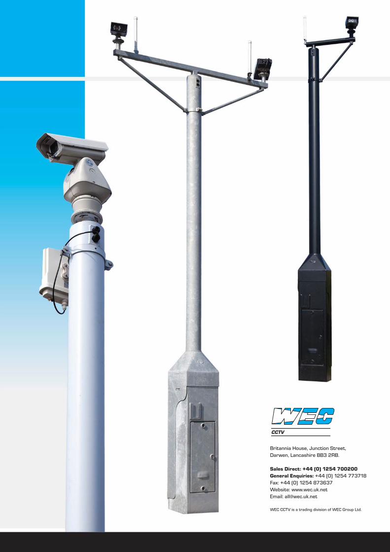
CCTV