component, deployment and package diagrams csis3600
TRANSCRIPT

Component, Deployment and Package Diagrams
CSIS3600

Partitions and Collaborations
• Creating “subsystems” or larger units• Grouping units that collaborate• May have collaboration among units or partitions• The more messages or contracts between objects,
the more likely they are in the same partition
PowerPoint Presentation for Dennis, Wixom & Tegardem Systems Analysis and Design
Copyright 2001 © John Wiley & Sons, Inc. All rights reserved.

Package
• A general construct that groups units together
• Used to reduce complexity of models
• A package diagram shows packages only
PowerPoint Presentation for Dennis, Wixom & Tegardem Systems Analysis and Design
Copyright 2001 © John Wiley & Sons, Inc. All rights reserved.
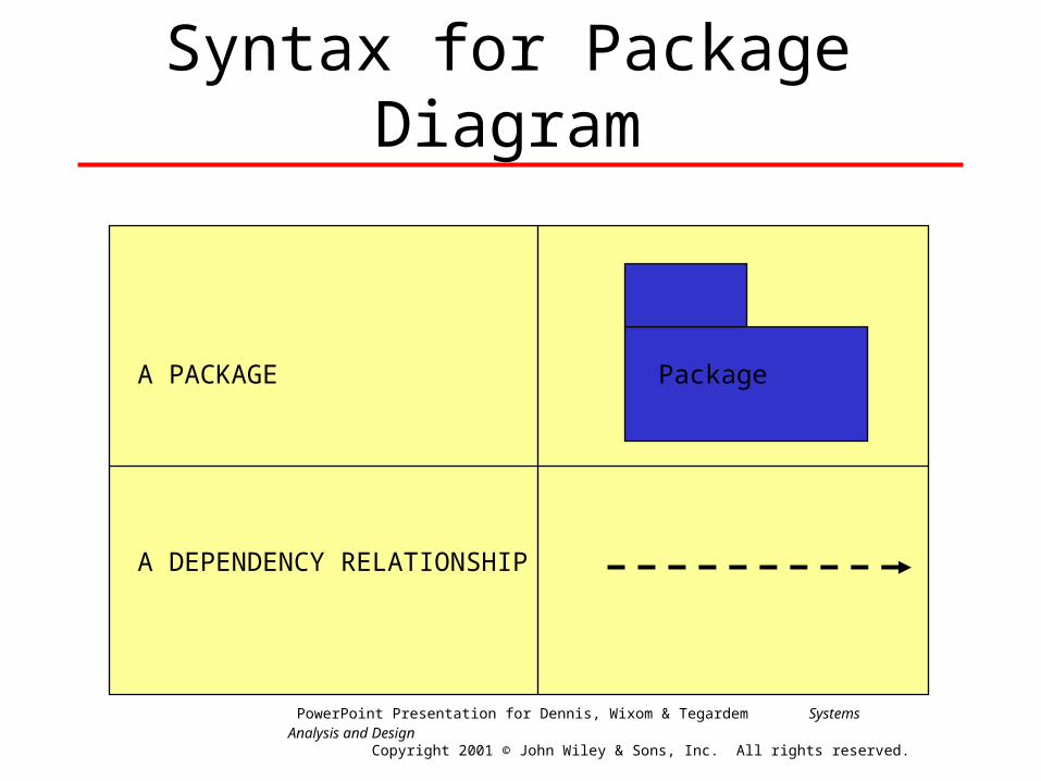
Syntax for Package Diagram
A PACKAGE Package
A DEPENDENCY RELATIONSHIP
PowerPoint Presentation for Dennis, Wixom & Tegardem Systems Analysis and Design
Copyright 2001 © John Wiley & Sons, Inc. All rights reserved.

Modification Dependency• Indicates that a change in one package could cause a change
to be required in another package.
• Example:
– A change in one method will cause the interface for all objects of this class to change. Therefore, all classes that have objects that send messages to the instances of the modified class could have to be modified.
PowerPoint Presentation for Dennis, Wixom & Tegardem Systems Analysis and Design
Copyright 2001 © John Wiley & Sons, Inc. All rights reserved.

Package Diagram of Dependency Relationships Among Layers
PowerPoint Presentation for Dennis, Wixom & Tegardem Systems Analysis and Design
Copyright 2001 © John Wiley & Sons, Inc. All rights reserved.
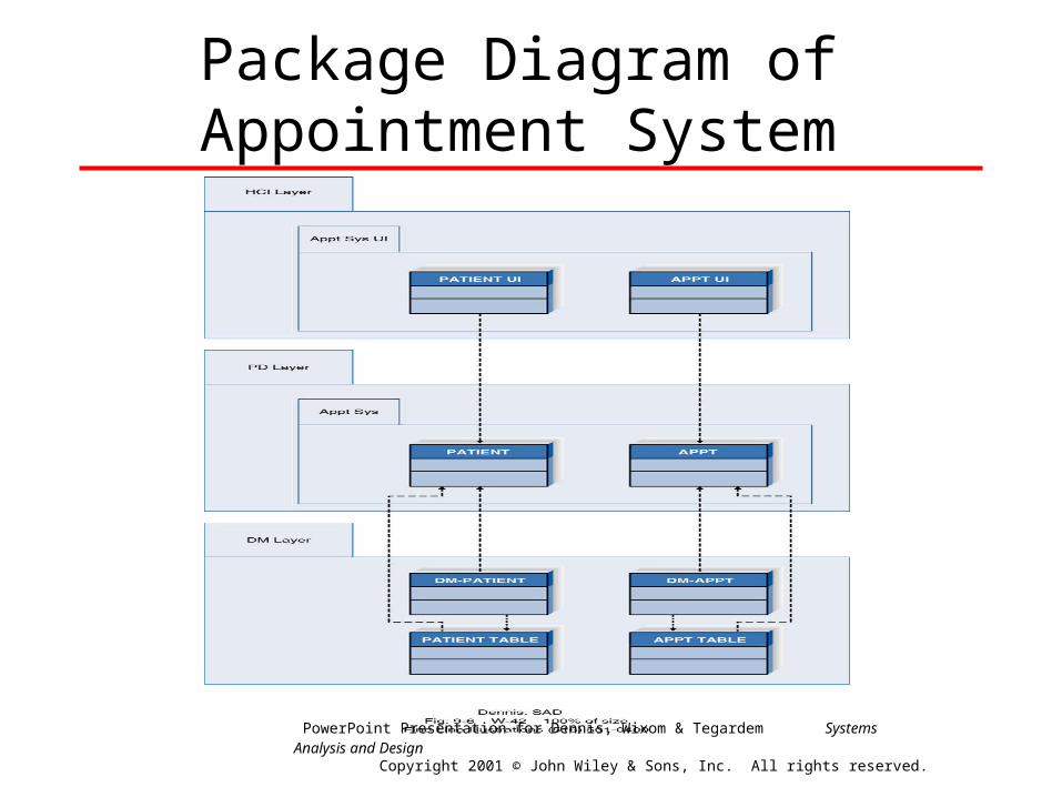
Package Diagram of Appointment System
PowerPoint Presentation for Dennis, Wixom & Tegardem Systems Analysis and Design
Copyright 2001 © John Wiley & Sons, Inc. All rights reserved.
Steps for Identifying Packages and Building Package Diagrams
• Set the context
• Cluster classes together based on shared relationships
• Model clustered classes as a package
• Identify dependency relationships among packages
• Place dependency relationships between packages
PowerPoint Presentation for Dennis, Wixom & Tegardem Systems Analysis and Design
Copyright 2001 © John Wiley & Sons, Inc. All rights reserved.

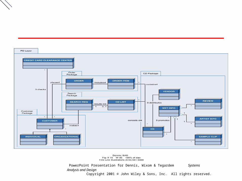
Package Diagram of the PD Layer for the Appointment System
PowerPoint Presentation for Dennis, Wixom & Tegardem Systems Analysis and Design
Copyright 2001 © John Wiley & Sons, Inc. All rights reserved.
PowerPoint Presentation for Dennis, Wixom & Tegardem Systems Analysis and Design
Copyright 2001 © John Wiley & Sons, Inc. All rights reserved.
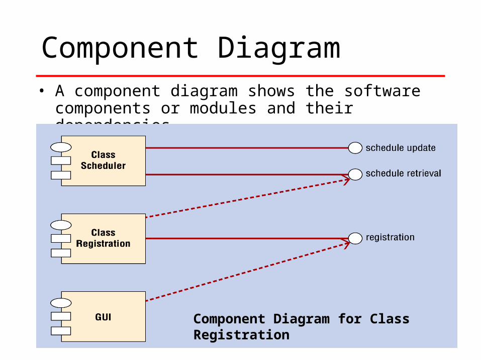
Component Diagram• A component diagram shows the software components or
modules and their dependencies.
Component Diagram for Class Registration

Symbols of the Component Diagram
• Rectangle with two smaller protruding rectangles represents a component. Components are named.
• Lollipop (line connected to a small circle) represents link to an interface.
• Dashed Arrow represents dependency from source to target.

Rules of the Component Diagram
• Components group classes into logical units of work.• These components represent source files, executable files,
dynamic link libraries, interfaces, etc.
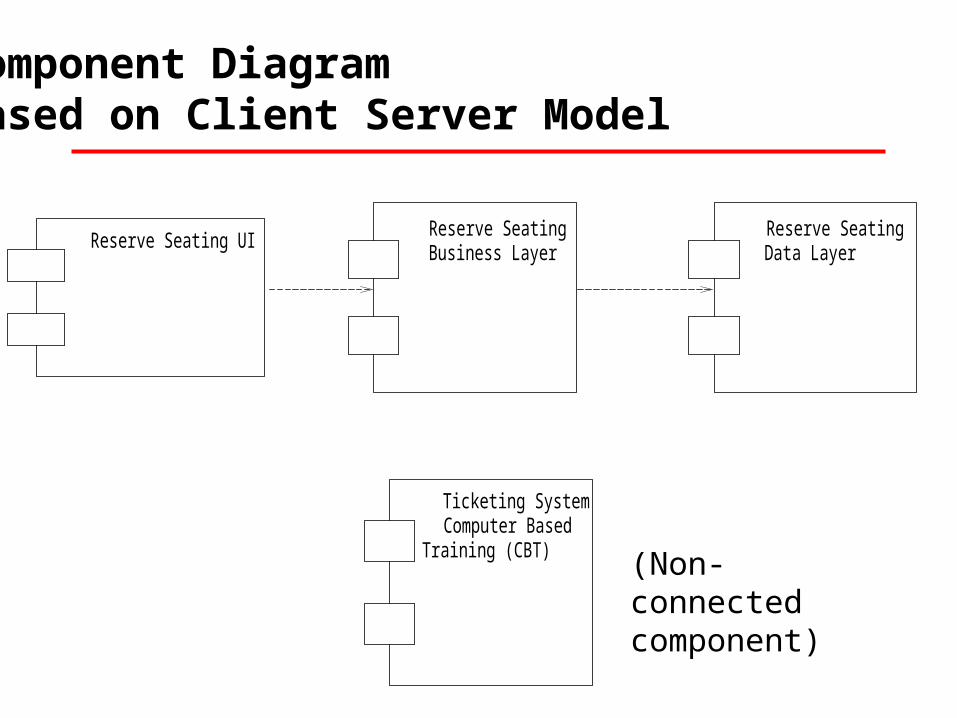
Reserve Seating UI Reserve Seating Business Layer
Reserve Seating Data Layer
Ticketing System Computer Based
Training (CBT)
Component Diagram Based on Client Server Model
(Non-connected component)
Components and Technical Design
• Component Diagram illustrates the evolving technology solution
• Loosely defined components are software modules
• The component diagram models the software component dependencies for source code, binary code and executable components
Deployment Diagram
• Deployment diagrams are used to model physical processors and devices and the components that reside on those devices
• Devices on the deployment diagram are drawn as rectangles
• Components can then be placed inside the deployment diagram

Deployment Diagram Example
Reserve Seating UI
Node 1: Client Workstations
Reserve Seating DataLayer
Node 2: Database Server
Reserve Seating Business Layer
Node 2: Application Server

Additional UML Resources
• IBM – Developer Works
– http://www-106.ibm.com/developerworks/
• Search for UML (they have tutorials on sequence diagrams, activity diagrams, etc.)
• Sequence diagrams
http://www-106.ibm.com/developerworks/library/j-jmod0508/index.html
• Activity diagrams
http://www-106.ibm.com/developerworks/library/tip-drawuml/
• UML Workbook
http://www-106.ibm.com/developerworks/java/library/j-jmodcol.html
• Rational’s UML Resources
http://www.rational.com/uml/gstart/online.jsp
• Listing of some UML tutorials
http://www.find.com.au/tutorials/programming/uml/
Quote of the Week