1 uml component and deployment diagrams. models, views, and diagrams use case diagrams use case...
Post on 21-Dec-2015
276 views
TRANSCRIPT

1
UML Component and Deployment Diagrams
Models, Views, and Diagrams
Use CaseDiagramsUse Case
DiagramsUse CaseDiagrams
ScenarioDiagramsScenario
DiagramsCollaborationDiagrams
StateDiagramsState
DiagramsComponentDiagrams
ComponentDiagramsComponent
DiagramsDeploymentDiagrams
StateDiagramsState
DiagramsObjectDiagrams
ScenarioDiagramsScenario
DiagramsStatechartDiagrams
Use CaseDiagramsUse Case
DiagramsSequenceDiagrams
StateDiagramsState
DiagramsClassDiagrams
ActivityDiagrams
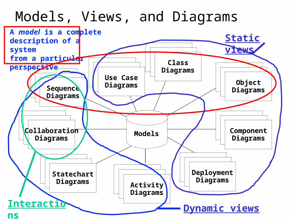
A model is a completedescription of a systemfrom a particularperspective
Models
Dynamic viewsInteractions
Static views

3
3
Diagrams
A diagram is a view into a model Presented from the aspect of a particular
stakeholder
Provides a partial representation of the system
Is semantically consistent with other views
In the UML, there are nine standard diagrams Static views: use case, class, object,
component, deployment
Dynamic views: sequence, collaboration, statechart, activity


Sequence number

8
8
Collaboration Diagram “who sends to whom”
Captures dynamic behavior (message-oriented) – not “when”

9
9
Collaboration Diagram
Captures dynamic behavior (message-oriented)
Purpose Model flow of control
Illustrate coordination of object structure and control

Example: Change Flight Itinerary (Use case description)


Sequence diagram for making a hotel reservation

Collaboration diagram for making a hotel reservation

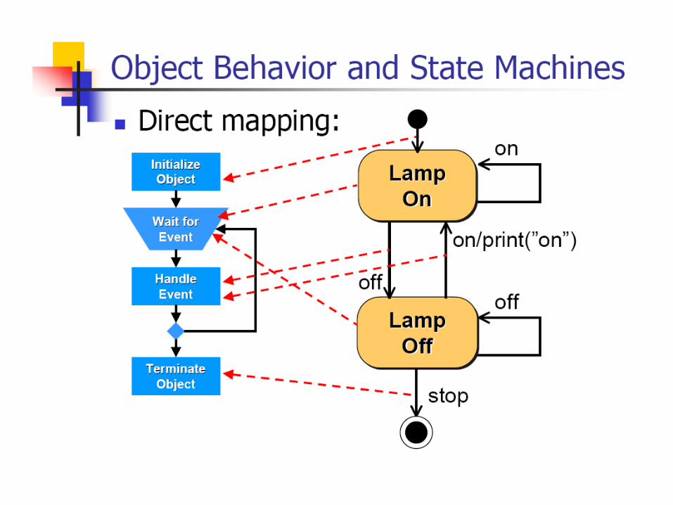
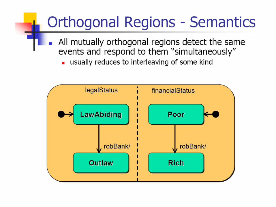
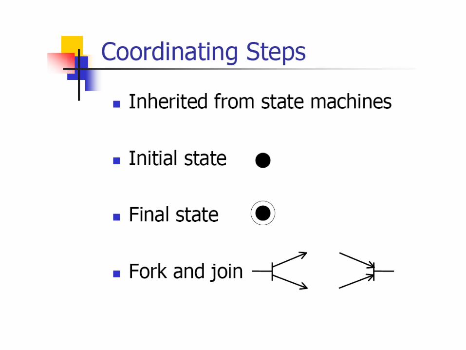
UML Statechart Diagram
Automata:


action


Statechart Example: Login part of an online banking system. Logging in consists of entering a valid social security number and personal id number, then submitting the information for validation.


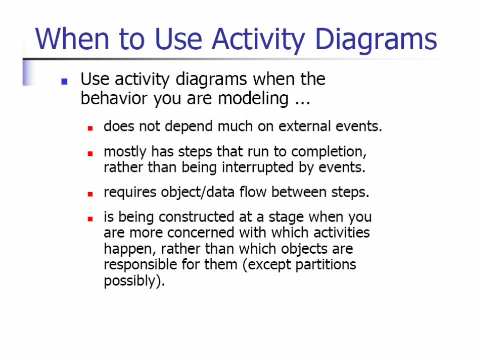
UML Activity Diagram


Example: Activity Diagram – work flow, operation
Captures dynamic behavior (activity-oriented)
Building a house
activity
Syntax not defined in UML
Semantics:
• Evaluate expression
• Send a method
• Create or destroy an object
Synchronization bars
Change of state or attribute
Parallel activities

Example Activity: “Withdraw money from an ATM.”