complete automation of future grid for optimal real-time ...knakayam/smartgrid.pdf · balancing...
TRANSCRIPT
Complete Automation of Future
Grid for Optimal Real-Time
Distribution of Renewables
Kiyoshi Nakayama, Kyle Benson,
Vahe Avagyan, Lubomir Bic, Michael Dillencourt, Nalini Venkatasubramanian, Jack Brouwer
IEEE Smart Grid Comm 2012
Making power grids intelligent
by incorporating IT technologies into a power grid
What is Smart Grid?
2
Concept
Key Concepts
Incorporate natural energies such as sunlight from the
premises like houses and factories (Renewables)
Integrate Smart Intelligent Meters with power grid
Sustainable and Reliable Autonomous Control
for Future Power Grid has been required!
Balancing problem of renewables
3
A power system is transforming itself into a smart grid
Integrating a multitude of distributed energy resources
Employs automated control systems
Essential Problem
To maximize the efficiency of distributed renewable energy
resources
Power generation from fossil fuels (diesel oils), nuclear plants,
among others wanted to be reduced
Imbalanced distribution of dispersed powers leads to blackout
This issue leads to a balancing problem of renewables
energies among dispersed power storage systems
Sustainability
4
Sustainable and reliable power distribution control in real
time becomes difficult especially in a large-scale network
Development of autonomous distributed architecture
that can allocate dispersed renewable energy resources
homogeneously is inevitable
To conduct high-reliable operation of future power distribution
networks
The amount of electricity generated by natural
energy fluctuates depending on its Intermittency
and diary change of weather conditions
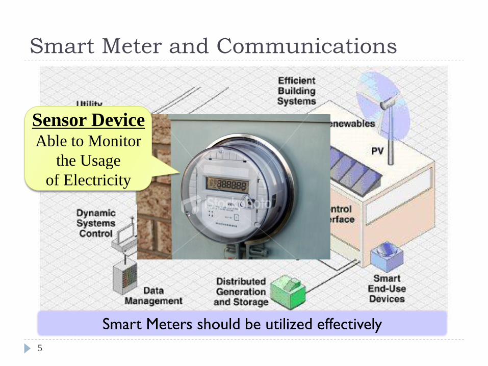
Smart Meter and Communications
5
Sensor Device Able to Monitor
the Usage
of Electricity
Smart Meters should be utilized effectively
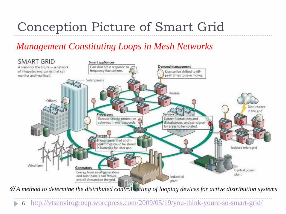
Conception Picture of Smart Grid
6
Management Constituting Loops in Mesh Networks
http://vtsenvirogroup.wordpress.com/2009/05/19/you-think-youre-so-smart-grid/
※ A method to determine the distributed control setting of looping devices for active distribution systems
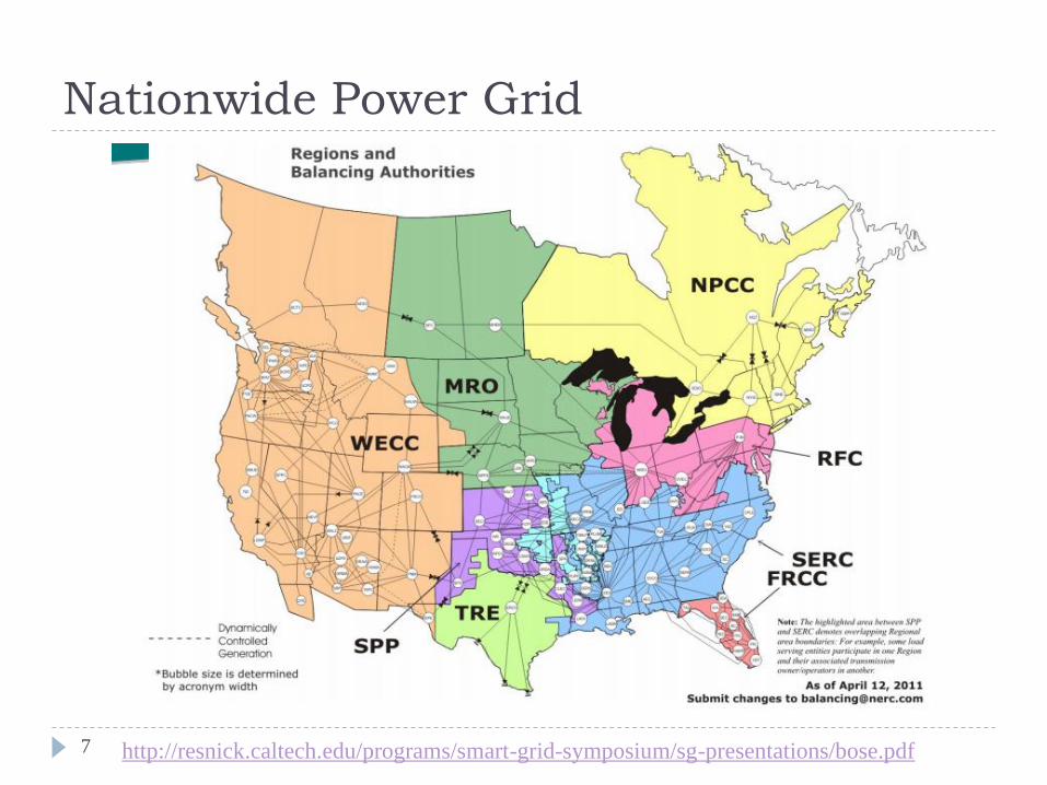
Nationwide Power Grid
7
http://resnick.caltech.edu/programs/smart-grid-symposium/sg-presentations/bose.pdf
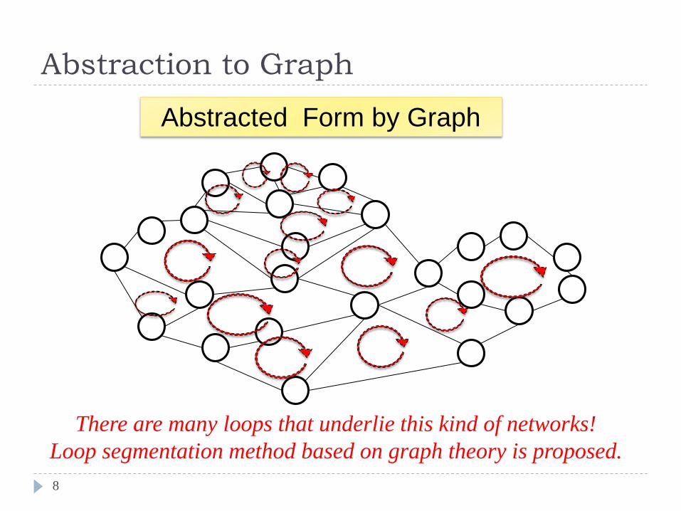
Abstraction to Graph
8
Abstracted Form by Graph
There are many loops that underlie this kind of networks!
Loop segmentation method based on graph theory is proposed.
Tie-set Graph Theory
and Distributed Control Algorithms
Since Kirchhoff’s Voltage and Current Law (KVL and KCL) in 1845
Global Optimization based on Local Optimizations
Fault Tolerance Analysis
9
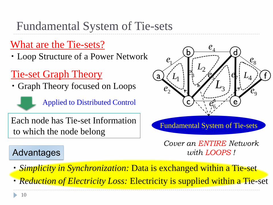
Fundamental System of Tie-sets
10
What are the Tie-sets? ・ Loop Structure of a Power Network
Tie-set Graph Theory ・ Graph Theory focused on Loops
Applied to Distributed Control
Each node has Tie-set Information
to which the node belong Fundamental System of Tie-sets
Advantages Cover an ENTIRE Network
with LOOPS !
a
b
c
d
e
f
5e
8e
6e
7e
9e
4L2L
1L
4e
・ Reduction of Electricity Loss: Electricity is supplied within a Tie-set
・ Simplicity in Synchronization: Data is exchanged within a Tie-set
1e
2e
3e
3L
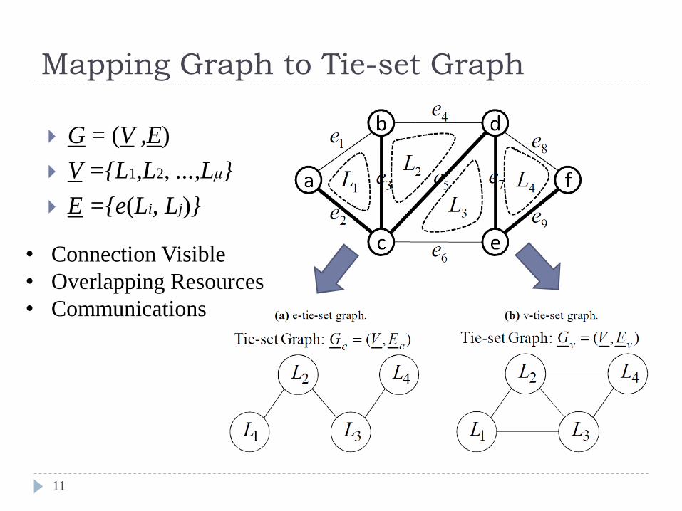
Mapping Graph to Tie-set Graph
11
G = (V ,E)
V ={L1,L2, ...,Lμ}
E ={e(Li, Lj)}
• Connection Visible
• Overlapping Resources
• Communications
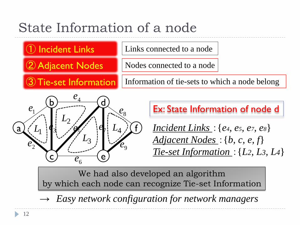
State Information of a node
12
③ Tie-set Information
① Incident Links
② Adjacent Nodes
Links connected to a node
Ex: State Information of node d
e1
Incident Links :{e4, e5, e7, e8}
Adjacent Nodes :{b, c, e, f}
Tie-set Information :{L2, L3, L4}
We had also developed an algorithm
by which each node can recognize Tie-set Information
Information of tie-sets to which a node belong
Nodes connected to a node
a
b
c
d
e
f
1e
2e
3e5e
8e
6e
7e
9e
4L
3L
2L
1L
4e
→ Easy network configuration for network managers
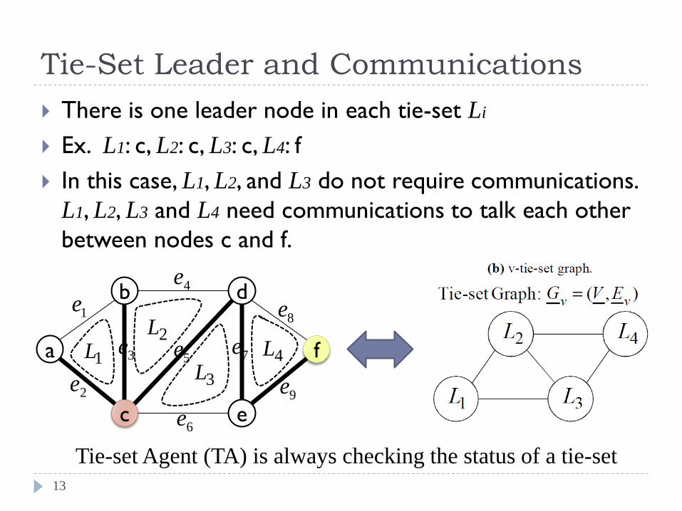
Tie-Set Leader and Communications
13
There is one leader node in each tie-set Li
Ex. L1: c, L2: c, L3: c, L4: f
In this case, L1, L2, and L3 do not require communications.
L1, L2, L3 and L4 need communications to talk each other
between nodes c and f.
a
b
c
d
e
f
1e
2e
3e5e
8e
6e
7e
9e
4L
3L
2L
1L
4e
Tie-set Agent (TA) is always checking the status of a tie-set
Optimal Real-Time Distribution
of Renewable Energy Resources
Constant Balanced Allocations of Renewables in Real Time
ORDER problem
14
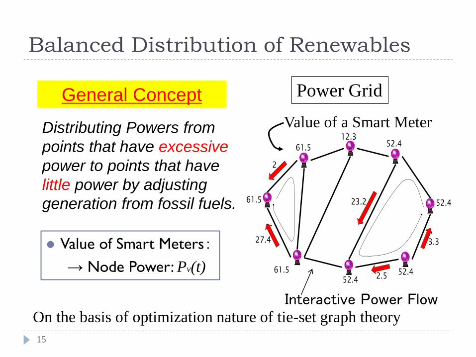
Balanced Distribution of Renewables
15
Power Grid General Concept
Value of a Smart Meter
Interactive Power Flow
Value of Smart Meters:
→ Node Power: Pv(t)
61.5 52.4
52.4
52.4
12.3
61.5
61.5
52.4
2
27.4
23.2
3.3
2.5
Distributing Powers from
points that have excessive
power to points that have
little power by adjusting
generation from fossil fuels.
On the basis of optimization nature of tie-set graph theory
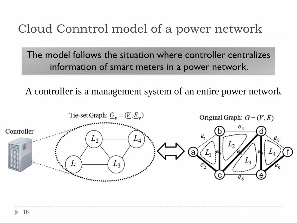
Cloud Conntrol model of a power network
16
The model follows the situation where controller centralizes
information of smart meters in a power network.
A controller is a management system of an entire power network
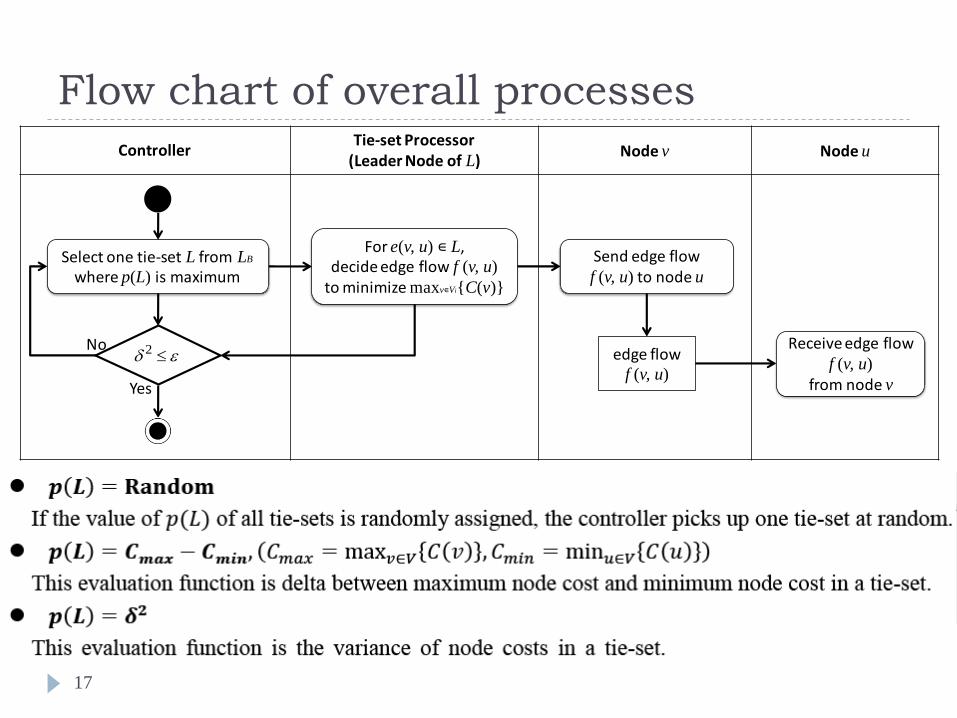
Flow chart of overall processes
17
ControllerTie-set Processor
(Leader Node of L)Node v Node u
Select one tie-set L from LB
where p(L) is maximum
Yes
No 2
For e(v, u) ∊ L, decide edge flow f (v, u)
to minimize maxv∊Vi{C(v)}
Send edge flowf (v, u) to node u
edge flowf (v, u)
Receive edge flowf (v, u)
from node v
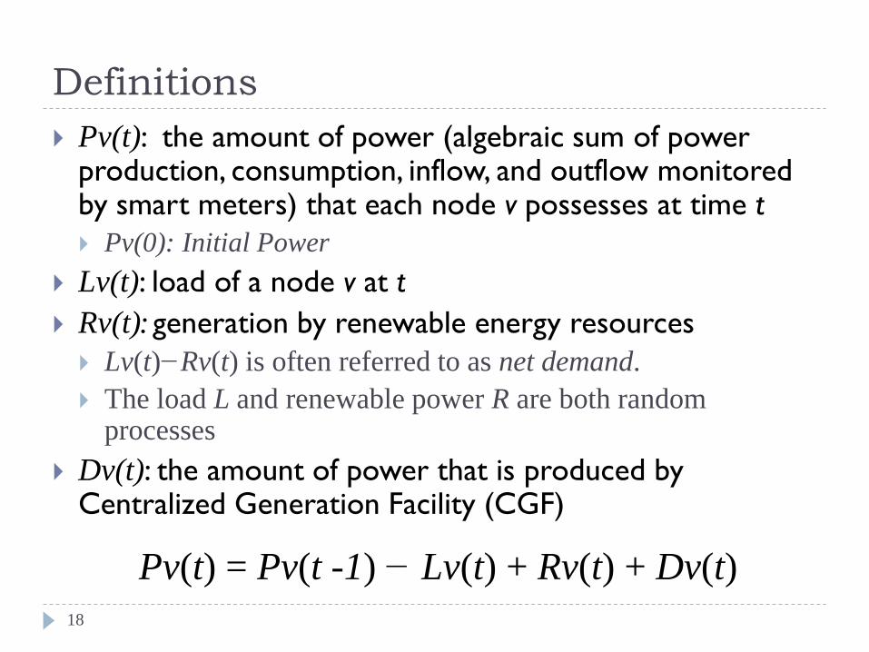
Definitions
18
Pv(t): the amount of power (algebraic sum of power production, consumption, inflow, and outflow monitored by smart meters) that each node v possesses at time t
Pv(0): Initial Power
Lv(t): load of a node v at t
Rv(t): generation by renewable energy resources
Lv(t)−Rv(t) is often referred to as net demand.
The load L and renewable power R are both random processes
Dv(t): the amount of power that is produced by Centralized Generation Facility (CGF)
Pv(t) = Pv(t -1) − Lv(t) + Rv(t) + Dv(t)
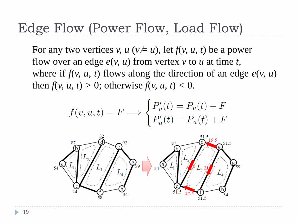
Edge Flow (Power Flow, Load Flow)
19
For any two vertices v, u (v ̸= u), let f(v, u, t) be a power
flow over an edge e(v, u) from vertex v to u at time t,
where if f(v, u, t) flows along the direction of an edge e(v, u)
then f(v, u, t) > 0; otherwise f(v, u, t) < 0.
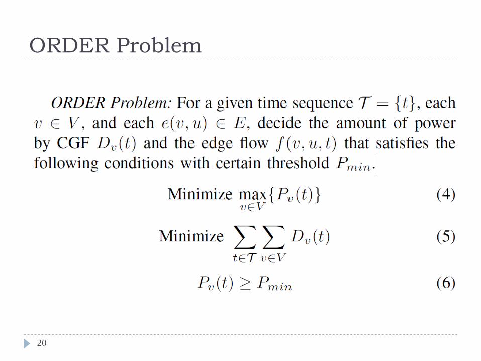
ORDER Problem
20
Autonomous Distributed Control for ORDER
Problem (1)
21
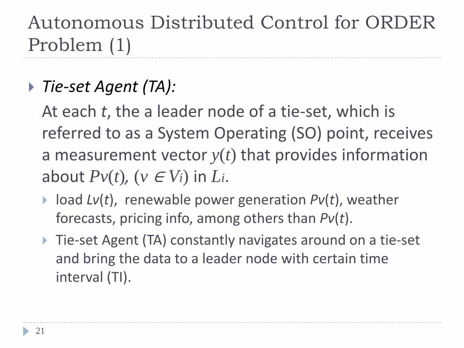
Tie-set Agent (TA):
At each t, the a leader node of a tie-set, which is referred to as a System Operating (SO) point, receives a measurement vector y(t) that provides information about Pv(t), (v ∈ Vi) in Li. load Lv(t), renewable power generation Pv(t), weather
forecasts, pricing info, among others than Pv(t).
Tie-set Agent (TA) constantly navigates around on a tie-set and bring the data to a leader node with certain time interval (TI).
Autonomous Distributed Control for ORDER
Problem (2)
22
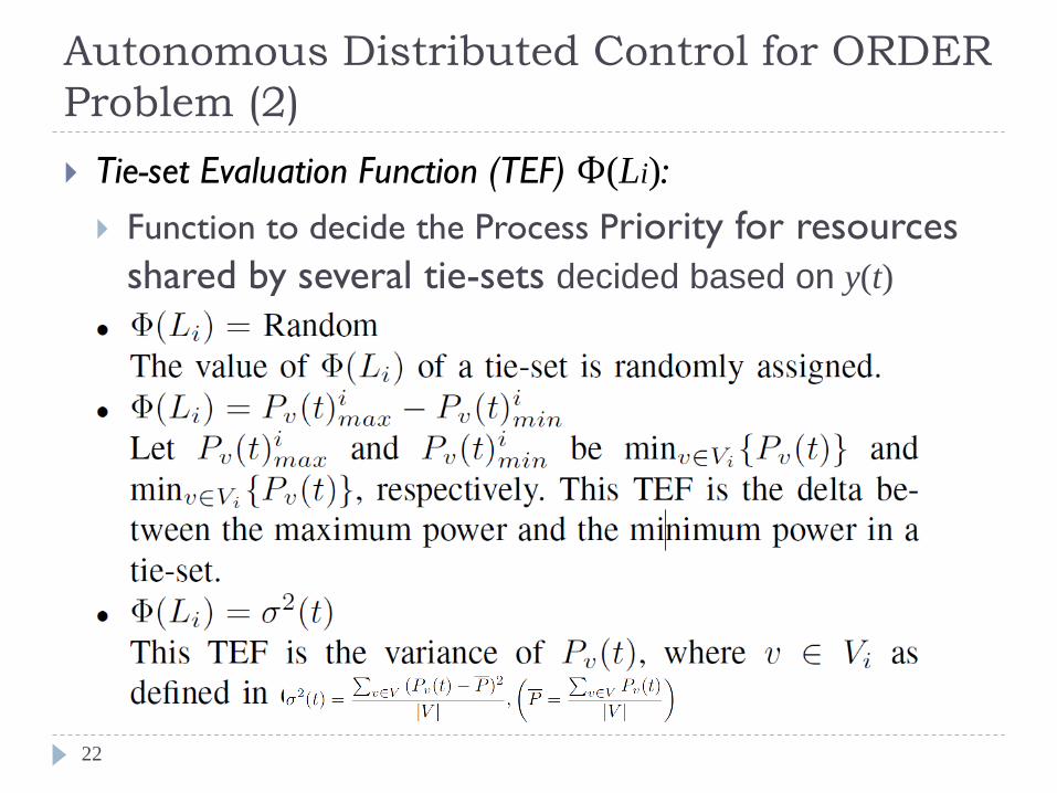
Tie-set Evaluation Function (TEF) Ф(Li):
Function to decide the Process Priority for resources
shared by several tie-sets decided based on y(t)
Autonomous Control with TEF
23
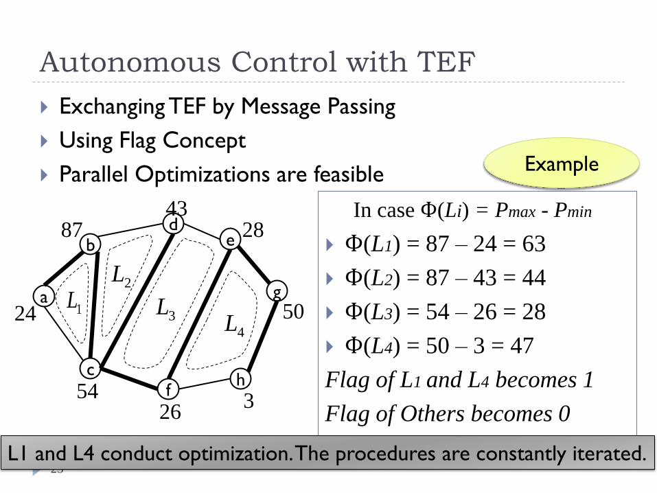
Exchanging TEF by Message Passing
Using Flag Concept
Parallel Optimizations are feasible
24 50
87
3
28
26
43
54
1L
4L
3L2L
a
f h
d e
g
c
b
Ф(L1) = 87 – 24 = 63
Ф(L2) = 87 – 43 = 44
Ф(L3) = 54 – 26 = 28
Ф(L4) = 50 – 3 = 47
Flag of L1 and L4 becomes 1
Flag of Others becomes 0
In case Ф(Li) = Pmax - Pmin
Example
L1 and L4 conduct optimization. The procedures are constantly iterated.
Distributed Optimization Algorithm
within a Tie-set
24
Distributed Optimization Algorithm
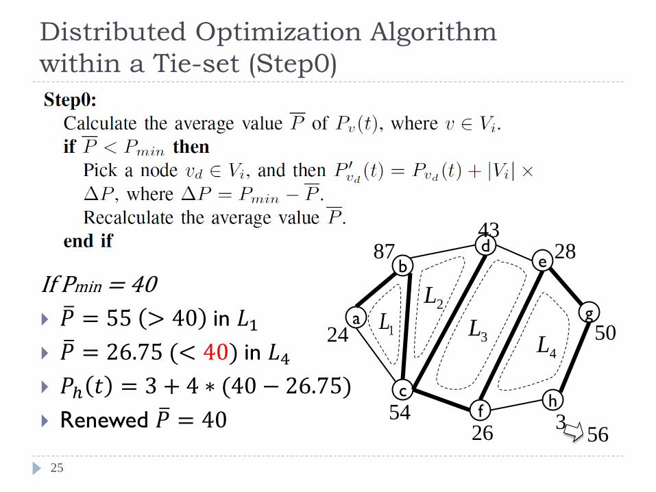
within a Tie-set (Step0)
25
If Pmin = 40
𝑃 = 55 > 40 in 𝐿1
𝑃 = 26.75 (< 40) in 𝐿4
𝑃ℎ 𝑡 = 3 + 4 ∗ (40 − 26.75)
Renewed 𝑃 = 40
24 50
87
3
28
26
43
54
1L
4L
3L2L
a
f h
d e
g
c
b
56
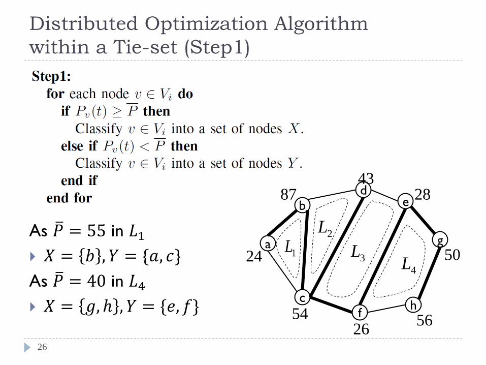
Distributed Optimization Algorithm
within a Tie-set (Step1)
26
As 𝑃 = 55 in 𝐿1
𝑋 = 𝑏 , 𝑌 = {𝑎, 𝑐}
As 𝑃 = 40 in 𝐿4
𝑋 = 𝑔, ℎ , 𝑌 = {𝑒, 𝑓}
24 50
87 28
26
43
54
1L
4L
3L2L
a
f h
d e
g
c
b
56
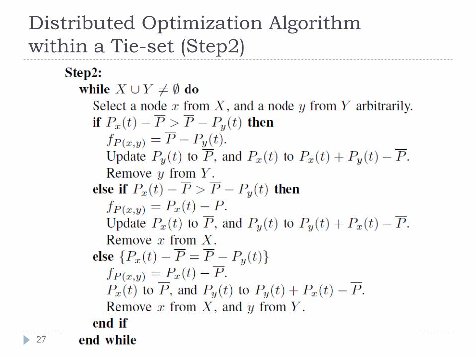
Distributed Optimization Algorithm
within a Tie-set (Step2)
27
24 50
87
56
28
26
43
54
1L
4L
3L2L
a
f h
d e
g
c
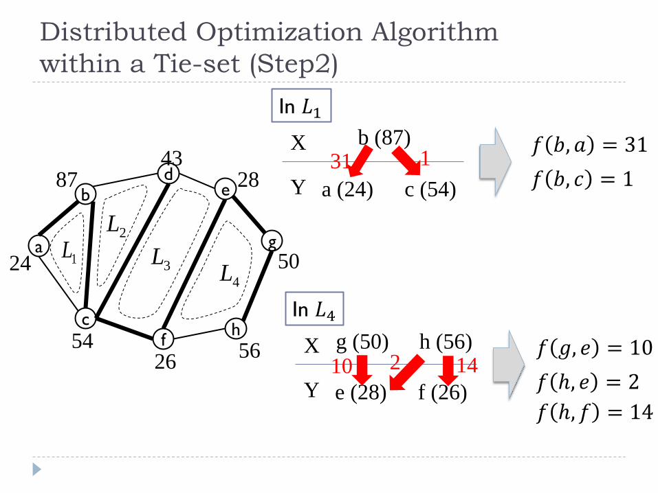
b a (24)
b (87)
c (54)
X
Y
31 1 𝑓 𝑏, 𝑎 = 31
𝑓 𝑏, 𝑐 = 1
In 𝐿1
e (28)
g (50)
f (26)
X
Y 10 14
𝑓 𝑔, 𝑒 = 10
𝑓 ℎ, 𝑒 = 2
In 𝐿4
h (56) 2
𝑓 ℎ, 𝑓 = 14
Distributed Optimization Algorithm
within a Tie-set (Step2)
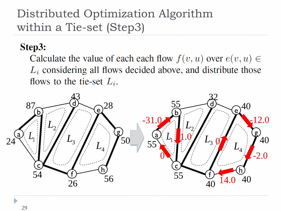
Distributed Optimization Algorithm
within a Tie-set (Step3)
29
24 50
87
56
28
26
43
54
1L
4L
3L2L
a
f h
d e
g
c
b
55 40
55
40
40
40
32
55
1L
4L
3L2L
a
f h
d e
g
c
b -12.0
0
0
-31.0
1.0
14.0
-2.0
Simulations and Experiments
30
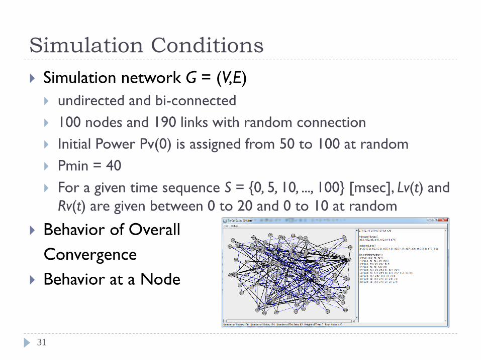
Simulation Conditions
31
Simulation network G = (V,E)
undirected and bi-connected
100 nodes and 190 links with random connection
Initial Power Pv(0) is assigned from 50 to 100 at random
Pmin = 40
For a given time sequence S = {0, 5, 10, ..., 100} [msec], Lv(t) and
Rv(t) are given between 0 to 20 and 0 to 10 at random
Behavior of Overall
Convergence
Behavior at a Node
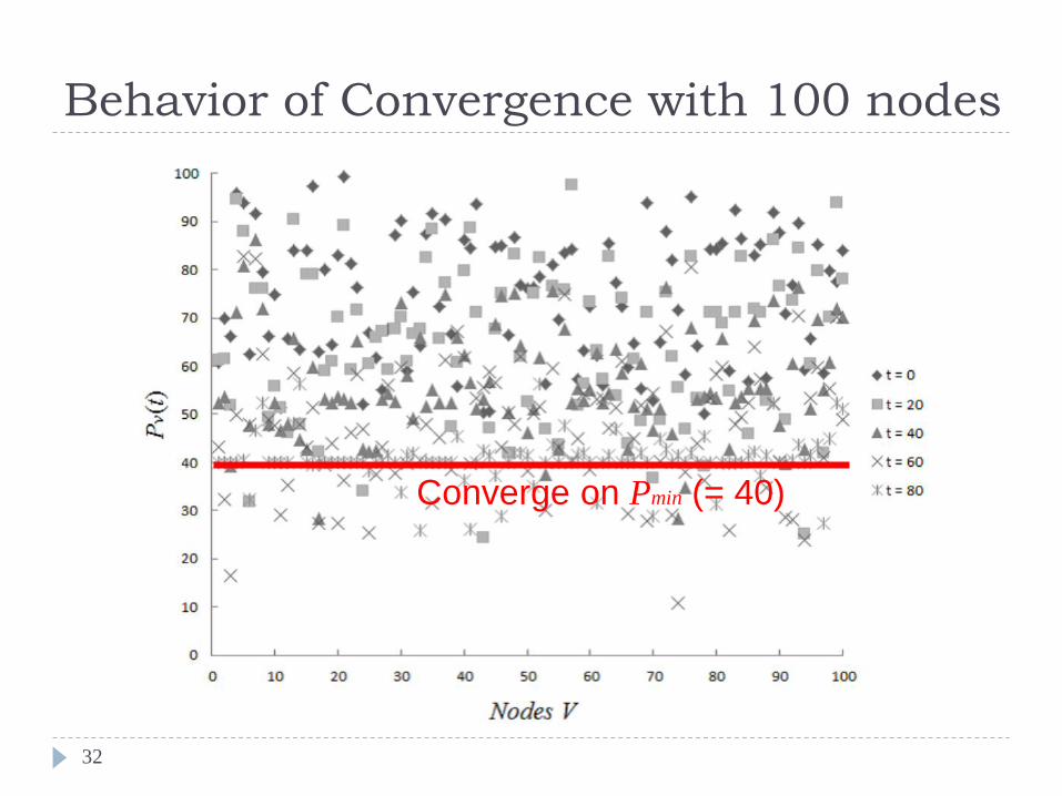
Behavior of Convergence with 100 nodes
32
Converge on Pmin (= 40)
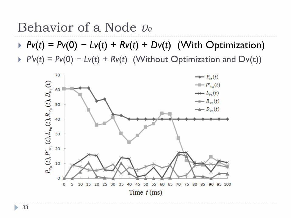
Behavior of a Node v0
33
Pv(t) = Pv(0) − Lv(t) + Rv(t) + Dv(t) (With Optimization)
P′v(t) = Pv(0) − Lv(t) + Rv(t) (Without Optimization and Dv(t))
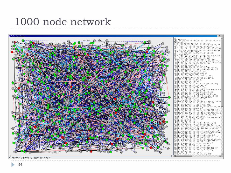
1000 node network
34
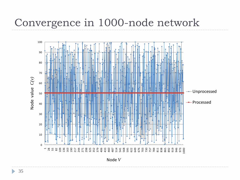
Convergence in 1000-node network
35
0
10
20
30
40
50
60
70
80
90
1001
28
55
82
10
9
13
6
16
3
19
0
21
7
24
4
27
1
29
8
32
5
35
2
37
9
40
6
43
3
46
0
48
7
51
4
54
1
56
8
59
5
62
2
64
9
67
6
70
3
73
0
75
7
78
4
81
1
83
8
86
5
89
2
91
9
94
6
97
3
10
00
Unprocessed
Processed
No
de
valu
e C
(v)
Node V
Conclusion
36
Tie-set Graph Theory and its Distributed Algorithms are introduced as a theoretical background.
Tie-set Graph Theory is the logical approach to divide a graph into a set of independent loops.
Optimal Real-Time Distribution Problem of Renewable Energy Resources (ORDER) is formulated and Autonomous Distributed Control method for ORDER is proposed.
Simulation results of one hundred-node network demonstrate the optimal distribution of renewables and thus effectiveness of the proposed method.
Future Works
37
Transmissions Loss, Conversion Loss, Error Measurement,
and characteristics of Central Generation Facilities
More Intelligent Approach
Measurement of Rate of Changes at a node or tie-set to design
time interval to conduct optimization
Computation of Pricing and Security
Pragmatic Simulations
Experiment on a larger-scale network
Evaluation of TEF and its behavior
Feed more constraints from the energy harvesting side

Thank you for your kind attention!
38