comparison of tripping characteristics for miniature ... · comparison of tripping characteristics...
TRANSCRIPT
Comparison of tripping characteristics for miniature circuit-breakers
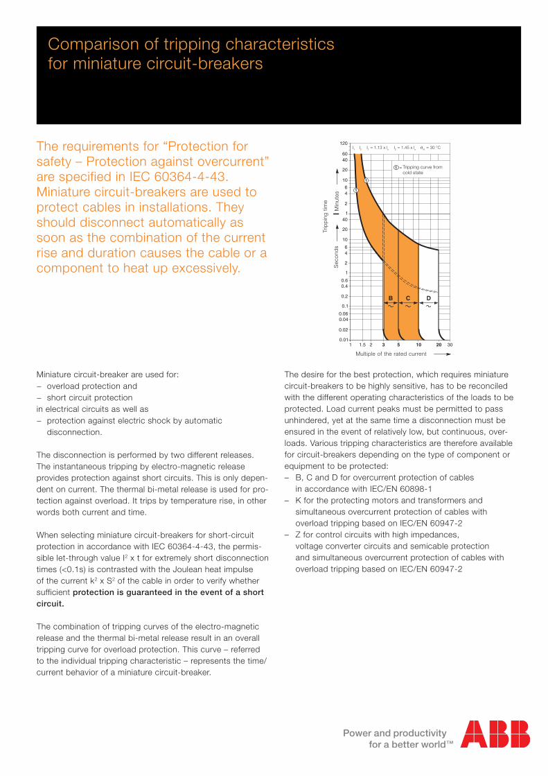
The requirements for “Protection for safety – Protection against overcurrent” are specified in IEC 60364-4-43. Miniature circuit-breakers are used to protect cables in installations. They should disconnect automatically as soon as the combination of the current rise and duration causes the cable or a component to heat up excessively.
Miniature circuit-breaker are used for: − overload protection and − short circuit protection
in electrical circuits as well as − protection against electric shock by automatic
disconnection.
The disconnection is performed by two different releases. The instantaneous tripping by electro-magnetic release provides protection against short circuits. This is only depen-dent on current. The thermal bi-metal release is used for pro-tection against overload. It trips by temperature rise, in other words both current and time.
When selecting miniature circuit-breakers for short-circuit protection in accordance with IEC 60364-4-43, the permis-sible let-through value I2 x t for extremely short disconnection times (<0.1s) is contrasted with the Joulean heat impulse of the current k2 x S2 of the cable in order to verify whether sufficient protection is guaranteed in the event of a short circuit.
The combination of tripping curves of the electro-magnetic release and the thermal bi-metal release result in an overall tripping curve for overload protection. This curve – referred to the individual tripping characteristic – represents the time/current behavior of a miniature circuit-breaker.
The desire for the best protection, which requires miniature circuit-breakers to be highly sensitive, has to be reconciled with the different operating characteristics of the loads to be protected. Load current peaks must be permitted to pass unhindered, yet at the same time a disconnection must be ensured in the event of relatively low, but continuous, over-loads. Various tripping characteristics are therefore available for circuit-breakers depending on the type of component or equipment to be protected:– B, C and D for overcurrent protection of cables in accordance with IEC/EN 60898-1– K for the protecting motors and transformers and simultaneous overcurrent protection of cables with overload tripping based on IEC/EN 60947-2– Z for control circuits with high impedances, voltage converter circuits and semicable protection and simultaneous overcurrent protection of cables with overload tripping based on IEC/EN 60947-2
Vielfaches des Bemessungsstromes
Aus
lsez
eit
Sek
unde
nM
inut
en
1 2 3 5 10
6040
20
10
64
2
140
20
10
64
2
1
0.60.4
0.2
0.1
0.060.04
0.02
0.01
B
20
120
= Grenzkennlinie aus dem1 kalten Zustand
C
1
D
1
1.5
I2 = 1.45 x InI1 = 1.13 x In R= 30ß C
30
JI1 I2 JRI1 I2 I1 = 1.13 x ln I2 = 1.45 x ln JR = 30 °C
Trip
pin
g tim
e
Sec
ond
sM
inut
es
Multiple of the rated current
Tripping curve from cold state

2 2CDC400002D0201
Prospective short-circuit current IK/A gL fuse Circuit-breaker
Let-
thro
ugh
I2 t /
A2 s
Fig. 2 Load limit curve for PVC-insulated cables
1
2
3
4
Area of complete heat dissipation with conti-nuous current Iz Permissible operating temperature 70 °C (PVC)
Area of limited heat dissipation in the event of overload I2 ≤ 1.45 x Iz
Area without heat dissipation for a maximum short circuit duration of 5s I2t = constant, permissible short circuit temperature 160 °C
With a disconnection time of < 0.1s, the I2t of the miniature circuit-breaker must be less than k2 · S2 of the cable (k = material value in accordance with IEC /HD 60364-4-43;S = cable cross section in mm2)
Iz 1,45 Iz 10 Iz 100 Iz IzI k = Materialwert nach DIN VDE 0100
Teil 540S = Leiterquerschnitt in mm2
Bei Ausschaltzeit < 0,1s muß I2tdes Sicherungsautomaten kleinersein als k2 · S2 der Leitung
Bereich ohne Wärmeableitungbei max. Kurzschlußdauer 5s;I2t = konstantzul. Kurzschlußßtemperatur 160 ˚C
Bereich begrenzter Wärme-ableitung bei ÜberlastI2≤ 1,45 x Iz
0,1 s
5 s
1 h
t
20 Jahre
Bereich vollkommener Wärme-ableitung bei Dauerstrom Iz
zul. Betriebstemperatur 70 ˚C
Iz 1.45 Iz 10 Iz 100 IzIIz
20years
1 h
5 sec
0.1 sec
t
2
1
3
4
Cu cable, PVC-insulatedmm2
2.5
1.5
1.0
0.75
Max. permitted I2t valuesA2s82,600
29,700
13,200
7,400
Fig. 1 Let.-through energy I2t
Protection against short-circuitsFigure 1 shows typical let-through or I2t values of overcurrent circuit-breakers. In the case of S201-B16 miniature circuit-breaker, this causes the let-through energy to be limited to approx. 20,000 A2s if a prospective short-circuit current iK = 6 kA occurs. This value is far less than 29,700 A
2, meaning
PVC-insulated Cu cables with a cross-section of 1.5 mm2 can be protected in the event of a short-circuit.
Overload protection in accordance with IEC 60364-4-43For protection against overload, the protective device must be selected based on the current carrying capacity Iz of the cable:Ib ≤ In ≤ Iz (1)I2 ≤ 1.45 x Iz (2)
Ib = Design current of a circuitIn = Rated current of the protective deviceIz = Current carrying capacity of the cable in accordance with IEC/HD 60364-5-52I2 = Current ensuring effective operation in the conventional time of the protective device
50, 63 A
32, 40 A
20, 25 A
16 A
10, 13 A
6 A
B, CIn =
102 6 8 103 2 3 4 6
105
8
6
4
3
2
104
8
6
4
3
2
103

2CDC400002D0201 3
Service life of PVC-insulated cables
according to the Arrhenius equation
Cable temperature Service life
70 ˚C 20.0 years
90 ˚C 2.5 years
100 ˚C 1.0 year
IEC 60364-4-43In individual cases, conditions (1) and (2) may not guarantee complete protection in accordance with the rules as aforesaid may not assure protection in certain cases, for example where sustained overcurrents less than I2 occur. In such cases, consideration should be given to selecting a cable with a larger cross-section area.
The general aim is to use the selected characteristic to protect a cable in accordance with its load capacity limit as shown in figure 2.
Protection against overloadFurthermore, protection devices with I2 values close to the rated current In can increase the effectiveness of overload protection significantly. Please refer in these cases to K- or Z-characteristic with I2 = 1,2 x In.
Vielfaches des Bemessungsstromes
Aus
lsez
eit
Sek
unde
nM
inut
en
1 2 3 5 8 10
6040
20
10
64
2
140
20
10
64
2
1
0.60.4
0.2
0.1
0.060.04
0.02
0.01
B
14 20 30
120I2 = 1.2 x InI1 = 1.05 x In = 20ß C
= Grenzkennlinie aus dem1 kalten Zustand
C
K
Z
1
1
I2 = 1.45 x InI1 = 1.13 x In = 30ß C
1.5
RJ
RJ
D
JR
JR
Temperature of PVC-insulated cables
at overload
Load Cable temperature*
1.0 x In 70 ˚C
1.2 x In 86 ˚C
1.45 x In 116 ˚C
* 90 % of the temperature value is reached from operating temperature after 5 minutes.
Multiple of the rated current
Trip
pin
g tim
e
Sec
ond
sM
inut
es
I1 = 1.05 x ln I2 = 1.2 x ln JR = 20 °C (K, Z)
I1 = 1.13 x ln I2 = 1.45 x ln JR = 30 °C (B, C, D)
Tripping curve from cold state

4 2CDC400002D0201
Comparison of tripping characteristics “Z” and “B”
24 V DC control circuitsIn order to achieve the best possible protection of sensitive devices, such as contacts or prefabricated cables of sensors/limit switches, the instantane-ous tripping must clear even low short-circuit currents within milliseconds.
The maximum cable lengths in relation to loop resistance must not be ex-ceeded. Taking account of various parameters, the maximum cable lengths could be as follows:1.5 mm
2, two-wire, Cu:
– MCB B6 max. 10 m– MCB Z2 max. 47 m– MCB Z6 max. 18 m
Due to the low instantaneous tripping current, the maximum cable lengths can be realized by using the Z characte-ristic.
NoteWith direct current, the tripping values of the electromagnetic releases are increased by a factor of 1.5.
Protection against overloadAs stated before it is obvious that tripping characteristic “Z” provides better protection during operation and is easier to choose when planning.
1 21.5 3 6 8 10 15 20 30
Vielfaches des Bemessungsstromes
Aus
lsez
eit
Sek
unde
nM
inut
en
6040
20
10
64
2
140
20
10
64
2
1
0.60.4
0.2
0.1
0.060.04
0.02
0.01
B
120I2 = 1.2 x InI1 = 1.05 x In = 20ß C
= Grenzkennlinie aus dem1 kalten Zustand
Z
1
I2 = 1.45 x InI1 = 1.13 x In = 30ß C
5
1
RJ
RJ
JR
JR
Temperature of PVC-insulated cables
at overload
Load Cable temperature*
1.0 x In 70 ˚C
1.2 x In 86 ˚C
1.45 x In 116 ˚C
Service life of PVC-insulated cables
using the Arrhenius equation
Cable temperature Service life
70 ˚C 20.0 years
90 ˚C 2.5 years
100 ˚C 1.0 year
* 90 % of the temperature value is reached from operating temperature after 5 minutes.
Multiple of the rated current
Trip
pin
g tim
e
Sec
ond
sM
inut
es
I1 = 1.05 x ln I2 = 1.2 x ln JR = 20 °C (Z)
I1 = 1.13 x ln I2 = 1.45 x ln JR = 30 °C (B)
Tripping curve from cold state

2CDC400002D0201 5
Comparison of tripping characteristics “C” and “K”
“K” solves the conflict of service conti-nuity in the event of peak currents and rapid disconnection in the event of a short-circuit.
In circuits where inrush currents or starting current peaks can occur due to motors, chargers, welding trans-formers, etc., tripping characteristic “K” has proven to be successful for more than 70 years.
Current peaks of up to 10 · In do not lead to unintentional disconnection. Tripping characteristic “C” only with-stands current peaks of up to 5 · In.
NoteWith direct current, the tripping values of the electromagnetic releases are increased by a factor of 1.5.
Vielfaches des Bemessungsstromes
Aus
lsez
eit
Sek
unde
nM
inut
en
1 2 3 5 8 10
6040
20
10
64
2
140
20
10
64
2
1
0.60.4
0.2
0.1
0.060.04
0.02
0.0114
120I2 = 1.2 x InI1 = 1.05 x In = 20ß C
= Grenzkennlinie aus dem1 kalten Zustand
C
K
1
I2 = 1.45 x InI1 = 1.13 x In = 30ß C
1.5 4
1
20 30
RJ
RJ
JR
JR
Protection against overloadAs stated before it is obvious that tripping characteristic “K” provides better protection during operation and is easier to choose.
Temperature of PVC-insulated cables
at overload
Load Cable temperature*
1.0 x In 70 ˚C
1.2 x In 86 ˚C
1.45 x In 116 ˚C
Service life of PVC-insulated cables
using the Arrhenius equation
Cable temperature Service life
70 ˚C 20.0 years
90 ˚C 2.5 years
100 ˚C 1.0 year
* 90 % of the temperature value is reached from operating temperature after 5 minutes.
Multiple of the rated current
Trip
pin
g tim
e
Sec
ond
sM
inut
es
I1 = 1.05 x ln I2 = 1.2 x ln JR = 20 °C (K)
I1 = 1.13 x ln I2 = 1.45 x ln JR = 30 °C (C)
Tripping curve from cold state

2CDC400002D0201 6
“K” solves the conflict of service conti-nuity in the event of peak currents and rapid switch off in the event of a short circuit.
Tripping characteristic “K” trips at the latest at 14 · In in <0.1 seconds. By contrast, tripping characteristic “D” disconnect the device at 20 · In in <0.1 seconds, which could be a disadvan-tage both with regard to the loop re-sistance and for cable protection in the range from 10-20 x In.
Example: A socket is protected with a D16 miniature circuit-breaker. A minimum short-circuit current ≥320 A must be ensured in order to comply with the dis-connection condition of ≤0.4 s for pro-tection against electric shock.
NoteWith direct current, the tripping values of the electromagnetic releases are increased by a factor of 1.5.
Comparison of tripping characteristics “K” and “D”
Vielfaches des Bemessungsstromes
Aus
lsez
eit
Sek
unde
nM
inut
en
1 2 3 5 8 10
6040
20
10
64
2
140
20
10
64
2
1
0.60.4
0.2
0.1
0.060.04
0.02
0.0114 20 30
120I2 = 1.2 x InI1 = 1.05 x In = 20ß C
= Grenzkennlinie aus dem1 kalten Zustand
K
1
D
1
I2 = 1.45 x InI1 = 1.13 x In = 30ß C
1.5 4 6
RJ
RJ
(K)JR
JR
Protection against overloadAs stated before it is obvious that tripping characteristic “K” provides better protection during operation and is easier to choose.
Temperature of PVC-insulated cables
at overload
Load Cable temperature*
1.0 x In 70 ˚C
1.2 x In 86 ˚C
1.45 x In 116 ˚C
Service life of PVC-insulated cables
according to the Arrhenius equation
Cable temperature Service life
70 ˚C 20.0 years
90 ˚C 2.5 years
100 ˚C 1.0 year
* 90 % of the temperature value is reached from operating temperature after 5 minutes.
6 2CDC400002D0104
Multiple of the rated current
Trip
pin
g tim
e
Sec
ond
sM
inut
es
I1 = 1.05 x ln I2 = 1.2 x ln JR = 20 °C (K)
I1 = 1.13 x ln I2 = 1.45 x ln JR = 30 °C (D)
Tripping curve from cold state

2CDC400002D0201 7
Vielfaches des Bemessungsstromes
Aus
lsez
eit
Sek
unde
nM
inut
en
1 2 3 5 10
6040
20
10
64
2
140
20
10
64
2
1
0.60.4
0.2
0.1
0.060.04
0.02
0.01
B
20
120
= Grenzkennlinie aus dem1 kalten Zustand
C
1
D
1
1.5
I2 = 1.45 x InI1 = 1.13 x In R= 30ß C
30
JI1 I2
Vielfaches des Bemessungsstromes
Aus
lsez
eit
Sek
unde
nM
inut
en
1 2 3 5 8
6040
20
10
64
2
140
20
10
64
2
1
0.60.4
0.2
0.1
0.060.04
0.02
0.0114
120I2 = 1.2 x InI1 = 1.05 x In = 20ß C
KZ
1
1
1.5 4 6 20 30
RJ
= Grenzkennlinie aus dem1 kalten Zustand
10
Compared with tripping characteristics “B”, “C” and “D”, “K” and “Z” provide better protection during operation and is easier to choose.
Assignment– B, C and D for overcurrent protection of cables in accordance with IEC/EN 60898-1– K for protecting windings in motors and transformers and simultaneous overcurrent protection of cables– Z for control circuits with high impedances, voltage converter circuits and semiconductor protection and simultaneous overcurrent protection of cables
JR
Tripping characteristics B, C, D, Z, K
Tripping characteristics B, C, D Tripping characteristics K, Z in accordance with IEC/EN 60898-1 in accordance with IEC/EN 60947-2 Constructional requirements for MCBs for Constructional requirements for MCBs.household installations and similar purposes.
I1 I2 I1 = 1.13 x ln I2 = 1.45 x ln JR = 30 °C I1 = 1.05 x ln I2 = 1.2 x ln JR = 20 °C
Tripping curve from cold state
Tripping curve from cold state

8 2CDC400002D0201
Other criteria when selecting miniature circuit breakers
In order to protect a circuit optimally, additional considera-tions and constraints must be considered when selecting the miniature circuit-breakers.
Deviating ambient temperatureFor installations of miniature circuit-breakers at other tem-peratures than the reference value, derating factors have to be considered. The rated value of the current of a miniature circuit-breaker refers to a reference ambient temperature of 30 °C for miniature circuit-breakers with the characteristics B, C and D and 20 °C for miniature circuit-breakers with the characteristics K and Z. If the ambient temperature is higher, the maximum operating currents are reduced by approx. 6 % per +10 °C temperature difference. For precise calculations and extremely high or low ambient temperatures, reference tables must be consulted.
Influence of adjacent devicesIf several miniature circuit-breakers are installed directly side by side with high load on all poles, a correction factor has to be applied to the rated current (see table). If distance pieces are used, the factor is not to be considered.
No. of adjacent devices Factor F
1 1
2, 3 0.9
4, 5 0.8
≥ 6 0.75
Tripping characteristicsAcc. to Tripping
characte- ristics
Rated current
Thermal release 1) Electromagnetic release 2)
In
Currents:conventionalnon-trippingcurrentI1
conventionaltrippingcurrentI2
Tripping time Range of instantaneous tripping
Tripping time
IEC/EN 60898-1 B 6 to 63 A 1.13 · In1.45 · In
> 1 h
< 1 h 3)
3 · In5 · In
0.1 ... 45 s (In ≤ 32 A)/0.1 ... 90 s (In > 32 A)
< 0.1 sC 0.5 to 63 A 1.13 · In
1.45 · In
> 1 h
< 1 h 3)
5 · In10 · In
0.1 ... 15 s (In ≤ 32 A)/0.1 ... 30 s (In > 32 A)
< 0.1 sD 0.5 to 63 A 1.13 · In
1.45 · In
> 1 h
< 1 h 3)
10 · In20 · In
0.1 ... 4 s (In ≤ 32 A)/0.1 ... 8 s (In > 32 A)
< 0.1 sIEC/EN 60947-2 K 0.5 to 63 A 1.05 · In
1.2 · In
> 1 h
< 1 h 3)
10 · In14 · In
> 0.2 s
< 0.2 sZ 0.5 to 63 A 1.05 · In
1.2 · In
> 1 h
< 1 h 3)
2 · In3 · In
> 0.2 s
< 0.2 s
1) The thermal releases are calibrated to a nominal reference ambient temperature; for B, C, D the reference value is 30 °C, for K and Z the reference value is 20 °C. In the case of higher ambient temperatures, the current values fall by approx. 6 % for each 10 K temperature rise.2) The indicated tripping values of electromagnetic tripping devices apply to a frequency of 50/60 Hz. The thermal release operates independent of frequency.3) As from operating temperature (after I1 > 1h)

2CDC400002D0201 9
Miniature circuit breakers for cable and equipment protection and their fields of application
As a selective group or upstream MCB
1
1
Fields of application S 200 S 200 P S 220 S 800 S 700 S 400
S 200 M S 200 U/UP S 500 HV S 750 (DR) SMISSLINE
S 200 UDC S 800 PV WT 63
S 280 UC
Industrial networks
690 V AC S 220 S 800
1000 V AC S 500 HV
Motor protection, transformer S 200-K S 200 P-K S 220-K S 800-K S 700-K S 400 M-K
S 200 M-K S 280 UC-K S 800-D WT 63 S 400 M-D
S 750 DR-K
UPS 250 V DC
to
Photovoltaics 1200 V DC
S 280 UC S 800 UC S 400 M-UC C
S 800 PV
Semicable pro-
tection
Control
circuits
S 200-Z
S 200 M-Z
S 200 P-Z S 400 M-UC Z
24 V DC
Selectivity S 700
S 750 (DR)
Isolating function in accordance S 200 S 200 P S 220 S 800 S 700 S 400
with IEC 60364-5-537 S 200 M S 750 (DR) S 400 M
USA, Canada 480 V AC S 200 UP
489 240 V AC S 200 U
60 V DC S 200 UDC
USA, Canada 600 V AC S 220
1077 480 V AC S 200 M S 200 P
60 V DC S 200 M S 200 P
500 V DC S 280 UC
Marine classifications S 200 S 200 P S 800 S 700 (GL) S 400 M
GL LRS S 200 M
BV DNV
Rated switching 6 000 max. 25,000 max. 10,000 max. 50,000 25,000 6,000
capacity Icn/A 10 000 10 000
(230/400 V AC)
In/A ≤ 63 0.5 ... 63 ≤ 63 ≤ 125 ≤ 100 ≤ 63

Bro
chur
e nu
mbe
r 2
CD
C 4
00 0
02 D
0201
(01.
13-p
df) ABB STOTZ-KONTAKT GmbH
PO Box 10 16 8069006 Heidelberg, GermanyPhone: +49 (0) 6221 7 01–0 Fax: +49 (0) 6221 7 01–13 25 E-mail: [email protected]
www.abb.de/stotzkontakt
Contact
Note:We reserve the right to make technical changes or modify the contents of this document without prior notice. With regard to purchase orders, the agreed particulars shall prevail. ABB AG does not accept any responsibility whatsoever for potential errors or possible lack of information in this document.
We reserve all rights in this document and in the subject matter and illustrations contained therein. Any reproduction, disclosure to third parties or utilization of its contents – in whole or in parts – is forbidden without prior written consent of ABB AG.
Copyright© 2013 ABB All rights reserved