comparison of electric dipole and magnetic loop antennas ... · and a variety of antennas for...
TRANSCRIPT
Comparison of electric dipole and magnetic loop antennas for excitingwhistler modes
R. L. Stenzel and J. M. UrrutiaDepartment of Physics and Astronomy, University of California, Los Angeles, California 90095-1547, USA
(Received 20 June 2016; accepted 25 July 2016; published online 23 August 2016)
The excitation of low frequency whistler modes from different antennas has been investigatedexperimentally in a large laboratory plasma. One antenna consists of a linear electric dipoleoriented across the uniform ambient magnetic field B0. The other antenna is an elongated loop withdipole moment parallel to B0. Both antennas are driven by the same rf generator which produces arf burst well below the electron cyclotron frequency. The antenna currents as well as the wavemagnetic fields from each antenna are measured. Both the antenna currents and the wave fields ofthe loop antenna exceed that of the electric dipole by two orders of magnitude. The conclusion isthat loop antennas are far superior to dipole antennas for exciting large amplitude whistler modes, aresult important for active wave experiments in space plasmas. Published by AIP Publishing.[http://dx.doi.org/10.1063/1.4960666]
I. INTRODUCTION
The excitation of low frequency whistler modes is ofimportance in space and laboratory plasmas. The presentinterest in space plasmas is to effectively scatter energeticelectrons in velocity space. Such electrons are naturally pre-sent in the radiation belts1,2 and can be man-made by highaltitude nuclear explosions.3 In both cases, the electronsshorten the lifetime of satellites. Wave-particle interactionsare known to precipitate electrons.4,5 In the laboratory, lowfrequency whistler modes are extensively studied for produc-ing dense rf plasmas. These whistler modes are usuallycalled helicons6,7 and first observed in solid state plasmas.8
Helicons find applications in plasma processing, for propul-sion as thrusters on satellites, and heating and rf current drivein magnetic fusion devices.9–11 There are also several large-diameter laboratory devices where the basic physics ofwhistler modes has been studied.12–15 Linear and nonlinearwhistler modes have been studied in detail. Radiationpatterns of different antennas have been explored, showingresonance cones and thermal ducting phenomena.16–20
Nonlinear whistlers with wave magnetic fields exceeding theambient field have been observed.21 Helicon waves havebeen produced in unbounded uniform plasmas.22 Their fieldrotation produces an orbital angular momentum which canlead to new wave-particle and wave-wave interaction by atransverse Doppler shift.
Whistler modes are usually excited with electric dipoleantennas in active space experiments.23–25 Early experimentswith loop antennas were discontinued due to difficult with thedeployment of large loops.26 On the other hand, large ampli-tude helicon waves are always excited with magnetic loopantennas.27 Thus, the present work addresses the differencebetween electric and magnetic antennas under identical exper-imental conditions. The radiation resistance is determinedfrom first principles from the measured antenna currents andthe radiated power. The electric dipole has a much smallerradiation resistance than the magnetic loop, but more
important is the ratio of antenna currents. For an insulatedelectric dipole, it is given by the capacitive current throughthe sheath; for a loop antenna, the current is determined by theloop inductance and applied voltage. For the same appliedvoltage, the current, hence radiated power, is over two ordersof magnitude larger for a loop compared to a dipole.
The paper is organized as follows: After describing theexperimental setup and measurement procedure in SectionII, the observations and evaluations are presented in SectionIII in several subsections. The findings are summarized inSection IV.
II. EXPERIMENTAL SETUP AND DATA EVALUATIONS
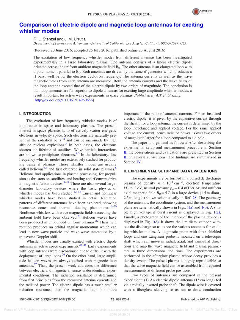
The experiments are performed in a pulsed dc dischargeplasma of density ne ’ 1011 cm!3, electron temperaturekTe ’ 2 eV, neutral pressure pn¼ 0.4 mTorr Ar, and uniformaxial magnetic field B0¼ 5 G in a large device (1.5 m diam.,2.5 m length) shown schematically in Ref. 28. The geometryof the antennas, the coordinate system, and the measurementplane are schematically shown in Figs. 1(a) and 1(b). A sim-ple high voltage rf burst circuit is displayed in Fig. 1(c).Finally, a photograph of the interior of the plasma device isdisplayed in Fig. 1(d). It shows the 1 m diam. cathode with-out the discharge so as to see the various antennas for excit-ing whistler modes. A diagnostic probe with three shieldedloops and one Langmuir probe is mounted on a telescopicshaft which can move in radial, axial, and azimuthal direc-tions and map the wave magnetic field and plasma parame-ters in three dimensions and time. The experiments areperformed in the afterglow plasma whose decay provides adensity sweep. The pulsed plasma is highly reproducible sothat the wave magnetic field can be assembled from repeatedmeasurements at different probe positions.
Two types of antennas are compared in the presentexperiment: (1) An electric dipole antenna (15 cm long) fedvia a radially inserted probe shaft. The dipole wire is coveredwith a fiberglass sleeving so as not to draw conduction
1070-664X/2016/23(8)/082120/8/$30.00 Published by AIP Publishing.23, 082120-1
PHYSICS OF PLASMAS 23, 082120 (2016)
Reuse of AIP Publishing content is subject to the terms at: https://publishing.aip.org/authors/rights-and-permissions. Downloaded to IP: 128.97.23.76 On: Sat, 17 Sep
2016 01:25:01
currents. It is also floating with respect to the chamberground. In order to excite waves along the axial dc magneticfield, the dipole is aligned perpendicular to B0. (2) An elon-gated magnetic loop antenna is formed by two parallel wires(4 cm spacing, 20 cm length) closed by semicircles at theend. Although magnetic loops are mostly circular, the elon-gated loop has nearly no field variation along the wire, andits vertical translation can approximately produce planewaves by field superposition.29 At the chosen frequency(f ’ 5 MHz), the antenna lengths are small compared to thefree-space wavelength, such that the voltage and current arenearly constant along the wires. Thus, the elongated mag-netic loop is not a folded electric dipole. The dipole momentof the elongated loop is aligned along B0. For the presentparameters (cyclotron frequency fc ’ 14 MHz, plasma fre-quency fp ’ 3000 MHz), the transverse antenna lengths arecomparable to the axial whistler wavelength (kz ’ 15;…; 20cm). The analog probe signals are digitized with a four-channel digital oscilloscope with 10 ns time resolution. Sincewe are interested in the wave field produced by plasma cur-rents, the vacuum field of the antenna is recorded on alter-nate shots and subtracted from the total field measured in thepresence of plasma.
The pulsed discharge is repeated at a rate of 1 Hz, andthe rf waveform is triggered at the same afterglow time andaveraged over 10 shots so as to improve the signal-to-noise
ratio. The antennas are energized with two types of rf wave-forms: A sequence of repeated rf tone bursts of duration20 ls covering most of the afterglow. The signal is phase-locked to resolve the time dependence for all rf bursts. Thewaveform is produced by a function generator and amplifiedby a broadband amplifier of moderate output power (8 W). Itis used for wave excitation by the magnetic loop, but it is toosmall to excite waves with the electric dipole. Therefore, ahigh power signal is produced with an L-C ringing circuit. Itconsists of a fast switching transistor which discharges acharged capacitor (1 nF,<1000 V) into an inductor to pro-duce a damped ringing waveform at f ’ 4:5 MHz. The burstgenerator can deliver 1 A into a 1 kX resistor, hence can sup-ply 1 kW into a matched load. However, no matching circuitis used so as to maintain a sharp rise time of the rf burstwhich is useful for comparing group and phase velocities.The sequence of phase-locked ringing rf bursts is applied viaa balanced rf transformer to the electric dipole.
For comparison, the same signal generator is applied toboth antennas but separately. The antenna currents are mea-sured with a Rogowski coil. The short duration of the largeamplitude rf burst avoids electron heating and thermal duct-ing.17 Furthermore, we have verified that the total waveamplitude, B ¼ ðB2
x þ B2y þ B2
z Þ1=2, is proportional to the
antenna current, which confirms linear wave excitation.
III. EXPERIMENTAL RESULTS
A. Currents and voltages on the dipole and loopantenna
Antennas inside the plasma have to be fed by a transmis-sion line. These consist of two parallel wires inside a stain-less steel tube (6 mm diam., ’1 m length) carrying currentsin opposite directions. The last 30 cm are not covered by thegrounded tube. Currents (I) and voltages (V) are measured atthe outside end of the shaft. However, an identical dipoleantenna has been used in air to measure I and V at theantenna feed points. There is negligible voltage variation ona ’1 m transmission line when the free-space wavelength isc/f¼ 60 m.
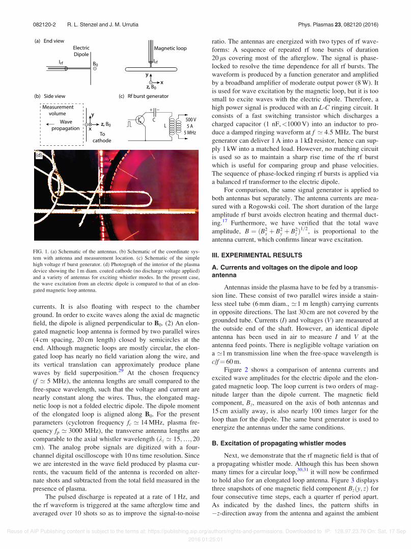
Figure 2 shows a comparison of antenna currents andexcited wave amplitudes for the electric dipole and the elon-gated magnetic loop. The loop current is two orders of mag-nitude larger than the dipole current. The magnetic fieldcomponent, Bz, measured on the axis of both antennas and15 cm axially away, is also nearly 100 times larger for theloop than for the dipole. The same burst generator is used toenergize the antennas under the same conditions.
B. Excitation of propagating whistler modes
Next, we demonstrate that the rf magnetic field is that ofa propagating whistler mode. Although this has been shownmany times for a circular loop,30,31 it will now be confirmedto hold also for an elongated loop antenna. Figure 3 displaysthree snapshots of one magnetic field component Bzðy; zÞ forfour consecutive time steps, each a quarter rf period apart.As indicated by the dashed lines, the pattern shifts in!z-direction away from the antenna and against the ambient
FIG. 1. (a) Schematic of the antennas. (b) Schematic of the coordinate sys-tem with antenna and measurement location. (c) Schematic of the simplehigh voltage rf burst generator. (d) Photograph of the interior of the plasmadevice showing the 1 m diam. coated cathode (no discharge voltage applied)and a variety of antennas for exciting whistler modes. In the present case,the wave excitation from an electric dipole is compared to that of an elon-gated magnetic loop antenna.
082120-2 R. L. Stenzel and J. M. Urrutia Phys. Plasmas 23, 082120 (2016)
Reuse of AIP Publishing content is subject to the terms at: https://publishing.aip.org/authors/rights-and-permissions. Downloaded to IP: 128.97.23.76 On: Sat, 17 Sep
2016 01:25:01
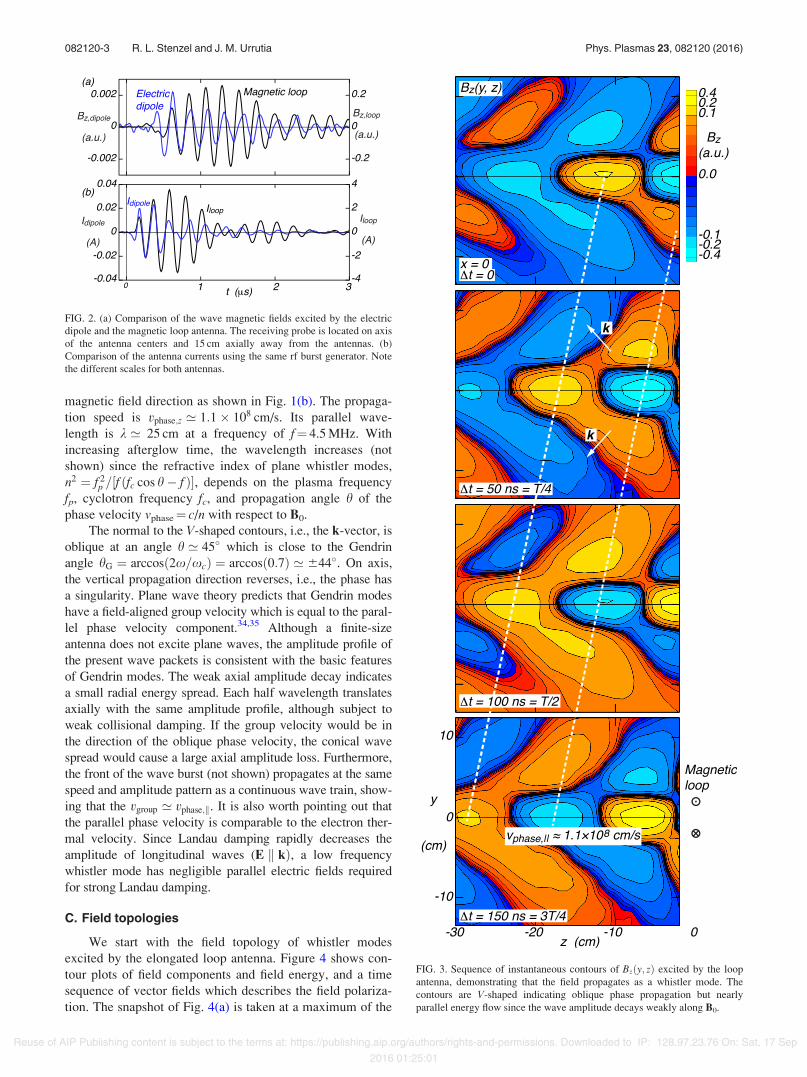
magnetic field direction as shown in Fig. 1(b). The propaga-tion speed is vphase;z ’ 1:1& 108 cm/s. Its parallel wave-length is k ’ 25 cm at a frequency of f¼ 4.5 MHz. Withincreasing afterglow time, the wavelength increases (notshown) since the refractive index of plane whistler modes,n2 ¼ f 2
p =½f ðfc cos h! f Þ(, depends on the plasma frequencyfp, cyclotron frequency fc, and propagation angle h of thephase velocity vphase¼ c/n with respect to B0.
The normal to the V-shaped contours, i.e., the k-vector, isoblique at an angle h ’ 45) which is close to the Gendrinangle hG ¼ arccosð2x=xcÞ ¼ arccosð0:7Þ ’ 644). On axis,the vertical propagation direction reverses, i.e., the phase hasa singularity. Plane wave theory predicts that Gendrin modeshave a field-aligned group velocity which is equal to the paral-lel phase velocity component.34,35 Although a finite-sizeantenna does not excite plane waves, the amplitude profile ofthe present wave packets is consistent with the basic featuresof Gendrin modes. The weak axial amplitude decay indicatesa small radial energy spread. Each half wavelength translatesaxially with the same amplitude profile, although subject toweak collisional damping. If the group velocity would be inthe direction of the oblique phase velocity, the conical wavespread would cause a large axial amplitude loss. Furthermore,the front of the wave burst (not shown) propagates at the samespeed and amplitude pattern as a continuous wave train, show-ing that the vgroup ’ vphase;k. It is also worth pointing out thatthe parallel phase velocity is comparable to the electron ther-mal velocity. Since Landau damping rapidly decreases theamplitude of longitudinal waves (E k kÞ, a low frequencywhistler mode has negligible parallel electric fields requiredfor strong Landau damping.
C. Field topologies
We start with the field topology of whistler modesexcited by the elongated loop antenna. Figure 4 shows con-tour plots of field components and field energy, and a timesequence of vector fields which describes the field polariza-tion. The snapshot of Fig. 4(a) is taken at a maximum of the
FIG. 2. (a) Comparison of the wave magnetic fields excited by the electricdipole and the magnetic loop antenna. The receiving probe is located on axisof the antenna centers and 15 cm axially away from the antennas. (b)Comparison of the antenna currents using the same rf burst generator. Notethe different scales for both antennas.
FIG. 3. Sequence of instantaneous contours of Bzðy; zÞ excited by the loopantenna, demonstrating that the field propagates as a whistler mode. Thecontours are V-shaped indicating oblique phase propagation but nearlyparallel energy flow since the wave amplitude decays weakly along B0.
082120-3 R. L. Stenzel and J. M. Urrutia Phys. Plasmas 23, 082120 (2016)
Reuse of AIP Publishing content is subject to the terms at: https://publishing.aip.org/authors/rights-and-permissions. Downloaded to IP: 128.97.23.76 On: Sat, 17 Sep
2016 01:25:01

axial field component Bz. It mirrors the vacuum field of theelongated loop antenna. Figure 4(b) displays the transversecomponent Bx at the same time. These indicate antiparallelfields surrounding the axial field. The By component is notshown since at this time it is negligible in the center regionexcept at the ends of the wave packet.
Figure 4(c) shows the distribution of the wave energydensity, B2 ¼ B2
x þ B2y þ B2
z . It peaks along the center of thewave packet, dominated by large B2
z , and is still large at topand bottom where B2
x dominates. It remains large at the hori-zontal ends where B2
y dominates while B2x ’ 0 and B2
z ’ 0.The field topology changes in time as shown in Fig. 4(d)
by three snapshots of vector fields (Bx, By) in the x–y plane.Starting with the time Dt ¼ 0, corresponding to the contourplots, one can recognize transverse fields enclosing the axialfield component Bz. A quarter rf period later (Dt ¼ 50 ns)when both Bz and Bx vanish, By dominates in the central
region. Finally, after a half rf period later (Dt ¼ 100 ns), bothBz and Bx peak but with reverse polarity, while By is negligi-ble. Following each vector in time shows that it rotates in aright handed sense with respect to B0, irrespective of propaga-tion direction (here against B0).
We also note that at a constant axial propagation speed(vz¼ z/t) and weak damping, the axial field dependence isproportional to the temporal field dependence. One canthen visualize the phase fronts in 3D space and constructfield lines in 3D (not shown). This yields the field topologywhich can be described by a flattened and inclined vor-tex.36 The spiraling field lines of a whistler vortex have anegative magnetic helicity for propagation against B0. Thiscan be seen by the left-handed linkage of the transversefield (Bx, By) with the axial field Bz. If the loop was circu-lar, the field could also be described as an m¼ 0 heliconmode.37
FIG. 4. Topology of a whistler wave packet excited by an elongated magnetic loop antenna. (a) Contour plot of Bzðx; yÞ at z¼ 15 cm from the antenna at a timeof positive field maximum on axis of the antenna. The same display for (b) Bxðx; yÞ and (c) jBjðx; yÞ. (d) Vector fields of ðBx;ByÞðx; yÞ at three different timeswhich show a right-hand circular field polarization characteristic of whistler modes. The field topology resembles that of a elongated m¼ 0 helicon mode32 ora whistler vortex.33
082120-4 R. L. Stenzel and J. M. Urrutia Phys. Plasmas 23, 082120 (2016)
Reuse of AIP Publishing content is subject to the terms at: https://publishing.aip.org/authors/rights-and-permissions. Downloaded to IP: 128.97.23.76 On: Sat, 17 Sep
2016 01:25:01
The field topology of the electric dipole is more compli-cated than that of the loop. In free space, both the electricfield and the magnetic field form a spherical wave in the far-zone with radial Poynting’s vector S ¼ E&H. In plasma,the energy of a low frequency whistler flows predominantlyalong B0, is mainly carried by the wave magnetic field, theelectric field is mainly perpendicular to B0, and produceselectron Hall currents. Thus, one can expect the dipole waveexcitation in plasmas to be quite different than in air.
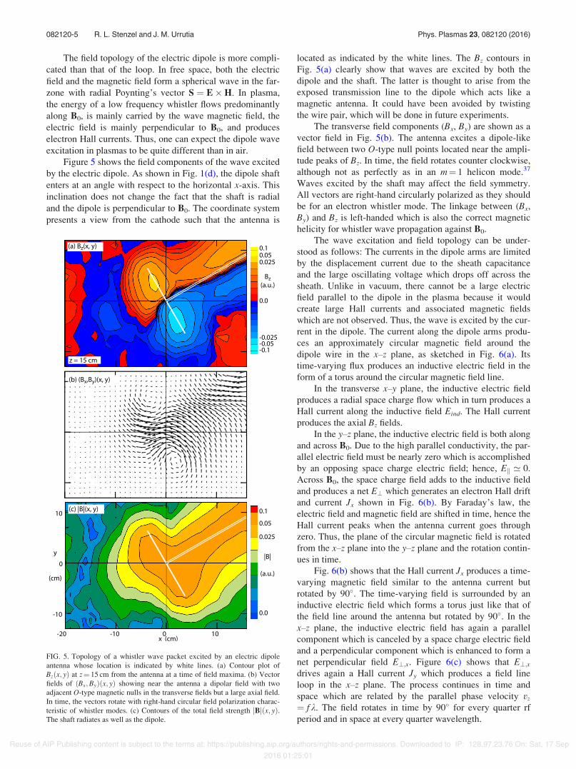
Figure 5 shows the field components of the wave excitedby the electric dipole. As shown in Fig. 1(d), the dipole shaftenters at an angle with respect to the horizontal x-axis. Thisinclination does not change the fact that the shaft is radialand the dipole is perpendicular to B0. The coordinate systempresents a view from the cathode such that the antenna is
located as indicated by the white lines. The Bz contours inFig. 5(a) clearly show that waves are excited by both thedipole and the shaft. The latter is thought to arise from theexposed transmission line to the dipole which acts like amagnetic antenna. It could have been avoided by twistingthe wire pair, which will be done in future experiments.
The transverse field components (Bx, By) are shown as avector field in Fig. 5(b). The antenna excites a dipole-likefield between two O-type null points located near the ampli-tude peaks of Bz. In time, the field rotates counter clockwise,although not as perfectly as in an m¼ 1 helicon mode.37
Waves excited by the shaft may affect the field symmetry.All vectors are right-hand circularly polarized as they shouldbe for an electron whistler mode. The linkage between (Bx,By) and Bz is left-handed which is also the correct magnetichelicity for whistler wave propagation against B0.
The wave excitation and field topology can be under-stood as follows: The currents in the dipole arms are limitedby the displacement current due to the sheath capacitanceand the large oscillating voltage which drops off across thesheath. Unlike in vacuum, there cannot be a large electricfield parallel to the dipole in the plasma because it wouldcreate large Hall currents and associated magnetic fieldswhich are not observed. Thus, the wave is excited by the cur-rent in the dipole. The current along the dipole arms produ-ces an approximately circular magnetic field around thedipole wire in the x–z plane, as sketched in Fig. 6(a). Itstime-varying flux produces an inductive electric field in theform of a torus around the circular magnetic field line.
In the transverse x–y plane, the inductive electric fieldproduces a radial space charge flow which in turn produces aHall current along the inductive field Eind. The Hall currentproduces the axial Bz fields.
In the y–z plane, the inductive electric field is both alongand across B0. Due to the high parallel conductivity, the par-allel electric field must be nearly zero which is accomplishedby an opposing space charge electric field; hence, Ek ’ 0.Across B0, the space charge field adds to the inductive fieldand produces a net E? which generates an electron Hall driftand current Jx shown in Fig. 6(b). By Faraday’s law, theelectric field and magnetic field are shifted in time, hence theHall current peaks when the antenna current goes throughzero. Thus, the plane of the circular magnetic field is rotatedfrom the x–z plane into the y–z plane and the rotation contin-ues in time.
Fig. 6(b) shows that the Hall current Jx produces a time-varying magnetic field similar to the antenna current butrotated by 90). The time-varying field is surrounded by aninductive electric field which forms a torus just like that ofthe field line around the antenna but rotated by 90). In thex–z plane, the inductive electric field has again a parallelcomponent which is canceled by a space charge electric fieldand a perpendicular component which is enhanced to form anet perpendicular field E?;x. Figure 6(c) shows that E?;xdrives again a Hall current Jy which produces a field lineloop in the x–z plane. The process continues in time andspace which are related by the parallel phase velocity vz
¼ fk. The field rotates in time by 90) for every quarter rfperiod and in space at every quarter wavelength.
FIG. 5. Topology of a whistler wave packet excited by an electric dipoleantenna whose location is indicated by white lines. (a) Contour plot ofBzðx; yÞ at z¼ 15 cm from the antenna at a time of field maxima. (b) Vectorfields of ðBx;ByÞðx; yÞ showing near the antenna a dipolar field with twoadjacent O-type magnetic nulls in the transverse fields but a large axial field.In time, the vectors rotate with right-hand circular field polarization charac-teristic of whistler modes. (c) Contours of the total field strength jBjðx; yÞ.The shaft radiates as well as the dipole.
082120-5 R. L. Stenzel and J. M. Urrutia Phys. Plasmas 23, 082120 (2016)
Reuse of AIP Publishing content is subject to the terms at: https://publishing.aip.org/authors/rights-and-permissions. Downloaded to IP: 128.97.23.76 On: Sat, 17 Sep
2016 01:25:01
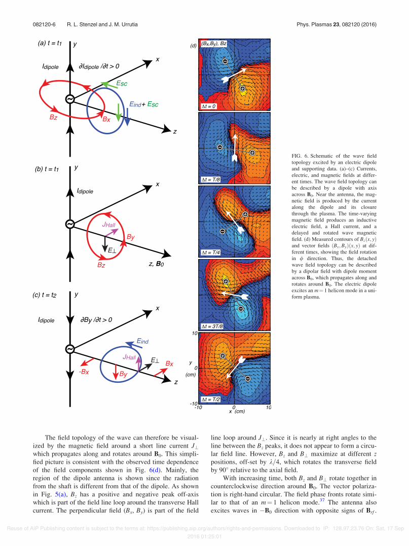
The field topology of the wave can therefore be visual-ized by the magnetic field around a short line current J?which propagates along and rotates around B0. This simpli-fied picture is consistent with the observed time dependenceof the field components shown in Fig. 6(d). Mainly, theregion of the dipole antenna is shown since the radiationfrom the shaft is different from that of the dipole. As shownin Fig. 5(a), Bz has a positive and negative peak off-axiswhich is part of the field line loop around the transverse Hallcurrent. The perpendicular field (Bx, By) is part of the field
line loop around J?. Since it is nearly at right angles to theline between the Bz peaks, it does not appear to form a circu-lar field line. However, Bz and B? maximize at different zpositions, off-set by k=4, which rotates the transverse fieldby 90) relative to the axial field.
With increasing time, both Bz and B? rotate together incounterclockwise direction around B0. The vector polariza-tion is right-hand circular. The field phase fronts rotate simi-lar to that of an m¼ 1 helicon mode.37 The antenna alsoexcites waves in !B0 direction with opposite signs of Brf .
FIG. 6. Schematic of the wave fieldtopology excited by an electric dipoleand supporting data. (a)–(c) Currents,electric, and magnetic fields at differ-ent times. The wave field topology canbe described by a dipole with axisacross B0. Near the antenna, the mag-netic field is produced by the currentalong the dipole and its closurethrough the plasma. The time-varyingmagnetic field produces an inductiveelectric field, a Hall current, and adelayed and rotated wave magneticfield. (d) Measured contours of Bzðx; yÞand vector fields ðBx;ByÞðx; yÞ at dif-ferent times, showing the field rotationin / direction. Thus, the detachedwave field topology can be describedby a dipolar field with dipole momentacross B0, which propagates along androtates around B0. The electric dipoleexcites an m¼ 1 helicon mode in a uni-form plasma.
082120-6 R. L. Stenzel and J. M. Urrutia Phys. Plasmas 23, 082120 (2016)
Reuse of AIP Publishing content is subject to the terms at: https://publishing.aip.org/authors/rights-and-permissions. Downloaded to IP: 128.97.23.76 On: Sat, 17 Sep
2016 01:25:01
Unlike in free space, the radiation pattern is not symmetricaround the dipole axis. Waves propagating in the 6x-direc-tion are strongly attenuated since the group velocity points inthe 6z-direction.
D. Power radiated and radiation resistances
Field topologies and comparisons did not require anabsolute value for the measured fields, but this is needed fordetermining the radiation resistance. Using a circular loopwith known rf current, we have calibrated the measuredprobe voltage with the calculated field on axis in air(Vprobe=Brf ¼ 0.198 V/G).
By definition, the radiation resistance is given by theratio of the radiated power divided by the square of the rmscurrent applied to the driving terminal of the antenna. Inspace plasmas38 and most laboratory plasmas,39–41 the radia-tion resistance is obtained from the real part of the antennaimpedance at its driving point. In plasmas, the power dissi-pated by the antenna is not necessarily radiated into the farzone. Sheath and skin depth phenomena such as transit timedamping, heating and ionization effects, excitation of elec-trostatic modes and sheath-plasma resonances, parametricinstabilities, and many nonlinear phenomena can all accountfor dissipation which are included in the measured antennaimpedance. Here, we determine the radiation resistance fromfirst principles, i.e., from the measured wave power and theantenna current. The fields are measured at about one axialwavelength from the dipole, hence do not represent thenear-zone fields but the propagating wave field. The smallvacuum field of the antenna has been subtracted from themeasured field.
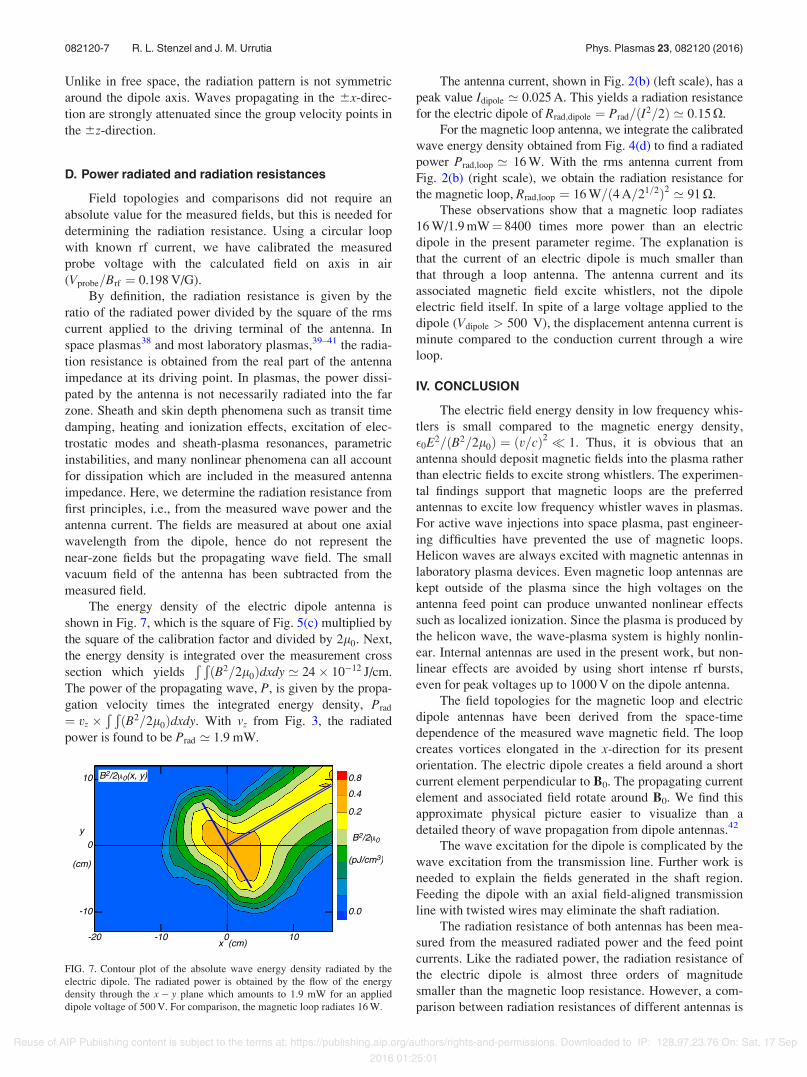
The energy density of the electric dipole antenna isshown in Fig. 7, which is the square of Fig. 5(c) multiplied bythe square of the calibration factor and divided by 2l0. Next,the energy density is integrated over the measurement crosssection which yields
Ð ÐðB2=2l0Þdxdy ’ 24& 10!12 J/cm.
The power of the propagating wave, P, is given by the propa-gation velocity times the integrated energy density, Prad
¼ vz &Ð ÐðB2=2l0Þdxdy. With vz from Fig. 3, the radiated
power is found to be Prad ’ 1.9 mW.
The antenna current, shown in Fig. 2(b) (left scale), has apeak value Idipole ’ 0.025 A. This yields a radiation resistancefor the electric dipole of Rrad;dipole ¼ Prad=ðI2=2Þ ’ 0:15 X.
For the magnetic loop antenna, we integrate the calibratedwave energy density obtained from Fig. 4(d) to find a radiatedpower Prad;loop ’ 16 W. With the rms antenna current fromFig. 2(b) (right scale), we obtain the radiation resistance forthe magnetic loop, Rrad;loop ¼ 16 W=ð4 A=21=2Þ2 ’ 91 X.
These observations show that a magnetic loop radiates16 W/1.9 mW¼ 8400 times more power than an electricdipole in the present parameter regime. The explanation isthat the current of an electric dipole is much smaller thanthat through a loop antenna. The antenna current and itsassociated magnetic field excite whistlers, not the dipoleelectric field itself. In spite of a large voltage applied to thedipole (Vdipole > 500 V), the displacement antenna current isminute compared to the conduction current through a wireloop.
IV. CONCLUSION
The electric field energy density in low frequency whis-tlers is small compared to the magnetic energy density,!0E2=ðB2=2l0Þ ¼ ðv=cÞ2 * 1. Thus, it is obvious that anantenna should deposit magnetic fields into the plasma ratherthan electric fields to excite strong whistlers. The experimen-tal findings support that magnetic loops are the preferredantennas to excite low frequency whistler waves in plasmas.For active wave injections into space plasma, past engineer-ing difficulties have prevented the use of magnetic loops.Helicon waves are always excited with magnetic antennas inlaboratory plasma devices. Even magnetic loop antennas arekept outside of the plasma since the high voltages on theantenna feed point can produce unwanted nonlinear effectssuch as localized ionization. Since the plasma is produced bythe helicon wave, the wave-plasma system is highly nonlin-ear. Internal antennas are used in the present work, but non-linear effects are avoided by using short intense rf bursts,even for peak voltages up to 1000 V on the dipole antenna.
The field topologies for the magnetic loop and electricdipole antennas have been derived from the space-timedependence of the measured wave magnetic field. The loopcreates vortices elongated in the x-direction for its presentorientation. The electric dipole creates a field around a shortcurrent element perpendicular to B0. The propagating currentelement and associated field rotate around B0. We find thisapproximate physical picture easier to visualize than adetailed theory of wave propagation from dipole antennas.42
The wave excitation for the dipole is complicated by thewave excitation from the transmission line. Further work isneeded to explain the fields generated in the shaft region.Feeding the dipole with an axial field-aligned transmissionline with twisted wires may eliminate the shaft radiation.
The radiation resistance of both antennas has been mea-sured from the measured radiated power and the feed pointcurrents. Like the radiated power, the radiation resistance ofthe electric dipole is almost three orders of magnitudesmaller than the magnetic loop resistance. However, a com-parison between radiation resistances of different antennas is
FIG. 7. Contour plot of the absolute wave energy density radiated by theelectric dipole. The radiated power is obtained by the flow of the energydensity through the x! y plane which amounts to 1.9 mW for an applieddipole voltage of 500 V. For comparison, the magnetic loop radiates 16 W.
082120-7 R. L. Stenzel and J. M. Urrutia Phys. Plasmas 23, 082120 (2016)
Reuse of AIP Publishing content is subject to the terms at: https://publishing.aip.org/authors/rights-and-permissions. Downloaded to IP: 128.97.23.76 On: Sat, 17 Sep
2016 01:25:01

only relevant if the antenna currents are comparable. This isnot the case for the present antennas. The electric dipole issuch a poor radiator compared to a loop antenna because ofthe low antenna current. Since a long linear wire can bedeployed on a spacecraft, two parallel wires should also bedeployable. By connecting the ends, an elongated magneticloop like ours would be formed and it radiates orders of mag-nitude more power than the single wire of an electricantenna. These findings should be very relevant to activeexperiments on whistler mode injection in space.
ACKNOWLEDGMENTS
The authors gratefully acknowledge support from NSF/DOE Grant No. 1414411.
1C. F. Kennel and H. E. Petschek, J. Geophys. Res. 71, 1, doi:10.1029/JZ071i001p00001 (1966).
2R. B. Horne, N. P. Meredith, R. M. Thorne, D. Heynderickx, R. H. A. Iles,and R. R. Anderson, J. Geophys. Res. 108, 1016, doi:10.1029/2001JA009165 (2003).
3M. M. Cowee, DITRIAC Dispatch 4, 2 (2014), available at www.dtra.mil/Research/DTRIAC/DTRIACDispatch.aspx.
4R. A. Helliwell, Rev. Geophys. 26, 551, doi:10.1029/RG026i003p00551(1988).
5U. S. Inan, T. F. Bell, J. Bortnik, and J. M. Albert, J. Geophys. Res. 108,1186, doi:10.1029/2002JA009580 (2003).
6P. Aigrain, in Proceedings of the International Conference onSemiconductor Physics, Prague, Publishing House of the CzechoslovakAcademy of Sciences, Prague, 1960 (Academic Press, New York andLondon, 1961), pp. 224–226.
7R. W. Boswell, Plasma Phys. Controlled Fusion 26, 1147 (1984).8C. R. Leg!endy, Phys. Rev. 135, A1713 (1964).9T. J. Dolan, Fusion Research (Pergamon Press, 2000), Vol. 1, p. 229.
10W. M. Stacey, Fusion: An Introduction to the Physics and Technology ofMagnetic Confinement Fusion, 2nd ed. (Wiley-VCH Verlag GmbH,Weinheim, Germany, 2010).
11R. Prater, C. Moeller, R. Pinsker, M. Porkolab, O. Meneghini, and V.Vdovin, Nucl. Fusion 54, 083024 (2014).
12R. L. Stenzel, Radio Sci. 11, 1045, doi:10.1029/RS011i012p01045 (1976).13W. Gekelman, J. Geophys. Res. 104, 14417, doi:10.1029/98JA00161 (1999).14A. V. Kostrov, M. E. Gushchin, S. V. Korobkov, and A. V. Strikovskii,
JETP Lett. 78, 538–541 (2003).15D. D. Blackwell, D. N. Walker, and W. E. Amatucci, Phys. Plasmas 17,
012901 (2010).
16R. K. Fisher and R. W. Gould, Phys. Rev. Lett. 22, 1093 (1969).17R. L. Stenzel, Phys. Fluids 19, 865 (1976).18H. Sugai, M. Maruyama, M. Sato, and S. Takeda, Phys. Fluids 21, 690
(1978).19T. Zaboronkova, A. Kostrov, A. Kudrin, S. Tikhonov, A. Tronin, and A. I.
Shaikin, Zh. Eksp. Teor. Fiz. 102, 1151 (1992), available at http://www.jetp.ac.ru/cgi-bin/e/index/e/75/4/p625?a=list.
20A. V. Kudrin, P. V. Bakharev, C. Krafft, and T. M. Zaboronkova, Phys.Plasmas 16, 063502 (2009).
21R. L. Stenzel, J. M. Urrutia, and K. D. Strohmaier, Phys. Plasmas 15,042307 (2008).
22R. L. Stenzel and J. M. Urrutia, Phys. Rev. Lett. 114, 205005 (2015).23T. F. Bell, U. S. Inan, and T. Chevalier, Radio Sci. 41, RS2009,
doi:10.1029/2005RS003260 (2006).24V. S. Sonwalkar, D. L. Carpenter, A. Reddy, R. Proddaturi, S. Hazra, K.
Mayank, and B. W. Reinisch, J. Geophys. Res. 116, A11210, doi:10.1029/2011JA016759 (2011).
25M. Scherbarth, D. Smith, A. Adler, J. Stuart, and G. Ginet, Proc. SPIE7438, 74380B-1–6 (2009).
26V. S. Sonwalkar, U. S. Inan, T. F. Bell, R. A. Helliwell, O. A. Molchanov,and J. L. Green, J. Geophys. Res. 99, 6173, doi:10.1029/93JA03310(1994).
27F. F. Chen, Plasma Sources Sci. Technol. 24, 014001 (2015).28J. M. Urrutia and R. L. Stenzel, Phys. Plasmas 21, 122107 (2014).29R. L. Stenzel and J. M. Urrutia, Phys. Plasmas 21, 122108 (2014).30C. L. Rousculp, R. L. Stenzel, and J. M. Urrutia, Phys. Plasmas 2, 4083
(1995).31R. L. Stenzel and J. M. Urrutia, Phys. Plasmas 22, 072110 (2015).32D. D. Blackwell, T. G. Madziwa, D. Arnush, and F. F. Chen, Phys. Rev.
Lett. 88, 145002 (2002).33R. L. Stenzel, J. M. Urrutia, and M. C. Griskey, Phys. Plasmas 6, 4450
(1999).34R. Gendrin, Planet. Space Sci. 5, 274 (1961).35R. A. Helliwell, Whistlers and Related Ionospheric Phenomena (Stanford
University Press, Stanford, CA, 1965).36R. L. Stenzel, J. M. Urrutia, and M. C. Griskey, Phys. Scr. T84, 112
(2000).37J. M. Urrutia and R. L. Stenzel, Phys. Plasmas 22, 092111 (2015).38M. Tsutsui, I. Nagano, H. Kojima, K. Hashimoto, H. Matsumoto, S.
Yagitani, and T. Okada, Radio Sci. 32, 1101, doi:10.1029/97RS00396(1997).
39S. Ohnuki, K. Sawaya, and S. Adachi, IEEE Trans. Antenna Propag. 34,1024 (1986).
40D. D. Blackwell, D. N. Walker, S. J. Messer, and W. E. Amatucci, Phys.Plasmas 14, 092106 (2007).
41P. Pribyl, W. Gekelman, and A. Gigliotti, Radio Sci. 45, RS4013,doi:10.1029/2009RS004266 (2010).
42D. Shaikh, J. Plasma Phys. 75, 117 (2009).
082120-8 R. L. Stenzel and J. M. Urrutia Phys. Plasmas 23, 082120 (2016)
Reuse of AIP Publishing content is subject to the terms at: https://publishing.aip.org/authors/rights-and-permissions. Downloaded to IP: 128.97.23.76 On: Sat, 17 Sep
2016 01:25:01