comparison of anterior denture teeth arrangements made
TRANSCRIPT

Marquette Universitye-Publications@Marquette
Master's Theses (2009 -) Dissertations, Theses, and Professional Projects
Comparison of Anterior Denture TeethArrangements Made with the Tooth MoldTemplate and Definitive Computer-Aided Design& Computer-Aided Manufacturing CompleteRemovable Dental ProsthesesJose Antonio SierraMarquette University
Recommended CitationSierra, Jose Antonio, "Comparison of Anterior Denture Teeth Arrangements Made with the Tooth Mold Template and DefinitiveComputer-Aided Design & Computer-Aided Manufacturing Complete Removable Dental Prostheses" (2017). Master's Theses (2009 -). 395.http://epublications.marquette.edu/theses_open/395

COMPARISON OF ANTERIOR DENTURE TEETH ARRANGEMENTS MADE
WITH THE TOOTH MOLD TEMPLATE AND DEFINITIVE COMPUTER-AIDED
DESIGN & COMPUTER-AIDED MANUFACTURING COMPLETE REMOVABLE
DENTAL PROSTHESES
By
Jose Antonio Sierra D.D.S
A Thesis submitted to the Faculty of the Graduate School, Marquette University, in
Partial Fulfillment of the Requirements for the Degree of Master of Science
Milwaukee, WI
May 2017
ABSTRACT
COMPARISON OF ANTERIOR DENTURE TEETH ARRANGEMENT MADE WITH
THE TOOTH MOLD TEMPLATE AND DEFINITIVE COMPUTER-AIDED DESIGN
& COMPUTER-AIDED MANUFACTURING COMPLETE REMOVABLE DENTAL
PROSTHESES
Jose A. Sierra D.D.S
Marquette University, 2017
Introduction: There is a dearth of information in the refereed literature regarding
esthetics of CAD/CAM complete removable dental prostheses (CRDPs). The purpose of
this study was to investigate and compare the anterior denture teeth arrangement made
with the medium-size anterior tooth mold template to CAD/CAM complete removable
dental prostheses fabricated with bonded denture teeth and milled teeth.
Material and methods: Poly-vinyl siloxane impression were made of an
edentulous maxillary model and selected for use as the patient template. The edentulous
model was mounted on a semi-adjustable articulator. Definitive impressions and jaw
relation records were made according to the manufacturer’s protocol. Digital mock-ups of
the denture tooth arrangement were received by the manufacturer and confirmed prior to
processing. Ten CRDPs were generated; subgroups of 5 units were made and divided into
2 groups. One-half of the CRDPs were made by bonding manufactured denture teeth onto
denture base milled from pre-polymerized PMMA pucks, while the other half were made
by milling denture teeth directly.
For comparison, a Canon 70D camera mounted on a tripod was used for
photographic documentation. All photos were taken during the same day. Reference
markers placed on the edentulous model were used to orient and measure photos using
Photoshop CS4. Data was collected in the X-plane and the Y-plane and compared with
the tooth mold template. Data were statistically analyzed by Mann-Whitney U and
Wilcoxon signed-rank tests (α=.05)
Results: No statistical difference was found when CAD/CAM CRDPs milled and
bonded were compared. The tooth mold template represented the position of the central
incisors on the milled teeth and bonded teeth CRDPs. The inter-canine distance was
found to be 5 mm narrower on the CRDPs than the tooth mold template. The canines on
the CRDPs were 1 to 2 mm incisal when compared to the tooth mold template.
Conclusions: Tooth arrangements in bonded and milled CAD/CAM CRDPs did
not accurately reproduce the tooth mold template’s measurements in terms of intercanine
distance and position. There was no significant difference between tooth position on the
milled and bonded CAD/CAM CRDPs

i
ACKNOWLEDGMENTS
Jose A. Sierra D.D.S.
I would also like to thank my family, specifically my wife Laura, and my parents
Jose Antonio and Martha Sierra for their patience as I undertook this endeavor. I would
like to acknowledge the members of my thesis committee without whom this thesis
would not be possible: Drs. Geoffrey Thompson, Georgios Maroulakos, Seok Hwan
Cho, and Carl Drago. Finally, I would like to thank Marquette University School of
Dentistry, as well as its faculty and administration.

ii
TABLE OF CONTENTS
ACKNOWLEDGMENTS …...………………………………………………………….. i
TABLE OF CONTENTS………………………………………………………………... ii
LIST OF TABLES. ……………………………………………………………...………iii
LIST OF FIGURES………………………………………………………………………iv
CHAPTER
I. INTRODUCTION ………………………………………….……………...…….1
II. REVIEW OF THE LITERATURE……………………………………………....3
III. MATERIALS AND METHODS…………………………………………...…...10
IV. RESULTS……………………………………………………………...………..19
V. DISCUSSION…………………………………………………………………...24
VI. CONCLUSION………………………………………………………………. ...32
VII. BIBLIOGRAPHY…………………………………………...…………....……. 33
VIII. APPENDIX A…………………………………………………..……………...47

iii
LIST OF TABLES
Table 1. Relative values analysis showing mean differences in millimeters measured from Tooth
Mold Template (interquartile range) for each group, milled and bonded …………………… 22
Table 2. Mann-Whitney U test analyzing differences in relative values between milled and
bonded …………………………………………………………………………….……………. 23
Table 3. Wilcoxon signed-rank test analyzing differences between milled and bonded relative
values to anterior tooth template …………………………………………….…......................... 23

iv
LIST OF FIGURES
Figure 1. Maxillary Edentulous Model …………………………………………………………. 12
Figure 2. Maxillary Record Base and Occlusal Rim ………………………………………......... 12
Figure 3. Mandibular Record Base and Occlusal Rim …………………………………….......... 12
Figure 4. Arbitrary Mounting Index with Wax Occlusal Rim and Model (Frontal view) …….... 13
Figure 5. Arbitrary Mounting Index with Wax Occlusal rim and Model (Sagittal view) ............ 13
Figure 6. AMD Record with Bite Registration Occlusal (Frontal view) ……………………….. 14
Figure 7. AMD Record with Tooth Mold Template …………………………………………….. 14
Figure 8. Maxillary Definitive Impression ……………………………………………………… 14
Figure 9. Mandibular Definitive Impression ……………………………………………………. 14
Figure 10. Digital Maxillary Intaglio Surface of CRDP …………………………………………. 15
Figure 11. Digital Maxillary Teeth Arrangement (Frontal view) ……………………………..… 15
Figure 12. Studio Set-up ……………………………………………………………………….... 16
Figure 13. Reference Lines for Measurements ………………………………………………….. 16
Figure 14. Photoshop Example of Tooth Mold Template Superimposed to CRDP Teeth
Arrangement …………………………………………………………………………………...... 17

1
CHAPTER 1
INTRODUCTION
The estimated prevalence of complete edentulism in 2020 will be 37.9 million
adults; a 10% decline in age specific population has also been reported.1 Though the rate
of edentulism continues to drop, the increase in population has created more need than
ever before.1,2 Yoshida et al. reported that oral health has an impact of the quality of life
(QOL) of the elderly (>65 years) and is significantly decreased in the edentulous elderly
population.3 In that study, several factors were analyzed such as eating, verbal
communication, physical comfort, loneliness, job and hobbies, meaningfulness (as it
pertains to their lives), social life, and economic problems.3 Other authors found patient
satisfaction was greatly correlated to the dental appearance.4-7 Furthermore, a pleasing
dental appearance has been related to a satisfying psychological comfort.7-10
Conventional fabrication of complete removable denture prostheses (CRDPs) has
been shown to be clinically predictable for almost a century.11 The conventional method
presents with some limitations: 1. number of patients visits, 2. high treatment costs due to
multiple visits, 3. Dental laboratory expense, 4. lack of intimate fit between the denture
base and the edentulous ridge due polymerization shrinkage, and 5. difficulty in
recreating a duplicate denture.12,13 While computer aided design/computer aided
manufacture (CAD/CAM) fabrication of CRDPs has its own limitations, there are several
advantages that CAD/CAM fabricated dentures have over the traditional method: 1.
reduced number of patient visits, 2. superior strength and fit of dentures due to use of
prepolymerized acrylic resin blocks for milling, 3. reduction microorganism adherence in

2
dentures, 4. reduced cost for the patients and dentists, and 5. duplication of the dentures
is easier and more accurate due to stored digital data.12-16 The key differences in
CAD/CAM fabrication of CRDPs when compared to conventional fabrication methods
include the lack of a trial arrangement appointment. One manufacturer specially
recommends that clinicians may go directly from the impression/records appointment to
insertion of the definitive prostheses.30
The purpose of this study was to investigate and compare linear measurements
associated with the anterior denture teeth arrangement made with the medium-size
anterior tooth mold template (Global Dental Science LLC, Scottsdale, AZ) to the
CAD/CAM complete removable dental prostheses (CRDPs) fabricated with bonded
denture teeth and CAD/CAM CRDPs milled teeth. The clinical implication of the study
was to provide dental professionals with clinical information about the accuracy and
precision of the medium-size anterior tooth mold template (Global Dental Science,
Scottsdale, AZ) with this specific CAD/CAM CRDP fabrication technology.

3
CHAPTER 2
REVIEW OF THE LITERATURE
Complete removable dental prosthesis has been a common dental procedure to treat
edentulous patients throughout history. The earliest appearance of maxillary and
mandibular CRDPs was approximately 1500 in Switzerland. These early CRDPs were
carved from an ox’s femur and tied together at the posterior phalanges to form a hinge.
These dentures were considered to be cosmetic rather than functional since the dentures
typically were fabricated directly over carious teeth.17 Modern dental prosthesis in more
modern times were introduced by Matthias Gottfried Purmann in his Wundarzenei of 1684,
as cited by Guerini.17 In 1839, Charles Goodyear created Vulcanite and later used the
material to create denture bases in 1855. During the same year, aluminum casting was
explored as a potential means of fabricating denture bases. In 1870, an aluminum casting
machine was created that allowed for denture bases to be made of aluminum in
combination with vulcanite and prosthetic teeth.17,19 Vulcanite was later replaced by acrylic
resin polymers, which were first introduced as denture base materials in 1937.17,18 In 1937,
Wright found that methyl methacrylate resin (Vernonite) met the requirements for an ideal
base material.18,19 Although methyl methacrylate resin is far from an ideal denture base
material it possesses superior properties when compared with Vulcanite. Some of the
concerns with Vulcanite denture bases had limitations associated with physical
characteristics such porosity, absorbency, opacity and lifeless appearance.17-19
Furthermore, vulcanite was difficult to fabricate, technique sensitive and provided lab
equipment complexity.17-19

4
Since its introduction, polymethyl methacrylate (PMMA) has been the most
commonly used resin employed to make removable dental prostheses.18,19 Conventional
denture processing with PMMA consists of investing/flasking dentures and master casts
with plaster/stone into flasks; boil out to soften and remove the wax the denture is covered
with plaster/stone and placed in boiling water for 5-10 minutes), elimination of the wax
from the resultant molds, packing the resin (packing the acrylic resin into the mold,
removing excess and re-packing), and curing the acrylic resin (polymerization of acrylic
resin in a water bath heated to approximately 162 degrees F where the flask is
submerged).20
Denture resin may be polymerized by using several different methods. Nishii was
the first to report on using microwave energy in 1968 to polymerize denture resins.15,21 The
discrepancies between processed denture bases and the stone casts were less when using
microwave energy was used for polymerization when compared with the hot water bath
method was used. However, no difference was noted between the microwave method (500
watts, 3 minutes) and the conventional hot water bath method when the standard protocol
(74o C, 8 hours) was followed. 22-24 Peyton found there was no difference in polymerization
shrinkage as long as the temperature wascontrolled.19
Digital technology was initially used in dentistry during the 1950s. In 1957, the
world’s first CAM software program, named PRONTO, was developed by Dr. Patrick J.
Hanratty. As a result, Hanratty is referred to as the father of CAD/CAM technology.15, 25
PRONTO became commercially available in the late 1960s. In the early 1980s, Andersson
introduced CAD/CAM technology for use with fabricating titanium crowns clinically.15
Andersson went on to develop the CAM portion of the fabrication process by combining

5
spark erosion and copy milling.15 In 1983, Procera (Nobel Biocare, Kloten, Switzerland)
was created for CAD fabrication processes. The first CAD/CAM Procera crown made from
a computer file instead of from a conventional stone die was made in 1990.15 In 1994,
Maeda et al were the first to report in English the use of computer-aided technology to
fabricate complete dentures.15,26 In 1997, a report by Kawahata et al investigated digital
duplication of existing dentures and milling them by use of a computerized numerical
control (CNC) machine which used a subtractive manufacturing method.15,27 Subtractive
manufacturing is milling a workpiece from a blank puck via CNC machine.40 The CAM
software translates the information to a CAD model where removal or subtraction of
material was performed via milling instruments. In 2008, Sun et al investigated 3D laser
scanning of edentulous casts, occlusion rims, digital tooth arrangements and created virtual
flasks for denture processing. The dentures were fabricated through rapid prototyping
technology, 3D printed or additive layer manufacturing, which created physical flasks and
dentures. Teeth were inserted onto the denture bases and conventional laboratory
procedures were used to fabricate complete dentures.15, 29 In 2012, Goodacre investigated
scanning silicone impressions, interocclusal records, and developed virtual tooth
arrangements. The denture bases were CNC milled from a block of acrylic resin followed
by manual bonding of denture teeth into precut openings in the bases.15,30 It has been
reported that pre-polymerized acrylic resin provided superior fit and strength compared to
conventionally processed acrylic resin denture bases.12 Since the pre-polymerized acrylic
resin was milled from previously processed resin, it was considered to be more accurate
and eliminated the need for a posterior palatal seal in maxillary complete dentures.31
Limitations with this fabrication process included obtaining optimal or accurate occlusal

6
vertical dimension (OVD) records, maxillomandibular relationship record (MMRR),
evaluating lip support without the benefit of maxillary occlusion rims, evaluating maxillary
incisal edge position, establishing mandibular occlusal plane, and obtaining patient input
and esthetic consent. Additionally, materials and laboratory costs were higher than
traditional methods.12, 32
Conventional CRDPs have been traditionally fabricated over five clinical
appointments.15 One appointment may be dedicated to each step, or several steps can be
combined during an appointment. The steps have been identified as follows: examination
and preliminary impressions, definitive impressions, maxillomandibular relationship
records, wax denture trial evaluations, and CRDP insertion.15 Even though the
conventional protocol was considered predictable and successful, 26 there are certain
disadvantages associated with it. Some of these disadvantages include:
1) the number of patient visits including post-insertion visits;
2) high treatment costs due to multiple patient visits; 3)
dental laboratory expenses; 4) lack of intimate fit between
denture bases and edentulous ridges due to polymerization
shrinkage; and 5) difficulty in creating duplicate dentures.
2) In addition to these disadvantages, several authors have
also noted 1) the increase in aging population and resultant
increased demand for CRDPs, 2) A shortage of dental
laboratory technicians in the US created greater difficulty
for clinicians in obtaining the services of competent
complete denture laboratory technicians.27,29,33

7
There are multiple advantages associated with CAD/CAM fabrication of CRDPs including:
1) the number of patient visits has been reported to be significantly
reduced16 2) superior strength and fit of dentures due to use of pre-
polymerized acrylic resin blocks for milling; 3) reduced potential for
CAD/CAM dentures to harbor micoorganisms12, 30 4) reduced costs for
patients and dentists; 5) replication of CADCAM dentures is easier due to
the fact that all of the data for fabricating the dentures have been digitized
and easily stored. .27, 29, 33
A significant difference between the CAD/CAM fabricated dentures and
conventional dentures is the fabrication process and use of PMMA. The conventional
denture curing method uses PMMA by mixing the polymer power and monomer into a
dough state and then placing the resin into a mold. The denture flask was submerged into
a water bath; the resin was cured 162oF for 8 hours.20 The CAD/CAM fabricated
complete dentures are made from a pre-polymerized PMMA, PMMA blocks with a
subtractive manufacturing process recesses that correspond to the location of the
treatment planned teeth are milled into the blocks of resin/denture bases; The
conventional method had reported volumetric shrinkage of 7-8% while the CAD/CAM
method reported no shrinkage in the PMMA pucks nor any values have been
reported.30,34
In contrast with conventional CRDPs, CAD/CAM CRDPs where clinicians have
multiple choices in selecting tooth molds for patients, CAD/CAM CRDPs use a medium-
size tooth mold template for the anterior denture teeth setup.16,30,33 The tooth mold

8
template is an outline of six anterior teeth on an sticker provided by the company to
establish midline, cementoenamel junction, intercanine distance and incisal edge
position.30 (Figure 7) This template tab may be used as an alternative to a traditional wax
denture try-in. After the clinical procedures for this CAD/CAM protocol, the denture
bases are CNC milled from a gingival colored blocks of acrylic resin. After the denture
bases have been milled, they are prepared for insertion of the denture teeth. The denture
teeth are then manually bonded into the precut openings on the bases. 30,35 Furthermore,
this medium-size tooth mold template may be used to make a monolithic milled CRDP
where tooth shapes and positions are taken from a digital library and milled into the
denture bases.35
However, few studies of CAD/CAM CRDPs have been reported, and fewer
studies have analyzed the accuracy of the tooth mold template used in this process.
According to this manufacturer (Global Dental Sciences, Scottsdale, AZ, USA),
clinicians prescribing this type of CAD/CAM CRDPs, use a tooth mold template in order
to record the midline, incisal edge positions, teeth size, and gingival heights of the
anterior teeth. Several authors have discussed that development of optimal esthetics is a
significant factor in CRDP success.5-11 Authors have often correlated patient’s psyche to
denture success.5-11 Since teeth are an important part of dental/facial esthetics, it is
important to evaluate the accuracy of this tooth mold template for proposed tooth setups.
This is a distinct limitation of this particular protocol whereby clinicians either have to
spend additional money for white try-in dentures (and an additional clinical appointment)
or proceed directly from the records appointment to insertion of the definitive dentures
without a wax try-in.

9
Following the review of the literature, it was determined that esthetics of
CAD/CAM CRDPs is an area without a lot of information, Hence, the null hypothesis for
this thesis is there will be no difference when comparing the position of the medium-size
anterior tooth template and bonded or milled denture teeth in the finished CRDP groups.

10
CHAPTER 3
MATERIALS AND METHODS
Data were acquired and a power analysis was performed in order to determine the
number of specimens required to complete this study. As a result of the power analysis, a
collection of 10 CRDPs were assembled and used as test specimens. The CRDPs were
fabricated per the protocol established by AvaDent (Global Dental Sciences, Scottsdale,
AZ).
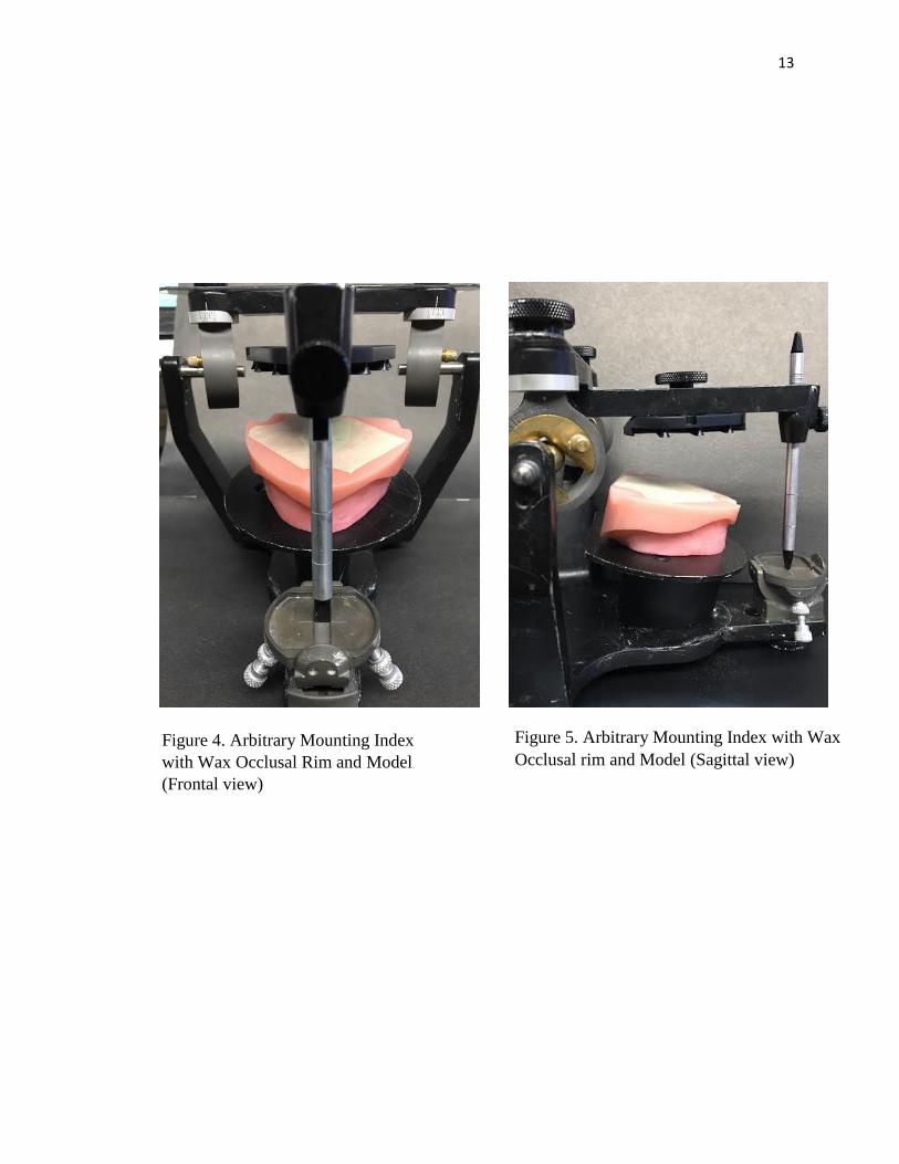
Two trial bases and occlusal rims were made on the maxillary and mandibular
models. Average lengths were used to identify the location of the occlusal aspects of the
occlusion rims: 22 mm for the maxillary cuspids; 18 mm for the mandibular
cuspids.20(Figure 2 and 3) The maxillary edentulous model and occlusal rim was placed
on a Hanau remounting record plate (Whip Mix, Louisville, KY). An arbitrary
maxillomandibular relation record was made and the mandibular model was mounted.
(Figure 4 and 5) Two custom trays were made on B-3 series maxillary and mandibular
edentulous models (Farasco, Greenville, NC) simulated patient template (Fig. 1). Border
molding of the edentulous models were made with polyvinyl siloxane (PVS) heavy body
impression material and a definitive impression made with a PVS light body wash
impression (AvaDent Impression Material, Global Dental Sciences, Scottsdale, AZ)
(Figures 8 and 9). Maxillary and mandibular Anatomic Measuring Devices (AMDs) were
used to record the OVD, MMRR, and assess the smile design. AvaDent Adhesive was
applied to the AMD, and border molding was completed by applying AvaDent Border
Molding material (AvaDent Impression Material, Global Dental Sciences, Scottsdale,
AZ) to the intaglio surface of the AMD, and positioning them onto the edentulous
11
models. The AMDs were completely seated onto the edentulous models, centered on the
edentulous model midline, and horizontally positioned parallel to the mandibular ridge.
(Figure 6) The occlusal vertical dimension was maintained with the central tracing pin set
to 40mm. A notch was made in the mandibular record base for the central tracing pin to
identify the arbitrary position regarding vertical dimension and centric jaw relationships.
The medium size tooth mold template sticker was attached to anterior plastic arch to
identify the maxillary dental midline and incisal edge position. (Figure 7) Additional
interocclusal registration material was flowed between the maxillary and mandibular
AMDs to interlock and record the maxillomandibular relationship. The impressions and
AMDs were shipped to AvaDent (Global Dental Sciences, Scottsdale, AZ) where they
were scanned by a Dental Wings scanner (Dental Wings Inc., Montreal, QC, CA). All of
the information in the impressions was digitized. The maxillomandibular relationships
and the proposed tooth locations were identified and made by the investigator. After all
of the scans were completed, a designer used a proprietary computer software to make a
tentative virtual tooth arrangement which was sent to the investigator via email for
evaluation. (Figure 10 and 11) The selection of the 22 E mold from Dentsply Portrait IPN
(Dentsply Sirona, York, PA) was made for use with the bonded teeth group. The
monolithic milled teeth were taken from a scanned 22 E tooth mold library (Global
Dental Science, Scottsdale, AZ) and milled from a PMMA tooth colored puck.

12
Figure 1. Maxillary Edentulous Model
Figure 2. Maxillary Record Base and
Occlusal Rim
Figure 3. Mandibular Record Base and
Occlusal Rim
13
Figure 4. Arbitrary Mounting Index
with Wax Occlusal Rim and Model
(Frontal view)
Figure 5. Arbitrary Mounting Index with Wax
Occlusal rim and Model (Sagittal view)

14
Figure 6. AMD Record with Bite
Registration Occlusal (Frontal view)
Figure 7. AMD Record with Tooth Mold
Template
Figure 8. Maxillary Definitive Impression Figure 9. Mandibular Definitive Impression

15
Figure 10. Digital Maxillary Intaglio Surface of CRDP
Figure 11. Digital Maxillary Teeth Arrangement (Frontal view)

16
Figure 12. Studio set-up
Figure 13. Reference Lines for Measurements. A. horizontal reference lines
associated with the Maxillary Incisal Edges. B. Inter-canine distance (Mid
Labial Lobe). C. Midline – X- axis. D. Midline – Y- axis E. Central Incisor
Length

17
All CRDP models were photographed in one day by one investigator. (Figure 12) All
CRDP models were measured digitally via Photoshop (Adobe Photoshop CS4, Adobe
Systems Incorporated, San Jose, CA) (Fig 14). Markers were placed on the edentulous
model for guidance in superimposition of photos. The CRDP models were prepared where
the anterior tooth mold templates were used to arrange the teeth digitally. A single
examiner conducted all measurements.
Ten linear dimensions were measured on each model in the computer in two planes (X
and Y) all measurements were recorded to the nearest 0.01 mm. The measurements were
made three times, and recorded. The average measurements were determined and used in
the data analysis. The following dimensions were selected for measurement:
Figure 14. Photoshop Example of a Milled Maxillary CRDP with a Tooth Mold
Template; the template was superimposed onto the CRDP. In this case, the anterior
teeth were monolithic milled.

18
X plane:
a. Inter-canine distance – the distance between maxillary canines at their
height of contour in the cervical third and compared between tooth mold
template and CRDP models (Figure 13, B).
b. Midline – The point between teeth 8 and 9 on the tooth mold template
midline and compared to CRDP models (Figure 13, C).
Y plane:
a. Midline – measured as the distance between the averages of the incisal
embrasures of cross marks on the tooth mold template to the reference point
of the edentulous model. (Figure 13, D).
b. Horizontal reference line – measured as the distance between the tooth
outlines of tooth mold template to incisal edge of milled teeth 6, 7, 8, 9, 10,
and 11. (Figure 13, A).
c. Central incisal length - measured as the distance between the tooth molds
template incisal edges to the greatest height of cervical outline of the
maxillary right or left central incisor. Tooth outline #1 was selected for use.
(Figure 13, E).
Data were statistically analyzed by Mann-Whitney U and Wilcoxon signed-rank
tests. Variable differences between the two tested groups were analyzed with the Mann-
Whitney U test. Variable differences between each group and the TMT were tested with
the Wilcoxon signed-rank test. All statistical analyses were completed using a statistical
package (SPSS Statistics version 23, IBM). The level of statistical significance (α) was set
at .05. Sample size was calculated to detect differences with 80% power and effect size
d=1.775 (G*Power 3.1.9.2; Erdfelder, Faul & Buchner).
19
CHAPTER 4
RESULTS
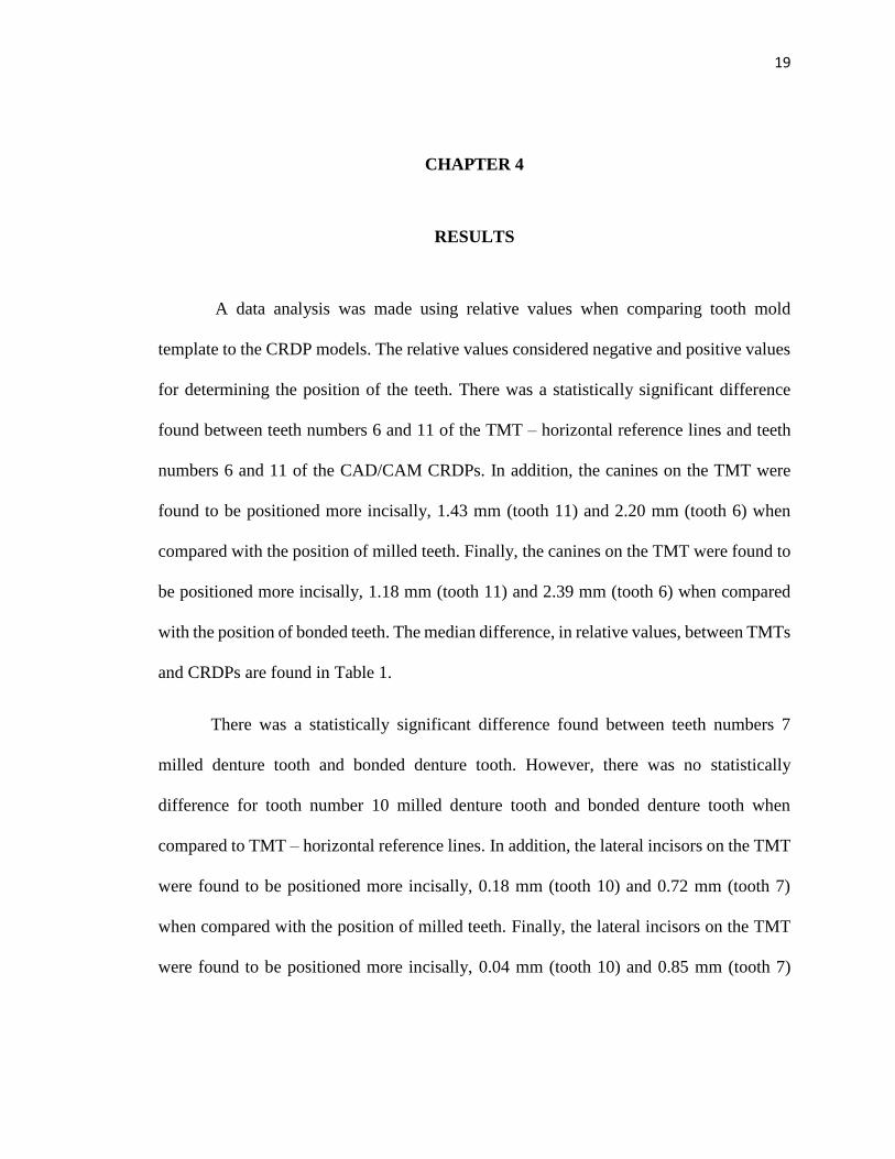
A data analysis was made using relative values when comparing tooth mold
template to the CRDP models. The relative values considered negative and positive values
for determining the position of the teeth. There was a statistically significant difference
found between teeth numbers 6 and 11 of the TMT – horizontal reference lines and teeth
numbers 6 and 11 of the CAD/CAM CRDPs. In addition, the canines on the TMT were
found to be positioned more incisally, 1.43 mm (tooth 11) and 2.20 mm (tooth 6) when
compared with the position of milled teeth. Finally, the canines on the TMT were found to
be positioned more incisally, 1.18 mm (tooth 11) and 2.39 mm (tooth 6) when compared
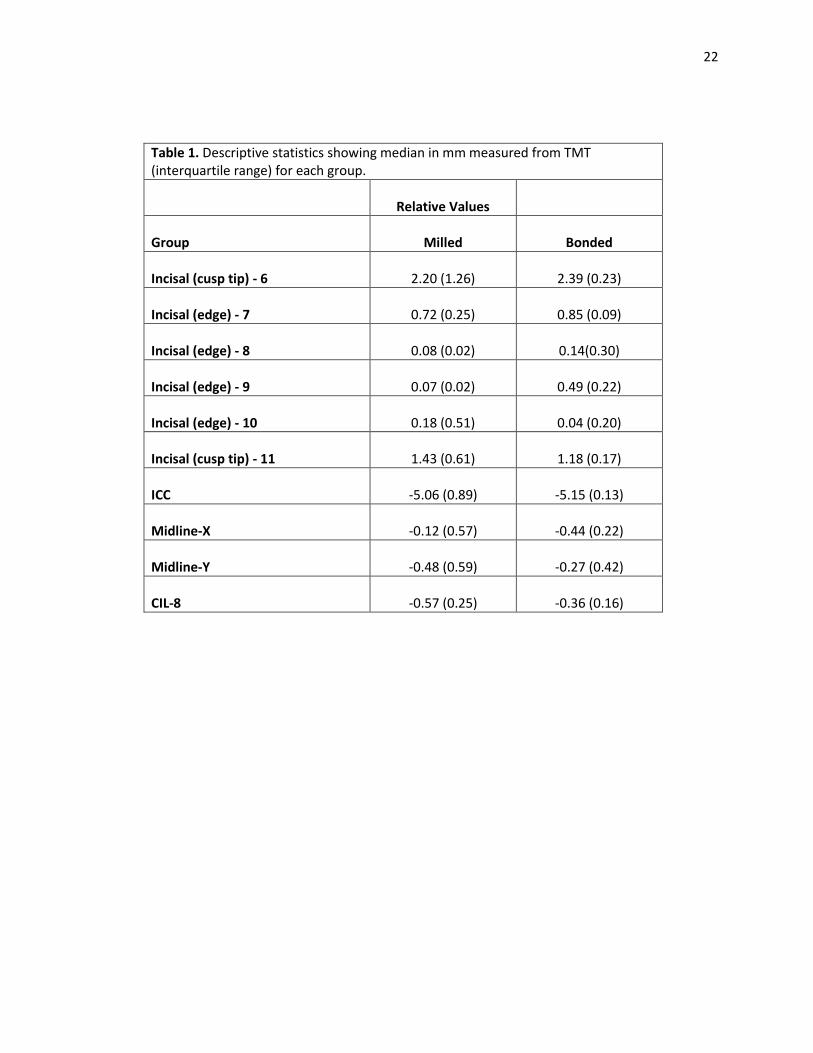
with the position of bonded teeth. The median difference, in relative values, between TMTs
and CRDPs are found in Table 1.
There was a statistically significant difference found between teeth numbers 7
milled denture tooth and bonded denture tooth. However, there was no statistically
difference for tooth number 10 milled denture tooth and bonded denture tooth when
compared to TMT – horizontal reference lines. In addition, the lateral incisors on the TMT
were found to be positioned more incisally, 0.18 mm (tooth 10) and 0.72 mm (tooth 7)
when compared with the position of milled teeth. Finally, the lateral incisors on the TMT
were found to be positioned more incisally, 0.04 mm (tooth 10) and 0.85 mm (tooth 7)

20
when compared with the position of bonded teeth. The median differences, in relative
values, between TMTs and CRDPs are found in Table 1.
There was a statistically significant difference found between teeth numbers 9
milled denture tooth and bonded denture tooth. There was statistically significant
difference found on tooth number 8 milled denture tooth. However, there was no
statistically difference for tooth number 8 bonded denture tooth when compared to TMT –
horizontal reference lines. In addition, the central incisors on the TMT were found to be
slightly positioned incisally 0.08 mm (tooth 8) and 0.07 mm (tooth 9) when compared with
the position of milled teeth. Finally, the central incisors on the TMT were found to be
positioned more incisally, 0.14 mm (tooth 8) and 0.49 mm (tooth 9) when compared with
the position of bonded teeth. The median differences, in relative values, between TMTs
and CRDPs are found in Table 1
The inter-canine distances (ICC) differed between TMT and the CAD/CAM
CRDP models. The CRDP milled denture teeth was 5.06 mm and for the bonded denture
teeth ICC distances was 5.15 mm. In both instances, the inter-canine distance was found to
be narrower than the TMT inter-canine distance (Table 1).
The milled denture teeth midline-X, distance between8 and 9, median analyzed to
0.12 mm positioned towards the left of the TMT midline. The bonded teeth midline-X,
distance between 8 and 9, median analyzed to 0.44 mm positioned towards the left of the
TMT midline (Table 1).
The milled denture teeth midline-Y, was 0.48 mm apical when compared to the
TMT midline-Y. The bonded teeth midline-Y, was 0.27 mm apical to the TMT midline-Y.

21
The median analyzed for the central incisor length was 0.36 mm (bonded denture
teeth) and 0.57 mm (milled denture teeth). There was no difference found between the sets
of central incisor lengths (Table 1).
When the CRDP–milled denture teeth and CRDP–bonded denture teeth were
compared, there was a statistical difference regarding the incisal position of tooth 9
(P<.008). Overall, the milled denture teeth and the bonded denture teeth CRDPs were
found to be accurate representations of one another (Table 3).
There were statistical differences when the TMT was compared to the milled and
bonded denture teeth groups. However, the incisal edge of tooth 10 and the midline - X
showed no statistical difference between the milled denture teeth group when compared to
the TMT. Furthermore, there were no statistical differences noted between the incisal edges
of teeth numbers 8 and 10 within the bonded denture teeth group. (Table 4)
22
Table 1. Descriptive statistics showing median in mm measured from TMT (interquartile range) for each group.
Relative Values
Group Milled Bonded
Incisal (cusp tip) - 6 2.20 (1.26) 2.39 (0.23)
Incisal (edge) - 7 0.72 (0.25) 0.85 (0.09)
Incisal (edge) - 8 0.08 (0.02) 0.14(0.30)
Incisal (edge) - 9 0.07 (0.02) 0.49 (0.22)
Incisal (edge) - 10 0.18 (0.51) 0.04 (0.20)
Incisal (cusp tip) - 11 1.43 (0.61) 1.18 (0.17)
ICC -5.06 (0.89) -5.15 (0.13)
Midline-X -0.12 (0.57) -0.44 (0.22)
Midline-Y -0.48 (0.59) -0.27 (0.42)
CIL-8 -0.57 (0.25) -0.36 (0.16)

23
Table 3. Relative Values
Mann-Whitney U Test
Difference between
Milled and Bonded
Incisal (cusp tip)- 6 .690
Incisal (edge) -7 .056
Incisal (edge)-8 .690
Incisal (edge)-9 .008*
Incisal (edge)-10 .310
Incisal (cusp tip) -11 .151
ICC .310
Midline-X .151
Midline-Y .222
CIL .056
*statistically significant difference (p <.05)
Table 2. Relative Values
Wilcoxon signed-rank Wilcoxon signed-rank
Difference between Difference between
Median and TMT Median and TMT
Milled Bonded
Incisal (cusp tip) - 6 .043* .043*
Incisal (edge) – 7 .043* .043*
Incisal (edge) - 8 .041* .109
Incisal (edge) - 9 .042* .043*
Incisal (edge) - 10 .223 .109
Incisal (cusp tip) - 11 .043* .043*
ICC .043* .043*
Midline-X .345 .043*
Midline-Y .043* .043*
CIL .043* .043*
*statistically significant difference (p <.05)

24
CHAPTER 5
DISCUSSION
After completing the experiment and the subsequent statistical analysis of the data,
it was determined that the null hypothesis could be rejected. The results of this study
indicate that a significant difference exists between the inter-canine widths and incisal
gingival positions of the teeth between the groups. However, when comparing the inter-
canine distances between the milled denture teeth group (5.06; p = 0.310) and the bonded
denture teeth group (5.15, p = 0.310) CRDPs were compared, there were no statistical
differences according to the Mann-Whitney U test. This suggests that CAD/CAM dentures
are accurate and reproducible within the study. (Table 2)
The results of this study corroborate the results of Kanazawa and Yamamoto who
found discrepancies in tooth position. Kanazawa and Yamamoto evaluated the fabrication
of a CRDP using a CAD/CAM system.36,37 Cone Beam Computed Tomography (CBCT)
was used to scan and measure the position of the denture teeth on the CRDPs. Kanzawa
mentioned the tendency to underestimate actual values of measurement were 94.4% with
a difference of less than 0.1.36 There was a tooth position deviation from the master 3D
data of approximately 0.10 mm for the polished buccal surface.36,37However, there was no
follow-up information regarding this measurement. The position of the occlusal surfaces
demonstrated less accuracy with maximum tooth position deviations that averaged t 0.88
mm and average deviations were reported to be 0.50 mm.36
Yamamoto analyzed CAD/CAM recesses whereby denture teeth were bonded by
resin cement (self-curing resin, UNIFAST III; GC, Tokyo, Japan) into the offset recesses

25
of 0.00 (control), 0.10, 0.15, 0.20, and 0.25 mm. The central incisor (CI), canine (C),
premolar (PM) and molar (M) denture teeth were bonded to each offset recesses. Offset
recesses were milled into the denture bases to provide additional space into the tooth
outline of the denture bases. The bonded denture teeth were scanned via CBCT and
digitally analyzed. The control group without offset recesses reported distance
measurements for the teeth as follows: CI to be 0.29 mm, C 0.25mm, PM 0.21mm, and M
0.15 mm with maximum deviations of 1.24 mm, 1.16 mm, 0.95 mm, and 0.62 mm
respectively. The increased offset recesses led to more accurate tooth position.37 Although
Yamamoto recognized dimensional change of the data caused by partial volume effect in
CBCT, there was no margin of error provided in the study.37
Dental professionals and patients can identify unpleasant dental aesthetics when
there are errors of 1.5-2 mm when evaluating crown lengths and 3–4 mm regarding crown
widths. By incorporating Kokich’s findings into this study, this may help in determining a
successful outcome in patient’s acceptance. 38
According to Goodacre, a comparison of the intaglio surface of CAD/CAM CRDPs
fit to the master casts was made from were found to be very accurate. (.002 - .017mm) In
Goodacre’s study, the casts and dentures were measured with laser scanners at the apex of
the denture border, 6mm from denture border, crest of ridge, palate and posterior palatal
seal. The following measurements were found: 0.017 mm, - 0.004 mm, 0.008 mm, -0.003
mm, and 0.002 mm respectively.31 He further stated that post palatal seals would not be
required in CAD/CAM CRDPs since, classically, post palatal seals were meant to offset
the 7-8% volumetric shrinkage associated with heat polymerized PMMA.34

26
The investigator in this study assumed that each denture would fit well on the
edentulous model. However, in order to complete seat the CRDPs onto the edentulous
model, it was necessary to make minor adjustments on the alveolar ridge of the edentulous
model to allow fitting of the CAD/CAM CRDPs due to their accuracy. Fit checker (vinyl
polyether silicone, GC America, Alsip, IL) was applied to the intaglio of each surface
CRDP, firmly pressed by hand onto the edentulous model. Incomplete seating was
identified with the fit checker and the alveolar ridges were adjusted as needed. Complete
seating of the CRDPs onto the edentulous models was confirmed visually at the depths of
the vestibules and hard palate. Accuracy of the fit checker was noted to be 0.1mm with a
Boley gauge.
Hanau’s hypothesis of “resilient and like effect” described tissue adaptation
potentially how volumetric shrinkage could induce a change in occlusal relationships and
post-operative adjustments39 The study, the soft tissue on the edentulous model is rigid,
according to the manufacturer, no volumetric shrinkage occurred since the CRDPs were
made of pre-polymerized PMMA and milled with a 10 µm accuracy.40
CAD/CAM fabrication processes may be classified as hard machining or soft
machining methods depending on the materials milled. Hard machining has been used for
metal, dense sintered zirconia and composite resin while the soft machining has been used
with pre-sintered zirconia. Hard machining requires strong cutting forces and power to
remove material efficiently. The cutting power conducts thermal energy and raises the
temperature of the milling instrument; this generally reduces the effectiveness and
longevity of the burs.40 It has also been noted that there was potential for error CAD/CAM

27
machining milling instrument fatigue resulting in imprecise cutting dimensions of teeth or
space in the acrylic resin dentures for future tooth placement.36
Another potential source of error in the current study was the volumetric shrinkage
of the impression materials and prior to digital scans.30 The reduction in volume has been
noted to be due to the polymerization process or handling with latex gloves containing zinc
diethyl dithiocarbamate. The zinc compound has been described as being an accelerator
for latex, by reacting to the platinum catalyst in the polyvinyl siloxane. This would delay
or total inhibition of polymerization of polyvinyl siloxane as low as 0.1 – 0.05%.20, 41
Furthermore, lower viscosity materials such as light bodied polyvinyl siloxane showed
greatest change (0.02-.05%) due to lower filler content.20, 41
The pre-polymerized condensed state of PMMA fabrication process used in this
specific CAD/CAM protocol to mill CRDPs has less porosity in when compared to
conventionally manufactured methods.14,3014 Porosity within denture bases has been
attributed to the boiling point of the PMMA monomer (100.8o C or 213.4o F) which is
higher than water. If the temperature during polymerization rises above the boiling point
of the residual monomer, then production of bubbles occurs. Porosity may occur in the
thickest portion of the denture.42 Furthermore, residual monomer is considered to be
hydrophilic and a fast diffuser, movement of molecules from a region of high concentration
to low concentration, that may cause tissue irritation, hypersensitivity, or allergic
reactions.20 However, if the CRDPs are boiled in a flask at 100o C for at least 1 hour, the
monomer content decreases to 0.2– 0.5 % which is considered clinically acceptable. 20
CAD/CAM milled acrylic resin has less residual monomer remaining after
processing and is more hydrophobic than the conventional acrylic resins. This may be the

28
reason why CAD/CAM processed denture bases are more hygienic and more suitable for
the patients. The State University of New York at Buffalo compared between CAD/CAM
acrylic resin, Lucitone 199 (Dentsply Sirona, York, PA, USA) and Diamond D (Keystone
Industries, Gibbstown, NJ, USA) where the acrylic resin discs were submerged in human
saliva at 37o C for 30 minutes. Subsequently, C. albicans was incubated on the dentures
discs for 1 hour and maintained at 37o C. The specimens are washed in sterile phosphate-
buffered saline, physiologic pH ~7.4, by dipping them 10 times in the solution. The adhered
cells that remained on the sample surface were evaluated using a microscope and
determined the number of cells per area unit. The authors reported that conventional
dentures retained 5-8% C. albicans while CAD/CAM retained 2%.30
Adherence of denture teeth onto milled PMMA resin originated from conventional
denture processing methods. One of the methods used by the manufacturer of the
CAD/CAM dentures used in this study was to mill solid pre-polymerized PMMA pucks
with recesses that corresponded to the planned positions of the denture teeth and use a
bonding agent to attach the teeth into the recesses milled into the denture bases. This
method has multiple limitations associated with it including routinely used since
methacrylate resin teeth may detach due to various factors such as: inadequate chemical or
mechanical preparation of the tooth surfaces, presence of porosities at the base-tooth
interface, impurities, processing inconsistencies, and water sorption of the resin and
differences in their coefficient of thermal expansions.20 Some considerations to prevent
debonding of denture teeth from denture bases included the use of mechanical and/or
chemical modifications to the acrylic resin material. The use of sandblasting and/or
making diatoric holes in the cervical surface area has been shown to increase

29
micromechanical retention between the denture teeth and denture base.20 The use of
chemical bonding with 4-META (4-methacryloxyethyl trimellitic anhydride) promoted
bonding of highly cross-linked methacrylate teeth to resin bases.20 Another method for
bonding resin teeth to chemically active denture resin includes softening the necks of
artificial denture teeth with a mixture of methylene chloride and methyl methacrylate
monomer for 5 minutes.20 The recesses of the denture bases per this manufacturer’s
protocol were milled for precise fitting of the denture teeth into the recesses. If chemical
bonding has been performed, adjustments to the necks of the teeth would be necessary to
provide space for the chemical bonding agent.37 This would possibly lead to tooth
displacement when bonded teeth were evaluated.37 The milled teeth have been designed
from a library of scanned teeth, milled, and within a PMMA puck that contains tooth and
pink color PMMA combined. Furthermore, the position of teeth for CAD/CAM milled and
bonded denture teeth in this study were not significantly different when compared to one
another and in some measures to the tooth mold template.
Saponaro clinically evaluated clinical use of conventional fabricated CRDPs and
CAD/CAM fabricated CRDPs in patients and noted several types of complications. The
following clinical complications were noted: lack of retention (8 of 48 patients), occlusal
vertical dimension discrepancy (4 of 48 patient), incorrect centric relationship (3 of 48
patients), poor esthetic outcome (3 of 48 patients), post-insertion adjustments visits (16 of
48 required 1 post-insertion visit; 14 of 48 required 2 visits; and 14 of 48 required 3 or
more visits), and remake of CAD/CAM CRDPs (5 of 48 participants). Saponaro reported
the remake of the CRDPs into conventional methods were due to maxillary midline
deviated, excessive gingival display and an allergic reaction to the dentures.43 Saponaro

30
reported the mean number of appointments to deliver CAD/CAM fabricated CRDPs was
2.38 and the number of post-insertion appointments was 2.12.43 Drago reported the results
of a clinical study where post-insertion visits in CRDPs were compared based on the type
of impression materials used in making the definitive impressions for CRDPs. One method
consisted of a traditional technique (custom impression trays border molded with gray
modeling plastic impression); the second method consisted of modifying the impression
protocol that included (custom impression trays border molded with heavy-body vinyl
polysiloxane impression material). The definitive wash impressions were made with light-
body vinyl polysiloxane impression material. The study found there was no significant
difference between the two techniques regarding the average number of adjustment visits
with each technique is 2.68.44 Bidra reported 3.3 denture adjustments visits with
CAD/CAM CRDPs.32
Some of the imitations associated with the current study are that a Z-plane (anterior
to posterior) evaluations was not performed. This was made difficult because it was
problematic when trying to establish a consistent Z plane reference point for all CRDPs.
Finally, it is difficult to extrapolate the outcomes of a laboratory study to the clinical
situation.
Future research is indicated that would analyze changes associated in the occlusal
relationships in CRDPs fabricated with the AvaDent protocol. Comparison of the accuracy
of maxillomandibular relationship records made using AvaDent’s guidelines compared
with traditional methods should also be evaluated. Lastly, the evaluation of physical
properties of AvaDent CRDPs compared to conventional heat-processed dentures should
also be studied in the laboratory, as well as, in patients.

31
CHAPTER 6
CONCLUSIONS
From this study, the following conclusions can be made:
1. The tooth mold template effectively represented the position of the central
incisors onto the CRDPs with milled denture teeth and CRDPs with bonded
denture teeth.
2. Inter-canine distances were found to be 5 mm narrower on both types of CRDPs
than with the tooth mold template. This may be clinically significant.
3. The canine positions of 6 and 11 were found to be 1 to 2 mm incisally positioned
on both CRDPs than the tooth mold template indicated. This may be clinically
significant.
4. Even though statistical differences were found, there was no clinical significant
differences noted when comparing CAD/CAM CRDPs with milled teeth and
CAD/CAM CRDP with bonded denture teeth.

32
BIBLIOGRAPHY
1. Douglass CW, Shih A, Ostry L. Will there be a need for complete dentures in the
United States in 2020? J Prosthet Dent 2002; 87: 5-8.
2. Carlsson G, Omar R. The future of complete dentures in oral rehabilitation. A
critical review. J of Oral Rehabilitation. 2010; 37: 143-156.
3. Yoshida M, Sato Y, Akagawa Y, Hiasa K. Correlation between quality of life and
denture satisfaction in elderly complete denture wearers. Int J Prosthodont 2001;
14: 77-80.
4. Weinstein M, Schuchman J, Lieberman J, Rosen Paul. Age and denture
experience as determinants in patient denture satisfaction. J Prosthet Dent 1988;
59: 327-329.
5. Davis LG, Ashworth PD, Spriggs LS. Psychological effects of aesthetic dental
treatment. J Dent 1998 Sep (26): 547-54.
6. Hirsh B, Levin B, Tiber N. Effects of patient involvement and esthetic preference
on denture acceptance. J Prosthet Dent 1972; 28: 127-132.
7. Vallittu PK, Vallittu ASJ, Lassila VP. Dental aesthetics – a survey of attitudes in
different groups of patients. J Dent 1996; 24: 335-338.
8. Vig RG. The denture look. J Prosthet Dent 1961. 9-15.
9. Lefer L, Pleasure MA, Rosenthal L. A psychiatric approach to the denture patient.
J Psychosom Res 1962 (6): 199-207.
10. Carlsson GE, Otterland A, Wenstrom A, Odont D. Patient factors in appreciation
of complete dentures. J Prosthet Dent 1967; 17: 322-8
11. Jacob RF. The traditional therapeutic paradigm: complete denture therapy. J
Prosthet Dent 1998; 79: 6-13.
12. Bidra AS., Taylor T., Agar JR. Computer-aided technology for fabricating
complete dentures: Systematic Review of historical background, current status
and future perspectives. J Prosthet Dent 2013; 109:361-366
13. Hirsh B, Levin B, Tiber N. Effects of patient involvement and esthetic preference
on denture acceptance. J Prosthet Dent 1972; 28: 127-132.

33
14. Baba NZ, Goodacre CJ, Kattadiyil MT. (2015) CAD/CAM Removable
Prosthodontics, in Clinical Applications of Digital Dental Technology (eds R
Masri and CF Driscoll), John Wiley & Sons, Inc, Chichester, UK, pages 107-138.
15. Goodacre CJ, Garbacea A, Naylor WP, Daher T, Marchack CB, Lowry J.
CAD/CAM fabricated complete dentures: concepts and clinical methods of
obtaining required morphological data. J Prosthet Dent. 2012; 107: 34-46.
16. Kattadiyil, MT, Goodacre CJ, Baba NZ. CAD/CAM complete dentures: a review
of two commercial fabrication systems. J Calif Dent Assoc 2013;41:407-16.
17. Murray MD, Darvell BW. The evolution of the complete denture base. Aust Dent
Journal 1993; 38: 216-9.
18. Sweeney WT. Denture base materials acrylic resins. J Am Dent Assoc 1939; 26:
1863-73.
19. Peyton FA. History of resins in dentistry. Dent Clin North Am 1975; 19: 211-22
20. Zarb GA, et. al. Prosthodontic treatment for edentulous patients. 13th ed. St.
Louis: Mosby, 2013. Chapter 10, pages 210.
21. Nishii M. Curing of denture base resins with microwave irradiation: with
particular reference to heat-curing resins. J Osaka Dent Univ. 1968; 2(1): 23-40
22. Wallace PW, Grasser GN. Myers ML, Proskin HM. Dimensional accuracy of
denture resin cured by microwave energy. J Prosthet Dent 1991 (66): 403-9.
23. Sanders JL, Levin B, Reitz PV. Comparison of the adaptation of acrylic resin
cured by microwave energy and conventional water bath. Quintessence Int 1991;
22: 181-186.
24. Huggett R, Brooks SC, Bates JF. The effect of different curing cycles on the
dimensional accuracy of acrylic resin denture base materials. Quintessence Dent
Technol 1984; 8: 365-71.
25. CAD software history. Internet. CADAZZ.com 2004. Available from
http://www.cadazz.com/cad-software-history.htm
26. Maeda Y, Minoura M, Tsutsumi S, Okada M, & Nokubi T. A CAD/CAM system
for removable denture. Part I: Fabrication of complete dentures. Int J Prosthodont
1994; 7: 17-21.
27. Kawahata N, Ono H, Nishi Y, Hamano T, Nagaoka E. Trial of duplication
procedure for complete dentures by CAD/CAM. J Oral Rehabil 1997; 24: 540-8.

34
28. Busch M, Kordass B. Concept and development of a computerized positioning of
prosthetic teeth for complete dentures. Int J Comput Dent 2006; 9: 113-20.
29. Sun Y, Lu P, Wang Y. Study on CAD & RP for removable complete denture.
Comp Methods Programs Biomed 2009; 93:266-72.
30. AvaDent Digital Dentures; Global Dental Science LLC. Available at
http://www.avadent.com
31. Goodacre, BJ, Goodacre CJ, Baba NZ, Kattadiyil MT. Comparing of denture
base adaptation between CAD/CAM and conventional fabrcication techniques. J
Prosthet Dent 2016; 116: 249-56.
32. Bidra AS, Farrell D, Burnham A, Dhingra A, Taylor TD, Kuo C. Prospective
cohort pilot study of 2-visit CAD-CAM monolithic complete dentures and
implant-retained overdentures: Clinical and patient-centered outcomes. J Prosthet
Dent 2016; 115: 578-586.
33. Kattadiyil, MT, Goodacre CJ, Baba NZ. CAD/CAM complete dentures: a review
of two commercial fabrication systems. J Calif Dent Assoc 2013;41:407-16.
34. Phoenix RD: Denture base resins. In Anusavice KJ, editor: Phillips’ science of
dental materials, ed 11, St Louis, 2003, WB Saunders, pp 721-757.
35. R. Kreyer. Personal communication. November 2016.
36. Kanazawa M, Inokoshi M, Minakuchi S, & Ohbayashi N. Trial of a CAD/CAM
system for fabricating complete dentures. Dent Mater J 2011; 30: 93-6.
37. Yamamoto S, Kanazawa M, Ivaki M, Jokanov, A, Minakuchi S. Effects of offset
values for artificial teeth positions in CAD/CAM complete denture. Comput Biol
Med. 2014 Sep; 52:1-7.
38. Kokich V, Kiyak H, Shapiro P. Comparing the perception of dentists and lay
people to altered dental esthetics. J Esthet Dent 1999; 11: 311-24.
39. Hanau, RL. Occlusal changes in centric relation. JADA. Oct. 1929
40. Abduo, J, Lyons K, Bennamoun M. Trends in Computer-Aided Manufacturing in
Prosthodontics: A Review of the Available Streams. Int J Dent 2014; 1-15.
41. Mandikos MN. Polyvinyl siloxane impression materials: an update on clinical
use. Aust Dent J 1998; 43: 438-434.
35
42. Phillips. Skinner E. Skinner’s Science of Dental Materials. 8th ed. W.B. Saunders,
1991, p. 189.
43. Saponaro, P. (2016). Clinical Performance of CAD/CAM fabricated complete
dentures: A retrospective study and assessment of patient satisfaction. (Electronic
Thesis or Dissertation). Retrieved from https://etd.ohiolink.edu/
44. Drago CJ. A retrospective comparison of two definitive impression techniques
and their associated postinsertion adjustments in complete denture prosthodontics.
J Prosthondont 2003; 12:192-197.
45. Fit Checker Advanced; GC America. Available at http://www.gcamerica.com
46. Academy of Prosthodontics. (2005). The glossary of prosthodontic terms. J
Prosth, 94(1), 10-92.

36
CHAPTER 7
APPENDIX A
Incisal Cusp tip 6
Incisal Edge 7
Incisal Edge 8
Incisal Edge 9
Incisal Edge 10
Incisal Cusp tip 11 ICC
Midline X
Midline Y
CI Length
3.3 0.85 0.09 0.08 0.46 1.69 -3.66 -0.12 -0.12 -0.35 3.09 0.57 0.09 0.09 0.18 1.43 -5.1 0.02 -0.36 -0.66 1.86 0.58 0.06 0.06 0.18 1.41 -4.95 -0.32 -0.76 -0.57
2 0.72 0.08 0.06 0.41 1.65 -5.06 0.13 -0.48 -0.72 2.2 0.79 0.08 0.07 -0.33 0.72 -5.3 -0.66 -0.89 -0.52
2.29 0.86 0.3 0.53 0.04 0.98 -5.04 -0.32 -0.46 -0.46 2.48 0.83 0 0.37 0.15 1.18 -5.22 -0.36 -0.27 -0.31 2.61 0.95 0.14 0.49 0 1.19 -5.13 -0.44 -0.12 -0.36 2.34 0.85 0 0.38 0 1.14 -5.15 -0.46 -0.01 -0.32 2.39 0.79 0.29 0.66 0.25 1.26 -5.21 -0.62 -0.51 -0.49

37
all measurements in millimeters (mm) Tooth Mold Template Milled 1 Milled 2 Milled 3 Milled 4 Milled 5
Midline - Y axis (between 8 and 9)
sample 1 22.88 22.78 21.94 22.1 22.42 22.01
sample 2 22.9 22.76 21.89 22.2 22.35 21.98
sample 3 22.89 22.77 21.92 22.1 22.45 22.02
Average 22.89 22.77 21.91667 22.13333 22.40667 22.00333
Midline - X axis (distance from midpoint to 8)
sample 1 -0.2 0.08 0.23 -0.12 0.31 -0.46
sample 2 -0.18 0.07 0.22 -0.13 0.33 -0.45
sample 3 -0.22 0.08 0.21 -0.12 0.34 -0.47
Average -0.2 0.076667 0.22 -0.12333 0.326667 -0.46
Canine to Canine
sample 1 43.64 39.96 38.55 38.67 38.53 38.26
sample 2 43.6 39.99 38.5 38.65 38.59 38.4
sample 3 43.62 39.92 38.51 38.68 38.56 38.3
Average 43.62 39.95667 38.52 38.66667 38.56 38.32
Inciso-cervical length for Max CI (8)
sample 1 10.46 9.99 9.79 9.87 9.71 10
sample 2 10.43 10.2 9.8 9.85 9.75 9.87
sample 3 10.45 10.1 9.78 9.9 9.73 9.9
Average 10.44666667 10.09667 9.79 9.873333 9.73 9.923333
Inciso-cervical length for Max CI (9)
sample 1 10.59 9.94 9.94 9.92 9.95 9.64
sample 2 10.58 9.91 9.93 9.83 9.93 9.68
sample 3 10.58 9.93 9.98 9.87 9.91 9.7
Average 10.58333333 9.926667 9.95 9.873333 9.93 9.673333
Incisal edge length from hor ref line (6)
sample 1 0 3.4 3.09 1.86 1.99 2.21
sample 2 0 3.2 3.089 1.87 2.01 2.19
sample 3 0 3.3 3.1 1.85 1.99 2.19
Average 0 3.3 3.093 1.86 1.996667 2.196667
Incisal edge length from hor ref line (7)
sample 1 0 0.87 0.56 0.58 0.72 0.78
sample 2 0 0.82 0.57 0.6 0.71 0.79
sample 3 0 0.85 0.58 0.57 0.73 0.79
Average 0 0.846667 0.57 0.583333 0.72 0.786667
Incisal edge length from hor ref line (8)
sample 1 0 0.08 0.1 0.05 0.08 0.08
sample 2 0 0.1 0.09 0.059 0.076 0.076
sample 3 0 0.1 0.089 0.06 0.078 0.078
Average 0 0.093333 0.093 0.056333 0.078 0.078
Incisal edge length from hor ref line (9)
sample 1 0 0.08 0.1 0.06 0.06 0.07
sample 2 0 0.078 0.092 0.059 0.068 0.073
sample 3 0 0.079 0.08 0.06 0.065 0.068
Average 0 0.079 0.090667 0.059667 0.064333 0.070333
Incisal edge length from hor ref line (10)
sample 1 0 0.45 0.17 0.175 0.41 -0.33
sample 2 0 0.46 0.18 0.176 0.42 -0.34
sample 3 0 0.46 0.176 0.174 0.4 -0.33
Average 0 0.456667 0.175333 0.175 0.41 -0.33333
Incisal edge length from hor ref line (11)
sample 1 0 1.688 1.4 1.39 1.64 0.72
sample 2 0 1.7 1.45 1.42 1.65 0.73
sample 3 0 1.69 1.43 1.41 1.66 0.71
Average 0 1.692667 1.426667 1.406667 1.65 0.72

38
all measurements in millimeters (mm) Tooth Mold Template Bonded 1 Bonded 2 Bonded 3 Bonded 4 Bonded 5
Midline - Y axis (between 8 and 9)
sample 1 22.88 22.46 22.63 22.77 22.94 22.38
sample 2 22.9 22.4 22.61 22.78 22.84 22.4
sample 3 22.89 22.43 22.615 22.76 22.85 22.36
Average 22.89 22.43 22.61833 22.77 22.87667 22.38
Midline - X axis (distance from midpoint to 8)
sample 1 -0.2 -0.12 -0.15 -0.23 -0.26 -0.41
sample 2 -0.18 -0.13 -0.16 -0.25 -0.25 -0.43
sample 3 -0.22 -0.12 -0.16 -0.25 -0.28 -0.42
Average -0.2 -0.12333 -0.15667 -0.24333 -0.26333 -0.42
Canine to Canine
sample 1 43.64 38.51 38.3 38.47 38.44 38.39
sample 2 43.6 38.65 38.5 38.5 38.5 38.4
sample 3 43.62 38.59 38.4 38.5 38.48 38.45
Average 43.62 38.58333 38.4 38.49 38.47333 38.41333
Inciso-cervical length for Max CI (8)
sample 1 10.46 9.99 10.1 10.07 10.12 9.95
sample 2 10.43 9.98 10.2 10.1 10.14 9.97
sample 3 10.45 9.98 10.1 10.1 10.11 9.96
Average 10.44666667 9.983333 10.13333 10.09 10.12333 9.96
Inciso-cervical length for Max CI (9)
sample 1 10.59 10.14 10.1 10.06 10.11 9.9
sample 2 10.58 10.1 10.2 10.2 10.13 9.93
sample 3 10.58 10.2 10.2 10.3 10.12 9.94
Average 10.58333333 10.14667 10.16667 10.18667 10.12 9.923333
Incisal edge length from hor ref line (6)
sample 1 0 2.3 2.5 2.64 2.32 2.41
sample 2 0 2.28 2.45 2.58 2.36 2.39
sample 3 0 2.3 2.48 2.6 2.35 2.38
Average 0 2.293333 2.476667 2.606667 2.343333 2.393333
Incisal edge length from hor ref line (7)
sample 1 0 0.87 0.82 0.96 0.83 0.79
sample 2 0 0.85 0.83 0.94 0.85 0.78
sample 3 0 0.85 0.83 0.95 0.86 0.8
Average 0 0.856667 0.826667 0.95 0.846667 0.79
Incisal edge length from hor ref line (8)
sample 1 0 0.29 0 0.12 0 0.3
sample 2 0 0.31 0 0.14 0 0.28
sample 3 0 0.29 0 0.15 0 0.3
Average 0 0.296667 0 0.136667 0 0.293333
Incisal edge length from hor ref line (9)
sample 1 0 0.39 0.37 0.49 0.41 0.66
sample 2 0 0.6 0.36 0.5 0.35 0.65
sample 3 0 0.59 0.37 0.48 0.38 0.67
Average 0 0.526667 0.366667 0.49 0.38 0.66
Incisal edge length from hor ref line (10)
sample 1 0 0.04 0.145 0 0 0.25
sample 2 0 0.03 0.146 0 0 0.26
sample 3 0 0.04 0.145 0 0 0.24
Average 0 0.036667 0.145333 0 0 0.25
Incisal edge length from hor ref line (11)
sample 1 0 1.015 1.16 1.19 1.16 1.24
sample 2 0 0.98 1.2 1.2 1.14 1.28
sample 3 0 0.95 1.18 1.18 1.12 1.26
Average 0 0.981667 1.18 1.19 1.14 1.26

39
Disclaimer
The authors received no financial support from the company for the completion of this
project and the publication of this research study.