comparativeanalysis of european and american … · elektronika ir...
TRANSCRIPT

ELEKTRONIKA IR ELEKTROTECHNIKA, ISSN 1392-1215, VOL. 22, NO. 2, 2016
1Abstract—Continuous work of mine supplying electricalpower networks is a prerequisite to ensure the continuity of themining process and the safety of its crew. The choice of theappropriate method for calculating short-circuit currents istherefore particularly important in terms of both economic andsafety considerations. The methods used are always acompromise between the accuracy of obtained results,computational complexity and availability of data necessary forcalculations. The study compares the two most commonstandards for calculating maximum short-circuit currents - IECand ANSI/IEEE. The study presents the most importantinterrelationships that describe the characteristic magnitudes ofshort-circuit currents for IEC standard and for the ANSI/IEEEstandard. This comparison has been done on the basis of novelcalculations performed on a typical MV mine network. Theresults of the calculations showed a high contiguity of theresults despite the different methodological assumptions forrotating machines modelling and for determining the equivalentvalue of resistance and reactance of the network where the faultoccurred, and the extent of assumed simplifications.
Index Terms—Short-circuit currents; standards; powerdistribution; mining industry; equivalent circuits.
I. INTRODUCTION
The increase in the number and power of drives installedin the mining industry, with the concurrent increase ofquality requirements concerning power supply leads tochanges in the structure of power systems supplyingindustrial plants and individual receivers. These changes areusually associated with a reduction of impedance of thepower supply network and the increase in value of short-circuit currents. This leads to more stringent requirementsregarding switchgear and other elements of the power supplynetwork. Hence the need to improve the methods forcalculating the maximum short-circuit currents. Thecomplexity of the electromagnetic and thermal phenomenaaccompanying short-circuits in electrical power systems,associated with quantitative and qualitative descriptions oftransients in electrical machines and electrical apparatus
Manuscript received 8 August, 2015; accepted 4 February, 2016.
makes it more difficult to directly use these descriptions inengineering practice when making technical decisions, withtheir important economic impact. This is related toinvestment costs of switching, measuring, protection devicesand other elements of the power system. Which leads to thenecessity of creating simplified, easy to apply procedures,ensuring sufficient accuracy for specific needs. Thesemethods are contained in the standard recommendationswhich have been created in many countries over severaldecades. The first such standard was the introduced inGermany in 1929 VDE0102 standard. Currently the mostwidely used – also in Poland – is the international IEC60909 standard [1]. Given the current globalization ofmanufacturing processes and the use of electrical industryproducts, it seems interesting (in both scientific and practicalterms) to make a comparison of the provisions of thisstandard with the standards applied in the United States.Such comparison – which is the subject of this study – canlead to better comprehension of the fundamental differencesbetween the two approaches (being developed in parallelover a dozen years) and detailed assessment of the impact ofthese differences on the results obtained using differentcalculation procedures. The question of short-circuit currentcalculation is described in several standards [2]–[5], thefundamental one being the oldest of them [2], while theother documents are its repetitions with additions andextensions, especially [4], [5] – which describe the issues ofcalculating short-circuits in systems with static converters.European standard covers the calculation of both themaximum and minimum values of short-circuit currents. Thecalculation procedures contained in the American standardcover essentially only the maximum short-circuit currentsnecessary for the selection of switching devices, since theyconstitute only a part of a broader standard describing theparameters and requirements for medium-voltage switchgear- as it was the case with the Polish standard [6]. Issues ofcalculating the minimum short-circuit currents and selectingof safety settings are presented in separate standards [4], [5].Comparisons of these standards have already been the
Comparative Analysis of European andAmerican Standards for Maximum Fault
Current Calculations on Medium Voltage MinePower Networks
Adam Heyduk1, Jaroslaw Joostberens1
1Silesian University of Technology, Faculty of Mining and Geology, Department of ElectricalEngineering and Control in Mining,
Akademicka 2A St. 44–100, Gliwice, [email protected]
http://dx.doi.org/10.5755/j01.eie.22.2.7733
13

ELEKTRONIKA IR ELEKTROTECHNIKA, ISSN 1392-1215, VOL. 22, NO. 2, 2016
subject of several papers [7], [8], however, the starting pointwas always the ANSI standard, and calculation examplesrelated rather to American conditions. This study presentsthe basic assumptions of both standards and an example ofcalculation similar to the existing in Polish conditions MVmine network. It should be also emphasized that both theEuropean [1] and American [3]–[5] have the status ofvoluntary use (in the U.S. standard defined as IEEERecommended Practice). This is an important differencecompared to the earlier Polish standard [6] whoseapplication was mandatory. Currently, it is mandatory to useonly [9], which means that the rules for calculating theminimum short-circuit currents contained in IEC standardare not being applied with respect to mine networks. From aformal point of view, the choice of method of calculation ofthe maximum short-circuit current is therefore not imposedby any legal act. Therefore, the choice of the method ofcalculating the maximum short-circuit currents is left to thedesigner. Due to Poland’s membership in the EU it becamenatural to adopt methodology for calculation of themaximum short-circuit currents specified in [1]. It isinteresting and appropriate to compare the results of short-circuit calculations carried out by the IEC method with theresults obtained by ANSI method, in particular with respectto the mine network, characterized by a defined specificity.Some standard descriptions and comparisons can be found in[10] and in textbooks [11], [12] but they refer to generalpower distribution networks, not particularly to industrialones. In [13]–[15] there are some numerical examples butthey refer mainly to synchronous generators used in powerplants and are based on dynamical simulation (EMTP-likeprograms) and not on standard-recommended simplifiedanalytical formulas.
II. THE MAIN DIFFERENCES BETWEEN THE EUROPEAN ANDAMERICAN STANDARD
The IEC standard defines the voltage of a equivalentsource with the use of voltage factor c of the assumed valuedepending on the network nominal voltage and on thepurpose of calculation in accordance with Table I.
TABLE I. VALUES OF VOLTAGE FACTORS RECOMMENDED IN [1]
Nominal voltage Un
Voltage factor cfor calculation of
maximum short-circuit current
minimum short-circuit current *)
Low voltage:100 V to 1000 V
1,051,10 0,95
Medium voltage(up to 35 kV) 1,1 1,0
High voltage (>35 kV) 1,1 1,0
For calculation of minimum short-circuit currents in minenetworks applies the standard [8].
In calculations according to [1] the fundamental role playsthe concept of initial symmetrical short-circuit current ''
kI(defined as the as the rms value of the periodic component ofthe short-circuit current at time t = 0 and determined fromthe following equation:
"2 2
,3
nk
k k
c UI
R X
(1)
where c – voltage factor (Table I), Un – nominal voltage ofthe network where the assumed for calculation short-circuithas occurred kV, Rk – short-circuit resistance , Xk – short-circuit reactance .
In [2]–[5] the equivalent of the initial symmetrical short-circuit current Ik
” is the so called first cycle duty, defined asthe maximum calculative value of the symmetrical short-circuit current in the first cycle after the occurrence of short-circuit and is calculated as
,symEIX (2)
where E – rms (nominal) value of line-to-neutral voltage kV,X – circuit reactance value at the time of short-circuit .
When calculating the current values of the first cycle inmedium voltage networks [2] takes into account only thereactances of individual network elements, while consideringboth reactance and resistance is recommended for low-voltage networks [4], [5]. Peak short-circuit current ip [1],that is the largest instantaneous value of short-circuit currentis calculated from the equation
"2 ,p ki I (3)
where –factor for the calculation of the peak short-circuitcurrent.
Factor can be also calculated from the equation or readfrom the graph = f(R/X) or else = f(X/R), containedin [1].
The equivalent of the peak short-circuit current ip in [2] isthe peak current Ipeak defined as
2
2 1 ,X
Rpeak symI I e
(4)
where – relative time from the moment of short-circuit tothe maximum current value (in relation to the networkvoltage cycle).
Relative time is calculated from
30, 49 0,1 ,
XR
e
(5)
Estimation of the peak current value is done in two stages.The first step is to determine the value of the relative time (it will be always be a little less than half of the cycle), andthe next one is to calculate the value of peakI current. The
question arises as to what extent the formulas that describethe currents in a network of 60 Hz frequency can be used innetworks with a frequency of 50 Hz. However, it can be
14
ELEKTRONIKA IR ELEKTROTECHNIKA, ISSN 1392-1215, VOL. 22, NO. 2, 2016
noted here that the factor tLRe )( occurring in the equation(independent of frequency) describing the process ofdisappearance of the aperiodic component, containsinductance L as / (2 )L X X T , and time t as amultiple of the network’s cycle, that is t = N×T where T isthe length of the network’s cycle. This leads to
(2 /( )) 2 /( / )R X T N T N X Re e that is to the result whichis independent of frequency. Of course, the ratio X/R mustbe set at the frequency for which the calculation is carriedout, that is, in the actual case, of 50 Hz.
To determine the ratio X/R [2] recommends the separatesetting of equivalent network’s reactance (while omitting allthe equivalent resistances of individual elements of thenetwork), and assigning equivalent network’s resistancewhile omitting all reactances. This avoids the calculationsusing complex numbers and it is justified by the fact that inany case the time-consuming calculation of the resultantshort-circuit impedance does not lead to the correct value ofthe X/R ratio, since in a network supplied from severalsources, each source branch is characterized by a distinctvalue of the time constant of decay of aperiodic component,while the simplified method ensures that the resulting peakcurrent values are not lower than the real ones, or providessufficient accuracy for the proper selection of switchgear.
The symmetrical short-circuit breaking current is the rmsvalue of the periodic component of the short-circuit currentat the time of disconnection of the connector contacts.Calculation of symmetrical short-circuit breaking current(according to [1]) requires a distinction of the type of short-circuit. In case of a short-circuit near-to-generator (or motor)the symmetrical breaking short-circuit current has the valuelower than the initial short-circuit current. The symmetricalshort-circuit breaking current in case of a near-to-generatorshort-circuit is calculated according to
" ,bG G kGI I (6)
where IkG” – Initial breaking current from the generator kA,
G – Factor for the calculation of the symmetrical short-circuit breaking current.
Occurring in (6) factor G depends on the ratio ofcurrents: an initial short-circuit coming from the generatorreferred to the rated current of the generator rGkG II " andthe minimum time delay (tmin). The values of G factor canbe read from the graph contained in [1]. In this standard, forselected minimum time delays, are also given formulas tocalculate the G factor. When the minimum time delaydiffers from the graph values, it is acceptable to use linearinterpolation between the curves of the graph so as todetermine the correct values of G(M) factor. The symmetricalshort-circuit breaking current from the induction motor iscalculated from
" .bM M kMI q I (7)
The M factor is determined likewise, as in the case ofsynchronous generators, with the difference that the equationincludes also the factor q for the calculation of breaking
current of asynchronous motors and the ratio rGkG II " is
replaced by rMkM II " . The value of the factor q depends onengine power (PrM) per pair of poles (p) expressed in MWand on minimum time delay. It is possible to determine the qfactor by reading its value from a graph or by calculationusing the equations contained in [1].
Short-circuit in a network supplied via a transformer canbe considered as a far-from-generator short-circuit if thefollowing condition is met
'2 ,TK QX X (8)
where XTK – corrected reactance of the transformer , XQ’ –
equivalent reactance of the transformer supply network .Both reactances from the condition (8) should be
converted to voltage of the network in which thecomputational fault location was assumed - in the case ofcalculations on MV mine networks, usually on the lowervoltage side of the transformer. When the condition (8) ismet, the symmetric short-circuit breaking current is equal tothe initial short-circuit current. According to [2]–[5], in caseof a synchronous generator the short-circuit can be regardedas far-from-generator when any of the two followingconditions are met:
1. reactance between the generator and the place of theshort-circuit exceeds by one and a half the value ofsubtransient reactance of the generator,2. there is more than one transformer between thegenerator and the place of short-circuit.In [2], the equivalent to symmetrical short-circuit breaking
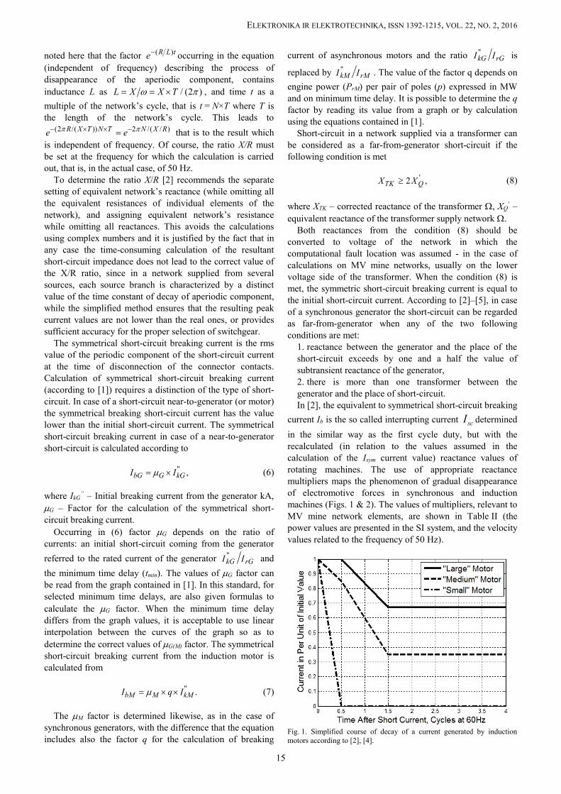
current Ib is the so called interrupting current scI determinedin the similar way as the first cycle duty, but with therecalculated (in relation to the values assumed in thecalculation of the Isym current value) reactance values ofrotating machines. The use of appropriate reactancemultipliers maps the phenomenon of gradual disappearanceof electromotive forces in synchronous and inductionmachines (Figs. 1 & 2). The values of multipliers, relevant toMV mine network elements, are shown in Table II (thepower values are presented in the SI system, and the velocityvalues related to the frequency of 50 Hz).
Fig. 1. Simplified course of decay of a current generated by inductionmotors according to [2], [4].
15

ELEKTRONIKA IR ELEKTROTECHNIKA, ISSN 1392-1215, VOL. 22, NO. 2, 2016
Fig. 2. Multipliers of Motors’ Impedance corresponding to decayfrom Fig. 1.
TABLE II. VALUES OF REACTANCE MULTIPLIERS TO CALCULATETHE CURRENT OF THE FIRST CYCLE AND BREAKING CURRENT
IN ACCORDANCE WITH [2]–[5].
CriterionMultipliers for
calculating the firstcycle duty
Multipliers forcalculating the
breaking currentSynchronous machines
turbogenerators 1,0 1,0synchronous motors 1,0 1,5
Induction machines> 735,5 kW and ≤ 1500
turns/min 1,0 1,5
>183.9 kW and 3000turns/min 1,0 1,5
≥ 36.8kW 1,2 3< 36.8kW ∞ ∞
Asymmetric breaking current is the geometric sum ofinitial short-circuit current and short-circuit current’saperiodic component. The value of d.c. (aperiodic)component of short-circuit current at time t is calculatedfrom the following equation [1]
2"
. . 2 ,kk
RftX
d c ki I e
(9)
where f – nominal frequency Hz.According to [2] asymmetric breaking current Iasym is
determined on the basis of symmetric current and amultiplier M which value depends on two parameters: minimum time delay (presented as the number ofcycles C), X/R ratio in the place where short-circuit occurred.This multiplier values are selected on the basis of the
graphs contained in [2]. It should be noted that separategraphs describe the value of MR multiplier the in case of far-from- generator short-circuit (where disappears only theaperiodic component) and ML for near-to-generator short-circuit (aperiodic component disappears, while the periodiccomponent decreases). For remote short-circuits thismultiplier can be evaluated from the formula
4
1 2 .
CX
RRM e
(10)
In case when short-circuit at a specific point in thenetwork is supplied from both distant and nearby sources, itis proposed to interpolate the multiplier M using thefollowing formula [2], [4]
,R L LM M M NACD M (11)
where M – resultant (interpolated) value of multiplier, MR –multiplier value for remote short-circuits, ML – multipliervalue for local short-circuits, NACD – ratio of the sum ofcurrents from remote sources (No AC Decay) to summaryshort-circuit current Isym.
In that case the value of asymmetric breaking current iscalculated as follows
.asym symI M I (12)
III. CALCULATION OF MAXIMUM SHORT-CIRCUITCURRENTS IN OPEN NETWORK SUPPLIED FROM SEVERAL
INDEPENDENT SOURCES
In compliance with the recommendations contained in [1],the short-circuit calculations should be done by setting theequivalent impedance Zk using the equivalent networkdiagram transformation. Impedances of the individualelements, which are connected via a transformer to thenetwork where the short-circuit location was assumed forcalculation, must be converted to a voltage of the network.The initial short-circuit current in short-circuit location F isthe geometric sum of component short-circuit currents
'' '' .k kii
I I (13)
In the case of a short circuit in an open network suppliedfrom several sources it is allowed to calculate the initialshort-circuit current at the fault location F, as the algebraicsum of the individual component short-circuit currents,which can by expressed by the following formula
'' '' .k kii
I I (14)
When calculating the maximum short-circuit currents, allthe generators connected to the network affected by a short-circuit must be assumed as the source of short-circuitcurrent, and there should be evaluated the participation ofsynchronous and induction motors powered from thenetwork (either directly or through a transformer) in whichthe fault location was assumed for calculation.
In compliance with [1], in calculations of the maximumshort-circuit currents, the synchronous motors should beconsidered as synchronous generators, therefore to thesemachines apply the same principles of calculation andformulas that apply to generators. In relation to the MVnetwork, the medium voltage induction motors must betaken into account in the calculation of the maximum short-circuit current [1], thus they should be regarded as sourcesof short-circuit current.
16

ELEKTRONIKA IR ELEKTROTECHNIKA, ISSN 1392-1215, VOL. 22, NO. 2, 2016
In the case of an open network supplied from severalindependent sources, the short-circuit peak current at thefault location F is determined as the sum of the individualshort-circuit peak current components
.p pii
i i (15)
The symmetric short-circuit breaking current is calculatedin the similar way, treating it as the sum of the componentcurrents flowing from various sources
.b bii
I I (16)
IV. EQUIVALENT IMPEDANCES OF SELECTED NETWORKELEMENTS
Equivalent impedance (as a complex number) of thesupply network can be can be written as
.Q QQZ R jX (17)
It is determined on the basis of the initial short-circuitcurrent at the supply location Ik
” kA or the initialsymmetrical short-circuit power Sk
” MVA. The equivalentimpedance of the supply network (expressed as a complexnumber) can be calculated from one of the followingequations:
2''
1,
3 1
nQ Q QQ
kQ Q Q
cU R X jZ
I R X
(18)
or
2
2''
1,
1
nQ Q QQ
k Q Q
cU R X jZ
S R X
(19)
where c – voltage factor; c =1.1, UnQ – nominal networkvoltage at the point of connection Q kV, RQ/XQ – resistanceto reactance ratio in equivalent network.
In the case of high-voltage power supply network (UnQ >35 kV), with the unknown RQ/XQ ratio, it is assumed thatRQ ≈ 0 .
Equivalent impedance of a two-winding transformer iscalculated based on the nominal parameters of thetransformer. In accordance with the recommendations of [1],calculation of short-circuit currents requires multiplying thevalue of equivalent impedance of the transformer by thecorrection factor KT, which can be written as follows
,T T TTKZ K R jX (20)
where RT – equivalent resistance of the transformer , XT –equivalent reactance of the transformer , KT – impedancecorrection factor for two-winding network transformer.
The required KT factor correcting transformer’sparameters is calculated from the following
max0.95 ,1 0.6T
T
cK
x
(21)
where cmax – voltage factor (Table I), xT – relative reactanceof the transformer, rTrTTT SUXx 2 .
Thus the corrected equivalent impedance (expressed as acomplex number) can be determined from
221 1 ,
100krRr rT
TTKrT Rr
uu UZ K jS u
(22)
where uRr – rated resistive component of the short-circuitvoltage of a transformer in per cent, ukr – rated short-circuitvoltage of transformer in per cent, UrT – rated voltage oftransformer on the high-voltage or low-voltage side kV, SrT –rated apparent power of the transformer MVA.
When calculating short-circuit currents according to [1],the impedance of a synchronous generator, similarly totransformer’s impedance, should be multiplied by thecorrection factor KG. Then the equivalent impedance of asynchronous generator can be written in the following form
'' ,G G dGKZ K R jX (23)
where RG – equivalent resistance of synchronousgenerator , Xd
” – subtransient reactance of the synchronousgenerator .
Correction factor for equivalent impedance ofsynchronous generator (synchronous motor) KG(S) iscalculated from
max( ) ''
( ) ( ),
1 sinn
G SrG S d rG S
U cK
U x
(24)
where UrG(S) – rated voltage of the generator (synchronousmotor) kV, xd
” –relative subtransient reactance of thegenerator (motor), xd
”= Xd”/(U2
rG(S)/SrG(S)), rG(S) – phaseangle between IrG and 3)(SrGU , SrG(S) – rated apparent
power of the generator (motor) MVA.To determine the impedance ZG(S)K is necessary to know
the rated data of the machine and compared RG(S)/Xd” for thesynchronous generator (synchronous motor). AppropriateRG(S)/Xd” ratios and the criteria for their selection arepresented in Table III.
Corrected equivalent impedance of synchronous generator(synchronous motor) can be derived from the following
2''( ) ( )%
( )( ) ''( )
1 ,100
rG S G SdG SG S K
rG S d
U RXZ K j
S X
(25)
where RG(S)/Xd” – value selected from Table III.
In the case of synchronous motors, with the knowledge ofthe rated power PrS (on the shaft of the machine), (25) takesthe following form
17

ELEKTRONIKA IR ELEKTROTECHNIKA, ISSN 1392-1215, VOL. 22, NO. 2, 2016
'' 2%
''cos
1 ,100
d rS rS rS SSSK
rS d
X U RZ K j
P X
(26)
where PrS – rated active power of synchronous motor MW,UrS – rated voltage of synchronous motor kV, cosrS – ratedpower factor, rS – rated efficiency of the synchronousmotor, RS/Xd
” – value selected from Table III.The equivalent impedance (expressed as complex
number) of the induction motor used for calculation ofmaximum short-circuit currents can be presented by thefollowing formula
.M MMZ R jX (27)
Its evaluation is made on the basis of rated values of theinduction machine and the RM/XM ratio. The formula for theequivalent impedance of the induction motor can beexpressed as follows
2
2
cos1 1 ,1
rM rM rM MM
LR rM MrM M M
U RZ jI I XP R X
(28)
where PrM – rated active power of asynchronous motor,MW, UrM – rated voltage of asynchronous motor kV, ILR/IrM
– ratio of the locked-rotor to the rated current of the motor,cosrM – rated power factor, rM – rated efficiency of theasynchronous motor, RM/XM – value selected from Table III.
TABLE III. VALUES OF RM/XM AND RG/XD” RATIOS FORCALCULATION OF SHORT-CIRCUIT CURRENTS IN COMPLIANCE
WITH [1].Criterion RG(S)/Xd” RM/XM
Synchronous generatorsUrG >1 kV and SrG 100 MVA 0.05UrG >1 kV and SrG < 100 MVA 0.07
UrG ≤ 1 kV 0.15Induction machines
UrM >1 kV and PrM/p 1 MW 0.10UrM >1 kV and PrM/p < 1 MW 0.15
UrM ≤ 1 kV 0.42
Equivalent impedance of the short-circuit current-limitingreactor ZR is basically equal to its reactance XR, because RR
<< XR. Its value can be calculated from the following
,100 3
kR rRR
rR
u UXI
(29)
where ukR – short-circuit voltage of a short-circuit limitingreactor in per cent, UrR – rated voltage of the reactor kV, IrR
– rated current of the reactor kA.Equivalent impedance of the cable line used for
calculation of the maximum short-circuit currents can bederived from the following
' ' ,L L L LLZ R jX l R jX (30)
where RL’;XL
’ – unit resistance and reactance of the cableline /km, l – length of cable line km.
The ANSI/IEEE standards do not provide for the use of
the factors correcting impedance of transformers andsynchronous machines (as defined in [1]). But there shouldbe applied appropriate (separate for first cycle current andbreaking current) reactance multipliers for synchronousmotors and induction machines (Table II). Supply networkimpedance is determined for the value c = 1.
V. CALCULATION EXAMPLE
To illustrate the differences in the calculation of themaximum short-circuit current according to IEC and on theother hand ANSI/IEEE standards, there were conductedcalculations of characteristic short-circuit currents, necessaryfor the selection of W switch on the sample segment of minepower system. Diagram of electric power network underconsideration (with the rating of the individual elements,used to calculate the impedance) is shown in Fig. 3, andselected according to both standards parameters ofindividual elements in Table IV.
Fig. 3. Diagram of an exemplary network for comparing calculationsaccording to IEC and ANSI/IEEE standards (GRK - main mineswitchboard, GRP – main level switchboard, RP - intermediateswitchboard, Q – power supply network, T - transformer, MA1 ÷ MA5 -asynchronous motors, MS1, MS2 - synchronous motors, L1, L2 - cablelines, R – short-circuit limiting reactor, W – circuit-breaker).
Equivalent diagram for the calculation of the maximumshort-circuit currents (according to [1]) with the assumed forcomputation fault location (as in Fig. 3) is shown in Fig. 4.This diagram may also be used to calculate the maximumshort-circuit current according to [2]–[5], assuming thevalues of the factors KT = KS =1 and c = 1. The values ofequivalent impedances of different elements of the networkare shown in Table IV.
The initial short-circuit current was determined throughthe conversion of the network diagram. Following theprinciples contained in [1] concerning calculation of short-
18

ELEKTRONIKA IR ELEKTROTECHNIKA, ISSN 1392-1215, VOL. 22, NO. 2, 2016
circuit currents in an open network supplied from severalindependent sources, there have been also calculated thecomponent initial short-circuit currents.
TABLE IV. IMPEDANCE VALUES OF INDIVIDUAL ELEMENTS OFTHE SYSTEM SHOWN IN FIGURE 3 CHOSEN ACCORDING TO [1]
AND [2]–[5].
Networkelement
IEC ANSI/IEEE
R
X
for calculating„first cycle current”
for calculating„breakingcurrent”
R () X () R () X ()Q - 0.013 - 0.012 - 0.012T 0.011 0.188 0.011 0.191 0.011 0.191
MS1, MS2 0.217 3.107 0.213 3.044 0.213 4.566MA1, MA2,
MA3 0.502 3.357 0.502 3.357 0.502 5.035
MA4,MA5 0.585 3.911 0.585 3.911 0.585 5.867R - 0.139 - 0.139 - 0.139L1 0.089 0.077 0.089 0.077 0.089 0.077
Fig. 4. Equivalent diagram of a short-circuited circuit (for positive-sequence component).
The diagrams for calculating equivalent networkreactance and resistance according to [2] is shown in Fig. 5and Fig. 6.
Fig. 5. The diagram of reactance network used to determine the short-circuit current and the value of X/R ratio in the calculations compatiblewith [2].
In conformity with these principles, the othercharacteristic short-circuit currents were calculated, and theresults were tabulated (Table V). This table also contains theresults of short-circuit currents calculations conducted inaccordance with ANSI/IEEE standard. It should be notedthat the value of the aperiodic component Isc was determinedfor comparative purposes, as a geometric difference
22scasym II , since [2] does not provide for its direct
determination. The values of Isym, Ipeak components weredetermined only for comparative purposes, since [2] doesnot provide for their direct calculation (with an exception ofthe cases when it is necessary to determine the value ofNACD ratio and interpolation of multiplier M). The value ofX/R ratio as determined by a method of separatetransformation of the reactive and resistive networksamounts to 15.5. By way of comparison it can be indicatedthat after the transformation the impedance diagram (as in[1]) the obtained result amounted to X/R = 13.4. On theother hand the value of NACD factor used in theinterpolation of multipliers for calculating the current Iasym inthe considered example was determined as
17.1 24.1 0.71.symQ symNACD I I (31)
Fig. 6. The diagram of resistance network used to determine and the valueof X/R ratio in the calculations compatible with [2].
TABLE V. THE RESULTS OF CALCULATIONS OF MAXIMUMSHORT-CIRCUIT CURRENTS IN THE EXAMPLE SHOWN ON FIG. 3.
Sour
ce
according to ANSI/IEEEstandards according to IEC standard
Isym Ipeak Isc Idc Iasym Iki” ipi Ibi id.c. Ibasym
kA kA
Q 17.1 44.5 17.1 - - 19.0 49.7 19.0 - -MS1 1.1 2.9 0.8 - - 1.2 3.1 1.0 - -MS2 1.1 2.9 0.8 - - 1.2 3.1 1.0 - -MA1 1.0 2.4 0.7 - - 1.1 2.6 0.7 - -MA2 1.0 2.4 0.7 - - 1.1 2.6 0.7 - -MA3 1.0 2.4 0.7 - - 1.1 2.6 0.7 - -MA4 0.8 3.8 0.6 - - 0.9 4.1 0.5 - -MA5 0.8 0.6 - - 0.9 0.5 - - 23.9 61.3 22.0 10.4 24.3 26.5 67.8 24.1 11.6 26.7
1.1 26.3 67.4 24.2 11.4 26.9
VI. CONCLUSIONS
Due to the economic aspects of switchgear selection and -related to ensuring safety in underground mines -requirements concerning continuity of supply, the problemof calculating the maximum short-circuit currents is ofparticular importance. It is reasonable, therefore, to compareshort-circuit calculations carried out by different methods.Comparative analysis of the calculation results point to thefact that the calculation of all the currents according to [2]lead to results lower by about 10 % from the results ofcalculations carried out according to [1]. This is mostly
19
ELEKTRONIKA IR ELEKTROTECHNIKA, ISSN 1392-1215, VOL. 22, NO. 2, 2016
related to the use of the factor stipulated in [1], which is notused according to [2]. After taking into account this fact (ie,scaling the obtained results) discrepancies between thesestandards do not exceed 1.5 %. But interesting differencescan be noticed when individual motor contributions tosymmetrical breaking current are analysed. In the case ofinduction motors (MA1...MA5) current values according toANSI standard are higher than according to IEC standard.This is contrary to the case of synchronous motors(MS1&MS2) where contributions according to IEC arehigher than contributions according to ANSI. It should bealso noted that [2]–[5] are much simpler computationally(basically do not require calculations performed on complexnumbers, as they only consider network reactances, and donot require correction of impedance of transformers andsynchronous generators). The depicted example shows thatquite different (simplified) modelling methodology ofdisappearance of the components from rotating machines –through the use of appropriate impedance multipliers – leadsto very similar results.
REFERENCES[1] Int Std IEC 60909-0, Short-Circuit Currents in Three-Phase AC
Systems Part 0: Calculation of currents. 2002.[2] ANSI/IEEE Std C37.010, IEEE Application Guide for AC High
Voltage Circuit Breakers Rated on a Symmetrical Current Basis.1979.
[3] ANSI/IEEE Std 141, IEEE Recommended Practice for ElectricPower Distribution for Industrial Plants (Red Book), 1993.
[4] ANSI/IEEE Std 399, IEEE Recommended Practice for Industrial andCommercial Power Systems Analysis (Brown Book), 1997.
[5] ANSI/IEEE Std 551, IEEE Recommended Practice for CalculatingShort-Circuit Currents in Industrial and Commercial Power Systems(Violet Book), 2006.
[6] PN-74/E-05002 Electrical Power Equipment. Selection of High-voltage Apparatuses Depending on Short-circuit Conditions, 1974
[7] G. Knight, H. Sieling “Comparison of ANSI and IEC 909 Short-circuit current calculation procedures”, IEEE Trans. on IndustryApplications, vol. 29, pp. 625–630, 1993. [Online]. Available:http://dx.doi.org/10.1109/28.222435
[8] A. J. Rodolakis, “A Comparison of North American (ANSI) andEuropean (IEC) fault calculation guidelines”, IEEE Trans. IndustryApplications, vol. 29, pp. 515–521, 1993. [Online]. Available:http://dx.doi.org/10.1109/28.222420
[9] PN-G-42042, Protective and Safety Measures in the Mining PowerNetworks – Short-circuit and Overload Protection - Requirementsand Rules for Selection, 1998.
[10] D. Nedic, G. Bathurst, J. Heath, “A comparison of short circuitcalculation methods and guidelines for distribution networks”, inProc. 19 th Int. Conf. on Electricity Distribution, Vienna, 2007.
[11] N. D. Tleiss, Power Systems Modelling and Fault Analysis. Theoryand Practice. Elsevier, 2008.
[12] J. C. Das, Power system analysis short-circuit load flow andharmonics. BocaRaton FL: CRC Press, 2011. [Online]. Available:http://dx.doi.org/10.1201/b11021
[13] C. G. Kaloudas, P. N. Papadopoulos, T. A. Papadopoulos, “Short-circuit analysis of an isolated generator and comparative study ofIEC, ANSI and dynamic simulation”, in Proc. 7th MediterraneanConf. and Exhibition on Power Generation, Transmission,Distribution and Energy Conversion MedPower, Agia Napa 2010.[Online]. Available: http://dx.doi.org/10.1049/cp.2010.0922
[14] T. A. Papadopoulos, C. G. Kaloudas, A. G. Marinopoulos, “Static anddynamic calculation of short-circuit currents in synchronousgenerators”, in Proc. Int. Conf. Power Systems Transients, Delft2011.
[15] S. L. Shankar, M. M. Iqbal, “ANSI and IEC standards based shortcircuit analysis of a typical 2×30 mw thermal power plant”, Middle-East J. Sci. Res., vol. 23, no. 8, 2015.
20