comparative study between two models of a linear oscillating tubular motor
TRANSCRIPT
8/12/2019 Comparative study between two models of a linear oscillating tubular motor
http://slidepdf.com/reader/full/comparative-study-between-two-models-of-a-linear-oscillating-tubular-motor 1/7
IOSR Journal of Electrical and Electronics Engineering (IOSR-JEEE)e-ISSN: 2278-1676,p-ISSN: 2320-3331, Volume 9, Issue 1 Ver. IV (Feb. 2014), PP 77-83www.iosrjournals.org
www.iosrjournals.org 77 | Page
Comparative study between two models of a linear oscillating
tubular motor
A .Mazouz1. D.Hedjazi
1.
1 LEB research laboratory-Section: Linear Electromagnetic Traction
Department of electrical Engineering – BATNA University – ALGERIA
Abstract : The paper describes the performance of linear oscillating tubular motor and the development of its
structure and characteristics of a year oscillating linear parametric motor.
Thus, we have compared our study with that which uses only one equation of operation from an
oscillator motor linear and compared between the results. The oscillating parametric engine is composed of a
reel and a core which can slip inside that thereof. By connecting the reel to a source of single-phase tension
through a condenser and a variable resistor, under the conditions of electromechanical resonance, after an
initial displacement of the core, it is then possible to obtain a translator movement of this last (direct and
opposite). The speed of oscillation can be controlled by variation of the capacity or resistance.Key words: linear motor; linear parametric motor, oscillating motor
I. Introduction:The induction parametric motor has excellent executions in comparison with the ordinary single-phase
motor , since this one uses parametric oscillations and abnormal phenomena, while the intermittent rotation
where the inverted normal rotation ensures with asynchronous and synchronous conception; or an inverse
direct displacement, this can occur in reason of the instability of the parametric oscillations. This abnormal behavior must be avoided when an engine with parametric induction is used for practical applications.
The nature of electromechanical resonance depends on the presence on two oscillating contours, L.C contour
with electric oscillations and the core with mechanical oscillations which are due to the electromechanical action
applied to this core, which is similar to the action of a spring. The energy exchange between two contours is
carried out fortunately to the periodic variation of inductance. the displacement of the core in the two directions,
involves the variation of inductance. With a certain value of the latter, a phenomenon of Ferro resonanceengages and an important force attracts the core towards a second point of Ferro symmetrical resonance per
report/ratio at the point medium of the reel. It is then possible to obtain a translator movement of this last (direct
and opposite). The speed of oscillation can be controlled by variation of the capacity, the resistance or the
supply voltage like by action on the frequency.
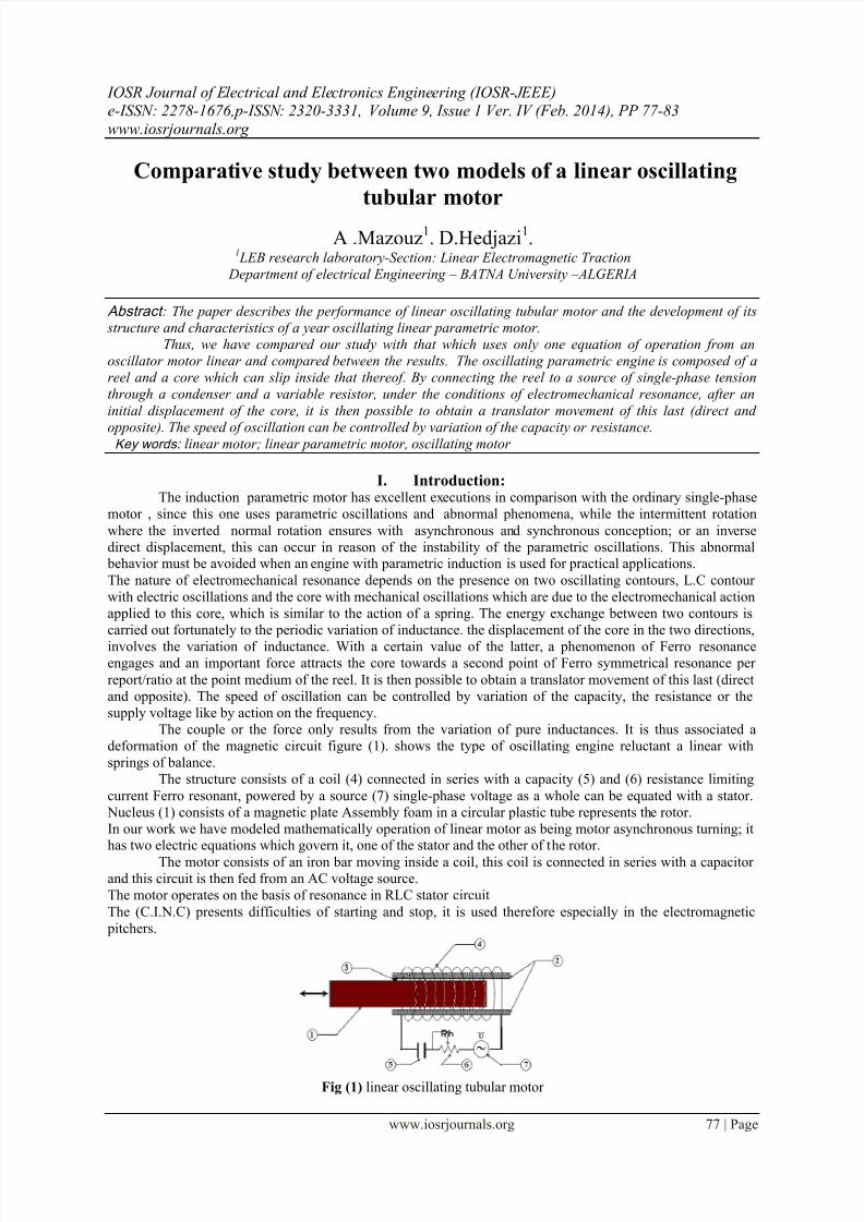
The couple or the force only results from the variation of pure inductances. It is thus associated a
deformation of the magnetic circuit figure (1). shows the type of oscillating engine reluctant a linear with
springs of balance.
The structure consists of a coil (4) connected in series with a capacity (5) and (6) resistance limiting
current Ferro resonant, powered by a source (7) single-phase voltage as a whole can be equated with a stator.
Nucleus (1) consists of a magnetic plate Assembly foam in a circular plastic tube represents the rotor.
In our work we have modeled mathematically operation of linear motor as being motor asynchronous turning; ithas two electric equations which govern it, one of the stator and the other of the rotor.
The motor consists of an iron bar moving inside a coil, this coil is connected in series with a capacitorand this circuit is then fed from an AC voltage source.
The motor operates on the basis of resonance in RLC stator circuit
The (C.I.N.C) presents difficulties of starting and stop, it is used therefore especially in the electromagnetic
pitchers.
Fig (1) linear oscillating tubular motor
8/12/2019 Comparative study between two models of a linear oscillating tubular motor
http://slidepdf.com/reader/full/comparative-study-between-two-models-of-a-linear-oscillating-tubular-motor 2/7
Comparative study between two models of a linear oscillating tubular motor
www.iosrjournals.org 78 | Page
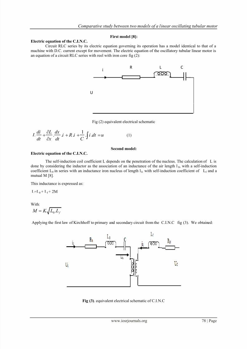
First model [8]:
Electric equation of the C.I.N.C.
Circuit RLC series by its electric equation governing its operation has a model identical to that of a
machine with D.C. current except for movement. The electric equation of the oscillatory tubular linear motor is
an equation of a circuit RLC series with reel with iron core fig (2):
Fig (2) equivalent electrical schematic
1. . . . .
di L dx L i R i i dt u
dt x dt C
(1)
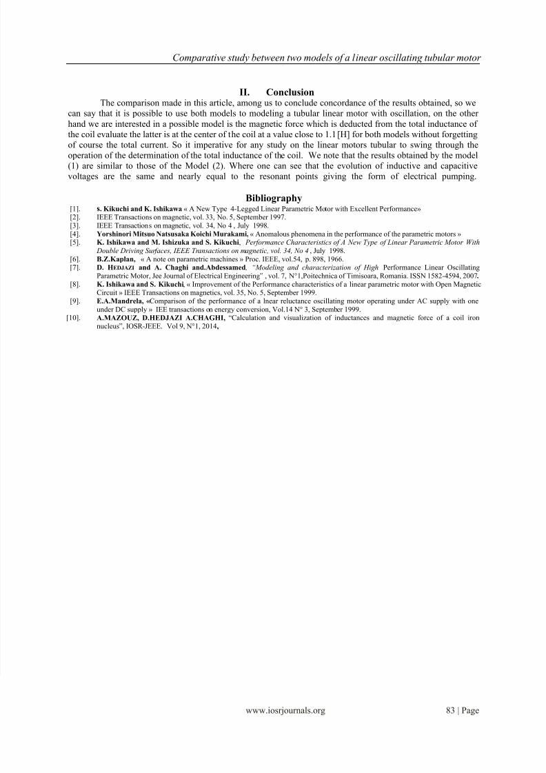
Second model:
Electric equation of the C.I.N.C.
The self-induction coil coefficient L depends on the penetration of the nucleus. The calculation of L isdone by considering the inductor as the association of an inductance of the air length l0, with a self-induction
coefficient L0 in series with an inductance iron nucleus of length lf , with self-induction coefficient of Lf and a
mutual M [8].
This inductance is expressed as:
L=L0 + Lf + 2M
With:
f L L K M .0
Applying the first law of Kirchhoff to primary and secondary circuit from the C.I.N.C fig (3). We obtained:
Fig (3). equivalent electrical schematic of C.I.N.C
C
U
Ri
L

8/12/2019 Comparative study between two models of a linear oscillating tubular motor
http://slidepdf.com/reader/full/comparative-study-between-two-models-of-a-linear-oscillating-tubular-motor 3/7
Comparative study between two models of a linear oscillating tubular motor
www.iosrjournals.org 79 | Page
(2)After simplifying we get:
C: the capacitance,
L0: the inductance of the air,Lf : the inductance of the core,
M: the mutual inductance,
U1 and U2: respectively the voltage of the coil and the core circuits,
i1 and i2 : respectively the currents of the coil and the core circuits,
R b and R n : are respectively the resistances of the coil and the core,
This expression 2 can be written in the following matrix form:
[] [ ][] [ ][] [][]
(3)
This is a deferentially equation non linear and non homogeneous with second member.The magnetic force f m is expressed by the following formula:
()
(4)t w F t f mm .cos.)( 0
f m: is the magnetic force acting on the bar,
Where:
m: is the masse of the bar,
x: the position of the centre of the bar,
The resultant movement is the summer of two oscillating periodic of beat (wm , w0) and a deferent amplitudes.
: Frequency mechanical oscillation of the nucleus.
Mechanical model of the C.I.N.C.
Non damped oscillatory mechanical system has the form fig (3)
Fig (3) : Oscillating mechanical system unamortized
() (5)
With a condition: r wm
k w 0
: Source frequency.
: Frequency critical resonance.
C b U vdx
dM i
dt
di M
dt
di Liv
dx
dL RU ....)..( 2
2101
01
vdx
dM i
dt
di M
dt
di Liv
dx
dL RU f
f
N ....)..( 1
12
22
dt
dU C i
C .0
1
dt iC dt
dx
dx
dM i
dt
di M
dt
dx
dx
dLi
dt
di Li RU
b .
1......
1220
11
011
dt
dx
dx
dM i
dt
di M
dt
dx
dx
dLi
dt
di Li RU
f
f N ......
11
22
22

8/12/2019 Comparative study between two models of a linear oscillating tubular motor
http://slidepdf.com/reader/full/comparative-study-between-two-models-of-a-linear-oscillating-tubular-motor 4/7
Comparative study between two models of a linear oscillating tubular motor
www.iosrjournals.org 80 | Page
Comparison of two models:
The first model equation (1), gave simulation results presented in figures (1.1, 1.2, 1.3, 1.4). Cons by
the simulation results of our model equation (2) are illustrated by the figures (2.1, 2.2, 2.3, 2.4, 2.5, 2.6, 2.7),
and comparison of results between the two models allowed us to conclude concordance of the two works.
The linear motor oscillating parametric single constitution, it operates on the basis of an electric Ferro-resonance occurs in a stator consisting of an RLC circuit where the coil iron core.
Solving the system of mathematical equations describing the behavior of the motor requires computer
skills. In the case of the Ferro- resonance transients are generally long-time simulation studies are significantcost.
The Ferro resonance phenomenon is very sensitive to parameter values and initial conditions are
unknown in practice, we need to study for each possible combination, which is not normal. To arrive at
solutions, different mathematical methods are used. Our case is to treat the problem by simulation using
MATLAB.
Fig1.1 variation of the total inductance in function of(x)
Fig 1.2 variation of the speed in function of (x)
Fig1.3 variation of the inductance Lf of function of (x)

8/12/2019 Comparative study between two models of a linear oscillating tubular motor
http://slidepdf.com/reader/full/comparative-study-between-two-models-of-a-linear-oscillating-tubular-motor 5/7
Comparative study between two models of a linear oscillating tubular motor
www.iosrjournals.org 81 | Page
Fig1.4 variation of the force in function of the time
Fig 2.1 variation of the inductance Lf in function of the time.
Fig 2.2 variation of the inductance L0 in function of the time.
Fig 2.3 variation of the total inductance L in function of the time.
0 0.05 0.1 0.15 0.2 0.25 0.3 0.35 0.40
0.2
0.4
0.6
0.8
1
1.2
1.4
L f
t
0 0.05 0.1 0.15 0.2 0.25 0.3 0.35 0.40
0.005
0.01
0.015
0.02
0.025
0.03
0.035
t
L 0
0 0.05 0.1 0.15 0.2 0.25 0.3 0.35 0.40.1
0.2
0.3
0.4
0.5
0.6
0.7
0.8
0.9
1
1.1
t
L

8/12/2019 Comparative study between two models of a linear oscillating tubular motor
http://slidepdf.com/reader/full/comparative-study-between-two-models-of-a-linear-oscillating-tubular-motor 6/7
Comparative study between two models of a linear oscillating tubular motor
www.iosrjournals.org 82 | Page
Fig 2.4 variation of the mutual in function of the time.
Fig 2.5 variation of the force in function of the time.
Fig 2.6 variation of the speed in function of (x).
Fig 2.7 variation of the speed in function of the time.
0 0.05 0.1 0.15 0.2 0.25 0.3 0.35 0.40.01
0.02
0.03
0.04
0.05
0.06
0.07
0.08
M
t
0 0.05 0.1 0.15 0.2 0.25 0.3 0.35 0.4 0.45-2
-1.5
-1
-0.5
0
0.5
1
1.5
2
v
x
0 0.1 0.2 0.3 0.4 0.5 0.6 0.7 0.8-2
-1.5
-1
-0.5
0
0.5
1
1.5
2
t
v
8/12/2019 Comparative study between two models of a linear oscillating tubular motor
http://slidepdf.com/reader/full/comparative-study-between-two-models-of-a-linear-oscillating-tubular-motor 7/7
Comparative study between two models of a linear oscillating tubular motor
www.iosrjournals.org 83 | Page
II. ConclusionThe comparison made in this article, among us to conclude concordance of the results obtained, so we
can say that it is possible to use both models to modeling a tubular linear motor with oscillation, on the other
hand we are interested in a possible model is the magnetic force which is deducted from the total inductance of
the coil evaluate the latter is at the center of the coil at a value close to 1.1[H] for both models without forgettingof course the total current. So it imperative for any study on the linear motors tubular to swing through the
operation of the determination of the total inductance of the coil. We note that the results obtained by the model
(1) are similar to those of the Model (2). Where one can see that the evolution of inductive and capacitive
voltages are the same and nearly equal to the resonant points giving the form of electrical pumping.
Bibliography[1]. s. Kikuchi and K. Ishikawa « A New Type 4-Legged Linear Parametric Motor with Excellent Performance»[2]. IEEE Transactions on magnetic, vol. 33, No. 5, September 1997.
[3]. IEEE Transactions on magnetic, vol. 34, No 4 , July 1998.
[4]. Yorshinori Mitsuo Natsusaka Koichi Murakami, « Anomalous phenomena in the performance of the parametric motors »[5]. K. Ishikawa and M. Ishizuka and S. Kikuchi , Performance Characteristics of A New Type of Linear Parametric Motor With
Double Driving Surfaces, IEEE Transactions on magnetic, vol. 34, No 4 , July 1998.
[6]. B.Z.Kaplan, « A note on parametric machines » Proc. IEEE, vol.54, p. 898, 1966.
[7].
D. HEDJAZI and A. Chaghi and.Abdessamed , “Modeling and characterization of High Performance Linear OscillatingParametric Motor, Jee Journal of Electrical Engineering” , vol. 7, N°1,Poitechnica of Timisoara, Romania. ISSN 1582-4594, 2007.
[8]. K. Ishikawa and S. Kikuchi, « Improvement of the Performance characteristics of a linear parametric motor with Open MagneticCircuit » IEEE Transactions on magnetics, vol. 35, No. 5, September 1999.
[9]. E.A.Mandrela, «Comparison of the performance of a lnear reluctance oscillating motor operating under AC supply with one
under DC supply » IEE transactions on energy conversion, Vol.14 N° 3, September 1999.[10]. A.MAZOUZ, D.HEDJAZI A.CHAGHI, “Calculation and visualization of inductances and magnetic force of a coil iron
nucleus”, IOSR-JEEE. Vol 9, N°1, 2014,