compact rail - concept latch lock & hinge · content 1 product explanation structural shapes...
TRANSCRIPT
COMPACT RAIL
www.rollon.com
About Rollon
Continual expansion and optimization of the portfolio
Founded in 1975, Rollon manufactured high-precision linear roller bea-
rings for the machine tool industry. Early on, Rollon started manufacturing
linear bearings based on the bearing-cage design. In 1979, the Com-
pact Rail self-aligning linear bearings joined the Telescopic Rail indus-
trial drawer slides and Easy Rail linear bearings and became the basis
of the strong foundation on which the company is building upon today.
Continuing optimization of these core products still remains one of the
most important goals at Rollon. The development of the patented Compact
Rail linear bearing, which uses different proprietary rail profiles and high-
precision radial ball bearing sliders, enables the compensation of height
and angle mounting defects in applications, and is only one example of
the continuing efforts to innovative the development of our existing pro-
duct families. In the same manner, we continually introduce innovative
new product familiesdisplaying our continuing product development and
optimization in the industry. These include:
■ 1994 Light Rail - full and partial extension telescopic in lightweight
design
■ 1996 Uniline - belt driven linear actuators
■ 2001 Ecoline - economical aluminum linear actuators
■ 2002 X-Rail - inexpensive formed steel linear guides
■ 2004 Curviline - curved monorail profile rail guide with roller carriages
■ 2007 Monorail - miniature sizes and full sized
Each further innovation of our linear bearings is built upon the our exten-
sive knowledge of the nine product families in production today as well as
on the current market demands. Rollon is the ultimate linear technology
for any application needs.
Development of global business
1975 Parent company, Rollon S.r.l., founded in Italy
1991 Founding of Rollon GmbH in Germany
1995 Expansion of headquarters to new 4,000 m2 factory
Assembly starts in Germany
Quality management certified to ISO 9001
1998 Rollon B.V. in the Netherlands and Rollon Corporation in the
USA are founded
Expansion of German branch to new 1,000 m2 plant
1999 Founding of Rollon S.A.R.L. in France
Environmental management certified to ISO 14001
2000 Rollon s.r.o. founded in Czech Republic
2001 Expansion of headquarters to new 12,000 m2
manufacturing plant
2007 Restructuring of the GmbH and alignment of production in
Germany to customer-specific adaptations
Takeover of the assets of a manufacturer of linear rail
systems
2008 Expansion of sales network in Eastern Europe and Asia
Content
1 Product explanation Structural shapes and designs
2 Technical data Performance characteristics and remarks Configurations and behavior of the slider under yawing moment Mz Load capacities
3 Product dimensions Rail T, U, K Rail TR Rail length N-version slider, normal N-version slider, long C-version slider T-rail with N- / C-slider TR-rail with N- / C-slider U-rail with N- / C-slider K-rail with N- / C-slider, Offset of fixing holes 4 Accessories Rollers Wipers for C-slider, Alignment fixture AT, Alignment fixture AK Fixing screws Manual clamp elements
5
8
912
16181920222427282930
32
333435

4 www.rollon.com
Content
5 Technical instructions Linear accuracy Rigidity Supported sides, T+U-system tolerance compensation K+U-system tolerance compensation Preload Drive force Static load Calculation formulas Service life Lubrication, N-slider lubrication C-slider lubrication, Corrosion protection, Speed and acceleration, Operating temperatures
6 Installation instructions Fixing holes Adjusting the sliders Installing the single rail Parallel installation of two rails Installation of the T+U- or the K+U-system Joined Rails Installation of joined rails
Ordering key Ordering key with explanations Portfolio
3638
4245485052535658
59
60616265676870

5www.rollon.com
Product explanationCompact Rail is the product family of roller slider systems
Product explanation 1
Compact Rail is the product family of guide rails consisting of roller sli-
ders with radial bearings which slide on the internal, induction hardened
and ground raceways of a C-profile made from cold-drawn roller bearing
carbon steel.
Compact Rail consists of three product series: the fixed bearing rail, the
compensating bearing rail and the compensation rail. All products are
available in zinc plating, with nickel plating also available as an option.
There are five different sizes of guide rails and many different version and
lengths of the slide bearing.
The most important characteristics:
■ Compact size
■ Corrosion resistant surface
■ Not sensitive to dirt due to internal tracks
■ Hardened and ground raceways
■ Custom design TR-rail, also ground on the back of the rail and one
side surface
■ Self-aligning in two planes
■ Quieter than recirculating ball systems
■ High operating speeds
■ Wide temperature range
■ Easy adjustment of slider in the guide rail
■ Zinc plated surface, on request chemically nickel plated
Preferred areas of application:
■ Cutting machines
■ Medical technology
■ Packaging machines
■ Photographic lighting equipment
■ Construction and machine technology (doors, protective covers)
■ Robots and manipulators
■ Automation
■ Handling
Fig. 1

6 www.rollon.com
1 Product explanation
Fixed bearing rails ( T-rails)
Fixed bearing rails are used as the main load bearing in radial and axial
forces.
Compensation bearing rails (K-rails)
The compensation bearing rails are used for the load bearing of radial and
axial forces. Tolerance compensation in two planes can be implemented
in combination with the compensating rail.
System (T+U-system)
The combination of fixed bearing rail and floating bearing rail allows for
deviations in parallelism.
Floating bearing rails (U-rails)
The floating bearing rails are used for load bearing of radial forces and, in
combination with the fixed bearing rail or compensation rail, as a support
bearing for occurring moments.
Fig. 2
Fig. 4
Fig. 5
Fig. 6
System (K+U-system)
The combination of compensation rail and floating bearing rail allows for
deviations in parallelism and height offset.
Fig. 7
Fixed bearing rails ( TR-rails)
The TR rail is also available as a custom design. The TR rail is ground on
the back of the rail and one side surface to allow for a closer mating onto
the surface.
Fig. 3

7www.rollon.com
Product explanation 1
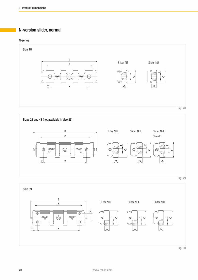
N-slider
Constructed with a closed, chemically nickel plated aluminum die cast
body that is available for sizes 18, 28, 43 and 63. Spring preloaded wipers
and a self-lubrication kit are integrated in the end caps (except for size 18,
see pg. 58). Configurable with three rollers as standard, in sizes 28 and
43 a longer carriage with up to five rollers is also available.Fig. 8
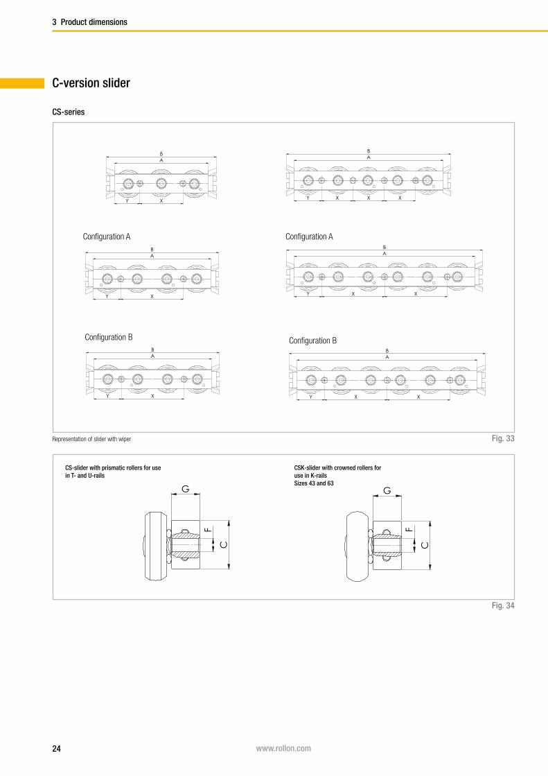
CS-slider
Constructed with zinc-plated steel body and sturdy wipers (optional) made
of polyamide. Available for all sizes. Depending on the load case, slider is
configurable with up to six rollers.
Fig. 9
Rollers
Also available individually in all sizes. Available as eccentric or concentric
rollers. Optionally available with splash-proof plastic seal (2RS) or with
steel cover disc (2Z).
Fig. 11
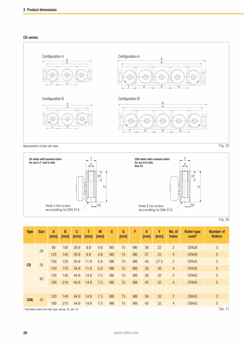
CD-slider
Constructed with asymmetrical zinc-plated steel body and sturdy wipers
(optional) made of polyamide. With this design the fixing of the moving
parts, upward or downward is possible. The Slider is available for sizes 28,
35 und 43. Available with three or five rollers, depending on load case and
load direction set with the corresponding configuration.Fig. 10
Wipers
Wipers are available for slider types CS and CD and are made of sturdy
polyamide. They keep the raceways free of contamination and thus en-
sure a longer service life.
Fig. 12
Alignment fixture
The alignment fixture AT / AK is used during installation of joined rails for
precise alignment of the rail transition from one to another.
Fig. 13

8 www.rollon.com
Technical data
2 Technical data
Slider
Rollers
Rail
Performance characteristics:
■ Available sizes for T-rail, TR-rail, U-rail: 18, 28, 35, 43, 63
■ Available sizes for K-rail: 43, 63
■ Max. operating speed: 9 m/s ( 354 in/s)
(depending on application)
■ Max. acceleration: 20 m/s2 ( 787 in/s2 )
(depending on application)
■ Max. radial load capacity: 15,000 N ( per slider)
■ Temperature range: -30 °C to +120 °C (-22 °F to +248 °F )
briefly up to max. +170 °C (+338 °F )
■ Available rail lengths from 160 mm to 3,600 mm (6.3 in to 142 in)
in 80-mm increments (3.15 in),
longer single rails up to max. 4,080 mm (160.6 in) on request
■ Roller pins lubricated for life
■ Roller seal/shield: 2RS (splash-proof ), 2Z ( steel cover disk )
■ Roller material: steel 100Cr6
■ Rail raceways induction hardened and ground
■ Rails and slider bodies are standard zinc-plated according to
ISO 2081
■ Rail material of T- and U-rails in sizes 18 to 43:
cold-drawn roller bearing steel C43 F
■ Rail material of K-rails, as well as T- and U-rails in size 63: CF53
Remarks:
■ The sliders are equipped with rollers that are in alternating contact
with both sides of the raceway. Markings on the body around the
roller pins indicate correct arrangement of the rollers to the external
load
■ By a simple adjustment of the eccentric rollers, the slider has clea-
rance set by the desired preload in the rail
■ Rails in joined design are available for longer transverse distances
(see pg. 68f)
■ The K rails are not suitable for vertical installation
■ Screws of property class 10.9 must be used
■ Differences in screw sizes must be observed
■ During rail installation it must be basically ensured that the fixing
holes of the adjacent construction are sufficiently caught hold of (see
pg. 60, tab. 41)
■ The general illustrations show N-sliders as example
Fig. 14

9www.rollon.com
Technical data 2
Configurations and behavior of the slider under yawing moment Mz
When an overhanging load in an application with a single slider per rail
cause an Mz moment in one direction, a 4 to 6 roller Compact Rail slider
is available These sliders are available in both configuration A and B in
regards to the roller arrangement to counter the acting Mz moment. The
moment capacity of these sliders in the Mz-direction varies significantly
through spacing L1 und L
2 in accordance with the direction of rotation of M
z.
Especially in the use of two parallel rails, for example with a T+U-system,
it is extremely important to pay attention to the correct combination of the
slider configuration A and B, in order to use the maximum load capacities
of the slider.
The diagrams below illustrate this concept of the A and B configuration
for sliders with 4 and 6 rollers. The maximum allowable Mz-moment is
identical in both directions for all 3 and 5 roller sliders.
Fig. 15
Slider with 4 rollers
Configuration A
Slider with 4 rollers
Configuration B
Fig. 16
Individual slider under load moment Mz
F
F
Mzs
L2
Mzd
F
F
L1
Mzs
F
F
L2
Mzd
F
F
L1
10 www.rollon.com
2 Technical data
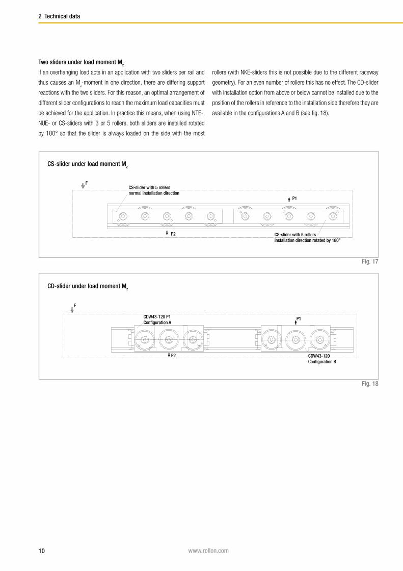
Two sliders under load moment Mz
If an overhanging load acts in an application with two sliders per rail and
thus causes an Mz-moment in one direction, there are differing support
reactions with the two sliders. For this reason, an optimal arrangement of
different slider configurations to reach the maximum load capacities must
be achieved for the application. In practice this means, when using NTE-,
NUE- or CS-sliders with 3 or 5 rollers, both sliders are installed rotated
by 180° so that the slider is always loaded on the side with the most
rollers (with NKE-sliders this is not possible due to the different raceway
geometry). For an even number of rollers this has no effect. The CD-slider
with installation option from above or below cannot be installed due to the
position of the rollers in reference to the installation side therefore they are
available in the configurations A and B (see fig. 18).
Fig. 17
Fig. 18
F
P2
P1
CS-slider with 5 rollersnormal installation direction
CS-slider with 5 rollersinstallation direction rotated by 180°
CS-slider under load moment Mz
CD-slider under load moment Mz
F
P2
P1CDW43-120 P1Configuration A
CDW43-120Configuration B

11www.rollon.com
Technical data 2
Arrangement DS
This is the recommended arrangement for use of two sliders under Mz-
moment when using one rail. Also see previous page: Two sliders under
load moment Mz.
Fig. 19
Arrangement DD
For using pairs of guide rails with two sliders each under load moment Mz,
the second system should be designed in arrangement DD. This results in
the following combination: Guide rail 1 with two sliders in arrangement DS
and guide rail 2 with 2 sliders in arrangement DD. This allows even load
and moment distribution between the two parallel rails.
Fig. 20
Arrangement DA
Standard arrangement if no other information is given. This arrangement
is recommended if the load point is located within the two outside points
of the sliders.
Fig. 21
DS
DA
DD
Representation of slider arrangement for various load cases

12 www.rollon.com
2 Technical data
Slider
Load capacities
Fig. 22
C0rad
C0ax
T-rail U-rail K-rail
The load capacities in the following tables each apply for one slider.
When using the slider in U-rails (compensating bearing rails) the values
are C0ax = 0, M
x = 0 and M
y = 0. When using the sliders in K-rails (com-
pensation rails) the value is: Mx = 0.
Type Number of
rollers
Load capacities and moments Weight
[kg]
C[N]
C0rad
[N]C0ax
[N]Mx
[Nm]My
[Nm]Mz
[Nm]
Mzd Mzs
NT18 3 1530 820 260 1.5 4.7 8.2 8.2 0.03
NU18 3 1530 820 0 0 0 8.2 8.2 0.03
CS18-060-... 3 1530 820 260 1.5 4.7 8.2 8.2 0.04
CS18-080-...-A 4 1530 820 300 2.8 7 8.2 24.7 0.05
CS18-080-...-B 4 1530 820 300 2.8 7 24.7 8.2 0.05
CS18-100-... 5 1830 975 360 2.8 9.4 24.7 24.7 0.06
CS18-120-...-A 6 1830 975 440 3.3 11.8 24.7 41.1 0.07
CS18-120-...-B 6 1830 975 440 3.3 11.8 41.1 24.7 0.07
Tab. 1
My
Mx Mzs
Mzd
C0rad
Mzs
Mzd
C0rad
MzsMzd
C0ax
My
13www.rollon.com
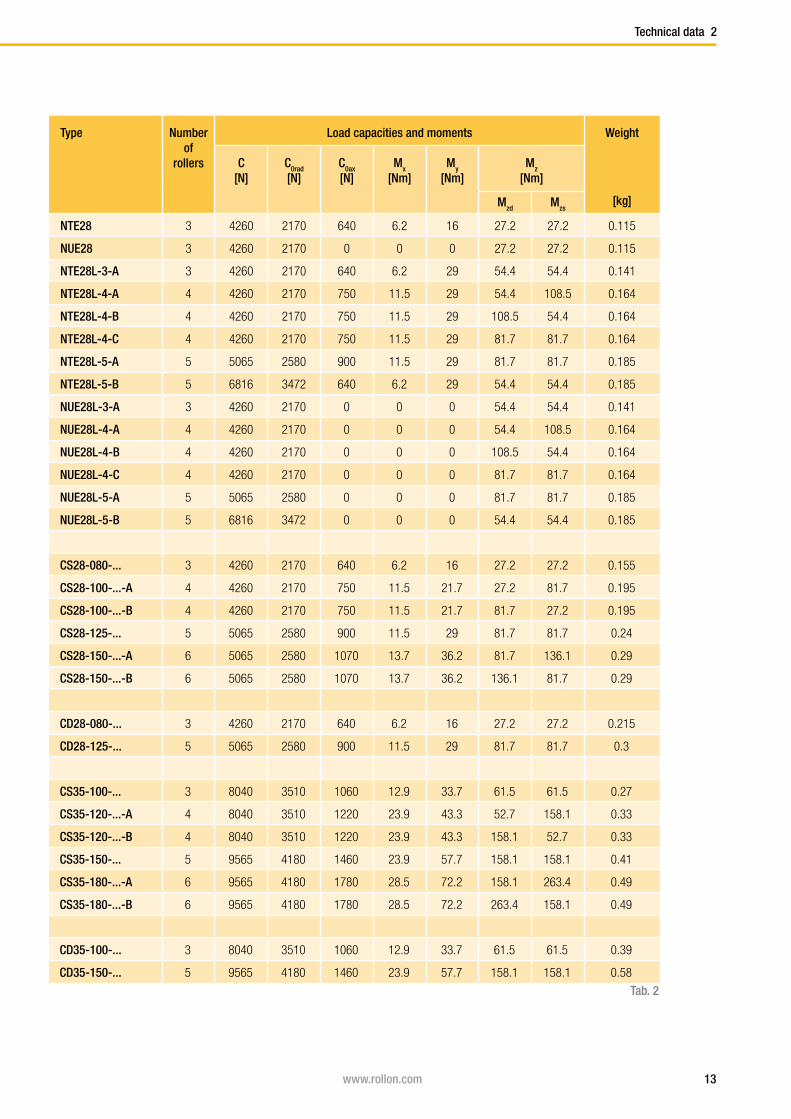
Technical data 2
Type Number of
rollers
Load capacities and moments Weight
[kg]
C[N]
C0rad
[N]C0ax
[N]Mx
[Nm]My
[Nm]Mz
[Nm]
Mzd Mzs
NTE28 3 4260 2170 640 6.2 16 27.2 27.2 0.115
NUE28 3 4260 2170 0 0 0 27.2 27.2 0.115
NTE28L-3-A 3 4260 2170 640 6.2 29 54.4 54.4 0.141
NTE28L-4-A 4 4260 2170 750 11.5 29 54.4 108.5 0.164
NTE28L-4-B 4 4260 2170 750 11.5 29 108.5 54.4 0.164
NTE28L-4-C 4 4260 2170 750 11.5 29 81.7 81.7 0.164
NTE28L-5-A 5 5065 2580 900 11.5 29 81.7 81.7 0.185
NTE28L-5-B 5 6816 3472 640 6.2 29 54.4 54.4 0.185
NUE28L-3-A 3 4260 2170 0 0 0 54.4 54.4 0.141
NUE28L-4-A 4 4260 2170 0 0 0 54.4 108.5 0.164
NUE28L-4-B 4 4260 2170 0 0 0 108.5 54.4 0.164
NUE28L-4-C 4 4260 2170 0 0 0 81.7 81.7 0.164
NUE28L-5-A 5 5065 2580 0 0 0 81.7 81.7 0.185
NUE28L-5-B 5 6816 3472 0 0 0 54.4 54.4 0.185
CS28-080-... 3 4260 2170 640 6.2 16 27.2 27.2 0.155
CS28-100-...-A 4 4260 2170 750 11.5 21.7 27.2 81.7 0.195
CS28-100-...-B 4 4260 2170 750 11.5 21.7 81.7 27.2 0.195
CS28-125-... 5 5065 2580 900 11.5 29 81.7 81.7 0.24
CS28-150-...-A 6 5065 2580 1070 13.7 36.2 81.7 136.1 0.29
CS28-150-...-B 6 5065 2580 1070 13.7 36.2 136.1 81.7 0.29
CD28-080-... 3 4260 2170 640 6.2 16 27.2 27.2 0.215
CD28-125-... 5 5065 2580 900 11.5 29 81.7 81.7 0.3
CS35-100-... 3 8040 3510 1060 12.9 33.7 61.5 61.5 0.27
CS35-120-...-A 4 8040 3510 1220 23.9 43.3 52.7 158.1 0.33
CS35-120-...-B 4 8040 3510 1220 23.9 43.3 158.1 52.7 0.33
CS35-150-... 5 9565 4180 1460 23.9 57.7 158.1 158.1 0.41
CS35-180-...-A 6 9565 4180 1780 28.5 72.2 158.1 263.4 0.49
CS35-180-...-B 6 9565 4180 1780 28.5 72.2 263.4 158.1 0.49
CD35-100-... 3 8040 3510 1060 12.9 33.7 61.5 61.5 0.39
CD35-150-... 5 9565 4180 1460 23.9 57.7 158.1 158.1 0.58
Tab. 2

14 www.rollon.com
2 Technical data
Type Number of
rollers
Load capacities and moments Weight
[kg]
C[N]
C0rad
[N]C0ax
[N]Mx
[Nm]My
[Nm]Mz
[Nm]
Mzd Mzs
NTE43 3 12280 5500 1570 23.6 60 104.5 104.5 0.385
NUE43 3 12280 5500 0 0 0 104.5 104.5 0.385
NKE43 3 12280 5100 1320 0 50.4 96.9 96.9 0.385
NTE43L-3-A 3 12280 5500 1570 23.6 108.6 209 209 0.45
NTE43L-4-A 4 12280 5500 1855 43.6 108.6 209 418 0.52
NTE43L-4-B 4 12280 5500 1855 43.6 108.6 418 209 0.52
NTE43L-4-C 4 12280 5500 1855 43.6 108.6 313.5 313.5 0.52
NTE43L-5-A 5 14675 6540 2215 43.6 108.6 313.5 313.5 0.59
NTE43L-5-B 5 19650 8800 1570 23.6 108.6 209 209 0.59
NUE43L-3-A 3 12280 5500 0 0 0 209 209 0.45
NUE43L-4-A 4 12280 5500 0 0 0 209 418 0.52
NUE43L-4-B 4 12280 5500 0 0 0 418 209 0.52
NUE43L-4-C 4 12280 5500 0 0 0 313.5 313.5 0.52
NUE43L-5-A 5 14675 6540 0 0 0 313.5 313.5 0,59
NUE43L-5-B 5 19650 8800 0 0 0 209 209 0.59
NKE43L-3-A 3 12280 5100 1320 0 97.7 188.7 188.7 0.45
NKE43L-4-A 4 12280 5100 1320 0 97.7 188.7 377.3 0.52
NKE43L-4-B 4 12280 5100 1320 0 97.7 377.3 188.7 0.52
NKE43L-4-C 4 12280 5100 1320 0 97.7 283 283 0.52
NKE43L-5-A 5 14675 6065 1570 0 97.7 283 283 0.59
NKE43L-5-B 5 19650 8160 1820 0 97.7 188.7 188.7 0.59
CS43-120-... 3 12280 5500 1570 23.6 60 104.5 104.5 0.53
CS43-150-...-A 4 12280 5500 1855 43.6 81.5 104.5 313.5 0.68
CS43-150-...-B 4 12280 5500 1855 43.6 81.5 313.5 104.5 0.68
CS43-190-... 5 14675 6540 2215 43.6 108.6 313.5 313.5 0.84
CS43-230-...-A 6 14675 6540 2645 52 135.8 313.5 522.5 1.01
CS43-230-...-B 6 14675 6540 2645 52 135.8 522.5 313.5 1.01
Tab. 3

15www.rollon.com
Technical data 2
Type Number of
rollers
Load capacities and moments Weight
[kg]
C[N]
C0rad
[N]C0ax
[N]Mx
[Nm]My
[Nm]Mz
[Nm]
Mzd Mzs
CSK43-120-... 3 12280 5100 1320 0 50.4 96.9 96.9 0.53
CSK43-150-A 4 12280 5100 1320 0 54.3 96.9 290.7 0.68
CSK43-150-B 4 12280 5100 1320 0 54.3 290.7 96.9 0.68
CSK43-190-... 5 14675 6065 1570 0 108.7 290.7 290.7 0.84
CSK43-230-A 6 14675 6065 1570 0 108.7 290.7 484.5 1.01
CSK43-230-B 6 14675 6065 1570 0 108.7 484.5 290.7 1.01
CD43-120-... 3 12280 5500 1570 23.6 60 104.5 104.5 0.64
CD43-190-... 5 14675 6540 2215 43.6 108.6 313.5 313.5 0.95
CDK43-120-... 3 12280 5100 1320 0 50.4 96.9 96.9 0.64
CDK43-190-... 5 14675 6065 1570 0 108.7 290.7 290.7 0.95
NTE63 3 30750 12500 6000 125 271 367 367 1.07
NUE63 3 30750 12500 0 0 0 367 367 1.07
NKE63 3 30750 11550 5045 0 235 335 335 1.07
CS63-180-2ZR 3 30750 12500 6000 125 271 367 367 1.66
CS63-235-2ZR-A 4 30750 12500 7200 250 413 367 1100 2.17
CS63-235-2ZR-B 4 30750 12500 7200 250 413 1100 367 2.17
CS63-290-2ZR 5 36600 15000 8500 250 511 1100 1100 2.67
CS63-345-2ZR-A 6 36600 15000 10000 350 689 1100 1830 3.17
CS63-345-2ZR-B 6 36600 15000 10000 350 689 1830 1100 3.17
CSK63-180-2ZR 3 30750 11550 5045 0 235 335 335 1.66
CSK63-235-2ZR-A 4 30750 11550 5045 0 294 335 935 2.17
CSK63-235-2ZR-B 4 30750 11550 5045 0 294 935 335 2.17
CSK63-290-2ZR 5 36600 13745 6000 0 589 935 935 2.67
CSK63-345-2ZR-A 6 36600 13745 6000 0 589 935 1560 3.17
CSK63-345-2ZR-B 6 36600 13745 6000 0 589 1560 935 3.17
Tab. 4
16 www.rollon.com
B
T
A
E2
T-63
B
A
T
E2
K-63
B
T
A
E2
U-63
B
T
A
E1
U-43
B
T
A
E1
T-43
B
A
TE
K-43
1
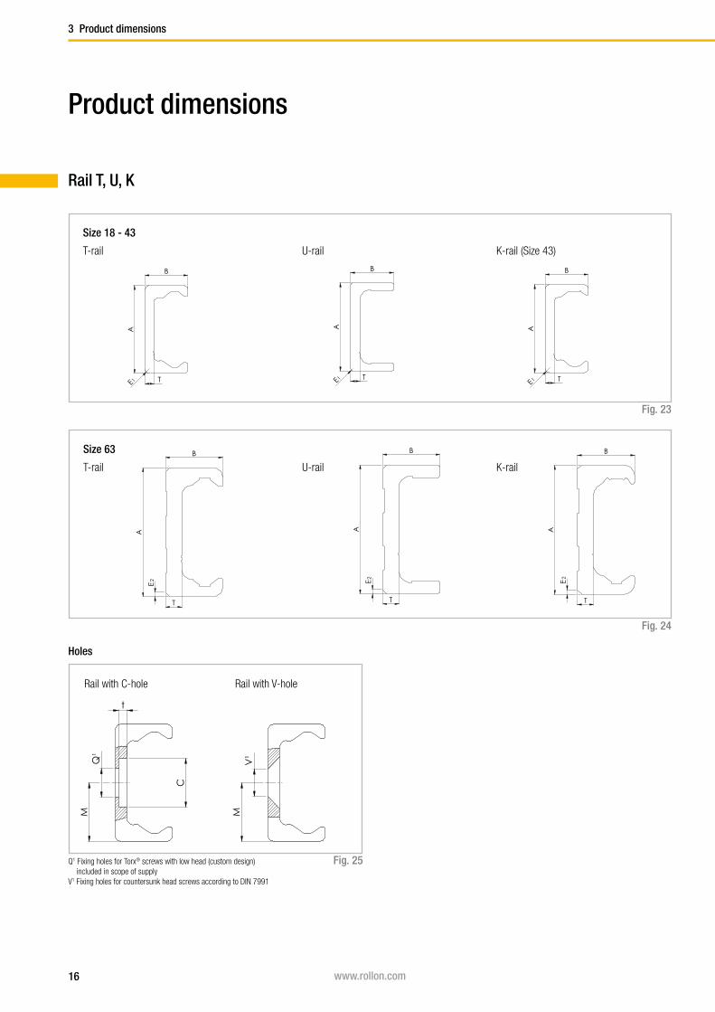
Product dimensions
3 Product dimensions
Rail T, U, K
T-rail U-rail K-rail (Size 43)
Size 18 - 43
Fig. 23
T-rail U-rail K-rail
Q1 Fixing holes for Torx® screws with low head (custom design) included in scope of supply
V1 Fixing holes for countersunk head screws according to DIN 7991
Size 63
Fig. 24
Holes
Fig. 25
Rail with C-hole Rail with V-hole
C
Q¹
t
M MV
¹
C
Q¹
t
M MV
¹
17www.rollon.com
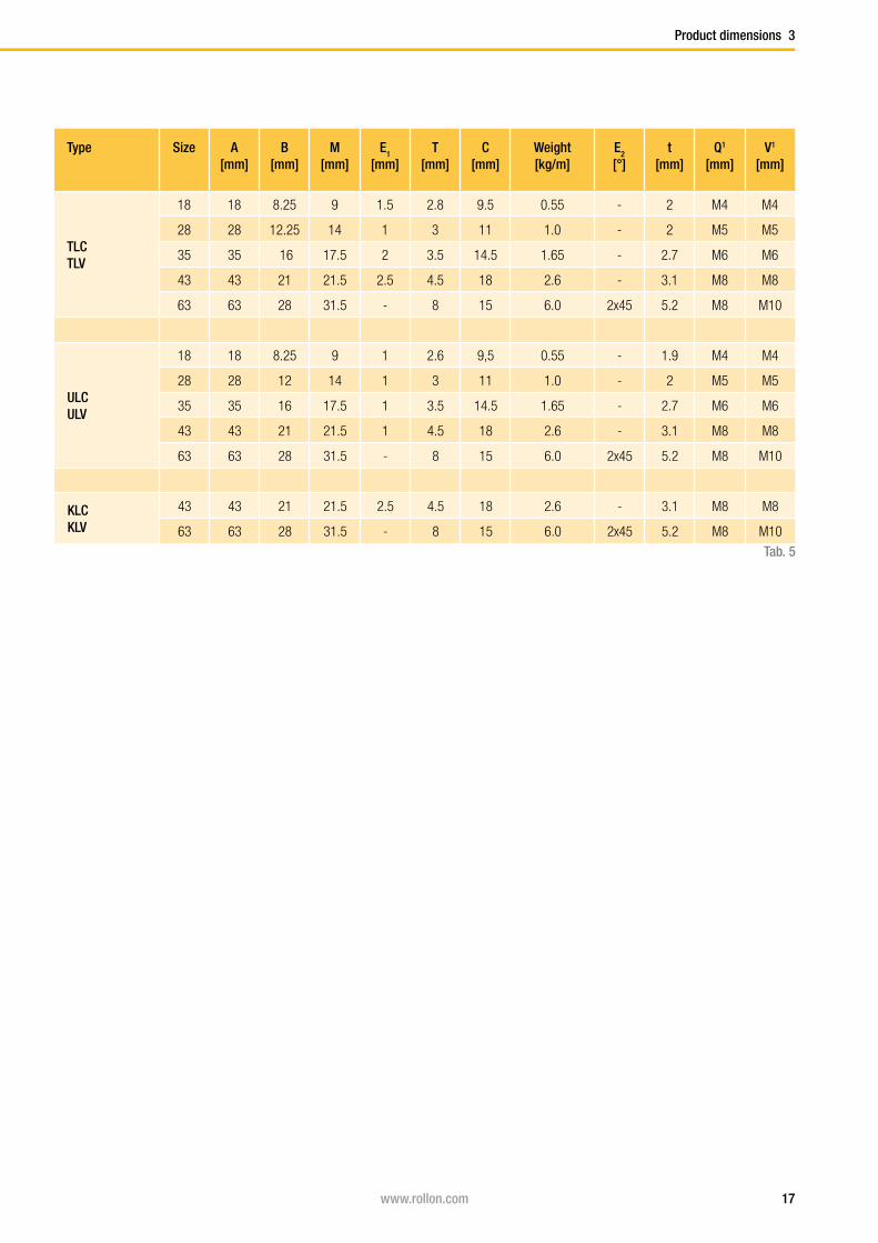
Product dimensions 3
Type Size A[mm]
B[mm]
M[mm]
E1
[mm]T
[mm]C
[mm]Weight [kg/m]
E2
[°]t
[mm]Q1
[mm]V1
[mm]
TLCTLV
18 18 8.25 9 1.5 2.8 9.5 0.55 - 2 M4 M4
28 28 12.25 14 1 3 11 1.0 - 2 M5 M5
35 35 16 17.5 2 3.5 14.5 1.65 - 2.7 M6 M6
43 43 21 21.5 2.5 4.5 18 2.6 - 3.1 M8 M8
63 63 28 31.5 - 8 15 6.0 2x45 5.2 M8 M10
ULCULV
18 18 8.25 9 1 2.6 9,5 0.55 - 1.9 M4 M4
28 28 12 14 1 3 11 1.0 - 2 M5 M5
35 35 16 17.5 1 3.5 14.5 1.65 - 2.7 M6 M6
43 43 21 21.5 1 4.5 18 2.6 - 3.1 M8 M8
63 63 28 31.5 - 8 15 6.0 2x45 5.2 M8 M10
KLCKLV
43 43 21 21.5 2.5 4.5 18 2.6 - 3.1 M8 M8
63 63 28 31.5 - 8 15 6.0 2x45 5.2 M8 M10
Tab. 5
18 www.rollon.com
B
T
A
E2
T-63
C
Q¹
t
M MV
¹
B
T
A
E1
T-43
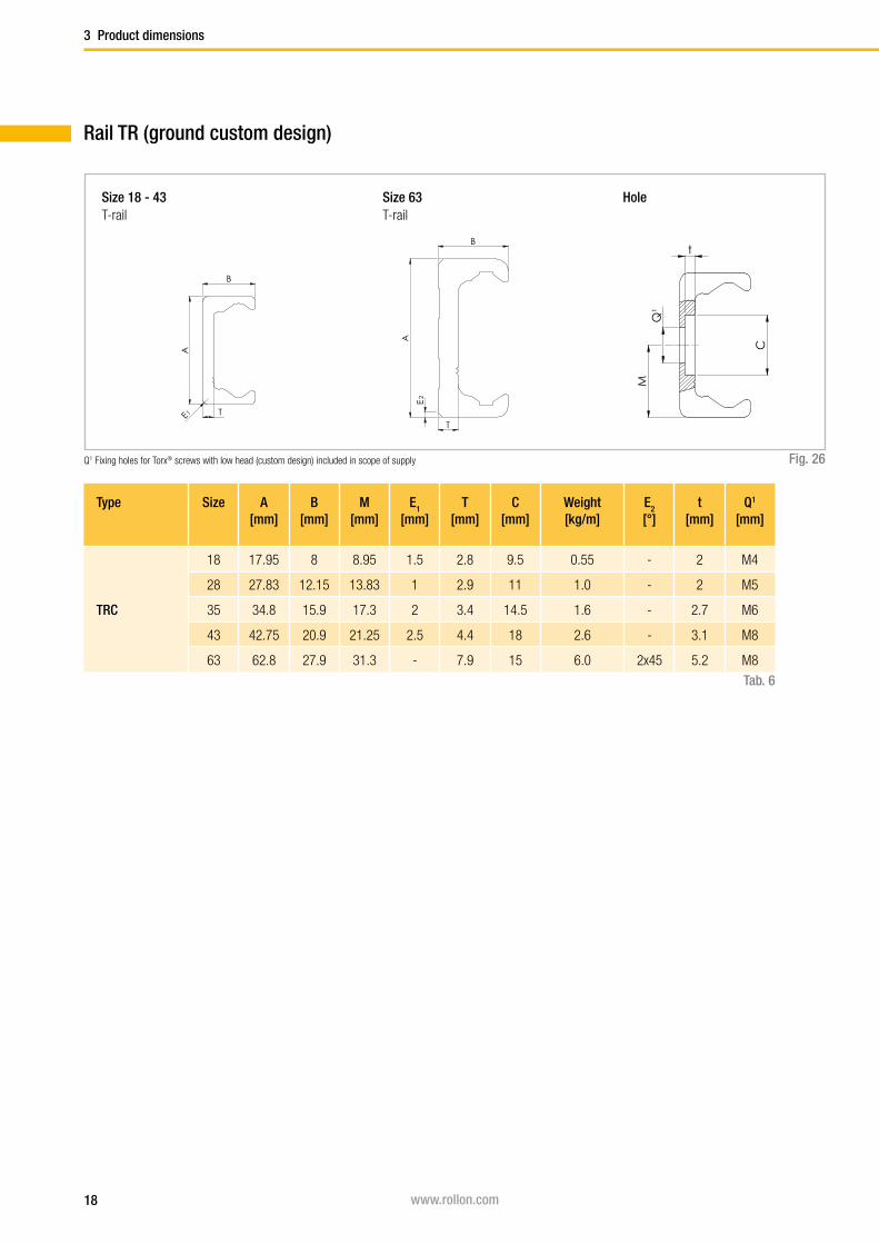
3 Product dimensions
Fig. 26
Type Size A[mm]
B[mm]
M[mm]
E1
[mm]T
[mm]C
[mm]Weight [kg/m]
E2
[°]t
[mm]Q1
[mm]
TRC
18 17.95 8 8.95 1.5 2.8 9.5 0.55 - 2 M4
28 27.83 12.15 13.83 1 2.9 11 1.0 - 2 M5
35 34.8 15.9 17.3 2 3.4 14.5 1.6 - 2.7 M6
43 42.75 20.9 21.25 2.5 4.4 18 2.6 - 3.1 M8
63 62.8 27.9 31.3 - 7.9 15 6.0 2x45 5.2 M8
Tab. 6
Rail TR (ground custom design)
T-railSize 18 - 43
T-railSize 63 Hole
Q1 Fixing holes for Torx® screws with low head (custom design) included in scope of supply

19www.rollon.com
40 -2+1
80 40
L
Reference line
+ 2 - 4
0,2
Product dimensions 3
Fig. 27
Rail length
Tab. 7
Type Size Min length
[mm]
Max length
[mm]
Available standard lengths L
[mm]
TLC TLV ULC ULV
18 160 2000
160 - 240 - 320 - 400 - 480 - 560 - 640 - 720 - 800 - 880
- 960 - 1040 - 1120 - 1200 - 1280 - 1360 - 1440
- 1520 - 1600 - 1680 - 1760 - 1840 - 1920 - 2000 - 2080
- 2160 - 2240 - 2320 - 2400 - 2480 - 2560 - 2640
- 2720 - 2800 - 2880 - 2960 - 3040 - 3120 - 3200 - 3280
- 3360 - 3440 - 3520 - 3600
28 240 3200
35 320 3600
43 400 3600
63 560 3600
KLC KLV
43 400 3600
63 560 3600
TRC
18 160 2000
28 240 2000
35 320 2000
43 400 2000
63 560 2000
Longer single rails up to max. 4,080 mm on requestLonger rail systems see pg. 68ff Joined rails
20 www.rollon.com
X
A
B
X
Y
1
F
G
C
G
F C
G
F C
X
A
B
Y
C
F
G
C
F
G
C
F
G
NTE28/43 NUE28/43 NKE43
X
A
B
Y G
C
F F
C
G
NT18 NU18
3 Product dimensions
N-version slider, normal
N-series
Fig. 28
Size 18
Fig. 29
Sizes 28 and 43 (not available in size 35)
Fig. 30
Size 63
Slider NT Slider NU
Slider NTE Slider NUE Slider NKE
Size 43
Slider NTE Slider NUE Slider NKE
21www.rollon.com
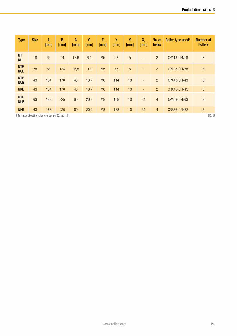
Product dimensions 3
Type Size A[mm]
B[mm]
C[mm]
G[mm]
F[mm]
X[mm]
Y[mm]
X1
[mm]No. ofholes
Roller type used* Number of Rollers
NTNU
18 62 74 17.6 6.4 M5 52 5 - 2 CPA18-CPN18 3
NTENUE
28 88 124 26,5 9.3 M5 78 5 - 2 CPA28-CPN28 3
NTENUE
43 134 170 40 13.7 M8 114 10 - 2 CPA43-CPN43 3
NKE 43 134 170 40 13.7 M8 114 10 - 2 CRA43-CRN43 3
NTENUE
63 188 225 60 20.2 M8 168 10 34 4 CPA63-CPN63 3
NKE 63 188 225 60 20.2 M8 168 10 34 4 CRA63-CRN63 3
Tab. 8* Information about the roller type, see pg. 32, tab. 18

22 www.rollon.com
B
A
Y X Z X
F
C
G
F
C
G
F
C
G
3 Product dimensions
N...L-series
Fig. 31
Sizes 28 and 43
Slider configurations N...L
Fig. 32
N-version slider, long
Slider NTE Slider NUE Slider NKE
Size 43
N...L-3-A
N...L-4-A
N...L-4-B
N...L-4-C
N...L-5-A
N...L-5-B

23www.rollon.com
Product dimensions 3
Type Size A[mm]
B[mm]
C[mm]
G[mm]
F[mm]
X[mm]
Y[mm]
Z[mm]
No. of holes
Roller type used*
Number**of Rollers
NTE28L NUE28L
28 140 176 26.5 9 M5 52 5 26 4 CPA283 45
NTE43LNUE43L 43 208 245 41 13.7 M8 75.5 10 37 4
CPA43 345NKE43L CRA43
Tab. 9* Information about the roller type, see pg. 32, tab. 18** The number of roller varies according to the configuration, see pg. 22, fig. 32
24 www.rollon.com
F
C
G
C
F
G
T- und U-Schiene K-Schiene
BA
Y X X
BA
Y X X
BA
Y X X X
BA
Y X
BA
Y X
BA
Y X
3 Product dimensions
CS-series
Fig. 33
Fig. 34
C-version slider
CS-slider with prismatic rollers for use in T- and U-rails
Representation of slider with wiper
CSK-slider with crowned rollers for use in K-railsSizes 43 and 63
Configuration A Configuration A
Configuration B Configuration B

25www.rollon.com
Product dimensions 3
Type Size A[mm]
B[mm]
C[mm]
G[mm]
F[mm]
X[mm]
Y[mm]
No. of holes
Roller type used*
Number of Rollers
CS
18
60 76 9.5 5.7 M5 20 20 2 CPA18-CPN18 3
80 96 9.5 5.7 M5 40 20 2 CPA18 4
100 116 9.5 5.7 M5 20 20 4 CPA18 5
120 136 9.5 5.7 M5 40 20 3 CPA18 6
28
80 100 14.9 9.7 M5 35 22.5 2 CPA28-CPN28 3
100 120 14.9 9.7 M5 50 25 2 CPA28 4
125 145 14.9 9.7 M5 25 25 4 CPA28 5
150 170 14.9 9.7 M5 50 25 3 CPA28 6
35
100 120 19.9 11.9 M6 45 27.5 2 CPA35-CPN35 3
120 140 19.9 11.9 M6 60 30 2 CPA35 4
150 170 19.9 11.9 M6 30 30 4 CPA35 5
180 200 19.9 11.9 M6 60 30 3 CPA35 6
43
120 140 24.9 14.5 M8 55 32.5 2 CPA43-CPN43 3
150 170 24.9 14.5 M8 80 35 2 CPA43 4
190 210 24.9 14.5 M8 40 35 4 CPA43 5
230 250 24.9 14.5 M8 80 35 3 CPA43 6
63
180 200 39.5 19.5 M8 54 9 4 CPA63 3
235 255 39.5 19.5 M8 54 9.5 5 CPA63 4
290 310 39.5 19.5 M8 54 10 6 CPA63 5
345 365 39.5 19.5 M8 54 10.5 7 CPA63 6
CSK
43
120 140 24.9 14.5 M8 55 32.5 2 CRA43-CRN43 3
150 170 24.9 14.5 M8 80 35 2 CRA43 4
190 210 24.9 14.5 M8 40 35 4 CRA43 5
230 250 24.9 14.5 M8 80 35 3 CRA43 6
63
180 200 39.5 19.5 M8 54 9 4 CRA63 3
235 255 39.5 19.5 M8 54 9.5 5 CRA63 4
290 310 39.5 19.5 M8 54 10 6 CRA63 5
345 365 39.5 19.5 M8 54 10.5 7 CRA63 6
Tab. 10* Information about the roller type, see pg. 32, tab. 18
26 www.rollon.com
AB
Y X X X
AB
Y X X X
AB
Y X
AB
Y X
T
C
G
F
MHole S for screw according to DIN 912
T
C
F
G
MHole S for screw according to DIN 912
CD-Läufer CDR-Läufer
T
C
G
F
MHole S for screw according to DIN 912
T
C
F
G
MHole S for screw according to DIN 912
CD-Läufer CDR-Läufer
3 Product dimensions
CD-series
Fig. 35
Type Size A[mm]
B[mm]
C[mm]
T[mm]
M[mm]
S G[mm]
F X[mm]
Y[mm]
No. of holes
Roller type used*
Number of Rollers
CD
2880 100 29.9 9.9 4.9 M5 15 M6 36 22 2 CPA28 3
125 145 29.9 9.9 4.9 M5 15 M6 27 22 4 CPA28 5
35100 120 34.9 11.8 5.9 M6 15 M8 45 27.5 2 CPA35 3
150 170 34.9 11.8 5.9 M6 15 M8 30 30 4 CPA35 5
43120 140 44.9 14.8 7.3 M6 15 M8 56 32 2 CPA43 3
190 210 44.9 14.8 7.3 M6 15 M8 42 32 4 CPA43 5
CDK 43120 140 44.9 14.8 7.3 M6 15 M8 56 32 2 CRA43 3
190 210 44.9 14.8 7.3 M6 15 M8 42 32 4 CRA43 5
Tab. 11
Configuration A Configuration A
Configuration B Configuration B
Representation of slider with wiper
Fig. 36
* Information about the roller type, see pg. 32, tab. 18
CD-slider with beveled rollers for use in T- and U-rails
CDK-slider with crowned rollers for use in K-railsSize 43
27www.rollon.com
A
C D
BReference line
A C
D
BReference line
A C D
BReference line
Product dimensions 3
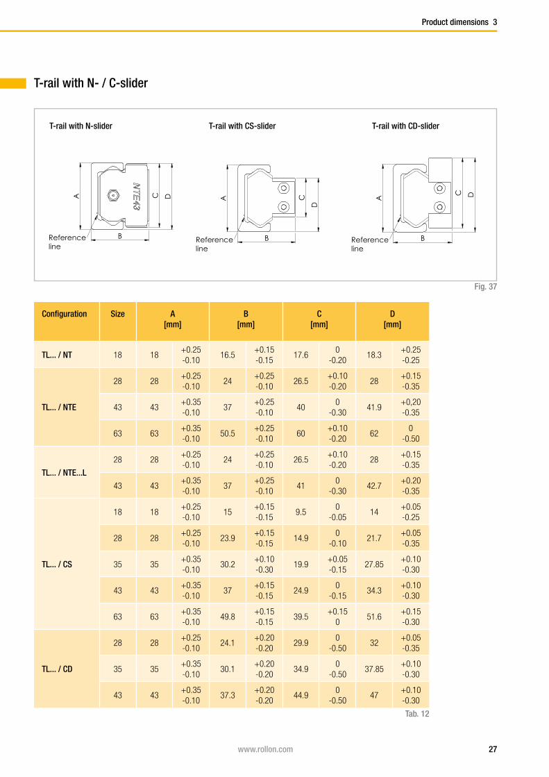
T-rail with N- / C-slider
T-rail with CS-sliderT-rail with N-slider
Fig. 37
Configuration Size A[mm]
B[mm]
C[mm]
D[mm]
TL... / NT 18 18+0.25 -0.10
16.5+0.15 -0.15
17.60
-0.2018.3
+0.25 -0.25
TL... / NTE
28 28+0.25 -0.10
24+0.25 -0.10
26.5+0.10-0.20
28+0.15 -0.35
43 43+0.35 -0.10
37+0.25 -0.10
400
-0.3041.9
+0,20 -0.35
63 63+0.35 -0.10
50.5+0.25 -0.10
60+0.10-0.20
620
-0.50
TL... / NTE...L
28 28+0.25-0.10
24+0.25-0.10
26.5+0.10-0.20
28+0.15-0.35
43 43+0.35-0.10
37+0.25-0.10
410
-0.3042.7
+0.20-0.35
TL... / CS
18 18+0.25 -0.10
15+0.15 -0.15
9.50
-0.0514
+0.05 -0.25
28 28+0.25 -0.10
23.9+0.15 -0.15
14.90
-0.1021.7
+0.05 -0.35
35 35+0.35-0.10
30.2+0.10-0.30
19.9+0.05-0.15
27.85+0.10-0.30
43 43+0.35 -0.10
37+0.15 -0.15
24.90
-0.1534.3
+0.10 -0.30
63 63+0.35 -0.10
49.8+0.15 -0.15
39.5+0.15
051.6
+0.15 -0.30
TL... / CD
28 28+0.25 -0.10
24.1+0.20 -0.20
29.90
-0.5032
+0.05 -0.35
35 35+0.35-0.10
30.1+0.20-0.20
34.90
-0.5037.85
+0.10-0.30
43 43+0.35 -0.10
37.3+0.20 -0.20
44.90
-0.5047
+0.10 -0.30
Tab. 12
T-rail with CD-slider
28 www.rollon.com
A C D
BReference line
A
C D
BReference line
A C
D
BReference line
3 Product dimensions
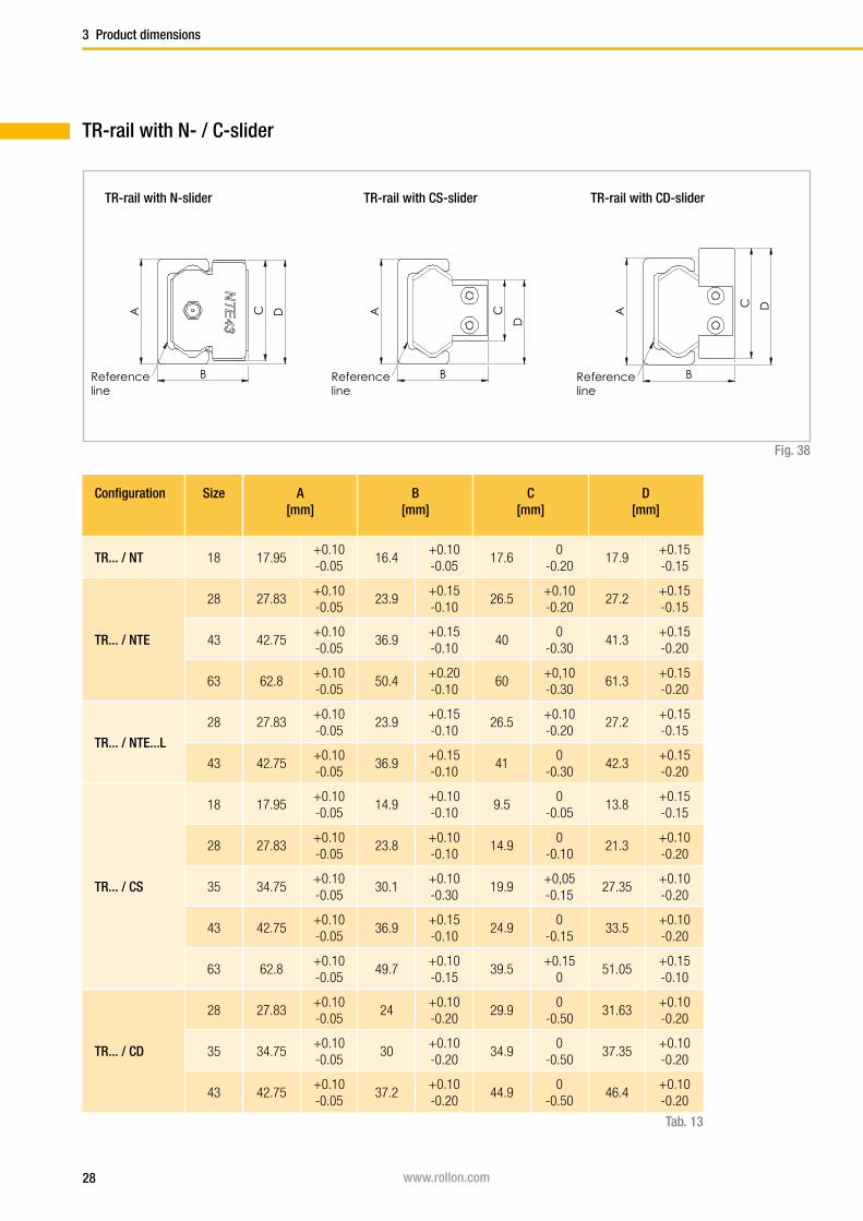
TR-rail with N- / C-slider
TR-rail with N-slider
Fig. 38
Configuration Size A[mm]
B[mm]
C[mm]
D[mm]
TR... / NT 18 17.95+0.10-0.05
16.4+0.10-0.05
17.60
-0.2017.9
+0.15-0.15
TR... / NTE
28 27.83+0.10-0.05
23.9+0.15-0.10
26.5+0.10-0.20
27.2+0.15-0.15
43 42.75+0.10-0.05
36.9+0.15-0.10
400
-0.3041.3
+0.15-0.20
63 62.8+0.10-0.05
50.4+0.20-0.10
60+0,10-0.30
61.3+0.15-0.20
TR... / NTE...L
28 27.83+0.10-0.05
23.9+0.15-0.10
26.5+0.10-0.20
27.2+0.15-0.15
43 42.75+0.10-0.05
36.9+0.15-0.10
410
-0.3042.3
+0.15-0.20
TR... / CS
18 17.95+0.10-0.05
14.9+0.10-0.10
9.50
-0.0513.8
+0.15-0.15
28 27.83+0.10-0.05
23.8+0.10-0.10
14.90
-0.1021.3
+0.10-0.20
35 34.75+0.10-0.05
30.1+0.10-0.30
19.9+0,05-0.15
27.35+0.10-0.20
43 42.75+0.10-0.05
36.9+0.15-0.10
24.90
-0.1533.5
+0.10-0.20
63 62.8+0.10-0.05
49.7+0.10-0.15
39.5+0.15
051.05
+0.15-0.10
TR... / CD
28 27.83+0.10-0.05
24+0.10-0.20
29.90
-0.5031.63
+0.10-0.20
35 34.75+0.10-0.05
30+0.10-0.20
34.90
-0.5037.35
+0.10-0.20
43 42.75+0.10-0.05
37.2+0.10-0.20
44.90
-0.5046.4
+0.10-0.20
Tab. 13
TR-rail with CS-slider TR-rail with CD-slider
29www.rollon.com
A C D
BReference line
A C
D
BReference line
A
C D
BReference line
Product dimensions 3
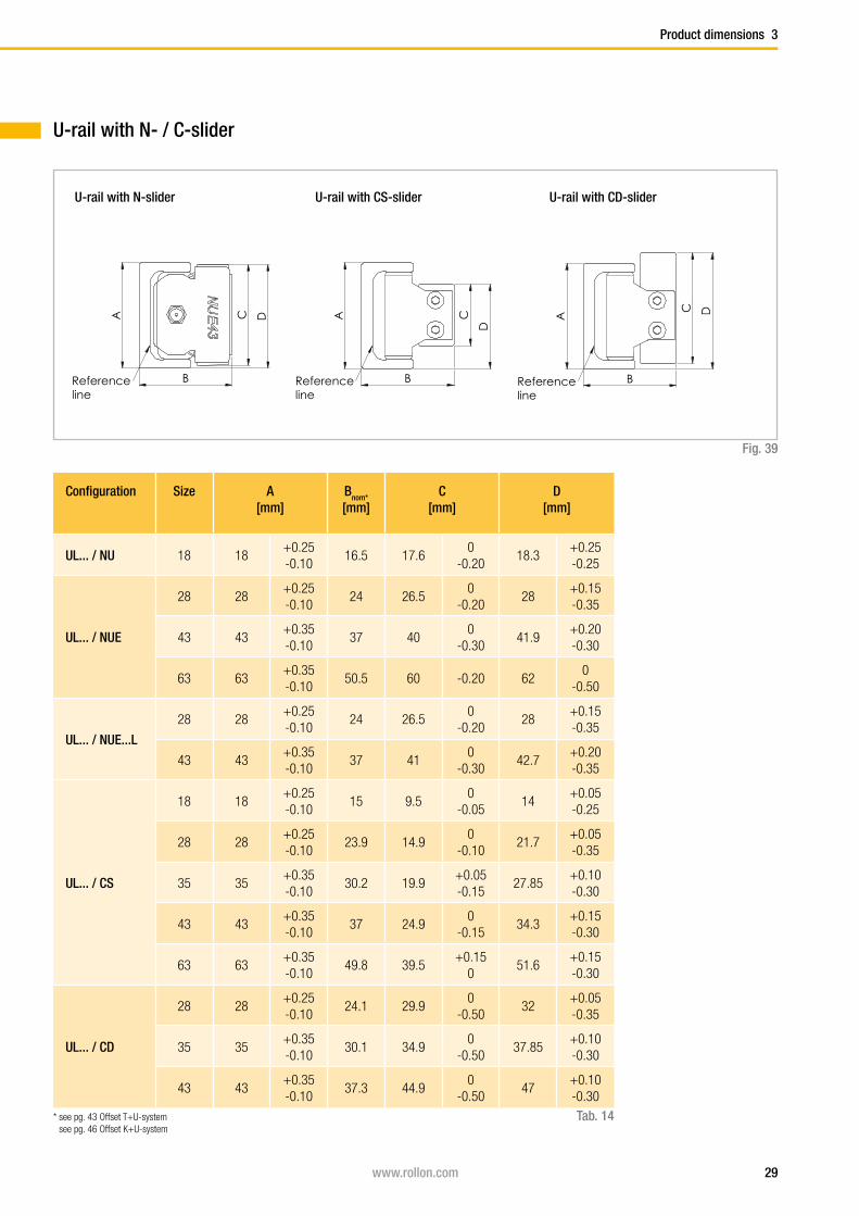
U-rail with N- / C-slider
U-rail with N-slider
Fig. 39
Configuration Size A[mm]
Bnom*
[mm]C
[mm]D
[mm]
UL... / NU 18 18+0.25 -0.10
16.5 17.60
-0.2018.3
+0.25 -0.25
UL... / NUE
28 28+0.25 -0.10
24 26.50
-0.2028
+0.15 -0.35
43 43+0.35 -0.10
37 400
-0.3041.9
+0.20 -0.30
63 63+0.35 -0.10
50.5 60 -0.20 620
-0.50
UL... / NUE...L
28 28+0.25-0.10
24 26.50
-0.2028
+0.15-0.35
43 43+0.35-0.10
37 410
-0.3042.7
+0.20-0.35
UL... / CS
18 18+0.25 -0.10
15 9.50
-0.0514
+0.05 -0.25
28 28+0.25 -0.10
23.9 14.90
-0.1021.7
+0.05 -0.35
35 35+0.35-0.10
30.2 19.9+0.05-0.15
27.85+0.10-0.30
43 43+0.35 -0.10
37 24.90
-0.1534.3
+0.15 -0.30
63 63+0.35 -0.10
49.8 39.5+0.15
051.6
+0.15 -0.30
UL... / CD
28 28+0.25 -0.10
24.1 29.90
-0.5032
+0.05 -0.35
35 35+0.35-0.10
30.1 34.90
-0.5037.85
+0.10-0.30
43 43+0.35 -0.10
37.3 44.90
-0.5047
+0.10 -0.30
U-rail with CS-slider U-rail with CD-slider
Tab. 14* see pg. 43 Offset T+U-system see pg. 46 Offset K+U-system
30 www.rollon.com
A
B
C D
Reference line
AB
C
D
Reference line
A
B
C D
Reference line
3 Product dimensions
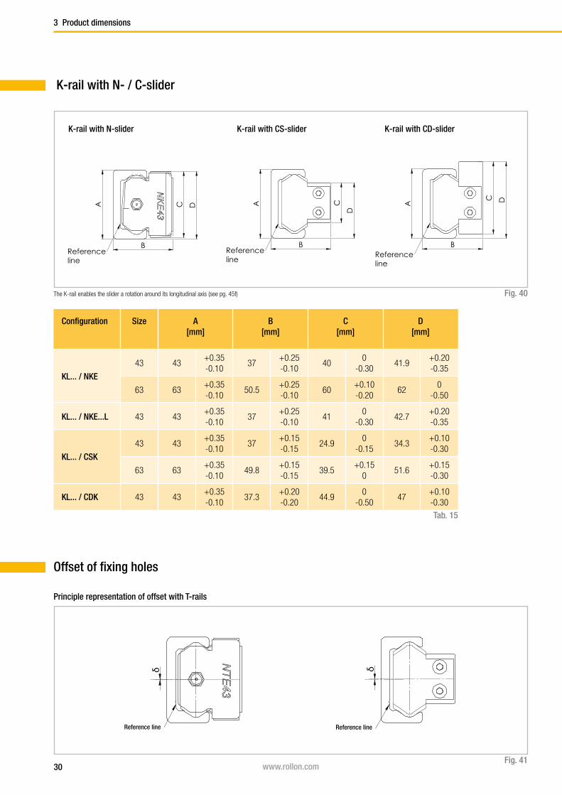
K-rail with N- / C-slider
K-rail with N-slider
Fig. 40
Configuration Size A[mm]
B[mm]
C[mm]
D[mm]
KL... / NKE
43 43+0.35 -0.10
37+0.25-0.10
400
-0.3041.9
+0.20 -0.35
63 63+0.35 -0.10
50.5+0.25-0.10
60+0.10-0.20
620
-0.50
KL... / NKE...L 43 43+0.35-0.10
37+0.25-0.10
410
-0.3042.7
+0.20-0.35
KL... / CSK
43 43+0.35 -0.10
37+0.15-0.15
24.90
-0.1534.3
+0.10-0.30
63 63+0.35 -0.10
49.8+0.15-0.15
39.5+0.15
051.6
+0.15-0.30
KL... / CDK 43 43+0.35 -0.10
37.3+0.20-0.20
44.90
-0.5047
+0.10-0.30
Tab. 15
The K-rail enables the slider a rotation around its longitudinal axis (see pg. 45f)
K-rail with CS-slider K-rail with CD-slider
Offset of fixing holes
Bezugslinie
δ
Bezugslinie
δ
Fig. 41
Reference lineReference line
Principle representation of offset with T-rails

31www.rollon.com
Product dimensions 3
Configura-tion
Size δ nominal[mm]
δ maximum[mm]
δ minimum[mm]
TLC / NT 18 0.45 0.95 -0.25
TLC / NTE
28 0.35 0.85 -0.4
43 0.35 0.9 -0.5
63 0.35 0.8 -0.55
KLC / NKE43 0.35 0.9 -0.5
63 0.35 0.8 -0.55
ULC / NU 18 0.4 0.9 -0.25
ULC / NUE
28 0.4 0.85 -0.3
43 0.4 0.85 -0.45
63 0.35 0.8 -0.45
TLV / NT 18 0.45 0.8 -0.2
TLV / NTE
28 0.35 0.7 -0.35
43 0.35 0.75 -0.45
63 0.35 0.65 -0.55
KLV / NKE43 0.35 0.75 -0.45
63 0.35 0.65 -0.55
ULV / NU 18 0.4 0.75 -0.2
ULV / NUE
28 0.4 0.7 -0.25
43 0.4 0.7 -0.4
63 0.35 0.65 -0.45
TLC / CS
18 0.35 0.75 -0.2
28 0.25 0.6 -0.35
35 0.35 0.7 -0.35
43 0.35 0.8 -0.35
63 0.35 0.6 -0.35
KLC / CSK43 0.35 0.8 -0.35
63 0.35 0.6 -0.35
Configura-tion
Size δ nominal[mm]
δ maximum[mm]
δ minimum[mm]
ULC / CS
18 0.3 0.7 -0.2
28 0.3 0.6 -0.3
35 0.35 0.7 -0.35
43 0.4 0.75 -0.35
63 0.35 0.6 -0.25
TLV / CS
18 0.35 0.6 -0.15
28 0.25 0.45 -0.3
35 0.35 0.55 -0.3
43 0.35 0.65 -0.3
63 0.35 0.45 -0.35
KLV / CSK43 0.35 0.65 -0.3
63 0.35 0.45 -0.35
ULV / CS
18 0.3 0.55 -0.15
28 0.3 0.45 -0.25
35 0.35 0.55 -0.3
43 0.4 0.6 -0.3
63 0.35 0.45 -0.25
TRC / NT 18 0.15 0.65 -0.2
TRC / NTE
28 0.15 -0.5 -0.25
43 0.05 0.4 -0.3
63 0 0.4 -0.4
TRC / CS
18 0.05 0.45 -0.2
28 0.05 0.3 -0.25
35 0.1 0.35 -0.2
43 0.05 0.35 -0.25
63 0 0.2 -0.2
Tab. 16
Tab. 17

32 www.rollon.com
A D
KHB
G
F
Ecc
en
tric
ity
A D
BH K
F
Ecc
en
tric
ity
G
CPN/CPA CRN/CRA
A DKH
B
G
F
Ecc
en
tric
ity
A D
BH K
F
Ecc
en
tric
ity
G
CPN/CPA CRN/CRA
Accessories
4 Accessories
Rollers
Version 1
Prismatic (T- and U-rail)
Type A[mm]
B[mm]
D[mm]
e[mm]
H [mm]
K[mm]
G[mm]
F C[N]
C0rad
[N]Weight
[kg]
CPN18-2RS 14 4 6 - 1.55 1.8 5.5 M4 765 410 0.004
CPN18-2Z 14 4 6 - 1.55 1.8 5.5 M4 765 410 0.004
CPA18-2RS 14 4 6 0.4 1.55 1.8 5.5 M4 765 410 0.004
CPA18-2Z 14 4 6 0.4 1.55 1.8 5.5 M4 765 410 0.004
CPN28-2RS 23.2 7 10 - 2.2 3.8 7 M5 2130 1085 0.019
CPN28-2Z 23.2 7 10 - 2.2 3.8 7 M5 2130 1085 0.019
CPA28-2RS 23.2 7 10 0.6 2.2 3.8 7 M5 2130 1085 0.019
CPA28-2Z 23.2 7 10 0.6 2.2 3.8 7 M5 2130 1085 0.019
CPN35-2RS 28.2 7.5 12 - 2.55 4.2 9 M5 4020 1755 0.032
CPN35-2Z 28.2 7.5 12 - 2.55 4.2 9 M5 4020 1755 0.032
CPA35-2RS 28.2 7.5 12 0.7 2.55 4.2 9 M5 4020 1755 0.032
CPA35-2Z 28.2 7.5 12 0.7 2.55 4.2 9 M5 4020 1755 0.032
CPN43-2RS 35 11 12 - 2.5 4.5 12 M6 6140 2750 0.06
CPN43-2Z 35 11 12 - 2.5 4.5 12 M6 6140 2750 0.06
CPA43-2RS 35 11 12 0.8 2.5 4.5 12 M6 6140 2750 0.06
CPA43-2Z 35 11 12 0.8 2.5 4.5 12 M6 6140 2750 0.06
CPN63-2ZR 50 17.5 18 - 2.3 6 16 M8 15375 6250 0.19
CPA63-2ZR 50 17.5 18 1.2 2.3 6 16 M10 15375 6250 0.19
CRN43-2Z 35.6 11 12 - 2.5 4.5 12 M6 6140 2550 0.06
CRA43-2Z 35.6 11 12 0.8 2.5 4.5 12 M6 6140 2550 0.06
CRN63-2ZR 49.7 17.5 18 - 2.3 6 16 M8 15375 5775 0.19
CRA63-2ZR 49.7 17.5 18 1.2 2.3 6 16 M10 15375 5775 0.19
CPNConcentric roller
CPAEccentric roller
Fig. 42
CRNConcentric roller
CRAEccentric roller
Version 2
Crowned (K-rail)
Tab. 18
Seals: 2RS is the splash-proof seal, 2Z (2ZR for size 63) is the steel cover discNote: The rollers are lubricated for life

33www.rollon.com
Abstreifer U-Schiene
Abstreifer T-Schiene
Abstreifer K-Schiene
Abstreifer U-Schiene
Abstreifer T-Schiene
Abstreifer K-Schiene
Abstreifer U-Schiene
Abstreifer T-Schiene
Abstreifer K-Schiene
Accessories 4
Wipers for C-slider
Fig. 43
Wiper WT for T-rail Wiper WU for U-rail Wiper WK for K-rail
Sizes 43 and 63
Alignment fixture AT (for T- and U-rail)
Fig. 44
Alignment fixture AK (for K-rail)
Fig. 45
Rail size Alignment fixture
18 AT 18
28 AT 28
35 AT 35
43 AT 43
63 AT 63
Tab. 19
Rail size Alignment fixture
43 AK 43
63 AK 63
Tab. 20

34 www.rollon.com
S d
L K
D
Usable thread length
Screw type
S d
L K
D
Usable thread length
Screw type
4 Accessories
Rail size
d D[mm]
L[mm]
K[mm]
S Tightening torque
[Nm]
18 M4 x 0.7 8 8 2 T20 3
28 M5 x 0.8 10 10 2 T25 9
35 M6 x 1 13 13 2,7 T30 12
43 M8 x 1.25 16 16 3 T40 22
63 M8 x 1.25 13 20 5 T40 35
Fig. 46Tab. 21
Rail size Screw type Usable thread length
[mm]
18 M4 x 8 7.2
28 M5 x 10 9
35 M6 x 13 12.8
43 M8 x 16 14.6
63 M8 x 20 17.2
Tab. 22Fig. 47
Fixing screws

35www.rollon.com
HH
2
W
g1
H1
H3
P2
P 1L
W1
W2
M (4 threads)
HH
2
W
g1
H1
H3
P2
P 1L
W1
W2
M (4 threads)
g1
H2
H
H1
W
L
M
g1
H2
H
H1
W
L
M
Accessories 4
Manual clamp elementsCompact Rail guides can be secured with manual clamping elements.
Areas of application are:
■ Table cross beams and sliding beds
■ Width adjustment, stops
■ Positioning of optical equipment and measuring tables
Tab. 23
Type Size Holding force
[N]
Tightening torque
[Nm]
Dimensions[mm]
M
H H1 H2 H3 W W1 W2 L P1 P2 g1
HK1808A 18 150 0.5 15 3.2 3 - 35 - - 43 0 0 6 M5
HK2808A 28 1200 7 24 17 5 64 68 38.5 41.5 24 15 15 6 M5
HK4308A 43 2000 15 37 28.5 8 78 105 46.5 50.5 39 22 22 12 M8
HK6308A 63 2000 15 50.5 35 9.5 80 138 54.5 59.5 44 26 26 12 M8
The HK series is a manually activated clamping element. By using the free-
ly adjustable clamping lever (except for HK 18, which uses hexagon socket
bolt M6 DIN 913 with 3 mm drive) press the contact profile synchronously
on the free surfaces fo the rail. The floating mounted contact profiles gua-
rantee symmetrical introduction of force on the guide rail.
Fig. 48
Fig. 49
HK 18
HK 28-63 (except for size 35)

36 www.rollon.com
5 Technical instructions
Technical instructions
Linear accuracyLinear accuracy is defined as the maximum deviation of the slider in the rail
based on the side and support surface during straight line movement.
Fig. 50
The linear accuracy, depicted in the graphs below, applies to rails that
are carefully installed with all the provided screws on a level and rigid
foundation.
0
20
40
60
80
100
120
140
160
0 500 1000 1500 2000 2500 3000 3500
Length [mm]
TRC...-
TL...-UL...-KL...
µm
0
20
40
60
80
100
120
0 500 1000 1500 2000 2500 3000 3500
Length [mm]
µm TRCTL...-KL...
L
S
L
S

37www.rollon.com
Technical instructions 5
Type TL..., UL..., KL...TRC
ΔL [mm]Slider with equal arrangement
0.2
ΔL [mm]Slider with opposite arrangement
1.0
ΔS [mm] 0.05Tab. 24
Deviation of accuracy with two 3 roller sliders in one rail

38 www.rollon.com
0
50
100
150
200
250
300
350
400
0 500 1000 1500 2000 2500 3000 3500 4000 4500 5000 5500
δ [µ
m]
P [N]
18
28
35
43
0
50
100
150
200
250
0 500 1000 1500 2000 2500 3000 3500 4000 4500 5000 5500
δ [μ
m]
P [N]
18
28
35
43
P
δ
P
δ
5 Technical instructions
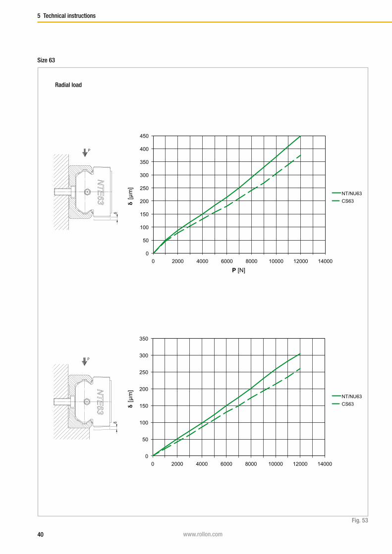
Rigidity
Total deformation
In the following deformation diagrams the total deviation of the linear gui-
de is indicated under the effect of external loads P or moments M.
As seen from the graphs, the rigidity can be increased by supporting the
sides of the rails. The graph values indicate only the deformation of the
linear guide, the supporting structure is assumed infinitely rigid. All graphs
refer to sliders with 3 rollers and K1 preload (standard setting). An increa-
sed preload, K2, reduces the deformation values by 25 %.
Fig. 51
Radial load
Size 18 - 43

39www.rollon.com
0
20
40
60
80
100
120
140
0 200 400 600 800 1000 1200 1400 1600
δ [μ
m]
P [N]
18
28
35
43
0
2
4
6
8
10
12
14
0 2 4 6 8 10 12 14 16 18 20 22 24
δ [m
rad]
Mx [Nm]
18
28
35
43
δ
Mx
δ
P
Technical instructions 5
Fig. 52
Axial load
Moment Mx
40 www.rollon.com
5 Technical instructions
Fig. 53
Size 63
0
50
100
150
200
250
300
350
0 2000 4000 6000 8000 10000 12000 14000
δ [μm
]
P [N]
NT/NU63
CS63
0
50
100
150
200
250
300
350
400
450
0 2000 4000 6000 8000 10000 12000 14000
δ [μm
]
P [N]
NT/NU63
CS63
δ
P
δ
P
Radial load

41www.rollon.com
Technical instructions 5
Fig. 54
0
20
40
60
80
100
120
140
160
180
200
0 1000 2000 3000 4000 5000 6000 7000
δ [μm
]
P [N]
NT63
CS63
0
2
4
6
8
10
12
14
16
18
0 25 50 75 100 125 150
δ [m
rad]
Mx [Nm]
NT63
CS63
δ
Mx
δ
P
Axial load
Moment Mx
42 www.rollon.com
5 Technical instructions
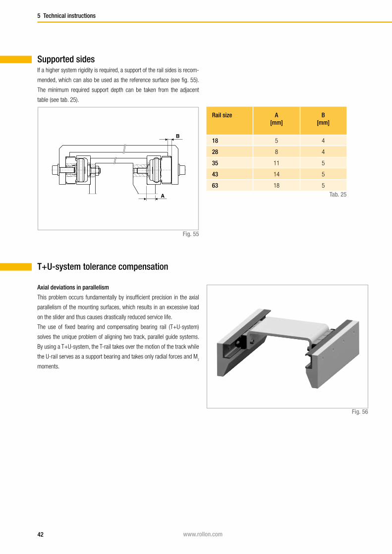
Supported sides
T+U-system tolerance compensation
Axial deviations in parallelism
This problem occurs fundamentally by insufficient precision in the axial
parallelism of the mounting surfaces, which results in an excessive load
on the slider and thus causes drastically reduced service life.
The use of fixed bearing and compensating bearing rail ( T+U-system)
solves the unique problem of aligning two track, parallel guide systems.
By using a T+U-system, the T-rail takes over the motion of the track while
the U-rail serves as a support bearing and takes only radial forces and Mz
moments.
Fig. 56
Rail size A[mm]
B[mm]
18 5 4
28 8 4
35 11 5
43 14 5
63 18 5
Tab. 25
Fig. 55
If a higher system rigidity is required, a support of the rail sides is recom-
mended, which can also be used as the reference surface (see fig. 55).
The minimum required support depth can be taken from the adjacent
table (see tab. 25).

43www.rollon.com
Technical instructions 5
Slider type S1
[mm]S2
[mm]Bmin
[mm]Bnom
[mm]Bmax
[mm]
NU18 0 1.1 16.5 16.5 17.6
CS18 0.3 1.1 14.7 15 16.1
NUE28NUE28L
0 1.3 24 24 25.3
CS28CD28
0.6 1.3 23.3 23.9 25.2
CS35 1.3 2.7 28.9 30.2 32.9
CD35 1.3 2.7 28.8 30.1 32.8
NUE43NUE43L
0 2.5 37 37 39.5
CS43 1.4 2.5 35.6 37 39.5
CD43 1.4 2.5 35.9 37.3 39.8
NUE63 0 3.5 50.5 50.5 54
CS63 0.4 3.5 49.4 49.8 53.3
Tab. 26
Fig. 57
T+U-system maximum offset
U-rails have flat parallel raceways that allow free lateral movement of the
sliders. The maximum axial offset that can be compensated for in each
slider of the U-rail is made up of the combined values S1 and S
2 listed in
table 26. Considered from a nominal value Bnom
as the starting point, S1
indicates the maximum offset into the rail, while S2 represents the maxi-
mum offset towards the outside of the rail.
Bmin.-S1
Bmax.+S2
Bnom.

44 www.rollon.com
5 Technical instructions
The application example in the adjacent drawing (see fig. 59) shows that
the T+U-system implements a problem-free function of the slider even
with an angled offset in the mounting surfaces.
If the length of the guide rails is known, the maximum allowable angle
deviation of the screwed surfaces can be determined using this formula
(the slider in the U-rail moves here from the innermost position S1 to ou-
termost position S2 ):
Size Rail length [mm]
Offset S[mm]
Angle α[°]
18 2000 1.4 0.040
28 3200 1.9 0.034
35 3600 4 0.063
43 3600 3.9 0.062
63 3600 3.9 0.062
S* = Sum of S1 and S
2
L = Length of rail
Fig. 58
Fig. 59
α = arctanS*L
The following table (tab. 27) contains guidelines for this maximum an-
gle deviation α, achievable with the longest guide rail from one piece.
Tab. 27
The T+U-system can be designed in different arrangements (see fig. 60).
A T-rail accepts the vertical components of load P. A U-rail attached un-
derneath the component to be guided prevents the vertical panel from
swinging and is used as moment support. In addition a vertical offset
in the structure, as well as possible existing unevenness of the support
surface, is compensated for.
Fig. 60
L
S
α

45www.rollon.com
Technical instructions 5
K+U-system tolerance compensation
Deviations in parallelism in two planes
The K+U-system, like the T+U-system, can compensate for axial devi-
ations in parallelism. Additionally, the K+U system has the option of ro-
tating the slider in the rail, which will compensate for other deviations in
parallelism, e.g. height offset.
The unique raceway contour of the K-rail allows the slider a certain ro-
tation around its longitudinal axis, with the same linear precision as with
a T-rail. With the use of a K+U-system, the K-rail accounts for the main
loads and the motion of the track. The U-rail is used as a support bearing
and takes only radial forces and Mz moments. The K-rail must always be
installed so that the radial load of the slider is always supported by at least
2 load bearing roller sliders, which lie on the V-shaped raceway (reference
line) of the rail.
Fig. 62
K-rails and sliders are available in both sizes 43 and 63.
The custom NKE-slider may only be used in K-rails and cannot be ex-
changed with other Rollon sliders. The maximum allowable rotation angle
of the NKE- and NUE-sliders are shown in the following table 28 and figure
62. α1 is the maximum rotation angle counterclockwise, α
2 is clockwise.
Slider type α1
[°]α2
[°]
NKE43 and NUE43 2 2
NKE63 and NUE63 1 1
Tab. 28
Fig. 61
NKE43
NU
E43
α α1α α
NKE
2
NKE
1α α
NKE
2
NKE
46 www.rollon.com
5 Technical instructions
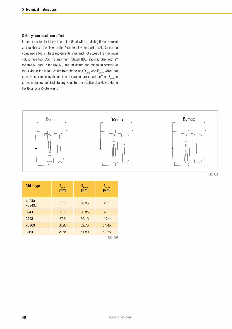
K+U-system maximum offset
It must be noted that the slider in the U-rail will turn during the movement
and rotation of the slider in the K-rail to allow an axial offset. During the
combined effect of these movements, you must not exceed the maximum
values (see tab. 29). If a maximum rotated NUE- slider is observed (2°
for size 43 and 1° for size 63), the maximum and minimum position of
the slider in the U rail results from the values B0max and B
0min, which are
already considered by the additional rotation caused axial offset. B0nom
is
a recommended nominal starting value for the position of a NUE-slider in
the U-rail of a K+U-system.
Slider type B0min
[mm]B0nom
[mm]B0max
[mm]
NUE43NUE43L
37.6 38.85 40.1
CS43 37.6 38.85 40.1
CD43 37.9 39.15 40.4
NUE63 50.95 52.70 54.45
CS63 49.85 51.80 53.75
Tab. 29
Fig. 63
B0min B0nom B0max

47www.rollon.com
Technical instructions 5
Even the K+U-system can be used in different arrangements. If the same
example as with the T+U-system is observed (see pg. 44, fig. 60), this
solution, in addition to the prevention of vibrations and moments, also
enables the compensation of larger deviations in parallelism in the vertical
direction, without negative consequences to the guide. This is particularly
important for longer strokes as it is more difficult to obtain a correct ver-
tical parallelism.
Fig. 65
If a K-rail is used in combination with a U-rail, with guaranteed problem-
free running and without extreme slider load, a pronounced height diffe-
rence between the two rails can also be compensated for. The following
illustration shows the maximum height offset b of the mounting surfaces
in relation to the distance a of the rails (see fig. 64).
Fig. 64
100
75
50
25
0
-25
-50
-75
-100
0 250 500 750 1000 1250 1500 1750 2000 2250 2500
Size 43
Size 63
b -
max
imum
hei
ght o
ffset
(mm
)
a - distance between the rails (mm )
b
a
NKE43
NU
E43

48 www.rollon.com
5 Technical instructions
Preload
Preload classes
The factory installed systems, consisting of rails and sliders, are available
in two preload classes:
Standard preload K1 means a rail-slider combination with minimum pre-
load which means the rollers are adjusted free of clearance for optimal
running properties.
Usually preload K2 is used for rail-slider systems for increasing the rigidity
(see pg. 38ff). When using a system with K2 preload a reduction of the
loading capacities and service life must be taken into consideration (see
tab. 30).
Preload class Reduction y
K1 -
K2 0.1
Preload class Excess*[mm]
Rail type
K1 0.01 all
K2
0.03 T, U...18
0.04 T, U...28
0.05 T, U...35
0.06T, U, K...43, T, U, K...63
Tab. 30
Tab. 31
The excess is the distance between the contact lines of the roller pins
minus y. This coefficient y is used in the calculation formula for checking
the static load (see pg. 52, fig. 74).
* Measured on the largest interior dimension between the raceways

49www.rollon.com
Technical instructions 5
Size A[mm]
18 40
28 55
35 75
43 80
63 120
External preload
The unique design of the Compact Rail product family enables applying a
partial external preload on selected locations along the entire guide.
An external preload can be applied by pressure along the side surfaces
of the guide rail according to the drawing below (see fig. 66). This local
preload results in higher rigidity only at the locations where it is necessary
(e.g. on reversing points with high dynamic auxiliary forces).
This partial preload increases the service life of the linear guide by avo-
iding a continually increased preload over the entire length of the guide.
Also the required drive force of the linear carriage in the non-preloaded
areas is reduced.
The amount of the externally applied preload is determined using two dial
indicators by measuring the deformation of the rail sides. These are defor-
med by thrust blocks with pressure screws. The external preload must be
applied when the slider is not directly located in the pressure zone.
The graph below indicates the value of the equivalent load as a function
of the total deformation of both rail sides. The data relates to sliders with
three rollers (see fig. 67).
Fig. 66
Fig. 67
Tab. 32
δ [μm]
Equiv
ale
nt lo
ad [%
C0ra
d]
Dial indicator for determining the side deformation
A m
inim
um
Thrust block
Pressure screws

50 www.rollon.com
5 Technical instructions
Drive force
Frictional resistance
The drive force required for moving the slider is determined by the com-
bined resistance of the rollers, wipers and seals.
The surface machining of the raceways and rollers have a minimal coef-
ficient of friction, which remains almost the same in both the static and
dynamic state. The wiper and longitudinal seals are designed for an opti-
mum protection of the system, without a significant negative influence on
the quality of motion. The overall friction of the Compact Rail also depends
from external factors such as lubrication, preload and additional forces.
Table 33 below contains the coefficients of friction for each slider type (for
CSW and CDW sliders no friction occurs to μs ).
Fig. 68
Tab. 33
Size µ Roller friction µw Wiper friction µs Friction of longitudinal seals
18 0.003 0.0015
28 0.003
35 0.005
43 0.005
63 0.006
In ( m · 1000 )*
0.98 · m · 1000
In ( m · 1000 )*
0.06 · m · 1000
In ( m · 1000 )*
0.15 · m · 1000
* Kilograms must be used for load m
The values given in Table 33 apply to external loads, which, with sliders
with three rollers, are at least 10 % of the maximum load rating. For cal-
culating the driving force for lower loads, please contact our Application
Engineering Department.
51www.rollon.com
Technical instructions 5
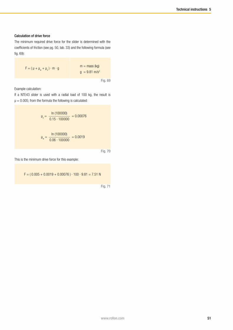
Calculation of drive force
The minimum required drive force for the slider is determined with the
coefficients of friction (see pg. 50, tab. 33) and the following formula (see
fig. 69):
Fig. 69
Example calculation:
If a NTE43 slider is used with a radial load of 100 kg, the result is
μ = 0.005; from the formula the following is calculated:
Fig. 70
In (100 000)
0.15 · 100 000μ
s = = 0.00076
In (100 000)
0.06 · 100 000μ
w = = 0.0019
This is the minimum drive force for this example:
F = ( 0.005 + 0.0019 + 0.00076 ) · 100 · 9.81 = 7.51 N
Fig. 71
F = ( μ + μw + μ
s ) · m · g
m = mass (kg)
g = 9.81 m/s2

52 www.rollon.com
5 Technical instructions
Static loadThe radial load capacity rating, C
0rad the axial load capacity rating C
0ax, and
moments Mx, M
y, M
z indicate the maximum permissible values of the load
(see pg. 12ff), higher loads will have a detrimental effect on the running
quality. A safety factor, S0, is used to check the static load, which takes
into account the basic parameters of the application and is defined more
in detail in the following table:
Safety factor S0
Fig. 72
No shock nor vibration, smooth and low-frequency reverse,
high assembly accuracy, no elastic deformations1 - 1.5
Normal installation conditions 1.5 - 2
Shock and vibration, high-frequency reverse, significant elastic deformation 2 - 3.5
Fig. 73
Fig. 74
The above formulas are valid for a single load case.
If two or more forces are acting simultaneously, please check the following
formula:
The ratio of the actual load to maximum permissible load may be as large
as the reciprocal of the accepted safety factor, S0, at the most.
P0rad
1
C0rad
S0
≤P
0ax 1
C0ax
S0
≤M
1 1
Mx S
0
≤M
2 1
My S
0
≤M
3 1
Mz S
0
≤
P0rad
= effective radial load (N)
C0rad
= permissible radial load (N)
P0ax
= effective axial load (N)
C0ax
= permissible axial load (N)
M1, M
2, M
3 = external moments ( Nm)
Mx, M
y, M
z = maximum permissible moments
in the different loading directions (Nm)
y = reduction due to preload
P0rad
P0ax
M1 M
2 M
3
C0rad
C0ax
Mx M
y M
z
+ + + + + y ≤1
S0
The safety factor S0 can lie on the lower given limit if the occurring forces
can be determined with sufficient precision. If shock and vibration are
present, the higher value should be selected. For dynamic applications
higher safety is required. Please contact the Application Engineering De-
partment.

53www.rollon.com
c
a b
FF
FP1 P2
M1
F
b a
F
P1
P2
b
a
F
P2a
P2b
P1a
P1b
F
Technical instructions 5
Examples of formulas for determining the forces on the most heavily loaded slider
For an explanation of the parameters in the formulas see pg. 55, fig. 89
Horizontal movement
Static test
Slider load:
Fig. 76
b
a+bP1
= F ·
P2 = F
- P
1
F
2M
1 =
· c
in addition each slider is
loaded by a moment:
Fig. 75
Horizontal movement
Static test
Slider load:
Fig. 78
Fig. 77
F
2P
1a ≅ P
2a =
P2b
≅ P1b
= F · a
b
Horizontal movement
Static test
Slider load:
Fig. 80
Fig. 79
a
bP
2 = F
·
P1 = P
2 + F
Calculation formulas

54 www.rollon.com
a
F
P1
M2
a
b
F
P2
P1
a
b
F
P2
P1
d
b
a
c
P1
P2
P3
P4
F
P3-4P1-2
5 Technical instructions
Horizontal movement
Static test
Slider load:
Fig. 82Fig. 81
Note: It is defined that slider no. 4 is always located closest to the point
where the force is applied.
F
4P
1 = - ( · ) - ( · )
F
2
b
c
F
2
a
d
F
4P
2 = - ( · ) + ( · )
F
2
b
c
F
2
a
d
F
4P
3 = + ( · ) - ( · )
F
2
b
c
F
2
a
d
F
4P
4 = + ( · ) + ( · )
F
2
b
c
F
2
a
d
Vertical movement
Static test
Slider load:
Fig. 84
Fig. 83
a
bP
1 ≅ P
2 = F ·
Horizontal movement
Static test
Slider load:
Fig. 86
Fig. 85
P1 = F
M2 = F · a

55www.rollon.com
Technical instructions 5
Fig. 87
Horizontal movement
Test with a moving element of the weight-force Fg at the instant the direc-
tion of movement changes
Fig. 88
Inertial force
F = m · a
Slider load at time of reverse
F · I
dP
1 =
+
Fg
2
Fg
2P
2 =
-
F · I
d
F = effective force (N)
Fg = weight-force (N)
P1, P
2, P
3, P
4 = effective load on the slider (N)
M1, M
2 = effective moment (Nm)
m = mass (kg)
a = acceleration (m/s²)
t
t
t
v
d
l
Fg
F
P1
P2
Direction
Drive
Center of gravity of the moving element
Fg
1 2t
t
t
v
t
t
t
v
d
l
Fg
F
P1
P2
Direction
Drive
Center of gravity of the moving element
Fg
1 2t
t
t
v
Fig. 89
Explanation of the calculation formula

56 www.rollon.com
5 Technical instructions
Service lifeThe dynamic load capacity C is a conventional variable used for calculating
the service life. This load corresponds to a nominal service life of 100 km.
For values of the individual slider see pg. 12ff Load capacities. The follow-
ing formula (see fig. 90) links the calculated theoretical service life to the
dynamic load capacity and the equivalent load:
Fig. 90
LKm
= 100 · ( ––– · ––– · fh )3
C
P
fc
fi
Lkm
= theoretical service life ( km )
C = dynamic load capacity ( N )
P = effective equivalent load ( N )
fc = contact factor
fi = application coefficient
fh = stroke factor
The equivalent load P corresponds in its effects to the sum of the forces
and moments working simultaneously on a slider. If these different load
components are known, P results as follows:
Pa
M1 M
2 M
3
C0ax
Mx M
y M
z
P = Pr + ( + + + ) · C
0rad
Fig. 91
Here the external loads are assumed as constant in time. Brief loads,
which do not exceed the maximum load capacities, do not have any rele-
vant effect on the service life and can therefore be neglected.
The contact factor fc refers to applications in which several sliders pass
the same rail section. If two or more sliders move over the same point of
a rail, the contact factor according to table 34 to be taken into account in
the formula for calculation of the service life.
Number of sliders 1 2 3 4
fc 1 0.8 0.7 0.63
Tab. 34

57www.rollon.com
Technical instructions 5
Fig. 92
fi
Neither shocks nor vibrations, smooth and low-frequency direction change;
clean operating conditions; low speeds (<1 m/s)1 - 1.5
Slight vibrations, average speeds (1 - 2.5 m/s) and average frequency of direction change 1.5 - 2
Shocks and vibrations, high speeds (> 2.5 m/s) and high-frequency direction change; extreme dirt contamination 2 - 3.5
The application coefficient fi takes into account the operational conditions
in the service life calculation. It has a similar significance to the safety
factor S0 in the static load test. It is calculated as described in the following
table:
The stroke factor fh takes into account the higher load of the raceways
and rollers during short strokes on the same total length of run. The cor-
responding values are taken from the following graph (for strokes longer
than 1 m, fh =1):
Tab. 35
Stroke [m]
f h
58 www.rollon.com
5 Technical instructions
Lubrication
Roller pin lubrication
The bearings inside the Rollers are lubricated for life. Custom lubrication
of the roller sliders for use in high temperature environments or in the food
Tab. 36
Lubrication of the raceways
Proper lubrication during normal conditions:
■ reduces friction
■ reduces wear
■ reduces the load of the contact surfaces through elastic deformations
■ reduces running noise
■ increases quiet running
Lubricant Thickening agent Temperature range[°C]
Dynamic viscosity[mPas]
Mineral oil Lithium soap -30... to +120 < 1000
To reach the calculated service life (see pg. 56), a film of lubricant should
always be present between the raceway and roller, this also serves to
protect against corrosion of the ground raceways.
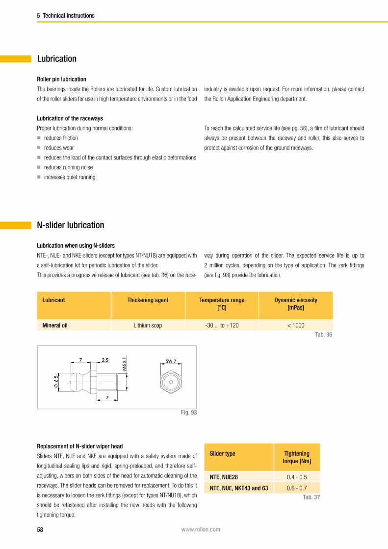
Fig. 93
Replacement of N-slider wiper head
Sliders NTE, NUE and NKE are equipped with a safety system made of
longitudinal sealing lips and rigid, spring-preloaded, and therefore self-
adjusting, wipers on both sides of the head for automatic cleaning of the
raceways. The slider heads can be removed for replacement. To do this it
is necessary to loosen the zerk fittings (except for types NT/NU18), which
should be refastened after installing the new heads with the following
tightening torque:
Slider type Tightening torque [Nm]
NTE, NUE28 0.4 - 0.5
NTE, NUE, NKE43 and 63 0.6 - 0.7
Tab. 37
N-slider lubrication
Lubrication when using N-sliders
NTE-, NUE- and NKE-sliders (except for types NT/NU18) are equipped with
a self-lubrication kit for periodic lubrication of the slider.
This provides a progressive release of lubricant (see tab. 36) on the race-
way during operation of the slider. The expected service life is up to
2 million cycles, depending on the type of application. The zerk fittings
(see fig. 93) provide the lubrication.
6,5
7 2,5
7
M6
x 1
SW 7
6,5
7 2,5
7
M6
x 1
SW 7
industry is available upon request. For more information, please contact
the Rollon Application Engineering department.
59www.rollon.com
Technical instructions 5
Lubricant Thickening agent Temperature range[°C]
Dynamic viscosity [mPas]
Roller bearing lubricant Lithium soap -30 to +170 4500
Tab. 38
Operating temperatures
C-slider lubrication
Lubrication when using C-sliders
The C series sliders can be provided with wipers made of polyamide, to
remove the contaminants on the raceways. Since the sliders do not have
a self-lubrication kit, manual lubrication of the raceways is required. A
guideline is to lubricate the raceways every 100 km or every 6 months.
We recommend a roller bearing lubricant with a lithium base of average
consistency as a lubricant (see tab. 38).
Corrosion protectionThe Compact Rail product family has a standard corrosion protection
system by means of electrolytic-zinc plating according to ISO 2081. If
increased corrosion protection is required, application-specific surface
treatments are available upon request, e.g. as nickel-plated design with
FDA approval for use in the food industry. For more information contact
the Rollon Application Engineering Department.
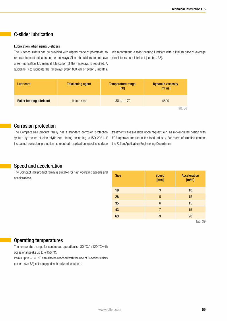
Speed and accelerationThe Compact Rail product family is suitable for high operating speeds and
accelerations. Size Speed
[m/s]Acceleration
[m/s2]
18 3 10
28 5 15
35 6 15
43 7 15
63 9 20
Tab. 39
The temperature range for continuous operation is: -30 °C / +120 °C with
occasional peaks up to +150 °C.
Peaks up to +170 °C can also be reached with the use of C-series sliders
(except size 63) not equipped with polyamide wipers.
60 www.rollon.com
Chamfer
6 Installation instructions
Fixing holes
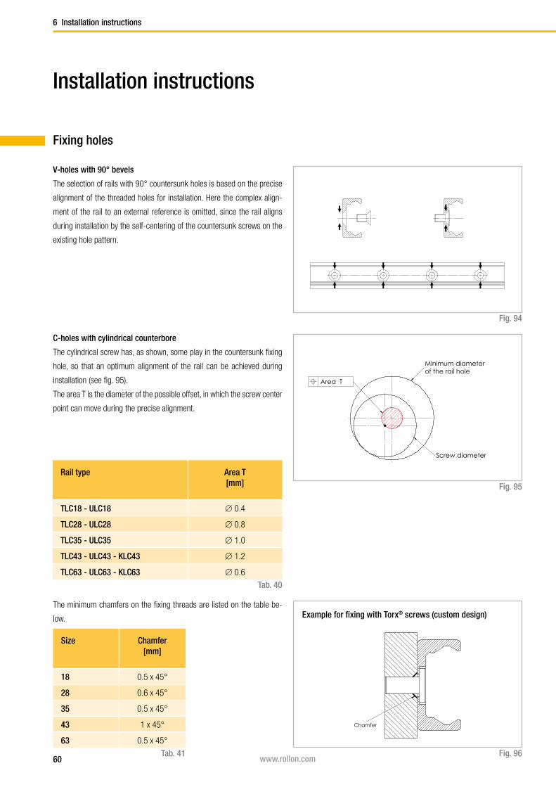
V-holes with 90° bevels
The selection of rails with 90° countersunk holes is based on the precise
alignment of the threaded holes for installation. Here the complex align-
ment of the rail to an external reference is omitted, since the rail aligns
during installation by the self-centering of the countersunk screws on the
existing hole pattern.
Fig. 94
C-holes with cylindrical counterbore
The cylindrical screw has, as shown, some play in the countersunk fixing
hole, so that an optimum alignment of the rail can be achieved during
installation (see fig. 95).
The area T is the diameter of the possible offset, in which the screw center
point can move during the precise alignment.
Fig. 95
Rail type Area T [mm]
TLC18 - ULC18 ∅ 0.4
TLC28 - ULC28 ∅ 0.8
TLC35 - ULC35 ∅ 1.0
TLC43 - ULC43 - KLC43 ∅ 1.2
TLC63 - ULC63 - KLC63 ∅ 0.6
Tab. 40
Installation instructions
The minimum chamfers on the fixing threads are listed on the table be-
low.
Size Chamfer[mm]
18 0.5 x 45°
28 0.6 x 45°
35 0.5 x 45°
43 1 x 45°
63 0.5 x 45°
Fig. 96Tab. 41
Minimum diameter of the rail hole
Screw diameter
Area T
Example for fixing with Torx® screws (custom design)

61www.rollon.com
Installation instructions 6
Normally the linear guides are delivered as a system consisting of rail and
adjusted sliders.
If rail and slider are delivered separately or if the slider is installed in ano-
ther raceway, the preload must be set again.
Setting the preload:
(1) Check the cleanliness of the tracks.
(2) Insert the slider in the rail (CSW and CDW sliders should be inserted
without wipers). Slightly loosen the fixing screws of the roller pins to be
adjusted.
( 3 ) Position the slider on one end of the rail.
(4 ) For the U rails there must be a thin support (e.g. set key) under the
ends of the slider body to ensure the horizontal alignment of the slider in
the flat raceways.
( 5) Insert the flat key on the side with the triangular symbol combined with
a red mark of the screw head (N-series slider), or on the side with a circle
symbol (CSW-, CDW-slider) between rail and slider.
(6) By turning the flat key clockwise, the roller to be adjusted is pressed
against the upper track and the slider is then without play. Avoid a preload
that is too high. It generates increased wear and reduces the service life.
(7) While holding the correct position of the roller pin with the adjustment
Adjusting the sliders
Fig. 97
Slider size Tightening torque [Nm]
18 3
28 7
35 12
43 12
63 35
Tab. 42
key, the fixing screw can be carefully tightened. The exact tightening tor-
que will be checked later (see fig. 97 and tab. 42).
(8) Move the slider in the rail and check the preload over the entire length
of the rail. It should move easily and the slider should not have play at any
location of the rail.
(9) For sliders with more than 3 rollers, repeat this process with each
eccentric roller pin. Always start with the first roller pin after the one with
the red marking.
Make sure that all roller pins have uniform contact to the raceways.
(10) Now tighten the fixing screws with the specified tightening torque
from the table while the flat key holds the angle adjustment of the pin. A
special thread in the roller pin secures the set position.
(11) Now install the wiper of the CSW- and CDW-sliders and ensure a
proper lubrication of the raceways.

62 www.rollon.com
6 Installation instructions
Installing the single railThe T- and K-rails can be installed in two positions relative to the external
force. For axial loading of the slider (fig. 98. pos. 2), the load capacity is
reduced because of the decline in contact area caused by the change in
position. Therefore, the rails should be installed in such a way that the load
on the rollers acts in the radial direction (fig. 98, pos. 1). The number of
fixing holes in the rail in combination with screws of property class 10.9
is dimensioned in accordance with the load capacity values. For critical
applications with vibrations or higher demand for rigidity, a support of the
rail (fig. 98, pos. 3) is advantageous.
This reduces deformation of the sides and the load on the screws. The
installation of a rail with countersunk holes requires an external reference
for alignment. This reference can also be used simultaneously as rail sup-
port if required. All information in this section on alignment of the rails,
refers to rails with cylindrical countersunk holes. Rails with countersunk
holes self-align using the specified fixing hole pattern (see pg. 60, fig. 94 ).
Fig. 98
1 2 3

63www.rollon.com
Installation instructions 6
Fig. 99
Rail installation with reference surface as support
(1) Remove unevenness, burrs and dirt from the support surface.
(2) Press the rail against the support surface and insert all screws without
tightening them.
(3) Start tightening the fixing screws to the specified torque on one end of
the rail while continuing to hold pressure on the rail against the support
surface.
Screw type Tightening torque [Nm]
M4 (T..., U... 18) 3
M5 (T..., U... 28) 9
M6 (T..., U... 35) 12
M8 (T..., U..., K... 43) 22
M8 (T..., U..., K... 63) 35
Tab. 43
Fig. 100

64 www.rollon.com
6 Installation instructions
Fig. 101
Fig. 102
Fig. 103
Rail installation without support
(1) Carefully lay the guide rail with installed slider on the mounting surface
and slightly tighten the fixing screws so that the guide rail lightly touches
the mounting surface.
(2) Install a dial indicator so that the offset of the rail to a reference line
can be measured. Now position the slider in the center of the rail and set
the dial indicator to zero. Move the slider back and forth between each two
hole spacings and carefully align the rail. Fasten the three center screws
of this area now with the the specified tightening torque, see pg. fig. 102
(3) Now position the slider on one end of the rail and carefully align the rail
to zero on the dial indicator.
(4) Begin to tighten the screws as specified while moving the slider toge-
ther with the dial indicator. Make sure that it does not show any significant
deflection. Repeat this procedure from the other end of the rail.
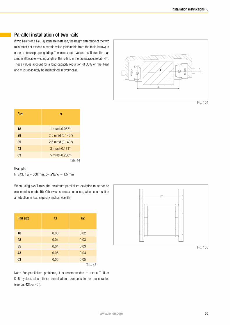
65www.rollon.com
Installation instructions 6
If two T-rails or a T+U-system are installed, the height difference of the two
rails must not exceed a certain value (obtainable from the table below) in
order to ensure proper guiding. These maximum values result from the ma-
ximum allowable twisting angle of the rollers in the raceways (see tab. 44).
These values account for a load capacity reduction of 30% on the T-rail
and must absolutely be maintained in every case.
Size α
18 1 mrad (0.057°)
28 2.5 mrad (0.143°)
35 2.6 mrad (0.149°)
43 3 mrad (0.171°)
63 5 mrad (0.286°)
Tab. 44
Fig. 104
Example:
NTE43: if a = 500 mm; b= a*tanα = 1.5 mm
When using two T-rails, the maximum parallelism deviation must not be
exceeded (see tab. 45). Otherwise stresses can occur, which can result in
a reduction in load capacity and service life.
Rail size K1 K2
18 0.03 0.02
28 0.04 0.03
35 0.04 0.03
43 0.05 0.04
63 0.06 0.05
Tab. 45
Fig. 105
Note: For parallelism problems, it is recommended to use a T+U or
K+U system, since these combinations compensate for inaccuracies
(see pg. 42f, or 45f ).
Parallel installation of two rails
a
bα
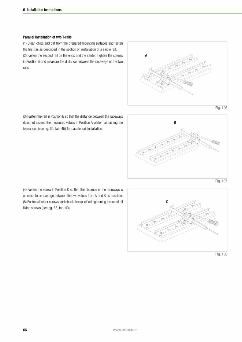
66 www.rollon.com
6 Installation instructions
(1) Clean chips and dirt from the prepared mounting surfaces and fasten
the first rail as described in the section on installation of a single rail.
(2) Fasten the second rail on the ends and the center. Tighten the screws
in Position A and measure the distance between the raceways of the two
rails.
Fig. 106
Fig. 107
Fig. 108
Parallel installation of two T-rails
(3) Fasten the rail in Position B so that the distance between the raceways
does not exceed the measured values in Position A while maintaining the
tolerances (see pg. 65, tab. 45 ) for parallel rail installation.
(4) Fasten the screw in Position C so that the distance of the raceways is
as close to an average between the two values from A and B as possible.
(5) Fasten all other screws and check the specified tightening torque of all
fixing screws ( see pg. 63, tab. 43).
A
B
C
67www.rollon.com
Installation instructions 6
When using a two-track parallel linear guide we recommend the use of a
fixed bearing / compensating bearing system: The combination of T+U-
rails for compensation of deviations in parallelism or the K+U-system to
compensate for deviations in parallelism in two planes.
Installation of the T+U- or the K+U-system
Fig. 109
Fig. 110
Installation steps
(1) For a fixed bearing / compensating bearing system the fixed bearing
rail is always installed first. This is then used as a reference for the com-
pensating bearing rail.
Then proceed as described in the section on installation of a single rail
(see pg. 62ff).
(2) Install the compensating bearing rail and only tighten the fixing screws
slightly.
(3) Insert the sliders in the rails and install the element to be moved,
without tightening its screws.
(4) Insert the element in the center of the rails and tighten it with the
correct tightening torque (see pg. 61, tab. 42 ).
(5) Tighten the center rail fixing screws to the specified torque
(see fig. 110).
(6) Move the element to one end of the rail and start tightening the rest of
the screws in the direction away from the slider.
Fig. 111

68 www.rollon.com
A A
A1 A1 A2 A2
B2B2B1 B1
A A
A1 A1 A2 A2
B2B2B1 B1
6 Installation instructions
If long guide rails are required, two or more rails can be joined to the
desired length. When putting guide rails together, be sure that the register
marks shown in fig. 112 are positioned correctly.
These are fabricated asymmetric for parallel application of joined guide
rails, unless otherwise specified.
Fig. 112
Two rails
Several rails
Comp. L
Comp. L
Joint
Joint marks
Joint marks
Joint marks
Joint marks
Joint marks
Joint
Joint
Joint
Joint
Joined Rails
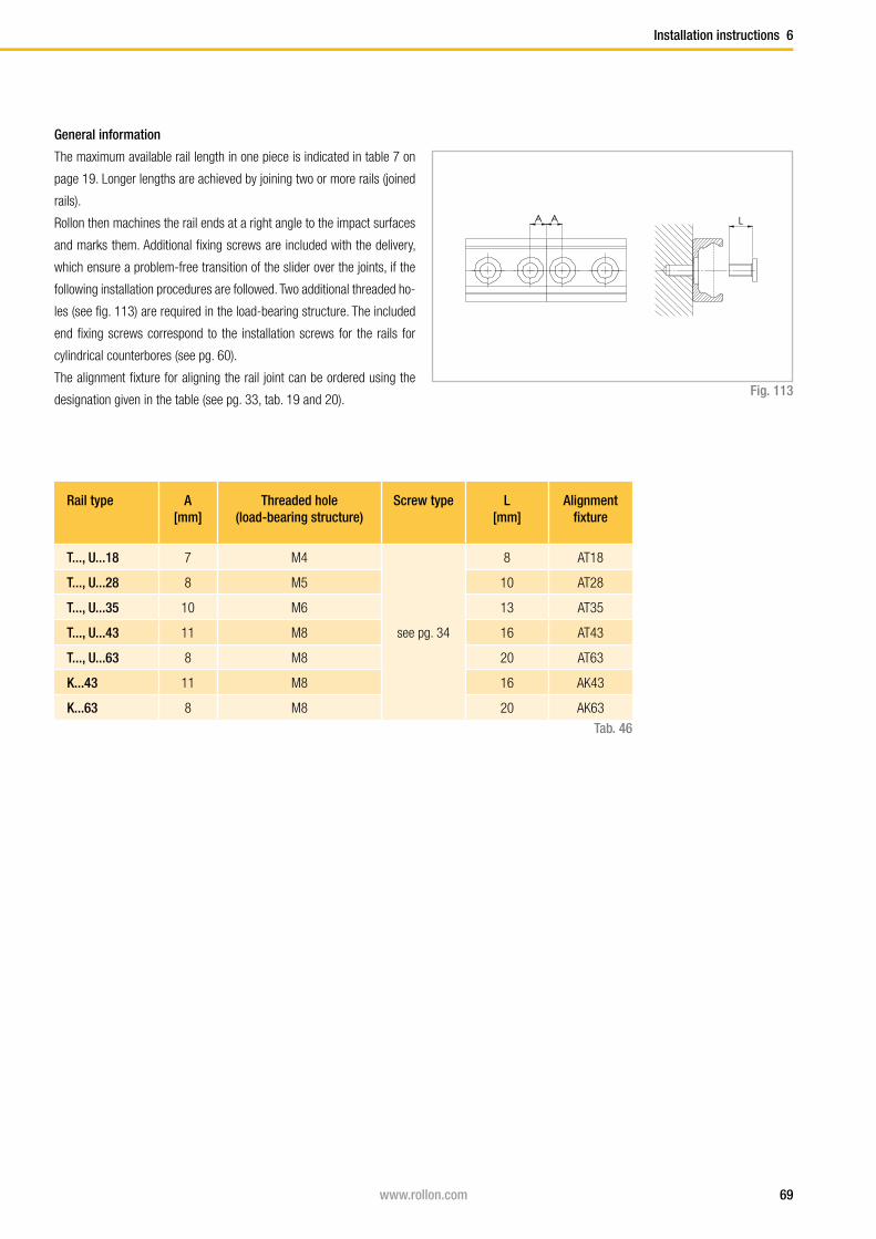
69www.rollon.com
Installation instructions 6
General information
The maximum available rail length in one piece is indicated in table 7 on
page 19. Longer lengths are achieved by joining two or more rails (joined
rails).
Rollon then machines the rail ends at a right angle to the impact surfaces
and marks them. Additional fixing screws are included with the delivery,
which ensure a problem-free transition of the slider over the joints, if the
following installation procedures are followed. Two additional threaded ho-
les (see fig. 113) are required in the load-bearing structure. The included
end fixing screws correspond to the installation screws for the rails for
cylindrical counterbores (see pg. 60).
The alignment fixture for aligning the rail joint can be ordered using the
designation given in the table (see pg. 33, tab. 19 and 20).Fig. 113
Rail type A[mm]
Threaded hole (load-bearing structure)
Screw type L [mm]
Alignment fixture
T..., U...18 7 M4
see pg. 34
8 AT18
T..., U...28 8 M5 10 AT28
T..., U...35 10 M6 13 AT35
T..., U...43 11 M8 16 AT43
T..., U...63 8 M8 20 AT63
K...43 11 M8 16 AK43
K...63 8 M8 20 AK63
Tab. 46
A A LA A L

70 www.rollon.com
6 Installation instructions
Installation of joined rails
After the fixing holes for the rails are made in the load-bearing structure,
the joined rails can be installed according to the following procedure:
(1) Fix the individual rails on the mounting surface by tightening all screws
except for each last one on the rail joint.
(2) Install the end fixing screws without tightening them (see fig. 114).
Fig. 114
(3) Place the alignment fixture on the rail joint and tighten both set screws
uniformly, until the raceways are aligned (see fig. 115).
(4) After the previous step (3) it must be checked if both rail backs lie
evenly on the mounting surface. If a gap has formed there, this must be
shimmed.
(5) The bottom of the rails should be supported in the area of the transiti-
on. Here a possible existing gap must be looked for, which must be closed
if necessary for correct support of the rail ends by shims.
(6) Insert the key through the holes in the alignment fixture and tighten the
screws on the rail ends.
(7) For rails with 90° countersunk holes, tighten the remaining screws
starting from the rail joint in the direction of the rail center. For rails with
cylindrical counter-sunk holes, first adjust the rail to an external reference,
then proceed as described above.
(8) Remove the alignment fixture from the rail.
A AA A
Fig. 115
Fig. 116
Fig. 117

Notes
Notes

Ordering Key
Ordering Key
TLC 4560 /2/ CD W 28 -125 -2Z -B -NIC
Expanded surface pro-
tection if deviation from
Standard ISO 2081
see pg. 59
Configuration depending on type of
slider see pgs. 24 and 26
Roller seal see pg. 32
Slider length Dimension A see pg. 20ff, tab. 8-11
Size see pg. 20ff
Wiper optional see pg. 33, fig. 43
Slider type see pg. 20ff
Number of sliders in one rail
Rail length in mm see pg. 19, tab. 7
Rail type see pg. 16ff
Rail / slider system
Ordering example: TLC-04560/2/CDW28-125-2Z-B-NIC
Rail composition: 1x3280+1x1280 (only for joint processed rails)
Hole pattern: 40-40x80-40//40-15x80-40 (please always specify the hole pattern separately)
Notes on ordering: The rail length codes are always 5 digits, the slider length codes are always 3 digits; use zeroes as a prefix when lengths are shorter
TLV -43 -5680 -NIC
Expanded surface protection if deviation from Standard ISO 2081 see pg. 59
Rail length in mm see pg. 19, table 7
Size see pg. 16ff
Rail type see pg. 16ff
Rail
Ordering example: TLV-43-05680-NIC
Rail composition: 1x880+2x2400 (only for joint processed rails)
Hole pattern: 40-10x80-40//40-29x80-40//40-29x80-40 (please always specify the hole pattern separately)
Notes on ordering: The rail length codes are always 5 digits; use zeroes as a prefix when lengths are shorter

Ordering Key
CS 28 -100 -2RS -B -NIC
Expanded surface protection if deviation from Standard ISO 2081
see pg. 59
Configuration depending on type of slider see pgs. 24 and 26
Roller seal see pg. 32
Slider length Dimension A see pg. 20ff, table 8-11
Size see pg. 20ff
Slider type see pg. 20ff
Slider
Ordering example: CS28-100-2RS-B-NIC
Notes on ordering: The slider length codes are always 3 digits; use zeroes as a prefix when lengths are shorter
WT 28
Size see pg. 20ff
Wiper type see pg. 33, fig. 43
Wipers
Ordering example: WT28
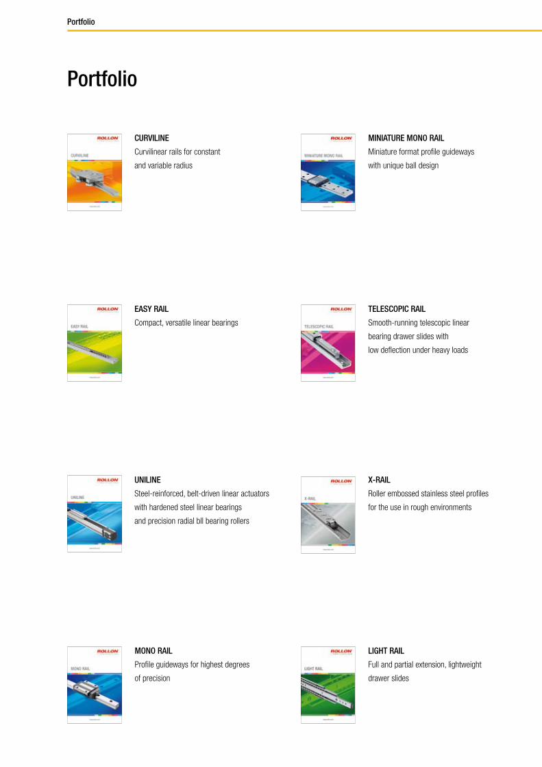
Portfolio
Portfolio
UNILINE
Steel-reinforced, belt-driven linear actuators
with hardened steel linear bearings
and precision radial bll bearing rollers
MONO RAIL
Profile guideways for highest degrees
of precision
MINIATURE MONO RAIL
Miniature format profile guideways
with unique ball design
TELESCOPIC RAIL
Smooth-running telescopic linear
bearing drawer slides with
low deflection under heavy loads
LIGHT RAIL
Full and partial extension, lightweight
drawer slides
CURVILINE
Curvilinear rails for constant
and variable radius
EASY RAIL
Compact, versatile linear bearings
X-RAIL
Roller embossed stainless steel profiles
for the use in rough environments

Fold out ordering key
Ordering key
To make this product catalog as simple as possible for you to use, we have
included the following easy-to-read chart.
Your advantages:
■ Description and ordering designations easy to read at one glance
■ Simplified selection of the correct product
■ Links to detailed descriptions in the catalog

Italy
Germ
any
ROLLON GmbH
Voisweg 5c
D-40878 Ratingen
Tel.: (+49) 21 02 87 45 0
Fax: (+49) 21 02 87 45 10
E-Mail: [email protected]
www.rollon.de
RL_CR_EN_12/11
ROLLON S.r.l.
Via Trieste 26
I-20059 Vimercate (MB)
Tel.: (+39) 039 62 59 1
Fax: (+39) 039 62 59 205
E-Mail: [email protected]
www.rollon.itNe
therland
s
ROLLON B.V.
Edisonstraat 32b
NL-6902 PK Zevenaar
Tel.: (+31) 316 58 19 99
Fax: (+31) 316 34 12 36
E-Mail: [email protected]
www.rollon.nl
France
ROLLON S.A.R.L.
Les Jardins d‘Eole, 2 allée des Séquoias
F-69760 Limonest
Tel.: (+33) (0)4 74 71 93 30
Fax: (+33) (0)4 74 71 95 31
E-Mail: [email protected]
www.rollon.fr USA
ROLLON Corporation
30A Wilson Drive
Sparta, NJ 07871, USA
Tel.: (+1) 973 300 5492
Fax: (+1) 973 300 9030
E-Mail: [email protected]
www.rolloncorp.com
All addresses of our global sales partners can also
be found on the internet at www.rollon.com
Changes and errors excepted. The text and images may be used only with our permission.