compact cylinder series cqs - rs components · symbol. — without auto ... compact...
TRANSCRIPT

1-371
Ideal for machine designs with small space requirementsThe “D-A9�” and “D-M9�” auto switches will not protrude from switch mounting groove.
Compact Cylinder
Series CQS ø12, ø16, ø20, ø25
Square body shape gives you flexibility for machine design
Auto switch mounting allows for flexible designing requirements3 faces on ø12 & ø16, and all 4 faces including port side on ø20, ø25.
2 way basic mounting: Through-hole or both ends tappedBasic mounting is 2 way. You can choose either through-hole or both ends tapped mounting.
Non-rotating piston rod model Superior non-rotating accuracyHexagonal cross sectional shape piston rod for high non-rotation accuracy.ø12, ø16 —— ±1°ø20, ø25 —— ±0.7°
Attachable on 4
sides. (ø20, ø25)
Attachable on 3
sides. (ø12, ø16)
Auto switch
Variations
Bas
ic
Non-
rota
ting
Rod
Anti-
late
ral L
oad
Series CQS
Series CQSW
Series CQS
Series CQSK
Series CQS�S
∗ Non-rotating rod/Doubleacting double rod can bemade.
Do
ub
le A
ctin
gSi
ngle
Act
ing
Doub
le Ac
ting
Doub
le Ac
ting
Sin
gle
Ro
dD
oubl
e R
odRe
turn
/Ext
end
Sin
gle
Ro
dS
ing
le R
od
Variations (Standard)Basicmodel
1∗
1∗
2∗
Solid state switchD-M9N, M9NV D-M9P, M9PVD-M9B, M9BVD-M9NW, M9NWVD-M9PW, M9PWVD-M9BW, M9BWV
Applicableauto switch
Boresize(mm)
Reed switchD-A90, A90VD-A93, A93VD-A96, A96V
∗1 Standard equipment on long stroke model/anti-lateral load model∗2 Available only for standard stroke model
12, 1620, 25
Stroke (mm)
Standard strokeø12ø16ø20ø25
5, 10, 15, 2025, 305, 10, 15, 2025, 30, 35, 4045, 50
Long strokeø12ø16ø20
ø25
35, 40, 45, 50, 7510075, 100, 125, 150175, 20075, 100, 125, 150175, 200, 250, 300
ø12ø16
5, 10, 15, 2025, 30
ø20ø25
5, 10, 15, 2025, 30, 35, 4045, 50
ø12ø16ø20ø25
5, 10
ø12ø16
5, 10, 15, 2025, 30
ø20ø25
5, 10, 15, 2025, 30, 35, 4045, 50
ø12ø16
5, 10, 15, 2025, 30
ø20ø25
5, 10, 15, 2025, 30, 35, 4045, 50
Page
1-372
1-380
1-386
1-394
1-400
Built-in magnet
Rod end male thread
Rubber bumper
Foot/Flange mounting
Double clevis mounting
Clean Series
1-372
CQS
CDQS
D
D
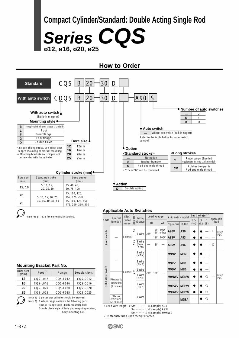
With auto switch(Built-in magnet)
Bore size12162025
12mm16mm20mm25mm
ActionD Double acting
Indi
cato
rY
esNo
Yes
Diagnosticindication(2 colour)
Waterresistant (2 colour)
2 wire 24V5V
12V100Vor less
100V12V
5V
12V24V
3 wire(Equiv. NPN)
3 wire(NPN)
3 wire(PNP)
2 wire
3 wire(NPN)
3 wire(PNP)
2 wire
Grommet
Grommet
Load voltage
DC AC
Auto switch model
Perpendicular In-line
Lead wire(m)∗
0.5(—)
3(L)
5(Z)
Ree
d sw
itch
Sol
id s
tate
sw
itch
A90V
A93V
A96V
M9NV
M9PV
M9BV
M9NWV
M9PWV
M9BWV
A90
A93
A96
M9N
M9P
M9B
M9NW
M9PW
M9BW
M9BA
IC
IC
RelayPLC
RelayPLC
Applicableload
Applicable Auto Switches
With auto switch
Standard 30
30
B
B
20
20
Mounting styleBLFGD
Through-hole/Both ends tapped (Standard)
FootFront flange Rear flange
Double clevis
Option
—CM
No optionRubber bumper
Rod end male thread
∗ "C" and "M" can be combined.Cylinder stroke (mm)
Mounting Bracket Part No.Bore size
(mm) Foot (1)
Flange
12162025
CQS-L012
CQS-L016
CQS-L020
CQS-L025
CQS-F012
CQS-F016
CQS-F020
CQS-F025
Double clevis
CQS-D012
CQS-D016
CQS-D020
CQS-D025
Note 1) 2 pieces per cylinder should be ordered.Note 2) Each package contains the following parts.
Foot or Flange style : Body mounting boltDouble clevis style :Clevis pin, snap ring retainer,
body mounting bolt.
Specialfunction
StyleElec-tricalentry
Wiring(Output)
Bore size(mm)
12, 16
20
25
Standard stroke(mm)
5, 10, 15, 20, 25, 30
5, 10, 15, 20, 25, 30, 35, 40, 45, 50
Long stroke(mm)
35, 40, 45, 50, 75, 100
75, 100, 125, 150, 175, 20075, 100, 125, 150, 175, 200, 250, 300
C
CM
Rubber bumper (Standardequipment for long stroke model)
Rubber bumper &Rod end male thread
• Refer to p.1-373 for intermediate strokes.
<Long stroke>
∗ Lead wire length
∗ : Manufactured upon receipt of order.
0.5m ·········· — (Example) A933m ·········· L (Example) A93L5m ·········· Z (Example) M9NWZ
<Standard stroke>
Number of auto switches—Sn
2 1 n
Auto switch
Refer to the table below for auto switch symbol.
— Without auto switch (Built-in magnet)
A90 S
∗ In case of long stroke, use either ends tapped mounting or bracket mounting.
∗∗ Mounting brackets are shipped not assembled with the cylinder.
Compact Cylinder/Standard: Double Acting Single Rod
Series CQS ø12, ø16, ø20, ø25
How to Order

1-373
Pneumatic (Non-lube)
Double acting, single rod
Air
1.5MPa
1.0MPa
Without auto switch –10°C to 70°C (No freezing)
With auto switch –10°C to 60°C (No freezing)
Standard stroke: None Long stroke: Standard equipment
Female
JIS class 2
Standard stroke: Long stroke:
Through-hole/Both ends tapped
50 to 500 mm/s
Specifications
+1.00
+1.40
Intermediate StrokesMethod
Model no.
Standardstroke
Long stroke
Example
Method
Strokerange
Method
Strokerange
Spacer is attached on standard stroke body.
Refer to "How to Order" for standard model no.
Model no. : CQSB25-47DCQSB25-50D with 3mm width spacer inside.B dimension is 72.5mm.
Intermediate strokes at 5mmintervals are available by using spacers with standard stroke cylinders.
Intermediate strokes at 1mm intervals are available by using spacers with standard stroke cylinders.
Specify "–XB10" at the end of standard model number.
Intermediate strokes at 1mm intervals are available by using exclusive body with required stroke.
Intermediate strokes at 1mm intervals are available by using exclusive body with required stroke.
Model no. : CQSB25-47D-XB10
Makes 47stroke tube. B dimension is 69.5mm.
Exclusive body (–XB10)
Theoretical Force Unit: N
Bore size(mm)
12
16
20
25
Rod diameter(mm)
6
8
10
12
Operation
IN
OUT
IN
OUT
IN
OUT
IN
OUT
Piston area (mm2)
84.8
113
151
201
236
314
378
491
Operating pressure (MPa)
0.3
25
34
45
60
71
94
113
147
0.5
42
57
75
101
118
157
189
245
0.7
59
79
106
141
165
220
264
344
OUT IN
Style
Action
Fluid
Proof pressure
Max. operating pressure
Ambient & fluid temperature
Rubber bumper
Rod end thread
Rod end thread tolerance
Stroke length tolerance
Basic mounting
Operating piston speed
Stroke range
31 to 100
31 to 200
31 to 300
Bore size
12, 16
20
25
Stroke range
6 to 30
6 to 50
Bore size
12, 16
20, 25
Stroke range
35 to 100
55 to 200
55 to 300
Bore size
12, 16
20
25
Stroke range
1 to 30
1 to 50
Bore size
12, 16
20, 25
∗ Consult SMC for shorter stroke lengths than indicated in the table.
Minimum Strokes for Auto Switch Mounting Unit: mm
No. of auto switches
2
1
D-A9�, D-M9�WV
10
10∗
D-A9�V
10
5
D-M9N
15∗
15∗
D-M9 , D-M9�W
20∗
20∗
D-M9�V
5
5
D-M9BA
25∗
25∗
BP
Minimum Operating Pressure Unit: MPa
Bore size (mm)
Min. operating pressure (MPa)
12
0.07
16
0.07
20
0.05
25
0.05
Allowable Kinetic Energy Unit: J
Bore size (mm)
Standard
With rubber bumper
12
0.022
0.043
16
0.038
0.075
20
0.055
0.11
25
0.09
0.18
Available for all standard modelsof double acting single rod.
OptionOption
Rod end thread
Rubber bumper ∗
Availability
∗ Rubber bumper is a standard equipment for long stroke models.
Compact Cylinder/Standard: Double Acting Single Rod Series CQS
JIS symbol

1-374
Weight/Without Auto Switch Unit: g
Bore(mm)
12
16
20
25
Stroke (mm)
Standard stroke modelCalculation Example) CQSD20-20DCM• Cylinder weight:CQSB20-20D························101g• Option weight :Rod end male thread··············10g
:Rubber bumper·······················–2g:Double clevis·························· 92g
Total 201g
5
29
38
63
91
10
36
47
75
107
15
42
56
88
123
20
49
64
101
139
25
56
73
114
155
30
63
82
127
171
35
93
119
140
186
40
100
128
153
202
45
107
136
166
218
50
113
145
178
234
75
147
187
306
399
100
180
229
370
478
125
—
—
434
557
150
—
—
498
636
175
—
—
562
715
200
—
—
627
794
250
—
—
—
952
300
—
—
—
1110
Weight/With Auto Switch (Built-in magnet) Unit: g
( ): Long stroke modelNote 1) Do not add value shown in the table above to long stroke models.
Option Weights Unit: g
Male thread
NutRod end thread
Rubber bumper (1)
Foot (including bolt)
Front flange (including bolt)
Rear flange (including bolt)
Double clevis (including pin, retainer, bolt)
Bore size (mm) 12
1.5
1
0
55(53)
58(56)
56
34
16
3
2
1
65(61)
70(66)
66
40
20
6
4
–2
159(153)
143(137)
137
92
25
12
8
–3
181(172)
180(171)
171
127
Bore(mm)
12
16
20
25
Stroke (mm)
5
37
48
93
134
10
43
57
106
150
15
50
66
119
166
20
57
74
132
182
25
63
83
144
197
30
70
92
157
213
35
94
121
170
229
40
101
129
182
245
45
108
137
195
261
50
114
146
208
277
75
148
188
311
406
100
181
231
375
485
125
—
—
439
564
150
—
—
503
643
175
—
—
567
721
200
—
—
632
800
250
—
—
—
958
300
—
—
—
1116
20 CQS Bore size Stroke D (C)(M)
ø12, ø16, ø20, ø25
Copper Free
Copper free series
To eliminate influences of copper ions or halogen ions during CRT manufacturing processes, copper and fluorine materials are not used as component parts.
SpecificationsAction
Cylinder bore size
Proof pressure
Max. operating pressure
Rubber bumper
Piston speed
Mounting
Double acting single rod
ø12, ø16, ø20, ø25
1.5MPa
1.0MPa
Standard stroke: Without, Long stroke: With
50 to 500mm/s
Through-hole, Both ends tapped
Mounting
Series CQS

Precautions
Handling
Caution
q All loads to piston rod must be applied inaxial direction only.
• Unavoidable side loads to rod end must beless than the values in the graphs.
• Cylinder installation requires accurate alignment.
• Adoption of guide mechanism is strongly recommended for the case when CQS is used as stopper to prevent non-rotating piston rod from side loads.
w To secure a workpiece to the end of the piston rod, make sure to retract thepiston rod entirely, and place a wrench onthe portion of the rod that protrudes beyond the section. To tighten,take precautions to prevent the tighteningtorque from being applied to the non-rotating guide.
Snap Ring Installation/Removal
Caution
q For installation and removal, use an appropriate pair of pliers(tool for installing a C snap ring).
w Exercise caution even when using an appropriate pair of pliers (tool for installing a C snap ring), because of the possibility of the snap ringbecoming detached from the tip of thepliers and flying away, which could injurehumans or damage the peripheralequipment. After installing the snap ring,make sure that it is placed securely in thering groove before supplying air.
1-375
Compact Cylinder/Standard: Double Acting Single Rod Series CQS
1-376Note) Contact SMC for further information.
C(D)QSB D(M)Bore size Stroke
SMC Clean Series
Relief styleVacuum suction style
10
11
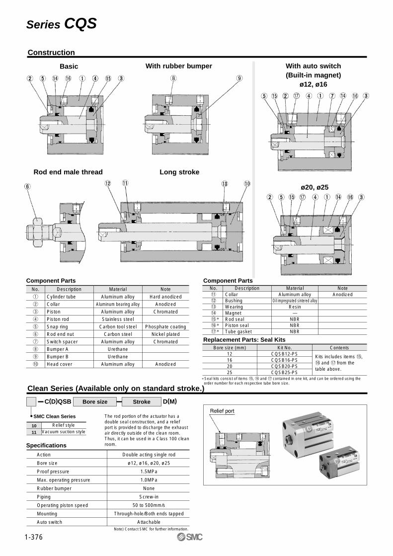
The rod portion of the actuator has adouble seal construction, and a reliefport is provided to discharge the exhaustair directly outside of the clean room.Thus, it can be used in a Class 100 clean room.Specifications
Action
Bore size
Proof pressure
Max. operating pressure
Rubber bumper
Piping
Operating piston speed
Mounting
Auto switch
Double acting single rod
ø12, ø16, ø20, ø25
1.5MPa
1.0MPa
None
Screw-in
50 to 500mm/s
Through-hole/Both ends tapped
Attachable
Component Parts Component PartsNo.
q
w
e
r
t
y
u
i
o
!0
Cylinder tube
Collar
Piston
Piston rod
Snap ring
Rod end nut
Switch spacer
Bumper A
Bumper B
Head cover
Description
Aluminum alloy
Aluminum bearing alloy
Aluminum alloy
Stainless steel
Carbon tool steel
Carbon steel
Aluminum alloy
Urethane
Urethane
Aluminum alloy
Material
Hard anodized
Anodized
Chromated
Phosphate coating
Nickel plated
Chromated
Anodized
NoteAnodized
No.!1
!2
!3
!4
!5
!6
!7
DescriptionCollarBushingWearingMagnetRod sealPiston sealTube gasket
MaterialAluminum alloy
Oil impregnated sintered alloyResin
—NBRNBRNBR
Note
Replacement Parts: Seal KitsBore size (mm)
12162025
Kit No.CQSB12-PSCQSB16-PSCQSB20-PSCQSB25-PS
Contents
Kits includes items !5, !6 and !7 from the table above.
∗Seal kits consist of items !5, !6 and !7 contained in one kit, and can be ordered using the order number for each respective tube bore size.
∗∗∗
Clean Series (Available only on standard stroke.)
Series CQS
Construction
Basic With rubber bumper With auto switch (Built-in magnet)
ø12, ø16
ø20, ø25
Rod end male thread Long stroke
1-377
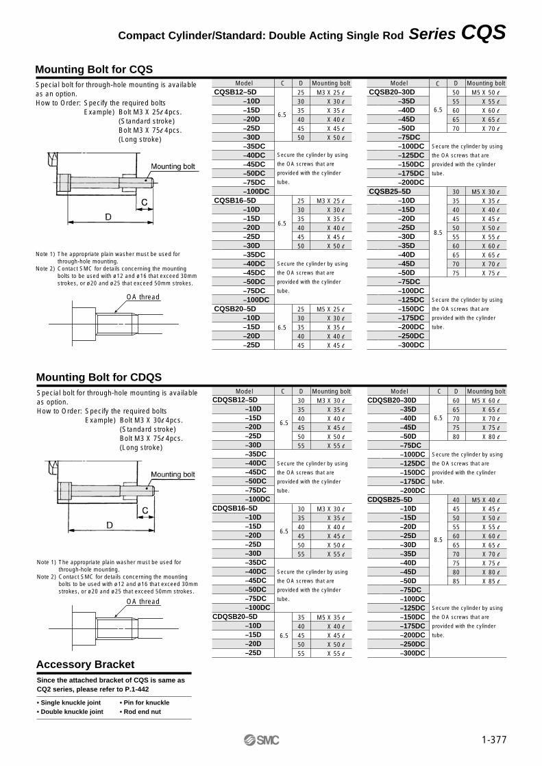
ModelSpecial bolt for through-hole mounting is available as an option.How to Order: Specify the required bolts
Example) Bolt M3 X 25l 4pcs. (Standard stroke)Bolt M3 X 75l 4pcs. (Long stroke)
Note 1) The appropriate plain washer must be used forthrough-hole mounting.
Note 2) Contact SMC for details concerning the mountingbolts to be used with ø12 and ø16 that exceed 30mmstrokes, or ø20 and ø25 that exceed 50mm strokes.
C D Mounting boltCQSB12–5DCQSB12 –10DCQSB12 –15DCQSB12 –20DCQSB12 –25DCQSB12 –30DCQSB12 –35DCCQSB12 –40DCCQSB12 –45DCCQSB12 –50DCCQSB12 –75DCCQSB12 –100DC CQSB16–5DCQSB12 –10DCQSB12 –15DCQSB12 –20DCQSB12 –25DCQSB12 –30DCQSB12 –35DCCQSB12 –40DCCQSB12 –45DCCQSB12 –50DCCQSB12 –75DCCQSB12 –100DC CQSB20–5DCQSB12 –10DCQSB12 –15DCQSB12 –20DCQSB12 –25D
6.5
6.5
6.5
253035404550
253035404550
2530354045
M3 X 25 lM3 X 30 lM3 X 35 lM3 X 40 lM3 X 45 lM3 X 50 lM3
M3 X 25 lM3 X 30 lM3 X 35 lM3 X 40 lM3 X 45 lM3 X 50 l
M5 X 25 lM3 X 30 lM3 X 35 lM3 X 40 lM3 X 45 l
Model C D Mounting boltCQSB20–30DCQSB20–35DCQSB20–40DCQSB20–45DCQSB20–50DCQSB20–75DCCQSB20–100DCCQSB20–125DCCQSB20–150DCCQSB20–175DCCQSB20–200DC CQSB25–5DCQSB20–10DCQSB20–15DCQSB20–20DCQSB20–25DCQSB20–30DCQSB20–35DCQSB20–40DCQSB20–45DCQSB20–50DCQSB20–75DCCQSB20–100DCCQSB20–125DCCQSB20–150DCCQSB20–175DCCQSB20–200DCCQSB20–250DCCQSB20–300DC
6.5
8.5
5055606570
30354045505560657075
M5 X 50 lM5 X 55 lM5 X 60 lM5 X 65 lM5 X 70 l
M5 X 30 lM5 X 35 lM5 X 40 lM5 X 45 lM5 X 50 lM5 X 55 lM5 X 60 lM5 X 65 lM5 X 70 lM5 X 75 l
Mounting Bolt for CQS
Secure the cylinder by using
the OA screws that are
provided with the cylinder
tube.
Secure the cylinder by using
the OA screws that are
provided with the cylinder
tube.
Secure the cylinder by using
the OA screws that are
provided with the cylinder
tube.
Secure the cylinder by using
the OA screws that are
provided with the cylinder
tube.
Model C D Mounting boltCDQSB12–5DCDQSB12–10DCDQSB12–15DCDQSB12–20DCDQSB12–25DCDQSB12–30DCDQSB12–35DCCDQSB12–40DCCDQSB12–45DCCDQSB12–50DCCDQSB12–75DCCDQSB12–100DC CDQSB16–5DCDQSB12–10DCDQSB12–15DCDQSB12–20DCDQSB12–25DCDQSB12–30DCDQSB12–35DCCDQSB12–40DCCDQSB12–45DCCDQSB12–50DCCDQSB12–75DCCDQSB12–100DCCDQSB20–5DCDQSB12–10DCDQSB12–15D CDQSB12–20DCDQSB12–25D
6.5
6.5
6.5
303540455055
303540455055
3540455055
M3 X 30 lM3 X 35 lM5 X 40 lM3 X 45 lM5 X 50 lM3 X 55 l
M3 X 30 lM3 X 35 lM5 X 40 lM3 X 45 lM5 X 50 lM3 X 55 l
M5 X 35 lM3 X 40 lM5 X 45 lM3 X 50 lM5 X 55 l
Model C D Mounting boltCDQSB20–30DCDQSB20–35DCDQSB20–40DCDQSB20–45DCDQSB20–50DCDQSB20–75DCCDQSB20–100DCCDQSB20–125DCCDQSB20–150DCCDQSB20–175DCCDQSB20–200DC CDQSB25–5DCDQSB20–10DCDQSB20–15DCDQSB20–20DCDQSB20–25D CDQSB20–30DCDQSB20–35DCDQSB20–40DCDQSB20–45D CDQSB20–50DCDQSB20–75DCCDQSB20–100DCCDQSB20–125DCCDQSB20–150DCCDQSB20–175DCCDQSB20–200DCCDQSB20–250DCCDQSB20–300DC
6.5
8.5
6065707580
40455055606570758085
M5 X 60 lM5 X 65 lM5 X 70 lM5 X 75 lM5 X 80 l
M5 X 40 lM5 X 45 lM5 X 50 lM5 X 55 lM5 X 60 lM5 X 65 lM5 X 70 lM5 X 75 lM5 X 80 lM5 X 85 l
Mounting Bolt for CDQSSpecial bolt for through-hole mounting is available as option.How to Order: Specify the required bolts
Example) Bolt M3 X 30l 4pcs. (Standard stroke)Bolt M3 X 75l 4pcs. (Long stroke)
Accessory BracketSince the attached bracket of CQS is same asCQ2 series, please refer to P.1-442
• Single knuckle joint • Pin for knuckle• Double knuckle joint • Rod end nut
Note 1) The appropriate plain washer must be used forthrough-hole mounting.
Note 2) Contact SMC for details concerning the mountingbolts to be used with ø12 and ø16 that exceed 30mmstrokes, or ø20 and ø25 that exceed 50mm strokes.
Secure the cylinder by using
the OA screws that are
provided with the cylinder
tube.
Secure the cylinder by using
the OA screws that are
provided with the cylinder
tube.
Secure the cylinder by using
the OA screws that are
provided with the cylinder
tube.
Secure the cylinder by using
the OA screws that are
provided with the cylinder
tube.
Compact Cylinder/Standard: Double Acting Single Rod Series CQS
OA thread
OA thread

1-378
X
10.51214
17.5
Rod end male thread(“L” is the only dimension that changes between standard stroke and long stroke.)
Bore(mm)
12162025
Standard stroke Long strokeL1
1415.518.522.5
L1
2425.528.532.5
C1
9101215
H1
M5M6M8
M10 X 1.25
Note 1) For the following bore/stroke sizes through-hole is threaded over the entire length: Basic style ø12 and ø16; 5 stroke, ø20; 5 to 15 stroke, ø25; 5 to 10 stroke, ø20 with auto switch built-in magnet; 5 stroke.
Note 2) Rubber bumper style has the same dimensions as those indicated above.∗ Refer to p.1-442 for details of the rod end nut and mounting brackets.
Basic (“A”, “B”, “F” and “L” are different between standard stroke and long stroke.)
Bore(mm)
• Length with intermediate stroke(1) Spacer ···The dimensions will be identical to those of the nearest long stroke.
Those that exceed the standard stroke will have the long stroke dimensions.(2) Exclusive body (-X10)···Add stroke. Stroke lengths that exceed standard are long stroke dimensions.
12162025
Standardstroke(mm)
5 to 305 to 305 to 505 to 50
Long stroke
With/Without auto switchA
45.545.555.559
B32324144
F7.57.59
11
L13.513.514.515
C
687
12
D
68
1012
E
25293640
H
M3M4M5M6
I
32384752
K
568
10
M
15.52025.528
N
3.53.55.45.4
OA
M4M4M6M6
OB
6.56.599
Q
7.57.59
11
RA
771010
RB
4477
T
0.50.511
Longstroke(mm)
35 to 10035 to 10075 to 20075 to 300
Standard strokeWithout auto switch With auto switchA
20.520.524
27.5
B171719.522.5
F55
5.55.5
L3.53.54.55
A25.525.53437.5
B2222
29.532.5
F55
5.55.5
L3.53.54.55
Series CQSDimensions/ø12 to ø25
∗Refer to p.1-408 for mounting position and height of auto switch.
Basic (Through-hole/Both ends tapped)/CQSB, CDQSB
ø12
ø16
ø20,
Rod end male thread

1-379
Bore(mm)
Standardstroke(mm)
Longstroke(mm)
Standard stroke (mm)Without auto switch With auto switch Without/with auto switch
Long stroke
Standard stroke (mm)Without auto switch With auto switch Without/with auto switch
Long stroke
Standard stroke (mm)Without auto switch With auto switch Without/with auto switch
Long stroke
Standard stroke (mm)Without auto switch With auto switch Without/with auto switch
Long stroke
12162025
Bore(mm)
12162025
Bore(mm)
12162025
Bore(mm) L
12162025
5 to 305 to 305 to 505 to 50
35 to 10035 to 10075 to 20075 to 300
Standardstroke(mm)
Longstroke(mm)
5 to 305 to 305 to 505 to 50
35 to 10035 to 10075 to 20075 to 300
Bore(mm)
12162025
Bore(mm)
12162025
Standardstroke(mm)
Longstroke(mm)
5 to 305 to 305 to 505 to 50
262632
35.5
A
40.541.551
57.5
A
558
10
CD
4455
CT
7101214
CU
14151820
CW
56.58
10
CX
10121620
CZ
669
10
RR
1717
19.522.5
B34.535.542
47.5
CL3.53.54.55
L14
15.518.522.5
L1
45.546.561
67.5
A2222
29.532.5
B39.540.552
57.5
CL3.53.54.55
L14
15.518.522.5
L1
65.566.582.589
A32324144
B59.560.573.579
CL13.513.514.515
L24
25.528.532.5
L1
FD
4.54.56.66.6
FT
5.55.588
FV
25303942
FX
45454852
FZ
55556064
B L L1 A B L L1 A B L L1
1717
19.522.5
3.53.54.55
1415.518.522.5
313142
45.5
2222
29.532.5
3.53.54.55
1415.518.522.5
5151
63.567
32324144
13.513.514.515
2425.528.532.5
35 to 10035 to 10075 to 20075 to 300
Bore(mm)
12162025
Bore(mm)
12162025
Standardstroke(mm)
Longstroke(mm)
5 to 305 to 305 to 505 to 50
35 to 10035 to 10075 to 20075 to 300
30.530.534
37.5
A1717
19.522.5
B35.535.544
47.5
A2222
29.532.5
B45.545.555.559
A32324144
B
35.335.341.244.7
A1717
19.522.5
B55
7.57.5
LS40.340.351.254.7
A2222
29.532.5
B1010
17.517.5
LS50.350.362.766.2
A32324144
B20202929
LS
13.513.514.515
FD
4.54.56.66.6
FT
5.55.588
FV
25303942
FX
45454852
FZ
55556064
L
13.513.514.515
L1
2425.528.532.5
L1
2425.528.532.5
LD
4.54.56.66.6
LG
2.82.844
LH
17192426
LT
22
3.23.2
LX
34384852
LY
29.533.54246
LZ
44486266
X
88
9.210.7
Y
4.55
5.85.8
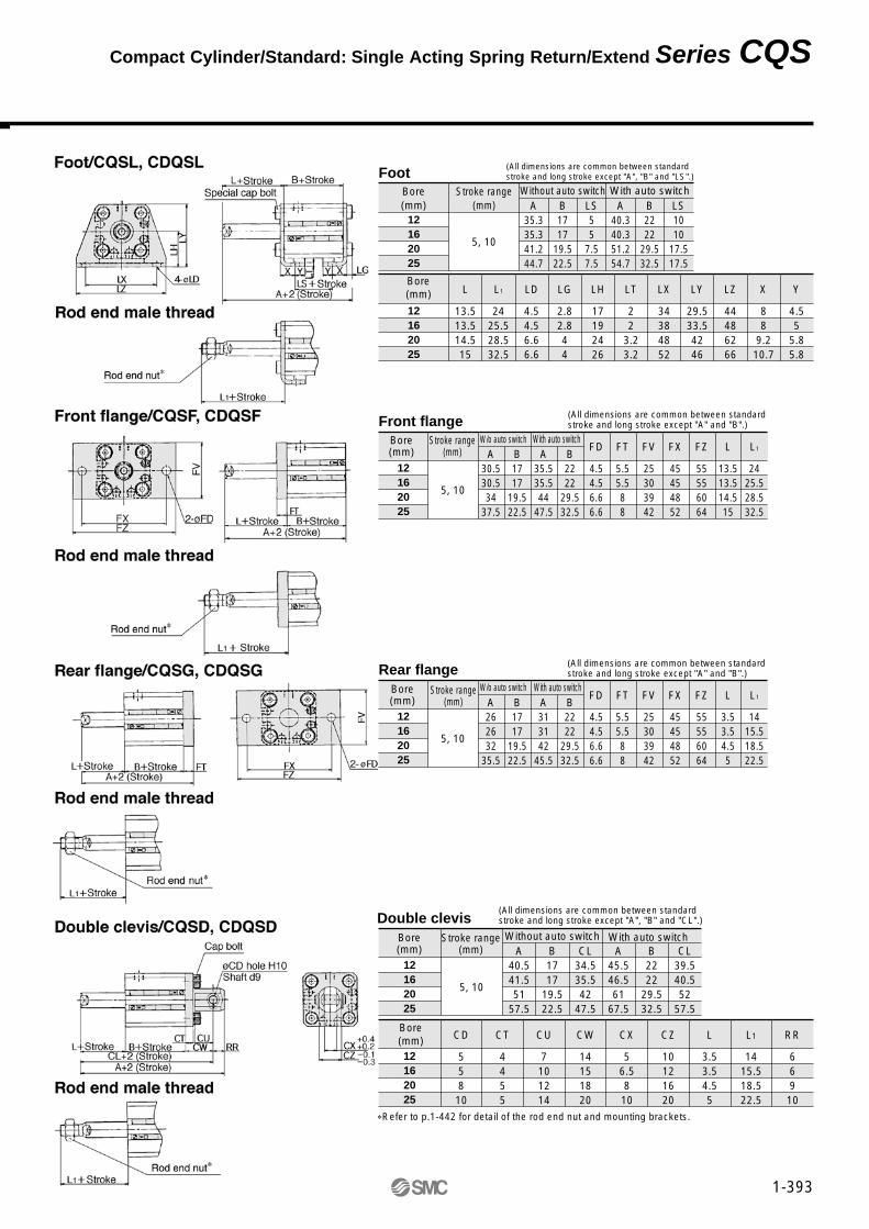
Foot
Front flange
Rear flange
Double clevis
(All dimensions are common between standardstroke and long stroke except "A", "B", and "LS".)
(All dimensions are common between standardstroke and long stroke except "A" and "B".)
(All dimensions are common between standardstroke and long stroke except "A", "B", "L" and "L1".)
(All dimensions are common between standard strokeand long stroke except "A", "B", "C", "L" and "L1".)
∗ Refer to P.1-442 for detail of the rod end nut and mounting brackets.
Compact Cylinder/Standard: Double Acting Single Rod Series CQS

CQSW
CDQSW
D
D
With auto switch(Built-in magnet)
Bore size12162025
12mm16mm20mm25mm
ActionD Double acting
With auto switch
Standard 30 C
30 C
B
B
20
20
Mounting styleBLF
Through-hole/Both ends tappedFoot
Flange
Option—CM
No optionRubber bumper
Rod end male thread
∗ "C" and "M" can be combined.
Cylinder stroke (mm)
Mounting Bracket Part No.Bore size
(mm) Foot(1)
Flange
12162025
CQS-L012
CQS-L016
CQS-L020
CQS-L025
CQS-F012
CQS-F016
CQS-F020
CQS-F025
Standard strokeBore (mm)
5 , 10, 15, 20, 25, 30
5 , 10, 15, 20, 25, 30, 35, 40, 45, 50
Standard stroke (mm)
12, 16
20, 25
Indi
cato
rY
esNo
Yes
Diagnosticindication(2 colour)
Waterresistant(2 colour)
Wiring(Output)
2 wire 24V5V
12V100Vor less
100V12V
5V
12V24V
3 wire(Equiv.NPN)
3 wire(NPN)
3 wire(PNP)
2 wire
3 wire(NPN)
3 wire(PNP)
2 wire
Elec-tricalentry
Grommet
Grommet
Load voltage
DC AC
Auto switch model
Perpendicular In-line
Lead wire (m)∗
0.5(—)
3(L)
5(Z)
Ree
d sw
itch
Sol
id s
tate
sw
itch
A90V
A93V
A96V
M9NV
M9PV
M9BV
M9NWV
M9PWV
M9BWV
A90
A93
A96
M9N
M9P
M9B
M9NW
M9PW
M9BW
M9BA
IC
IC
RelayPLC
RelayPLC
Applicableload
Applicable Auto Switches
SpecialfunctionStyle
Note 1) 2 pieces per cylinder should be ordered.Note 2) Each package contains the following parts.
Foot or Flange style : Body mounting bolt
∗ Lead wire length
∗ : Manufacutured upon receipt of order.
0.5m ·········· — (Example) A933m ·········· L (Example) A93L5m ·········· Z (Example) M9NWZ
∗ Refer to table below for auto switch no.
Number of auto switches—Sn
21n
Auto switch— Without auto switch (Built-in magnet)
A90 S
1-380
Compact Cylinder/Standard: Double Acting Double Rod
Series CQSW ø12, ø16, ø20, ø25
How to Order

Minimum Operating Pressure Unit: MPa
Bore size(mm)
Min. operating pressure
12
0.07
16
0.07
20
0.05
25
0.05
Available for all standard models of double acting double rod
OptionOption
Rod end male thread
Rubber bumper
Availability
Calculation Example: CQSWF12-10DM• Cylinder weight: CQSWB12-10D········································46g• Option weight: Rod end male thread····································5g
Front flange················································58g
Total 109g
Allowable Kinetic Energy Unit: J
Bore size(mm)
Standard
Rubber bumper
12
0.022
0.043
16
0.038
0.075
20
0.055
0.11
25
0.09
0.18
Precautions
Snap Ring Installation/Removal
Caution
q For installation and removal, use an appropriate pair of pliers (Tool for installing a C snap ring.)
w Exercise caution even when using an appropriate pair of pliers, because of the possibility of the snap ring becoming detached from the tip of the pliers and flying away, which could injure humans or damage the peripheral equipment. After installing the snap ring, make sure that it is placed securely in the ring groove before supplying air.
Mounting
q When removing a load, be sure to securethe wrench flats of the piston rod on theload side.
w If this is done without securing the pistonrod on the load side, be aware that thecoupled (screwed-in) portion of the pistonrod could become loosened.
Pneumatic (Non-lube)
Double acting double rod
Air
1.5MPa
1.0MPa
Without auto switch –10°C to 70°C (No freezing)
With auto switch –10°C to 60°C (No freezing)
None
Female thread
JIS Class 2
Through hole/Both ends tapped
50 to 500mm/s
Standard SpecificationsStyle
Action
Fluid
Proof pressure
Max. operating pressure
Ambient and fluid temperature
Rubber bumper
Rod end thread
Rod end thread tolerance
Tolerance of stroke length
Mounting
Operating piston speed
0
Theoretical Force Unit: N
Bore size(mm)
12
16
20
25
Rod diameter(mm)
6
8
10
12
Operation
IN
OUT
IN
OUT
IN
OUT
IN
OUT
Piston area(mm2)
84.8
151
236
378
Operating pressure (MPa)
0.3
25
45
71
113
0.5
42
75
118
189
0.7
59
106
165
264
Weight/Without Auto Switch
Weight/With Auto Switch(Built-in magnet)
Unit: g
Bore(mm)
12
16
20
25
Stroke (mm)
5
38
50
89
127
10
46
61
104
146
15
54
71
120
166
20
62
81
136
186
25
69
92
152
206
30
77
102
167
227
35
—
—
183
247
40
—
—
199
267
45
—
—
215
287
50
—
—
231
308
Unit: g
12
16
20
25
Stroke (mm)
5
46
60
119
154
10
54
71
134
174
15
62
81
150
195
20
70
91
166
215
25
77
102
182
235
30
85
112
198
255
35
—
—
214
276
40
—
—
230
296
45
—
—
245
316
50
—
—
261
336
Option Weights Unit: g
Male thread
NutRod end male thread
Rubber bumper
Foot (including bolt)
Front flange (including bolt)
Bore size (mm)
3
2
0
55
58
12
6
4
–1
65
70
16
12
8
–2
159
143
20
24
16
–2
181
180
25
Bore(mm)
∗ Consult SMC for shorter strokes than indicated in the table.
Minimum Strokes for Auto Switch Mounting Unit: mm
No. of auto switches
2
1
D-A9�, D-M9�WV
10
10∗
D-A9�V
10
5
D-M9N
15∗
15∗
D-M9 , D-M9�W
20∗
20∗
D-M9�V
5
5
D-M9BA
25∗
25∗
BP
+1.0
1-381
Compact Cylinder/Standard: Double Acting Double Rod Series CQSW
1-382
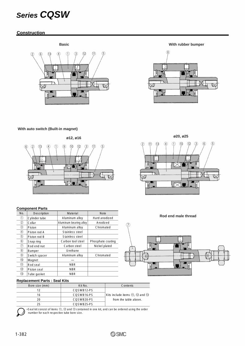
w y !3 r q e !2 !1 t i
tye!2!0qr!3!1wt!1!2!0oqr!3wy e
Basic
With auto switch (Built-in magnet)
With rubber bumper
ø20, ø25ø12, ø16
Component PartsNo.
q
w
e
r
t
y
u
i
o
!0
!1
!2
!3
Description
Replacement Parts : Seal Kits
Material
Aluminum alloy
Aluminum bearing alloy
Aluminum alloy
Stainless steel
Stainless steel
Carbon tool steel
Carbon steel
Urethane
Aluminum alloy
—
NBR
NBR
NBR
Note
Hard anodized
Anodized
Chromated
Phosphate coating
Nickel plated
Chromated
Cylinder tube
Collar
Piston
Piston rod A
Piston rod B
Snap ring
Rod end nut
Bumper
Switch spacer
Magnet
Rod seal
Piston seal
Tube gasket
Bore size (mm)
12
16
20
25
Kit No.
CQSWB12-PS
CQSWB16-PS
CQSWB20-PS
CQSWB25-PS
Contents
Kits include items !1, !2 and !3
from the table above.
∗Seal kit consist of items !1, !2 and !3 contained in one kit, and can be ordered using the order number for each respective tube bore size.
u
Rod end male thread
Series CQSW
Construction
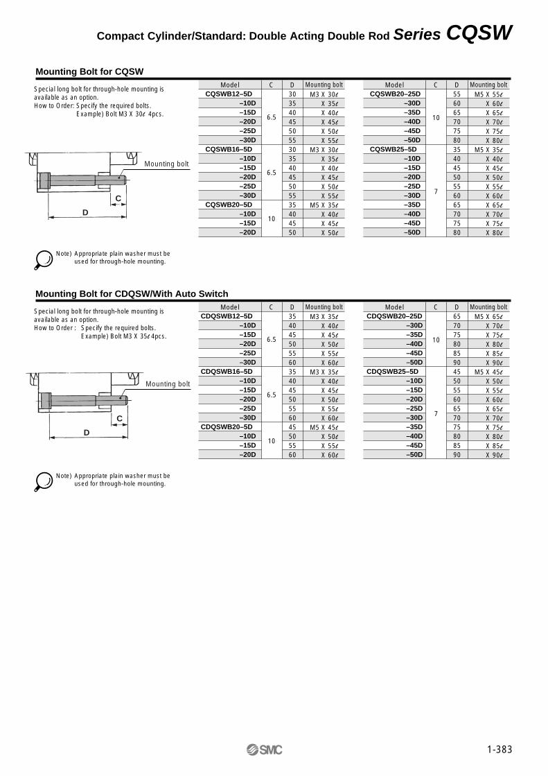
CQSWB12–5D–10D–15D–20D–25D–30D
CQSWB16–5D–10D–15D–20D–25D–30D
CQSWB20–5D–10D–15D–20D
Model C
6.5
6.5
10
D30354045505530354045505535404550
Mounting boltM3 X 30l
X 35l
X 40l
X 45l
X 50l
X 55l
M3 X 30l
X 35l
X 40l
X 45l
X 50l
X 55l
M5 X 35l
X 40l
X 45l
X 50l
CQSWB20–25D–30D–35D–40D–45D–50D
CQSWB25–5D–10D–15D–20D–25D–30D–35D–40D–45D–50D
Model C
10
7
D55606570758035404550556065707580
Mounting boltM5 X 55l
X 60l
X 65l
X 70l
X 75l
X 80l
M5 X 35l
X 40l
X 45l
X 50l
X 55l
X 60l
X 65l
X 70l
X 75l
X 80l
Mounting Bolt for CQSW
Special long bolt for through-hole mounting is available as an option.How to Order: Specify the required bolts. Example) Bolt M3 X 30l 4pcs.
Note) Appropriate plain washer must be used for through-hole mounting.
CDQSWB12–5D–10D–15D–20D–25D–30D
CDQSWB16–5D–10D–15D–20D–25D–30D
CDQSWB20–5D–10D–15D–20D
Model C
6.5
6.5
10
D35404550556035404550556045505560
Mounting boltM3 X 35l
X 40l
X 45l
X 50l
X 55l
X 60l
M3 X 35l
X 40l
X 45l
X 50l
X 55l
X 60l
M5 X 45l
X 50l
X 55l
X 60l
CDQSWB20–25D–30D–35D–40D–45D–50D
CDQSWB25–5D–10D–15D–20D–25D–30D–35D–40D–45D–50D
Model C
10
7
D65707580859045505560657075808590
Mounting boltM5 X 65l
X 70l
X 75l
X 80l
X 85l
X 90l
M5 X 45l
X 50l
X 55l
X 60l
X 65l
X 70l
X 75l
X 80l
X 85l
X 90l
Mounting Bolt for CDQSW/With Auto Switch
Special long bolt for through-hole mounting is available as an option.How to Order : Specify the required bolts.
Example) Bolt M3 X 35l 4pcs.
Note) Appropriate plain washer must be used for through-hole mounting.
1-383
C
D
Mounting bolt
C
D
Mounting bolt
Compact Cylinder/Standard: Double Acting Double Rod Series CQSW
1-384
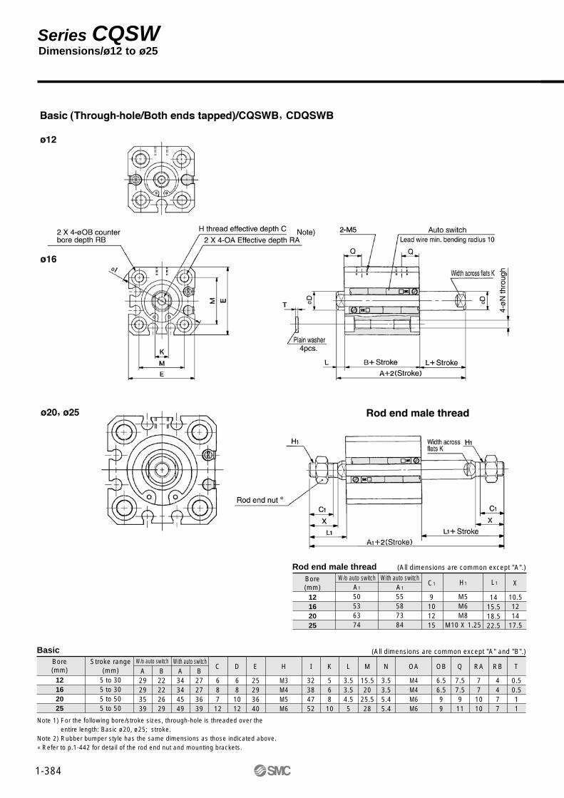
Note 1) For the following bore/stroke sizes, through-hole is threaded over the entire length: Basic ø20, ø25; stroke.
Note 2) Rubber bumper style has the same dimensions as those indicated above.∗ Refer to p.1-442 for detail of the rod end nut and mounting brackets.
Rod end male thread
12162025
Bore(mm)
W/o auto switchA1
50536374
With auto switchA1
55587384
C1
9101215
H1
M5M6M8
M10 X 1.25
L1 X
10.51214
17.5
1415.518.522.5
BasicBore(mm)
Stroke range(mm) A
29293539
B22222629
A34344549
B27273639
C
687
12
D
68
1012
E
25293640
H
M3M4M5M6
I
32384752
K
56810
L
3.53.54.55
M
15.520
25.528
N
3.53.55.45.4
OA
M4M4M6M6
OB
6.56.599
Q
7.57.5911
RA
771010
RB
4477
T
0.50.511
12162025
5 to 305 to 305 to 505 to 50
W/o auto switch With auto switch(All dimensions are common except "A" and "B".)
(All dimensions are common except "A".)
Dimensions/ø12 to ø25 Series CQSW

1-385
Foot (All dimensions are common except "A", "A1", "B" and "LS".)
Bore(mm)
12162025
Stroke range(mm)
5 to 305 to 305 to 505 to 50
A49495559
A170738394
B22222629
LS10101414
A54546569
A1757893
104
B27273639
LS15152424
L
13.513.514.515
L1
2425.528.532.5
LD
4.54.56.66.6
LG
2.82.844
LH
17192426
LT
22
3.23.2
LX
34384852
LY
29.533.54246
LZ
44486266
X
88
9.210.7
Y
4.55
5.85.8
With auto switchWithout auto switch
Flange (All dimensions are common except "A", "A1" and "B".)
Bore(mm)
12162025
Stroke range(mm)
5 to 305 to 305 to 505 to 50
A39394549
A160637384
B22222629
A44445559
A165688394
B27273639
FD
4.54.56.66.6
FT
5.55.588
FV
25303942
FX
45454852
FZ
55556064
L
13.513.514.515
L1
3.53.54.55
L2
2425.528.532.5
L3
1415.518.522.5
With auto switchWithout auto switch
∗ Refer to p.1-442 for detail of the rod end nut and mounting brackets.
Compact Cylinder/Standard: Double Acting Double Rod Series CQSW

CQS
CDQS
B
B
20
20
10
10
S
S
24V5V
12V100V
≤
100V12V
5V
12V24V
A90V
A93V
A96V
M9NV
M9PV
M9BV
M9NWV
M9PWV
M9BWV
A90
A93
A96
Mounting Bracket Part No.Bore size
(mm)
12
16
20
25
CQS-L012
CQS-L016
CQS-L020
CQS-L025
CQS-F012
CQS-F016
CQS-F020
CQS-F025
CQS-D012
CQS-D016
CQS-D020
CQS-D025
ST
Single acting spring returnSingle acting spring extend
—M
Standard (Rod end female thread)Rod end male thread
BLFGD
12162025
12mm16mm20mm25mm
Standard strokeBore size (mm)
5, 10
Standard stroke (mm)
12, 16, 20, 25
Note 1) 2 pieces per cylinder should be ordered.Note 2) Each package contains the following parts.
Foot or Flange style: Body mounting boltDouble clevis: Clevis pin, snap ring retainer, body mounting bolt.
With auto switch
Standard
With auto switch(Built-in magnet)
Mounting styleThrough-hole/Both ends tapped (Standard)
FootFront flangeRear flange
Double clevis
Bore size
Cylinder stroke (mm)
Action
Option
Foot(1)
Flange Double clevis
Indi
cato
r Load voltage
DC AC
Auto switch model
Perpendicular In-line
Lead wire (m)∗
0.5(—)
3(L)
5(Z)
Ree
d sw
itch
Sol
id s
tate
sw
itch
Applicableload
SpecialfunctionStyle
Elec-tricalentry
Wiring(Output)
Diagnosticindication(2 colour)
Grommet
Grommet
Yes
NoY
es
2 wire
3 wire(Equiv.NPN)
3 wire(NPN)
3 wire(PNP)
2 wire
3 wire(NPN)
3 wire(PNP)
2 wire
IC
IC
RelayPLC
RelayPLC
∗ Lead wire length
∗ Solid state switches marked with a " " are manufactured upon receipt of order.
0.5m ·········· — (Example) A933m ·········· L (Example) A93L5m ·········· Z (Example) M9NWZ
Applicable Auto Switches
—
S
n
2
1
n
A90 S
∗ Refer to table below for auto switch model No.
— Without auto switch (Built-in magnet)
Auto switch
Number of auto switches
∗ Mounting brackets are shipped not assembled with the cylinder.
1-386
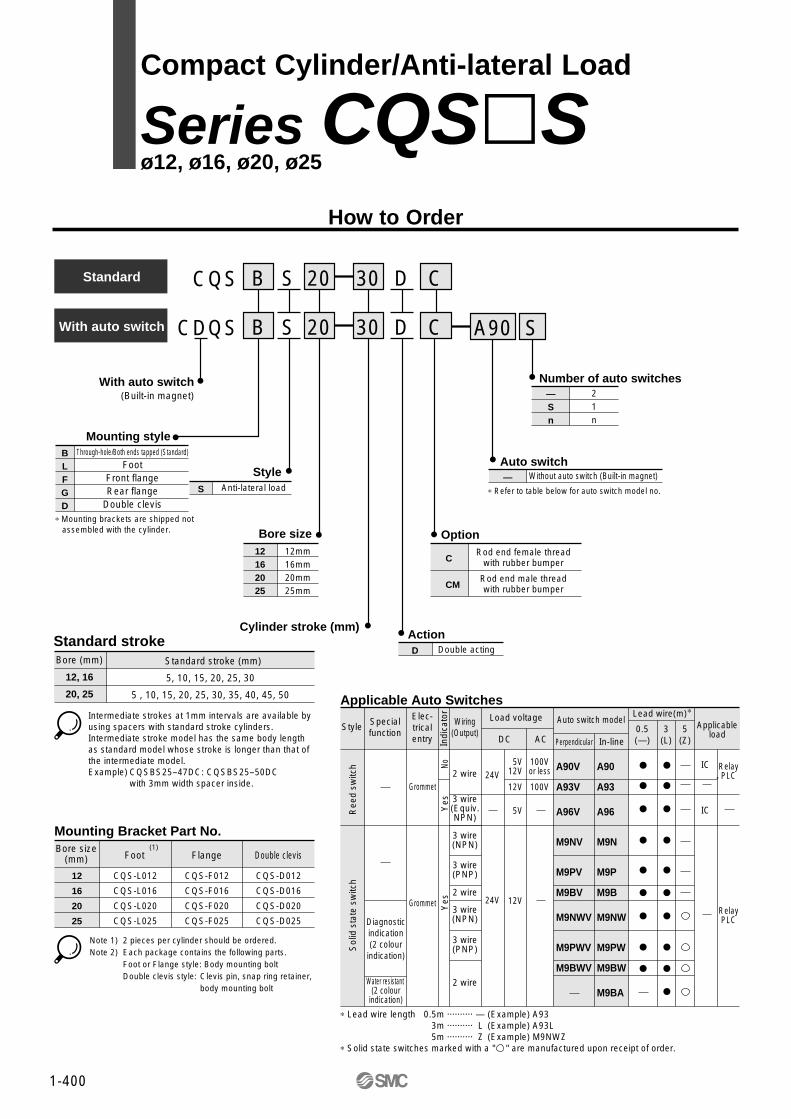
Compact Cylinder/Standard: Single Acting Spring Return/Extend
Series CQS ø12, ø16, ø20, ø25
How to Order

Min. Operating Pressure Unit: MPa
Bore size (mm)
Min. operating pressure
12
0.25
16
0.25
20
0.18
25
0.18
Available for all standard models of single acting single rod.
OptionOption
Rod end male thread
Availability
Allowable Kinetic Energy Unit: J
Bore size (mm)
Standard
Rubber bumper
12
0.022
0.043
16
0.038
0.075
20
0.055
0.11
25
0.09
0.18
Snap Ring Installation/Removal
Caution
q For installation and removal, use an appropriate pair of pliers(Tool for installing a C snap ring).
w Exercise caution even when using an appropriate pair of pliers because of the possibility ofthe snap ring becoming detached from the tip of the pliers and flying away, which could injure humans or damage the peripheral equipment. After installing the snap ring, make sure that it is placed securely in the ring groove before supplying air.
Standard Specifications
Note 1) Consult SMC for shorter stroke length than indicated in the table.
Minimum Strokes for Auto Switch Mounting Unit: mm
No. of auto switches
2
1
D-A9�, D-M9�WV
10
10 (1)
D-A9�V
10
5
D-M9�V
5
5
Theoretical Force Unit: N
Weight/Without Auto SwitchSpring return (Spring extend) Unit: g
Bore size(mm)
Stroke (mm)
12
16
20
25
5
29(31)
39(39)
63(68)
92(98)
10
36(37)
48(47)
76(79)
108(113)
Weight/With Auto Switch (Built-in magnet)Spring return (Spring extend) Unit: g
Bore size(mm)
Stroke (mm)
12
16
20
25
5
37(39)
49(51)
94(104)
130(150)
10
44(45)
58(59)
107(115)
146(165)
Option Weights Unit: g
Male thread
NutRod end male thread
Foot (including bolt)
Front flange (including bolt)
Rear flange (including bolt)
Double clevis (including pin, snap ring, bolt)
Bore size (mm)
1.5
1
55
58
56
34
12
3
2
65
70
66
40
16
6
4
159
143
137
92
20
12
8
181
180
171
127
25
ActionBoresize(mm)
OperationPistonarea
(mm2)Beginning Ending
Roddiameter
(mm)
Operating press (MPa)
Spr
ing
retu
rnS
prin
g ex
tend
12
16
20
25
12
16
20
25
6
8
10
12
6
8
10
12
20
45
78
126
14
24
44
84
43
86
141
224
31
54
91
160
65
126
204
323
48
85
138
235
14
15
15
21
10
19
27
29
4
6
6
11
3
4
5
10
IN
OUT
IN
OUT
IN
OUT
IN
OUT
IN
OUT
IN
OUT
IN
OUT
IN
OUT
—
113
—
201
—
314
—
491
84.8
—
151
—
236
—
378
—
0.3 0.5 0.7
∗( ): Spring extend ∗( ): Spring extend
Pneumatic (Non-lube)
Single acting, single rod
Air
1.5MPa
1.0MPa
Without auto switch: –10°C to 70°C (No freezing)
With auto switch: –10°C to 60°C (No freezing)
None
Female thread
JIS Class 2
Through hole/Both ends tapped
50 to 500mm/s
Style
Action
Fluid
Proof pressure
Max. operating pressure
Ambient and fluid temperature
Rubber bumper
Rod end nut
Tolerance of rod end thread
Tolerance of stroke length
Mounting
Operating piston speed
0+1.0
Example) CQSG16-10S• Cylinder weight: CQSB16-10S········································48g : Rear flange···········································66g
Total 114g 1-387
Compact Cylinder/Standard: Single Acting Spring Return/Extend Series CQS

1-388
Component PartsNo.
q
w
e
r
t
y
u
i
o
!0
!1
!2
!3
!4
Description
Replacement Parts: Seal Kits Replacement Parts: Seal Kits
12
16
20
25
CQSB12-S-PS
CQSB16-S-PS
CQSB20-S-PS
CQSB25-S-PS
Kits include item !3
from the table above.
Material
Aluminum alloy
Aluminum bearing alloy
Aluminum alloy
Stainless steel
Stainless steel
Carbon tool steel
Carbon tool steel
Carbon steel
Aluminum alloy
Piano wire
Alloy steel
—
NBR
NBR
NBR
Note
Hard anodized
Anodized
Spring return
Spring extend
Phosphate coating
Nickel plated
Nickel plated
Chromated
Zinc chromated
Nickel plated
Cylinder tube
Collar
Piston
Piston rod
Snap ring
Snap ring
Rod end nut
Switch spacer
Return spring
Plug with fixed orifice
Magnet
Rod seal
Piston seal
Tube gasket
Bore size (mm) Kit No. ContentsAction
Single actingSpring return
12
16
20
25
CQSB12-T-PS
CQSB16-T-PS
CQSB20-T-PS
CQSB25-T-PS
Kits include items!2, !3 and !4
from the table above.
Bore size (mm) Kit No. ContentsAction
Single actingSpring extend
∗ Seal kits consist of item !3 contained in one kit, and can be ordered using the kit number for each respective tube bore size.
∗ Seal kits consist of items !2, !3 and !4 contained in one kit, and can be ordered using the kit number for each respective tube bore size.
∗
∗
∗
w t !0 r o !3 q e w t !2 !4 !3 e !0 q o
!2 t w !4 y i !1 !3 e !0 q o
w t !2 !4 !1 !3 e !0 q ow t !0 r o q !1 !3 e
t w !0 r q o i !1 !3 e
Series CQS
Construction
u u
Single acting/Spring return
Single acting/Spring return/With auto switch (Built-in magnet)ø12, ø16
ø20, 25
Single acting/Spring extend
Single acting/Spring extend/With auto switch (Built-in magnet)
Rod end nut
Spring return Spring extend

CQSB12–5S–10S
CQSB16–5S–10S
CQSB20–5S–10S
CQSB25-5S–10S
Model C
6.5
6.5
6.5
8.5
D2530253025303035
Mounting boltM3 X 25l
X 30l
M3 X 25l
X 30l
M5 X 25l
X 30l
M5 X 30l
X 35l
Note) The appropriate plain washer must be used for through-hole mounting.
Mounting Bolt for CQS
Special long bolt for through-hole mounting is available as an optionHow to Order: Specify the required bolts
Example) Bolt M3 X 25l 4pcs.
Single acting/Spring return
CQSB12–5T–10T
CQSB16–5T–10T
CQSB20–5T–10T
CQSB25–5T–10T
Model C
6.5
6.5
6.5
8.5
D2530253025303035
Mounting boltM3 X 25l
X 30l
M3 X 25l
X 30l
M5 X 25l
X 30l
M5 X 30l
X 35l
Single acting/Spring extend
CDQSB12–5S –10S
CDQSB16–5S –10S
CDQSB20–5S –10S
CDQSB25–5S –10S
Model C
6.5
6.5
6.5
8.5
D3035303535404045
Mounting boltM3 X 30l
X 35l
M3 X 30l
X 35l
M5 X 35l
X 40l
M5 X 40l
45l
Note) The appropriate plain washer must be used for through-hole mounting.
Mounting Bolt for CDQS
Special long bolt for through-hole mounting is available as an optionHow to Order: Specify the required bolts
Example) Bolt M3 X 30l 4pcs.
Single acting/Spring return
CDQSB12–5T –10T
CDQSB16–5T –10T
CDQSB20–5T –10T
CDQSB25–5T –10T
Model C
6.5
6.5
6.5
8.5
D3035303535404045
Mounting boltM3 X 30l
X 35l
M3 X 30l
X 35l
M5 X 35l
X 40l
M5 X 40l
X 45l
Single acting/Spring extend
1-389
Compact Cylinder/Standard: Single Acting Spring Return/Extend Series CQS

1-390
Rod end male threadBore (mm)
12162025
C1
9101215
H1
M5M6M8
M10 X 1.25
L1
1415.518.522.5
X10.51214
17.5
Basic
Bore(mm)
Stroke range(mm)
5ST
25.525.529
32.5
10ST
30.530.534
37.5
5ST
2222
24.527.5
10ST
2727
29.532.5
5ST
30.530.539
42.5
10ST
35.535.544
47.5
5ST
2727
34.537.5
10ST
3232
39.542.5
C
68712
D
681012
E
25293640
F
55
5.55.5
H
M3M4M5M6
I
32384752
K
56810
L
3.53.54.55
M
15.520
25.528
N
3.53.55.45.4
OA
M4M4M6M6
OB
6.56.599
RA
771010
RB
4477
T
0.50.511
12162025
5, 10
A B A BWithout auto switch With auto switch
(All dimensions are common expect "A" and "B".)
Note) Basic: For the following bore/stroke sizes, through-hole is threaded over the entire length. ø12 and ø16; 5 stroke, ø20 and ø25; 5 to 10 stroke(With auto switch (Built-in magnet): ø20; 5 stroke
∗ Refer to p.1-442 for details of the rod end nut and mounting brackets.
Dimensions/ø12 to ø25: Spring Return Series CQS
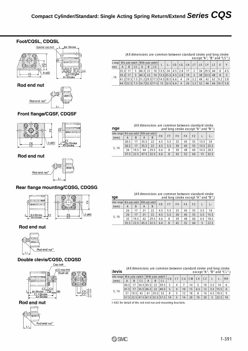
Foot(All dimensions are common between standard stroke and long stroke
except "A", "B" and "LS".)Bore(mm)
12162025
Stroke range(mm)
5, 10
W/o auto switchA
35.335.341.244.7
B1717
19.522.5
LS55
7.57.5
With auto switchA
40.340.351.254.7
B2222
29.532.5
LS1010
17.517.5
L
13.513.514.515
L1
2425.528.532.5
LD
4.54.56.66.6
LG
2.82.844
LH
17192426
LT
22
3.23.2
LX
34384852
LY
29.533.54246
LZ
44486266
X
88
9.210.7
Y
4.55
5.85.8
Front flange(All dimensions are common between standard stroke
and long stroke except "A" and "B".)Bore(mm)
12162025
Stroke range(mm)
5, 10
W/o auto switchA
30.530.534
37.5
B1717
19.522.5
With auto switchA
35.535.544
47.5
B2222
29.532.5
FD
4.54.56.66.6
FT
5.55.588
FV
25303942
FX
45454852
FZ
55556064
L
13.513.514.515
L1
2425.528.532.5
Rear flange(All dimensions are common between standard stroke
and long stroke except "A" and "B".)Bore(mm)
12162025
Stroke range(mm)
5, 10
W/o auto switchA262632
35.5
B1717
19.522.5
With auto switchA313142
45.5
B2222
29.532.5
FD
4.54.56.66.6
FT
5.55.588
FV
25303942
FX
45454852
FZ
55556064
L
3.53.54.55
L1
1415.518.522.5
∗ Refer to P.1-442 for detail of the rod end nut and mounting brackets.
Double clevis(All dimensions are common between standard stroke and long stroke
except "A", "B" and "CL".)Bore(mm)
12162025
Stroke range(mm)
5, 10
W/o auto switch With auto switchA
40.541.551
57.5
B1717
19.522.5
CL34.535.542
47.5
A45.546.561
67.5
B2222
29.532.5
CL39.540.552
57.5
CD
558
10
CT
4455
CU
7101214
CW
14151820
CX
56.58
10
CZ
10121620
L
3.53.54.55
L1
1415.518.522.5
RR
66910
1-391
Compact Cylinder/Standard: Single Acting Spring Return/Extend Series CQS
1-392
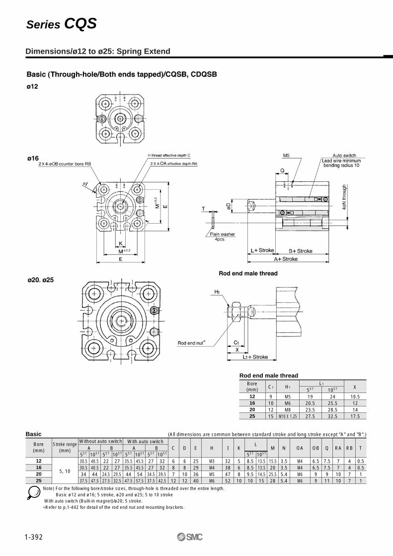
Rod end male thread
12162025
Bore(mm) C1
9101215
H1
M5M6M8
M10 X 1.25
5ST
1920.523.527.5
10ST
2425.528.532.5
X
10.51214
17.5
Basic
Bore(mm)
Stroke range(mm)
5ST
30.530.53437.5
10ST
40.540.544
47.5
5ST
222224.527.5
10ST
272729.532.5
5ST
35.535.54447.5
10ST
45.545.55457.5
5ST
272734.537.5
10ST
323239.542.5
C
68712
D
681012
E
25293640
H
M3M4M5M6
I
32384752
K
56810
10ST
13.513.514.515
5ST
8.58.59.510
M
15.52025.528
N
3.53.55.45.4
OA
M4M4M6M6
OB
6.56.599
Q
7.57.5911
RA
771010
RB
4477
T
0.50.511
12162025
5, 10
A B A BWithout auto switch With auto switch
(All dimensions are common between standard stroke and long stroke except "A" and "B".)
L1
L
Note) For the following bore/stroke sizes, through-hole is threaded over the entire length. Basic ø12 and ø16; 5 stroke, ø20 and ø25; 5 to 10 stroke With auto switch (Built-in magnet)/ø20; 5 stroke.∗Refer to p.1-442 for detail of the rod end nut and mounting brackets.
Dimensions/ø12 to ø25: Spring Extend
Series CQS
5, 10
Foot (All dimensions are common between standard stroke and long stroke except "A", "B" and "LS".)
(All dimensions are common between standard stroke and long stroke except "A", "B" and "CL".)
(All dimensions are common between standard stroke and long stroke except "A" and "B".)
(All dimensions are common between standard stroke and long stroke except "A" and "B".)
Bore(mm)
Bore(mm)
Stroke range(mm)
12162025
12162025
Without auto switch With auto switch
Bore(mm)
Bore(mm)
Bore(mm)
Bore(mm)
Stroke range(mm)
Stroke range(mm)
Stroke range(mm)
W/o auto switch
W/o auto switch
Without auto switch
With auto switch
With auto switch
With auto switch
A35.335.341.244.7
B1717
19.522.5
LS55
7.57.5
A40.340.351.254.7
B2222
29.532.5
LS1010
17.517.5
L
13.513.514.515
L1
2425.528.532.5
LD
4.54.56.66.6
LG
2.82.844
LH
17192426
LT
22
3.23.2
LX
34384852
LY
29.533.54246
LZ
44486266
X
88
9.210.7
Y
4.55
5.85.8
5, 10
12162025
A262632
35.5
B1717
19.522.5
A313142
45.5
B2222
29.532.5
FD
4.54.56.66.6
FT
5.55.588
FV
25303942
FX
45454852
FZ
55556064
L
3.53.54.55
L1
1415.518.522.5
Rear flange
5, 10
12162025
A30.530.534
37.5
B1717
19.522.5
A35.535.544
47.5
B2222
29.532.5
FD
4.54.56.66.6
FT
5.55.588
FV
25303942
FX
45454852
FZ
55556064
L
13.513.514.515
L1
2425.528.532.5
Front flange
5, 10
Double clevis
12162025
A40.541.551
57.5
B1717
19.522.5
CL34.535.542
47.5
A45.546.561
67.5
B2222
29.532.5
CL39.540.552
57.5
12162025
CD
55810
CT
4455
CU
7101214
CW
14151820
CX
56.5810
CZ
10121620
L
3.53.54.55
L1
1415.518.522.5
RR
669
10
∗Refer to p.1-442 for detail of the rod end nut and mounting brackets.
1-393
Compact Cylinder/Standard: Single Acting Spring Return/Extend Series CQS

CQSK
CDQSK
B
B
20
20
30
30
D
D
Mounting Bracket Part No.Bore size
(mm)
12
16
20
25
CQSK-L012
CQSK-L016
CQSK-L020
CQSK-L025
CQSK-F012
CQSK-F016
CQSK-F020
CQSK-F025
CQSK-D012
CQSK-D016
CQSK-D020
CQSK-D025
D Double acting
—M
Standard (Rod end female thread)Rod end male thread
BLFGD
Through-hole/Both ends tapped (Standard)
FootFront flangeRear flange
Double clevis
12162025
12mm16mm20mm25mm
Double acting double rod model is now available.Consult SMC for the detail.
Standard strokeBore (mm)
5 , 10, 15, 20, 25, 30
5 , 10, 15, 20, 25, 30, 35, 40, 45, 50
Standard stroke (mm)
12, 16
20, 25
24V5V
12V100Vor less
100V12V
5V
12V24V
A90V
A93V
A96V
M9NV
M9PV
M9BV
M9NWV
M9PWV
M9BWV
A90
A93
A96
M9N
M9P
M9B
M9NW
M9PW
M9BW
M9BA
Intermediate strokes at 1mm intervals are available by using spacers with standard stroke sylinders. Intermediate stroke model has the same body length as standard model whose stroke is longer than that of the intermediate model.Example) CQSKB25–47D: CQSKB25–50D
with 3mm width spacer inside.
Note 1) 2 pieces per cylinder should be ordered.Note 2) Each package contains the following parts.
Foot or Flange style: Body mounting boltDouble clevis style: Clevis pin, snap ring retainer,
body mounting bolt.
IC
IC
RelayPLC
RelayPLC
Indi
cato
r Load voltage
DC AC
Auto switch model
Perpendicular In-line
Lead wire (m)∗
0.5(—)
3(L)
5(Z)
Ree
d sw
itch
Sol
id s
tate
sw
itch
Applicableload
Specialfunction
StyleElec-tricalentry
Wiring(Output)
Diagnosticindication(2 colour)
Waterresistant(2 colour)
Grommet
Grommet
Yes
NoY
es
2 wire
3 wire(Equiv.NPN)
3 wire(NPN)
3 wire(PNP)
2 wire
3 wire(NPN)
3 wire(PNP)
2 wire
∗ Lead wire length
∗ Solid state switches marked with a " " are manufatured upon receipt of order.
0.5m ·········· — (Example) A933m ·········· L (Example) A93L5m ·········· Z (Example) M9NWZ
Applicable Auto Switch
With auto switch
Standard
With auto switch(Built-in magnet)
Mounting style
Bore size
Cylinder stroke (mm)
Foot(1)
Flange Double clevis
Action
Option
—
S
n
2
1
n
A90 S
∗ Refer to table below for auto switch model no.
— Without auto switch (Built-in magnet)
Number of auto switches
Auto switch
∗ Mounting brackets are shipped not assembled with the cylinder.
1-394
Compact Cylinder/Non-rotating Rod: Double Acting Single Rod
Series CQSK ø12, ø16, ø20, ø25
How to Order

Minimum Operating Pressure Unit: MPa
Bore size (mm)
Min. operating pressure
12
0.07
16
0.07
20
0.05
25
0.05
Allowable Kinetic Energy Unit: J
Bore size (mm)
Kinetic energy
12
0.022
16
0.038
20
0.055
25
0.09
Rod Non-rotating SpecificationsBore size (mm)
Rod non-rotating accuracy
12 16 20 25
Available for all non-rotating rod models.
OptionDescription
Rod end male thread
Availability
±1° ±0.7°
Pneumatic(Non-lube)
Double acting Single rod
Air
1.5MPa
1.0MPa
Without auto switch –10°C to 70°C (No freezing)
With auto switch –10°C to 60°C (No freezing)
None
Female thread
JIS Class 2
Through-hole/Both ends tapped
50 to 500mm/s
Standard SpecificationsStyle
Operating type
Fluid
Proof pressure
Max. operating pressure
Ambient and fluid temperature
Rubber bumper
Rod end nut
Tolerance of rod end thread
Stroke length tolerance
Mounting
Piston speed
0
Theoretical Force Unit: N
Bore size(mm)
12
16
20
25
Rod widthacross flats
(mm)
5.2
6.2
8.2
10.2
Action
IN
OUT
IN
OUT
IN
OUT
IN
OUT
Piston area(mm2)
90
113
168
201
256
314
401
491
Operating pressure (MPa)
0.3
27
34
50
60
77
94
120
147
0.5
45
57
84
101
128
157
200
245
0.7
63
79
117
141
179
220
281
344
Weight/Without Auto Switch Unit: g
Bore size(mm)
12
16
20
25
Stroke (mm)
5
39
52
89
124
10
46
61
102
141
15
53
69
116
157
20
60
78
129
174
25
67
86
143
190
30
74
95
156
207
35
—
—
170
224
40
—
—
183
240
45
—
—
197
257
50
—
—
211
273
Weight/With Auto Switch (Built-in magnet) Unit: g
12
16
20
25
Stroke (mm)
5
47
63
122
168
10
54
71
136
185
15
62
80
149
201
20
69
88
163
218
25
76
97
176
235
30
83
106
190
251
35
—
—
203
268
40
—
—
217
284
45
—
—
230
301
50
—
—
244
317
Option Weights Unit: g
Male thread
NutRod end male thread
Foot (including bolt)
Front flange (including bolt)
Rear flange (including bolt)
Double clevis (including pin, snap ring, bolt)
Bore size (mm)
1.5
1
55
58
56
34
+1.0
12
3
2
64
69
66
40
16
6
4
158
142
137
92
20
12
8
179
178
171
127
25
OUT IN
Bore size(mm)
∗ Consult SMC for shorter stroke length than indicated in the table.
Minimum Strokes for Auto Switch Mounting Unit: mm
No. of auto switches
2
1
D-A9�, D-M9�WV
10
10∗
D-A9�V
10
5
D-M9N
15∗
15
D-M9 , D-M9�W
20∗
20∗
D-M9�V
5
5
D-M9BA
25∗
25∗
BP
Snap Ring Installation/Removal
Caution
q For installation and removal, use an appropriate pair of pliers(tool for installing a C type snap ring).
w Exercise caution even when using an appropriate pair of pliersbecause of the possibility of the snap ring becoming detached from the tip of thepliers and flying away, which could injurehumans or damage the peripheralequipment. After installing the snap ring,make sure that it is placed securely in thering groove before supplying air.
Calculation Example) CQSKF20-5DM• Cylinder weight: CQSKB20-5D············································89g• Option weight: Rod end male thread···································10g : Front flange················································142g
Total 241g
1-395
Compact Cylinder/Non-rotating Rod: Double Acting Single Rod Series CQSK

Component PartsDescription Material
Aluminum alloy
Aluminum alloy (1)
Aluminum alloy
Stainless steel
Aluminum alloy
Oil impregnated sintered alloy
Alloy steel
Rolled steel
Carbon steel
NBR
NBR
NBR
Note
Hard anodized
Anodized
Chromated
Chromated
ø16, ø20 and ø25
Nickel plated
Nickel plated
Nickel plated
Cylinder tube
Rod cover
Piston
Piston rod
Switch spacer
Magnet
Ron rotating guide
Hex. socket head cap screw
Plain washer
Rod end nut
Rod seal
Piston seal
Tube gasketNote 1) ø12: Aluminum bearing alloy.
Replacement Parts: Seal Kits
12
16
20
25
CQSKB12-PS
CQSKB16-PS
CQSKB20-PS
CQSKB25-PS
Kits include items !1, !2 and !3from the table above.
Bore size (mm) Kit No. Contents
∗Seal kits consist of items !1, !2 and !3 contained in one kit, and can be ordered using the order number for each respective tube bore size.
Allowable rotationtorque Nm
ø120.04
ø160.04
ø200.2
ø250.25
Precautions
qAny kind of operation producing rotation torque to piston rod must be considered.
The non-rotating guide would be deformed and the accuracy would be compromised. See the table below for rotation torque allowance.
Caution
wLoad to piston rod must always be in an axial direction.eWhen fixing work piece to piston rod end, completely retract the
rod before applying any kind of torque. Prevent torque on the guide bushing by holding the rod stationary with a wrench. Do not apply torque directly to the rod.
Construction
No.
q
w
e
r
t
y
u
i
o
!0
!1
!2
!3
∗
∗
∗
1-396
Series CQSK

Special long bolt for through hole mounting is available as an option.How to Order: Specify the required bolts.
Example) Bolt M3 X 30l 2pcs.
Mounting Bolt for CQSK
Note) The appropriate plain waher must be used for through-hole.
Model C D2530354045502530354045502530354045505560657030354045505560657075
Mounting bolt Mounting bolt CQSKB12–5D
–10D–15D–20D–25D–30D
CQSKB16–5D–10D–15D–20D–25D–30D
CQSKB20–5D–10D–15D–20D–25D–30D–35D–40D–45D–50D
CQSKB25–5D–10D–15D–20D–25D–30D–35D–40D–45D–50D
6.5
6.5
6.5
8.5
M3 X 25 lX 30 lX 35 lX 40 lX 45 lX 50 l
M3 X 25 lX 30 lX 35 lX 40 lX 45 lX 50 l
M5 X 25 lX 30 lX 35 lX 40 lX 45 lX 50 lX 55 lX 60 lX 65 lX 70 l
M5 X 30 lX 35 lX 40 lX 45 lX 50 lX 55 lX 60 lX 65 lX 70 lX 75 l
C' D'3035404550553035404550553035404550556065707535404550556065707580
6.5
6.5
6.5
8.5
M3 X 30 lX 35 lX 40 lX 45 lX 50 lX 55 l
M3 X 30 lX 35 lX 40 lX 45 lX 50 lX 55 l
M5 X 30 lX 35 lX 40 lX 45 lX 50 lX 55 lX 60 lX 65 lX 70 lX 75 l
M5 X 35 lX 40 lX 45 lX 50 lX 55 lX 60 lX 65 lX 70 lX 75 lX 80 l
Special long bolt for through hole mounting isavailable as an option.How to Order: Specify the required bolts.
Example) Bolt M3 X 35l 2pcs.
Mounting Bolt for CDQSK
Note) The appropriate plain washer must be used for through-hole.
Model C D3035404550553035404550553540455055606570758040455055606570758085
Mounting bolt Mounting bolt CDQSKB12–5D
–10D –15D –20D –25D –30D
CDQSKB16–5D –10D –15D –20D –25D –30D
CDQSKB20–5D –10D –15D –20D –25D –30D –35D –40D –45D –50D
CDQSKB25–5D –10D –15D –20D –25D –30D –35D –40D –45D –50D
6.5
6.5
6.5
8.5
M3 X 30 lX 35 lX 40 lX 45 lX 50 lX 55 l
M3 X 30 lX 35 lX 40 l X 45 lX 50 lX 55 l
M5 X 35 lX 40 lX 45 lX 50 lX 55 lX 60 lX 65 lX 70 lX 75 lX 80 l
M5 X 40 lX 45 lX 50 lX 55 lX 60 lX 65 lX 70 lX 75 lX 80 lX 85 l
C' D'3540455055603540455055604045505560657075808545505560657075808590
6.5
6.5
6.5
8.5
M3 X 35 lX 40 l X 45 lX 50 lX 55 lX 60 l
M3 X 35 lX 40 lX 45 lX 50 lX 55 lX 60 l
M5 X 40 lX 45 lX 50 lX 55 lX 60 lX 65 lX 70 lX 75 lX 80 lX 85 l
M5 X 45 lX 50 lX 55 lX 60 lX 65 lX 70 lX 75 lX 80 lX 85 lX 90 l
1-397
Compact Cylinder/Non-rotating Rod: Double Acting Single Rod Series CQSK

Dimensions/ø12 to ø25
Rod end male threadBore(mm)
12162025
C1
9101215
H1
M5M6M8
M10 X 1.25
L1
1415.518.522.5
X10.51214
17.5
BasicBore(mm)
Stroke range(mm) A
25.525.529
32.5
B2222
24.527.5
A30.530.539
42.5
B2727
34.537.5
C
687
12
E
25293640
F
55
5.55.5
H
M3M4M5M6
I
32384752
K
5.26.28.210.2
L
3.53.54.55
M
15.520
25.528
N
3.53.55.45.4
OA
M4M4M6M6
OB
6.56.599
Q
12.512.51416
RA
771010
RB
4477
T
0.50.511
12162025
5 to 305 to 305 to 505 to 50
W/o auto switch With auto switch(All dimension are common except "A" and "B").
Note)For the following bore/stroke sizes, through hole is threaded over the entire length.Basic: ø12 and ø16; 5 stroke, ø20; 5 to 15 stroke, ø25; 5 and 10 stroke.
Note) With auto switch (Built-in magnet): ø20; 5 stroke∗Refer to p.1-442 for detail of the rod end nut and mounting
brackets.
∗Refer to P.1-408 for mounting position and height of auto switch.
1-398
Series CQSK

Foot(All dimensions are common between standard stroke and long stroke except "A", "B" and "LS".)
Bore(mm)
12162025
Stroke range(mm)
5 to 305 to 305 to 505 to 50
W/o auto switch With auto switchA
40.340.346.249.7
B222224.527.5
LS101012.512.5
A45.345.356.259.7
B272734.537.5
LS151522.522.5
L
13.513.514.515
L1
2425.528.532.5
LD
4.54.56.66.6
LG
2.82.844
LH
17192426
LT
22
3.23.2
LX
34384852
LY
29.533.54246
LZ
44486266
X
88
9.210.7
Y
4.55
5.85.8
Front flange(All dimensions are common between standard stroke and long stroke except "A" and "B".)
Bore(mm)
12162025
Stroke range(mm)
5 to 305 to 305 to 505 to 50
W/o auto switch With auto switchA
35.535.539
42.5
B2222
24.527.5
A40.540.549
52.5
B2727
34.537.5
FD
4.54.56.66.6
FT
5.55.588
FV
25303942
FX
45454852
FZ
55556064
L
13.513.514.515
L1
2425.528.532.5
Rear flange(All dimensions are common between standard stroke and long stroke except "A", and "B".)
Bore(mm)
12162025
Stroke range(mm)
5 to 305 to 305 to 505 to 50
W/o auto switch With auto switchA313137
40.5
B2222
24.527.5
A363647
50.5
B2727
34.537.5
FD
4.54.56.66.6
FT
5.55.588
FV
25303942
FX
45454852
FZ
55556064
L
3.53.54.55
L1
1415.518.522.5
∗Refer to p.1-442 for detail of the rod end nut and mounting brackets.
Double clevis(All dimensions are common between standard stroke and long stroke except "A", "B" and "CL".)
Bore(mm)
12162025
Stroke range(mm)
5 to 305 to 305 to 505 to 50
W/o auto switch With auto switchA
45.546.556
62.5
B2222
24.527.5
CL39.540.547
52.5
A50.551.566
72.5
B2727
34.537.5
CL44.545.557
62.5
CD
558
10
CT
4455
CU
7101214
CW
14151820
CX
56.58
10
CZ
10121620
L
3.53.54.55
L1
1415.518.522.5
RR
66910
1-399
Compact Cylinder/Non-rotating Rod: Double Acting Single Rod Series CQSK
CQS
CDQS
B
B
S
S
20
20
30
30
D
D
C
C
Mounting Bracket Part No.
12
16
20
25
CQS-L012
CQS-L016
CQS-L020
CQS-L025
CQS-F012
CQS-F016
CQS-F020
CQS-F025
CQS-D012
CQS-D016
CQS-D020
CQS-D025
D Double acting
C
CM
Rod end female threadwith rubber bumper
Rod end male threadwith rubber bumper
BLFGD
Through-hole/Both ends tapped (Standard)
FootFront flangeRear flange
Double clevis
12162025
12mm16mm20mm25mm
S Anti-lateral load
Style
Standard strokeBore (mm)
5, 10, 15, 20, 25, 30
5 , 10, 15, 20, 25, 30, 35, 40, 45, 50
Standard stroke (mm)
12, 16
20, 25
Intermediate strokes at 1mm intervals are available by using spacers with standard stroke cylinders. Intermediate stroke model has the same body length as standard model whose stroke is longer than that of the intermediate model.Example) CQSBS25–47DC: CQSBS25–50DC
with 3mm width spacer inside.
Note 1) 2 pieces per cylinder should be ordered.Note 2) Each package contains the following parts.
Foot or Flange style: Body mounting boltDouble clevis style: Clevis pin, snap ring retainer,
body mounting bolt
24V5V
12V100Vor less
100V12V
5V
12V24V
A90V
A93V
A96V
M9NV
M9PV
M9BV
M9NWV
M9PWV
M9BWV
A90
A93
A96
M9N
M9P
M9B
M9NW
M9PW
M9BW
M9BA
With auto switch
Standard
With auto switch(Built-in magnet)
Mounting style
Bore size
Cylinder stroke (mm)
Bore size(mm) Foot
(1)Flange Double clevis
Action
Option
Applicable Auto Switches
Indi
cato
r
Specialfunction
StyleElec-tricalentry
Wiring(Output)
Load voltage
DC AC
Auto switch model
Perpendicular In-line
Lead wire(m)∗
0.5(—)
3(L)
5(Z)
Applicableload
IC
IC
RelayPLC
RelayPLC
Ree
d sw
itch
Sol
id s
tate
sw
itch
Diagnosticindication(2 colour
indication)
Water resistant (2 colour indication)
Grommet
Grommet
Yes
NoY
es
2 wire
3 wire(Equiv.NPN)
3 wire(NPN)
3 wire(PNP)
2 wire
3 wire(NPN)
3 wire(PNP)
2 wire
∗ Lead wire length
∗ Solid state switches marked with a " " are manufactured upon receipt of order.
0.5m ·········· — (Example) A933m ·········· L (Example) A93L5m ·········· Z (Example) M9NWZ
—Sn
21n
A90 S
∗ Refer to table below for auto switch model no.
— Without auto switch (Built-in magnet)Auto switch
Number of auto switches
∗ Mounting brackets are shipped not assembled with the cylinder.
1-400
Compact Cylinder/Anti-lateral Load
Series CQS�Sø12, ø16, ø20, ø25
How to Order
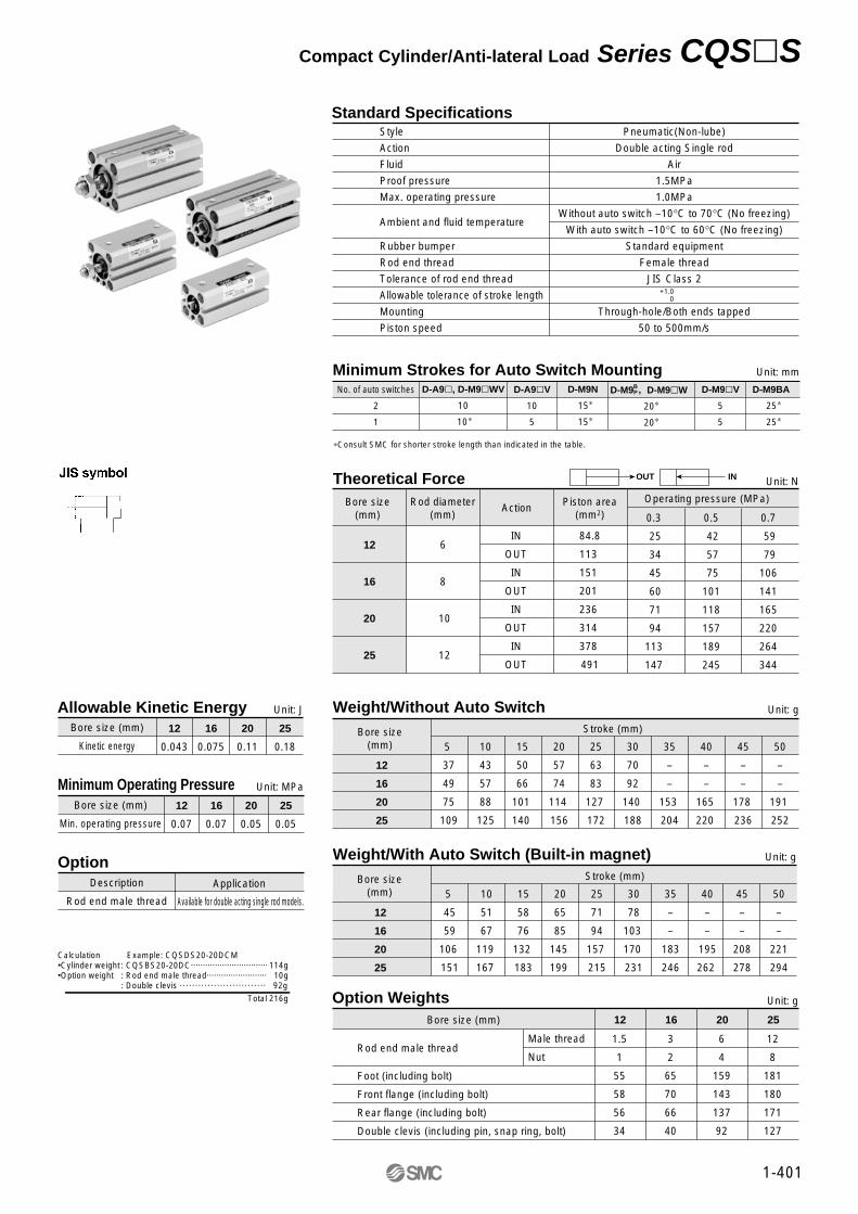
Minimum Operating Pressure Unit: MPa
Bore size (mm)
Min. operating pressure
12
0.07
16
0.07
20
0.05
25
0.05
Available for double acting single rod models.
OptionDescription
Rod end male thread
Application
Calculation Example: CQSDS20-20DCM•Cylinder weight : CQSBS20-20DC································ 114g•Option weight : Rod end male thread························· 10g : Double clevis ···························· 92g
Total 216g
Allowable Kinetic Energy Unit: J
Bore size (mm)
Kinetic energy
12
0.043
16
0.075
20
0.11
25
0.18
Pneumatic(Non-lube)
Double acting Single rod
Air
1.5MPa
1.0MPa
Without auto switch –10°C to 70°C (No freezing)
With auto switch –10°C to 60°C (No freezing)
Standard equipment
Female thread
JIS Class 2
Through-hole/Both ends tapped
50 to 500mm/s
Standard SpecificationsStyle
Action
Fluid
Proof pressure
Max. operating pressure
Ambient and fluid temperature
Rubber bumper
Rod end thread
Tolerance of rod end thread
Allowable tolerance of stroke length
Mounting
Piston speed
Theoretical Force Unit: N
Bore size(mm)
12
16
20
25
Rod diameter(mm)
6
8
10
12
Action
IN
OUT
IN
OUT
IN
OUT
IN
OUT
Piston area(mm2)
84.8
113
151
201
236
314
378
491
Operating pressure (MPa)
0.3
25
34
45
60
71
94
113
147
0.5
42
57
75
101
118
157
189
245
0.7
59
79
106
141
165
220
264
344
Weight/Without Auto Switch Unit: g
Bore size(mm)
12
16
20
25
Stroke (mm)
5
37
49
75
109
10
43
57
88
125
15
50
66
101
140
20
57
74
114
156
25
63
83
127
172
30
70
92
140
188
35
–
–
153
204
40
–
–
165
220
45
–
–
178
236
50
–
–
191
252
Weight/With Auto Switch (Built-in magnet) Unit: g
12
16
20
25
Stroke (mm)
5
45
59
106
151
10
51
67
119
167
15
58
76
132
183
20
65
85
145
199
25
71
94
157
215
30
78
103
170
231
35
–
–
183
246
40
–
–
195
262
45
–
–
208
278
50
–
–
221
294
Option Weights Unit: g
Male thread
NutRod end male thread
Foot (including bolt)
Front flange (including bolt)
Rear flange (including bolt)
Double clevis (including pin, snap ring, bolt)
Bore size (mm)
1.5
1
55
58
56
34
0+1.0
12
3
2
65
70
66
40
16
6
4
159
143
137
92
20
12
8
181
180
171
127
25
Bore size(mm)
OUT IN
∗Consult SMC for shorter stroke length than indicated in the table.
Minimum Strokes for Auto Switch Mounting Unit: mm
No. of auto switches
2
1
D-A9�, D-M9�WV
10
10∗
D-A9�V
10
5
D-M9N
15∗
15∗
D-M9 D-M9�W
20∗
20∗
D-M9�V
5
5
D-M9BA
25∗
25∗
BP ,
1-401
Compact Cylinder/Anti-lateral Load Series CQS�S

Components PartsDescription Material
Aluminum alloy
Aluminum alloy
Aluminum alloy
Stainless steel
Carbon tool steel
Carbon steel
Aluminum alloy
Urethane
Urethane
Oil impregnated sintered alloy
Resin
NBR
NBR
NBR
Note
Hard anodized
Anodized
Chromated
Phosphate coating
Nickel plated
Chromated
Cylinder tube
Collar
Piston
Piston rod
Snap ring
Rod end nut
Awitch spacer
Bumper A
Bumper B
Bushing
Wearing
Magnet
Rod seal
Piston seal
Tube gasket
Replacement Parts: Seal Kits
12
16
20
25
CQSB12-PS
CQSB16-PS
CQSB20-PS
CQSB25-PS
Kits include items !3, !4 and !5from the table above.
Bore size (mm) Kit No. Contents
∗Seal kits consist of items !3, !4 and !5 contained in one kit, and can be ordered using the order number for each respective tube bore size.
∗
∗
∗
Construction
q
w
e
r
t
y
u
i
o
!0
!1
!2
!3
!4
!5
1-402
Basic
With auto switch (Buit-in magnet)
ø12, ø16 ø20, ø25
Rod end male thread
!0 t w !3 !5 i r q !2 !4 !1 e o!0
!0 t w !5 !3 i r q !4 e!1 o y
t w !5 !3 i r q u !2 !4 !1 e o
Series CQS�S

CQSBS12 – 5DC – 10DC – 15DC – 20DC – 25DC – 30DC
CQSBS16 – 5DC – 10DC – 15DC – 20DC – 25DC – 30DC
CQSBS20 – 5DC – 10DC – 15DC – 20DC
Model C
6.5
6.5
6.5
D30354045505530354045505530354045
Mounting boltM3 X 30 l
X 35 l
X 40 l
X 45 l
X 50 l
X 55 l
M3 X 30 l
X 35 l
X 40 l
X 45 l
X 50 l
X 55 l
M5 X 30 l
X 35 l
X 40 l
X 45 l
CQSBS20 – 25DC – 30DC – 35DC – 40DC – 45DC – 50DC
CQSBS25 – 5DC– 10DC– 15DC– 20DC– 25DC– 30DC– 35DC– 40DC– 45DC– 50DC
Model C
6.5
8.5
D50556065707535404550556065707580
Mounting boltM5 X 50 l
X 55 l
X 60 l
X 65 l
X 70 l
X 75 l
M5 X 35 l
X 40 l
X 45 l
X 50 l
X 55 l
X 60 l
X 65 l
X 70 l
X 75 l
X 80 l
Mounting Bolt for CQSBS
CDQSBS12 – 5DC – 10DC – 15DC – 20DC – 25DC – 30DC
CDQSBS16 – 5DC – 10DC – 15DC – 20DC – 25DC – 30DC
CDQSBS20 – 5DC – 10DC – 15DC – 20DC
Model C
6.5
6.5
6.5
D35404550556035404550556040455055
Mounting boltM3 X 35 l
X 40 l
X 45 l
X 50 l
X 55 l
X 60 l
M3 X 35 l
X 40 l
X 45 l
X 50 l
X 55 l
X 60 l
M5 X 40 l
X 45 l
X 50 l
X 55 l
CDQSBS20 – 25DC – 30DC – 35DC – 40DC – 45DC – 50DC
CDQSBS25 – 5DC – 10DC – 15DC – 20DC – 25DC – 30DC – 35DC – 40DC – 45DC – 50DC
Model C
6.5
8.5
D60657075808545505560657075808590
Mounting boltM5 X 60 l
X 65 l
X 70 l
X 75 l
X 80 l
X 85 l
M5 X 45 l
X 50 l
X 55 l
X 60 l
X 65 l
X 70 l
X 75 l
X 80 l
X 85 l
X 90 l
Rod End Allowable Lateral Load
Special long bolt for through hole mounting isavailable as an option.How to Order: Specify the required bolts.
Example) Bolt M3 X 30l 4pcs.
Note) The appropriate plain washer must be used for through-hole.
Mounting Bolt for CDQSBS/With Auto Switch
Special long bolt for through hole mounting isavailable as an option.How to Order: Specify the required bolts.
Example) Bolt M3 X 35l 4pcs.
Note) The appropriate plain washer must be used for through-hole.
• All loads to piston rod must be applied in axial direction only.
• Unavoidable side loads to rod end must be less than the values in the figures.
• Cylinder installation requires accurate alignment.
• Adoption of guide mechanism is strongly recommended for the case when CQS is used as stopper to prevent non-rotating piston rod from side forces.
Note 1)Right figure: Rod end female thread.
Note 2)Lateral load allowance varies depending upon rod end shape dimensions or load value (distance to the centre of the gravity of load.) Consult SMC.
1-403
Compact Cylinder/Anti-lateral Load Series CQS�S
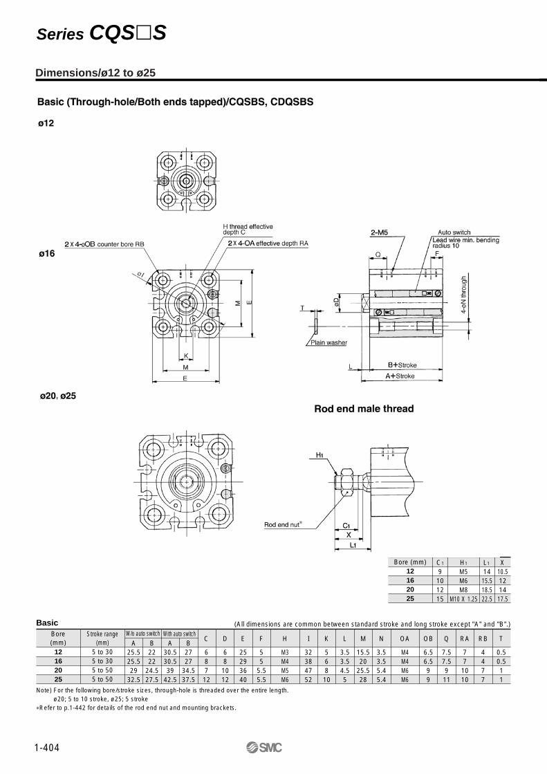
Dimensions/ø12 to ø25
Rod end male threadBore (mm)
12162025
C1
9101215
H1
M5M6M8
M10 X 1.25
L1
1415.518.522.5
X10.5121417.5
BasicBore(mm)
Stroke range(mm) A
25.525.529
32.5
B2222
24.527.5
A30.530.539
42.5
B2727
34.537.5
C
687
12
D
68
1012
E
25293640
F
55
5.55.5
H
M3M4M5M6
I
32384752
K
56810
L
3.53.54.55
M
15.520
25.528
N
3.53.55.45.4
OA
M4M4M6M6
OB
6.56.599
Q
7.57.5911
RA
771010
RB
4477
T
0.50.511
12162025
5 to 305 to 305 to 505 to 50
W/o auto switch With auto switch(All dimensions are common between standard stroke and long stroke except "A" and "B".)
Note) For the following bore/stroke sizes, through-hole is threaded over the entire length.ø20; 5 to 10 stroke, ø25; 5 stroke
∗Refer to p.1-442 for details of the rod end nut and mounting brackets.
1-404
Series CQS�S

Bore(mm)
Stroke range(mm)
Bore(mm)
Stroke range(mm)
Bore(mm)
Without auto switch With auto switch
Without auto switch With auto switch
12162025
12162025
12162025
5 to 305 to 305 to 505 to 50
40.340.346.249.7
13.513.514.515
5 to 305 to 305 to 505 to 50
L L1 LD LG LH LT LX LY LZ X Y
2425.528.532.5
4.54.56.66.6
2.82.844
17192426
22
3.23.2
34384852
29.533.54246
44486266
88
9.210.7
4.55
5.85.8
A
35.535.539
42.5
A2222
24.527.5
B40.540.549
52.5
A2727
34.537.5
B
B LS A B LS2222
24.527.5
1010
12.512.5
45.345.356.259.7
2727
34.537.5
1515
22.522.5
Foot
Front flange
Bore(mm)
12162025
4.54.56.66.6
FD
5.55.588
FT
25303942
FV
45454852
FX
55556064
FZ
13.513.514.515
L
2425.528.532.5
L1
Bore(mm)
Stroke range(mm)
Without auto switch With auto switch
12162025
5 to 305 to 305 to 505 to 50
313137
40.5
A2222
24.527.5
B363647
50.5
A2727
34.537.5
B
Rear flange
Bore(mm)
12162025
4.54.56.66.6
FD
5.55.588
FT
25303942
FV
45454852
FX
55556064
FZ
3.53.54.55
L
1415.518.522.5
L1
Bore(mm)
Stroke range(mm)
Without auto switch With auto switch
12162025
5 to 305 to 305 to 505 to 50
45.546.556
62.5
A2222
24.527.5
B39.540.547
52.5
CL50.551.566
72.5
A2727
34.537.5
B44.545.557
62.5
CL
Double clevis
Bore(mm)
12162025
55810
CD
4455
CT
7101214
CU
14151820
CW
56.5810
CX
10121620
CZ
3.53.54.55
L
1415.518.522.5
L1
669
10
RR
∗Refer to p.1-442 detail of the rod end nut and mounting brackets.
(All dimensions are common between standardstroke and long stroke except "A", "B" and "LS".)
(All dimensions are common between standardstroke and long stroke except "A" and "B". )
(All dimensions are common between standardstroke and long stroke except "A" and "B".)
(All dimensions are common between standardatroke and long stroke except "A", "B" and "CL".)
1-405
Compact Cylinder/Anti-lateral Load Series CQS�S

1-406

ø12, ø16ø20, ø25
Applicable auto switchApplicable bore size Auto switch model Electrical entry
Reed switch
Solid state switch
D-A90
D-A93
D-A96
D-A90V
D-A93V
D-A96V
D-M9N
D-M9P
D-M9B
D-M9NW
D-M9PW
D-M9BW
D-M9NV
D-M9PV
D-M9BV
D-M9NWV
D-M9PWV
D-M9BWV
D-M9BAL
Grommet
• If the cylinder is used in an application in which a magnetic material is placed in close contact aroundthe cylinder as shown in the diagram on the right (including cases in which even one of the sides is in close contact) the operation of auto switches could become unstable. Therefore, check with SMC for this type of application.
2 wire, In-line
3 wire, In-line
2 wire, Perpendicular
3 wire, Perpendicular
3 wire, NPN, In-line
3 wire, PNP, In-line
2 wire, In-line
3 wire, NPN, In-line (2 colour)
3 wire, PNP, In-line (2 colour)
2 wire, In-line(2 colour)
3 wire, NPN, Perpendicular
3 wire, Water resistant
2 wire, Perpendicular
3 wire, NPN, Perpendicular(2 colour)
3 wire, Water resistant(2 colour)
2 wire, Perpendicular(2 colour)
2 wire, In-line(2 colour), Water resistant
Precautions
1-407
Series CQSAuto Switch SpecificationsRefer to p.6-15 of details of auto switch.

D-M9�
D-M9�VD-M9�WV
D-M9�WD-M9BAL
Auto Switch Mounting Position and Mounting Height(Double acting single rod, Single acting single rod/spring return, spring extend, Long stroke, Anti-lateral load, Double acting double rod)
Mounting
a) b) a) b)
Mountingø16 to ø25ø12
Series CQS

Auto switch model No. D-A9� D-A9�VD-M9N/D-M9B
D-M9P/D-M9�W D-M9�V/D-M9�WV
Symbol A B W A B W A B WA B HS
Bore size(mm)
Bore size(mm)
Bore size(mm)
Bore size(mm)
Bore size(mm)
Bore size(mm)
Bore size(mm)
Bore size(mm)
Double acting: single rod, Single acting: single rod/spring return, spring extend
Long stroke
Anti-lateral load
Double acting: double rod
Double acting: single rod, Single acting: single rod/spring return, spring extend
Long stroke
Anti-lateral load
Double acting: double rod
12
162025
12162025
12162025
55.5910
65.5910
12162025
12
16
20
25
4.5
5
9
10
3.5
3
6.5
8.5
14.5
15
11.5
9.5
16.5
18.5
22
24
12
16
20
25
8
8.5
12
13
10
9.5
15
17
16.5
18.5
22
24
8
8.5
3
1
12
16
20
25
9
8.5
12
13
4
4.5
8.5
10.5
14
13.5
9.5
7.5
16.5
18.5
22
24
12
16
20
25
4.5
5
9
10
8.5
8
13
15
9.5
10
5
3
16.5
18.5
22
24
1.5267
5.55
1012
3.5[6]3[5.5]
8[10.5]10[12.5]
1.5267
5.55
1012
1719
22.524.5
5.561011
9.591416
0.51
–4–6
5.561011
9.591416
19.521.52527
0.5157
1[3.5]0.5[3]
–3.5[-1]–5.5[-3]
65.59
10
0.5157
1719
22.524.5
109.51314
55.59.511.5
54.50.5–1.5
109.51314
55.59.511.5
19.521.52527
76
11.513.5
–5[-2.5]–4.5[-2]–10[-7.5]–12[-9.5]
55.59
10
76
11.513.5
99.51314
1110.51618
99.51314
1110.51618
19.521.52527
–1–0.5–6–8
1719
22.524.5
1.5(2.5)
267
0
03.55.5
1.5[4](2.5[5])2[4.5]
–1.5[1]–3.5[-1]
1.5(2.5)
267
0
03.55.5
17
1922.524.5
5.5
61011
4.5
47.59.5
5.5
62.50.5
5.5(6.5)
61011
4.5(3.5)
47.59.5
19
2124.526.5
Auto switch model No. D-M9BAL
Symbol A B W HS
Note 1) The product is shipped out of the factory in installation state "a)". To change the electrical entry direction of the switch on the head, refer to installation state "b)".
Note 2) In the W column in the table, if the indicated dimensionis a negative number, the auto switch must be installed inward from the end of the cylinder body.
Note 3) The D-M9N, M9B, M9P, M9�W, and M9BAL cannot beinstalled on the single acting: single rod style.
1-409
Auto Switch Mounting Position and Mounting Height Series CQS

D-M9�D-M9�W
D-M9�VD-M9�WV
D-M9BAL
1-410
Series CQS
Auto Switch Mounting Position and Mounting Height (Non-rotating rod)
D-A9� D-M9�V/D-M9�WVD-A9�V D-M9N/D-M9BD-M9P/D-M9�W
Auto switchmodel
Symbol
Bore size(mm)
12
16
20
25
1.5
2
6
7
A
D-M9BALAuto switchmodel
Symbol
Bore size(mm)
12
16
20
25
4.5
5
9
10
A
0
0
3.5
5.5
B1.5(4)
2(4.5)
–1.5(1)
–3.5(-1)
W1.5
2
6
7
A0
0
3.5
5.5
B17
19
22.5
24.5
Hs5.5
6
10
11
A
3.5
3
6.5
8.5
B14.5
15
11.5
9.5
W16.5
18.5
22
24
Hs
4.5
4
7.5
9.5
B5.5
6
2.5
0.5
W5.5
6
10
11
A4.5
4
7.5
9.5
B19
21
24.5
26.5
W
Note 1) The product is shipped out of the factory in installation state "a)". To change the electrical entry direction of theswitch on the head, refer to installation state "b)".