communication technology equipment kowloon, hong … · 16th fl, lu plaza, 2 wing yip st, kwun...
TRANSCRIPT
File E132002
Project 4788088723
September 07, 2017
REPORT
on
COMPONENT - POWER SUPPLIES FOR USE WITH AUDIO/VIDEO, INFORMATION AND
COMMUNICATION TECHNOLOGY EQUIPMENT
Astec International Ltd
KOWLOON, HONG KONG
Copyright 2017 UL LLC
UL LLC authorizes the above named company to reproduce this Report only for
purposes as described in the Conclusion. The Report should be reproduced in
its entirety; however to protect confidential product information, the
Construction Details Descriptive pages may be excluded.
File E132002 Vol. 27 Sec. 2 Page 1 Issued: 2017-09-07
and Report
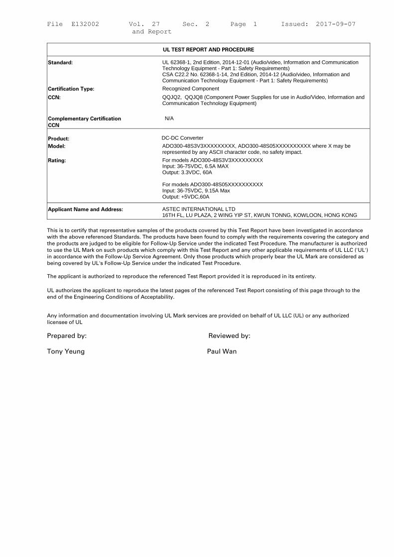
UL TEST REPORT AND PROCEDURE
Standard: UL 62368-1, 2nd Edition, 2014-12-01 (Audio/video, Information and Communication Technology Equipment - Part 1: Safety Requirements) CSA C22.2 No. 62368-1-14, 2nd Edition, 2014-12 (Audio/video, Information and Communication Technology Equipment - Part 1: Safety Requirements)
Certification Type: Recognized Component
CCN: QQJQ2, QQJQ8 (Component Power Supplies for use in Audio/Video, Information and Communication Technology Equipment)
Complementary Certification
CCN
N/A
Product:
DC-DC Converter
Model: ADO300-48S3V3XXXXXXXXX, ADO300-48S05XXXXXXXXXX where X may be represented by any ASCII character code, no safety impact.
Rating: For models ADO300-48S3V3XXXXXXXXX Input: 36-75VDC, 6.5A MAX Output: 3.3VDC, 60A For models ADO300-48S05XXXXXXXXXX Input: 36-75VDC, 9.15A Max Output: +5VDC,60A
Applicant Name and Address: ASTEC INTERNATIONAL LTD 16TH FL, LU PLAZA, 2 WING YIP ST, KWUN TONNG, KOWLOON, HONG KONG
This is to certify that representative samples of the products covered by this Test Report have been investigated in accordance
with the above referenced Standards. The products have been found to comply with the requirements covering the category and
the products are judged to be eligible for Follow-Up Service under the indicated Test Procedure. The manufacturer is authorized
to use the UL Mark on such products which comply with this Test Report and any other applicable requirements of UL LLC ('UL')
in accordance with the Follow-Up Service Agreement. Only those products which properly bear the UL Mark are considered as
being covered by UL's Follow-Up Service under the indicated Test Procedure.
The applicant is authorized to reproduce the referenced Test Report provided it is reproduced in its entirety.
UL authorizes the applicant to reproduce the latest pages of the referenced Test Report consisting of this page through to the
end of the Engineering Conditions of Acceptability.
Any information and documentation involving UL Mark services are provided on behalf of UL LLC (UL) or any authorized
licensee of UL
Prepared by: Reviewed by:
Tony Yeung Paul Wan
File E132002 Vol. 27 Sec. 2 Page 2 Issued: 2017-09-07
and Report
Supporting Documentation
The following documents located at the beginning of this Procedure supplement the requirements of this Test
Report:
A. Authorization - The Authorization page may include additional Factory Identification Code markings.
B. Generic Inspection Instructions -
i. Part AC details important information which may be applicable to products covered by this Procedure.
Products described in this Test Report must comply with any applicable items listed unless otherwise
stated in the body of this Test Report
ii. Part AE details any requirements which may be applicable to all products covered by this Procedure.
Products described in this Test Report must comply with any applicable items listed unless otherwise
stated in the body of each Test Report
C. Listing Mark/Recognized Component Mark Data Page - details the requirements for the
UL Certification Mark which is not controlled by the technical standard used to investigate these products.
Products are permitted to bear only the Certification Mark(s) corresponding to the countries for which it is
certified, as indicated in each Test Report.
Product Description
The equipment is DC-DC Converter, intended for building in as a component used in Audio, Video and
information technology equipment. Basic insulation is provided between the input circuit and base plate /
output circuit.
Model Differences
N/A
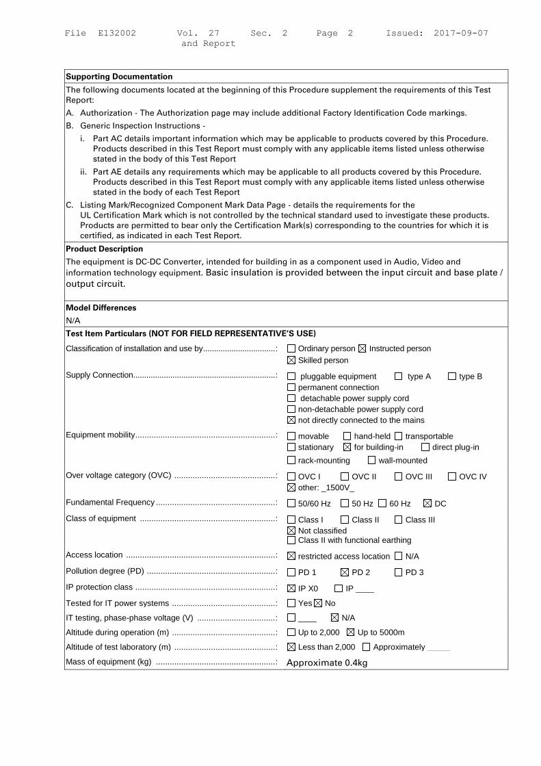
Test Item Particulars (NOT FOR FIELD REPRESENTATIVE’S USE)
Classification of installation and use by ................................. : Ordinary person Instructed person
Skilled person
Supply Connection ................................................................. : pluggable equipment type A type B
permanent connection
detachable power supply cord
non-detachable power supply cord
not directly connected to the mains
Equipment mobility ............................................................. : movable hand-held transportable
stationary for building-in direct plug-in
rack-mounting wall-mounted
Over voltage category (OVC) ............................................ : OVC I OVC II OVC III OVC IV
other: _1500V_
Fundamental Frequency .................................................... : 50/60 Hz 50 Hz 60 Hz DC
Class of equipment ........................................................... : Class I Class II Class III
Not classified Class II with functional earthing
Access location ................................................................. : restricted access location N/A
Pollution degree (PD) ........................................................ : PD 1 PD 2 PD 3
IP protection class ............................................................. : IP X0 IP ____
Tested for IT power systems ............................................. : Yes No
IT testing, phase-phase voltage (V) .................................. : ____ N/A
Altitude during operation (m) ............................................. : Up to 2,000 Up to 5000m
Altitude of test laboratory (m) ............................................ : Less than 2,000 Approximately _____
Mass of equipment (kg) .................................................... : Approximate 0.4kg
File E132002 Vol. 27 Sec. 2 Page 3 Issued: 2017-09-07
and Report
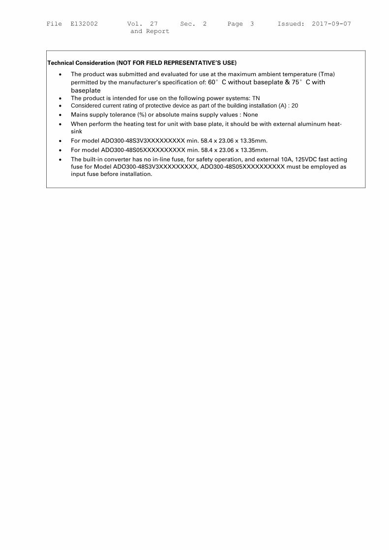
Technical Consideration (NOT FOR FIELD REPRESENTATIVE’S USE)
• The product was submitted and evaluated for use at the maximum ambient temperature (Tma)
permitted by the manufacturer’s specification of: 60°C without baseplate & 75°C with
baseplate
• The product is intended for use on the following power systems: TN
• Considered current rating of protective device as part of the building installation (A) : 20
• Mains supply tolerance (%) or absolute mains supply values : None
• When perform the heating test for unit with base plate, it should be with external aluminum heat-
sink
• For model ADO300-48S3V3XXXXXXXXX min. 58.4 x 23.06 x 13.35mm.
• For model ADO300-48S05XXXXXXXXXX min. 58.4 x 23.06 x 13.35mm.
• The built-in converter has no in-line fuse, for safety operation, and external 10A, 125VDC fast acting
fuse for Model ADO300-48S3V3XXXXXXXXX, ADO300-48S05XXXXXXXXXX must be employed as
input fuse before installation.

File E132002 Vol. 27 Sec. 2 Page 4 Issued: 2017-09-07
and Report
Engineering Conditions of Acceptability (NOT FOR FIELD REPRESENTATIVE’S USE)
For use only in or with complete equipment where the acceptability of the combination is determined by UL LLC.
When installed in an end-product, consideration must be given to the following:
• The following Production-Line tests are conducted for this product: Electric Strength
• The end-product Electric Strength Test is to be based upon a maximum working voltage of: Primary-
SELV: 42.16 Vrms, 115.0 Vpk, DC input-DC output: _75__ Vrms, _75__ Vpk,
• The following output circuits are at ES1 energy levels: Output circuit
• The following output circuits are at PS3 energy levels: Output circuit
• The maximum investigated branch circuit rating is: 20 A
• The investigated Pollution Degree is: 2
• Proper bonding to the end-product main protective earthing termination is: Required
• An investigation of the protective bonding terminals has: Been conducted
• The following end-product enclosures are required: Mechanical, Fire, Electrical
• The following magnetic devices (e.g. transformers or inductor) are provided with an OBJY2
insulation system with the indicated rating greater than Class A (105°C): T2 (class F)
• External forced Air Cooling employed with minimum 800LFM airflow, the airflow direction
is from Vin- to Vin+.
• The power supply was evaluated to be used at altitudes up to: 5,000 m
Additional Information
N/A
Additional Standard
The product fulfils the requirements of:
N/A
File E132002 Vol. 27 Sec. 2 Page 5 Issued: 2017-09-07
and Report
Markings, instructions and instructional safeguards
Clause Title Marking or Instruction Details
English French
62368-1
Equipment identification marking – Manufacturer identification
Listee's or Recognized company's name, Trade Name, Trademark or File Number
Equipment identification marking – model identification
Model Number
Equipment rating marking –ratings
Input Ratings (voltage, frequency/dc, current/power) Output Ratings (voltage, frequency/dc, current/power)
Special Instructions to UL Representative
For transformer test - When the tests are conducted at other location, inspect test record and specification sheet provided by the component manufacturer. Verify the specification sheet indicates 100% routine test specified in Production-Line Testing Requirements be conducted at the component manufacturer.
Production-Line Testing Requirements
Electric Strength Test Special Constructions - Refer to Generic Inspection Instructions, Part AC for
further information.
Model Component
Removable
Parts Test probe location V rms V dc
Test
Time, s
N/A
Earthing Continuity Test Exemptions - This test is not required for the following models:
--
Electric Strength Test Exemptions - This test is not required for the following models:
--
Electric Strength Test Component Exemptions - The following solid-state components may be
disconnected from the remainder of the circuitry during the performance of this test:
--
Sample and Test Specifics for Follow-Up Tests at UL
Model Component Material Test Sample(s)
Test
Specifics
N/A

File E132002 Vol. 27 Sec. 2 Page 6 Issued: 2017-09-07
and Report
4.1.2 TABLE: list of critical components Pass
Object/part or Description Manufacturer/
trademark
type/model technical data Product Category
CCN(s)
Required
Marks of
Conformity
Supplement ID
For model ADO300-48S3V3XXXXXXXXX
-- -- -- -- --
PCB Interchangeable Interchangeable Rated V-0, Min. 130 degree C ZPMV2 UL
Transformer Core
(CoreT3)
Interchangeable Embeded in PCB Min.130 degree C -- Tested in
product
Transformer (T2) Artesyn / Astec 801-007221-
XXXX
Provided with Class F
Insulation system under
E94225, OBJY2, designed
155-10C
XORU3 (E127000)
UL
Transformer (T2) -
Alternate
Day One 800-003125-
XXXX
Provided with Class F
Insulation system under
E94225, OBJY2, designed
155-10C
XORU3 (E127000)
UL
High Voltage Capacitor
(C64)
Johanson X7R Series Min. 1500 Vdc -- Tested in
product
High Voltage Capacitor
(C64) - Alternate
HOLY STONE X7R Series Min. 1500 Vdc -- Tested in
product
Base Plate (Optional) Interchangeable Interchangeable Overall dimension Min. 58.4
x 23.06 x 13.35mm
-- Tested in
product
Opto-coupler (U2) Texas (E181974) ISO7141 series Min. 1500 Vdc FPQU2/8 UL
Opto-coupler (U2) -
Alternate
Silicon (E257455) Si8641 series Min. 1500 Vdc FPQU2/8 UL
For model ADO300-
48S05XXXXXXXXX
-- -- -- -- --
PCB Interchangeable Interchangeable Rated V-0, Min. 130 degree C UL 796, IEC
62368-1
UL, Tested
in product.
Transformer Core
(CoreT2)
Interchangeable Embeded in PCB Min.130 degree C IEC62368-1 --, Tested in
product.
Transformer (T2) Artesyn / Astec 801-007221-
XXXX
Provided with Class F
Insulation system under
E94225, OBJY2, designed
155-10C
IEC62368-1 --, Tested in
product.
Transformer (T2) - Day One 800-003125- Provided with Class F IEC62368-1 --, Tested in
File E132002 Vol. 27 Sec. 2 Page 7 Issued: 2017-09-07
and Report
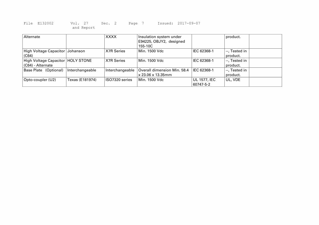
Alternate XXXX Insulation system under
E94225, OBJY2, designed
155-10C
product.
High Voltage Capacitor
(C64)
Johanson X7R Series Min. 1500 Vdc IEC 62368-1 --, Tested in
product.
High Voltage Capacitor
(C64) - Alternate
HOLY STONE X7R Series Min. 1500 Vdc IEC 62368-1 --, Tested in
product.
Base Plate (Optional) Interchangeable Interchangeable Overall dimension Min. 58.4
x 23.06 x 13.35mm
IEC 62368-1 --, Tested in
product.
Opto-coupler (U2) Texas (E181974) ISO7320 series Min. 1500 Vdc UL 1577, IEC
60747-5-2
UL, VDE

File E132002 Vol. 27 Sec. 2 Page 8 Issued: 2017-09-07
and Report
ENCLOSURES
Type Supplement Id Description
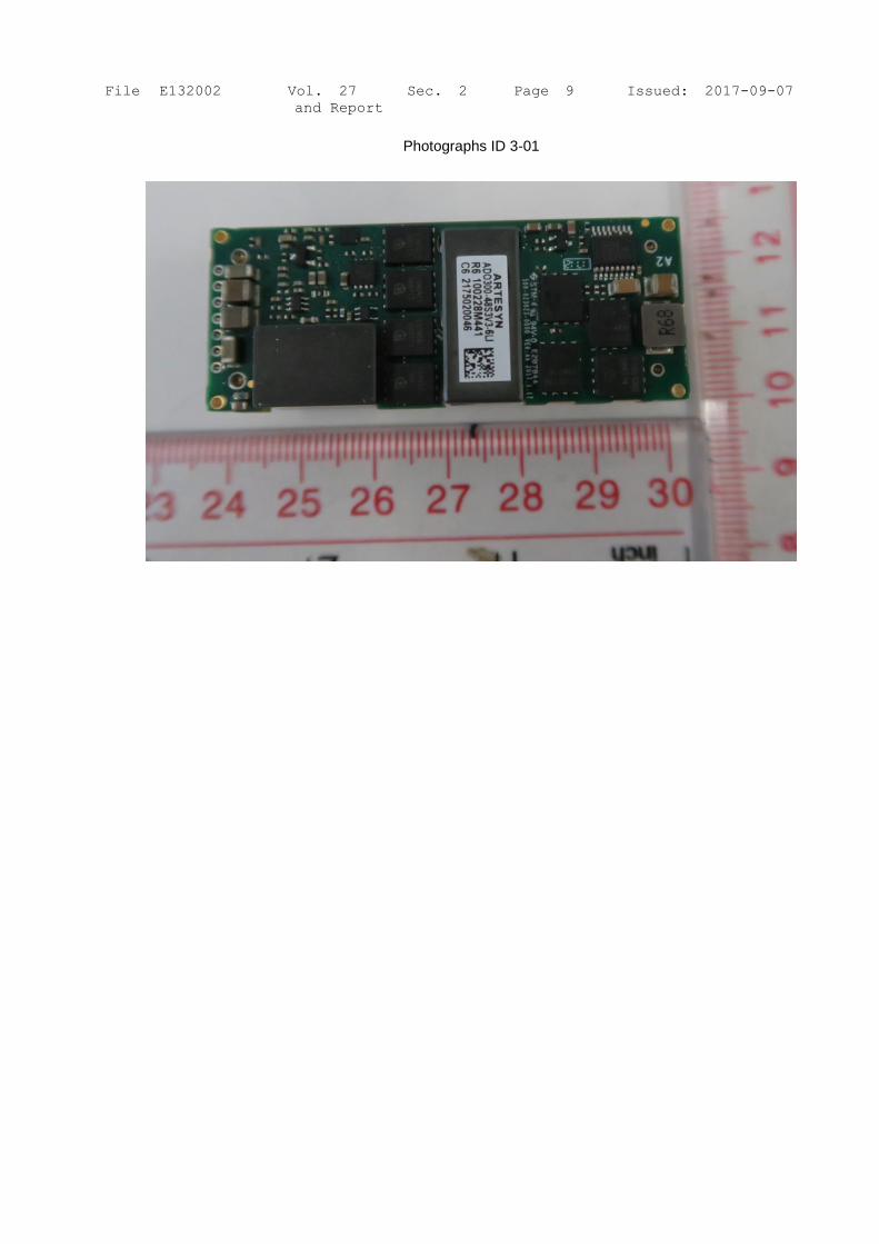
Photographs 3-01 Outlook View 1, for model
ADO300-48S3V3XXXXXXXXX
Photographs 3-02 Outlook View 2, for model
ADO300-48S3V3XXXXXXXXX
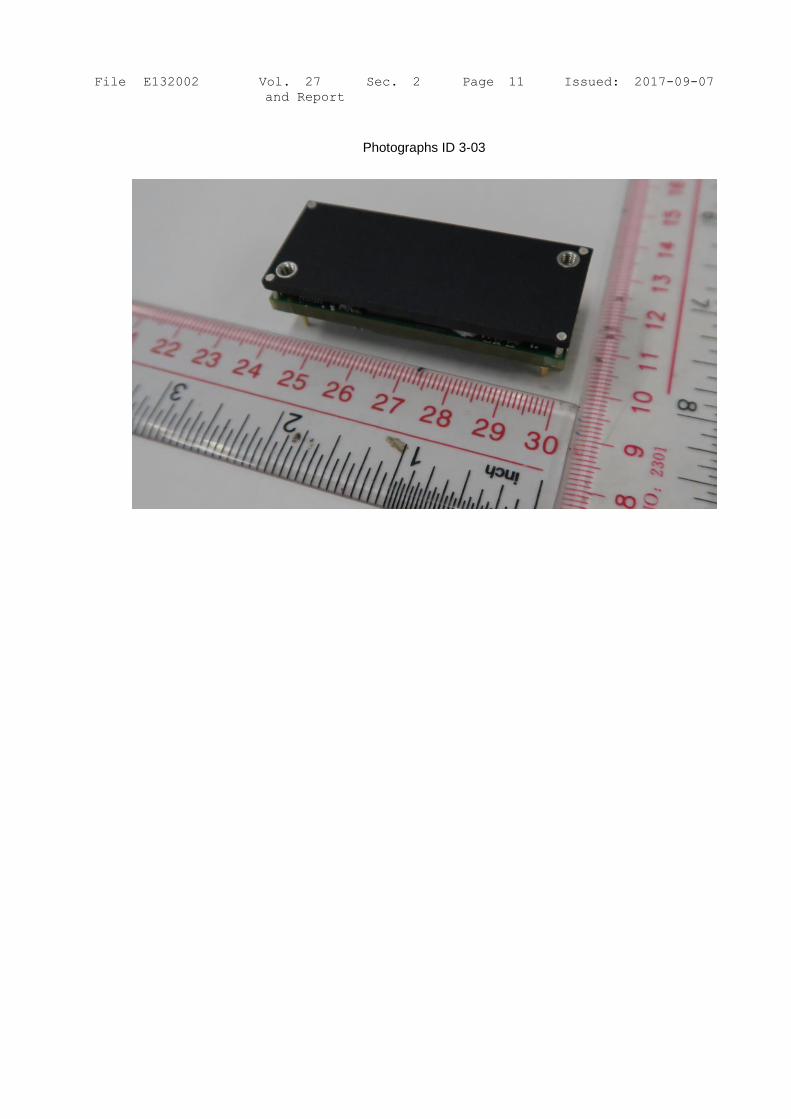
Photographs 3-03 Outlook View 3, for model
ADO300-48S3V3XXXXXXXXX
Photographs 3-04 Outlook View 1, for model
ADO300-48S05XXXXXXXXXX
Photographs 3-05 Outlook View 2, for model
ADO300-48S05XXXXXXXXXX
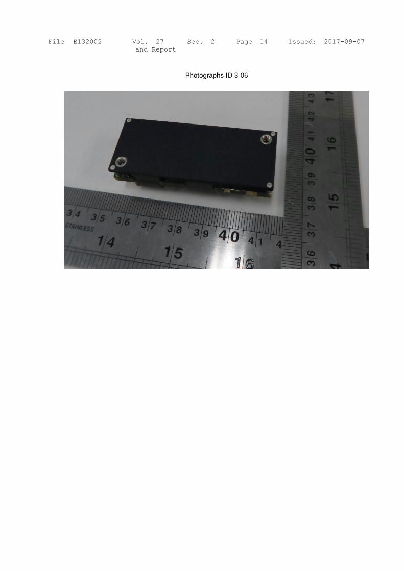
Photographs 3-06 Outlook View 3, for model
ADO300-48S05XXXXXXXXXX
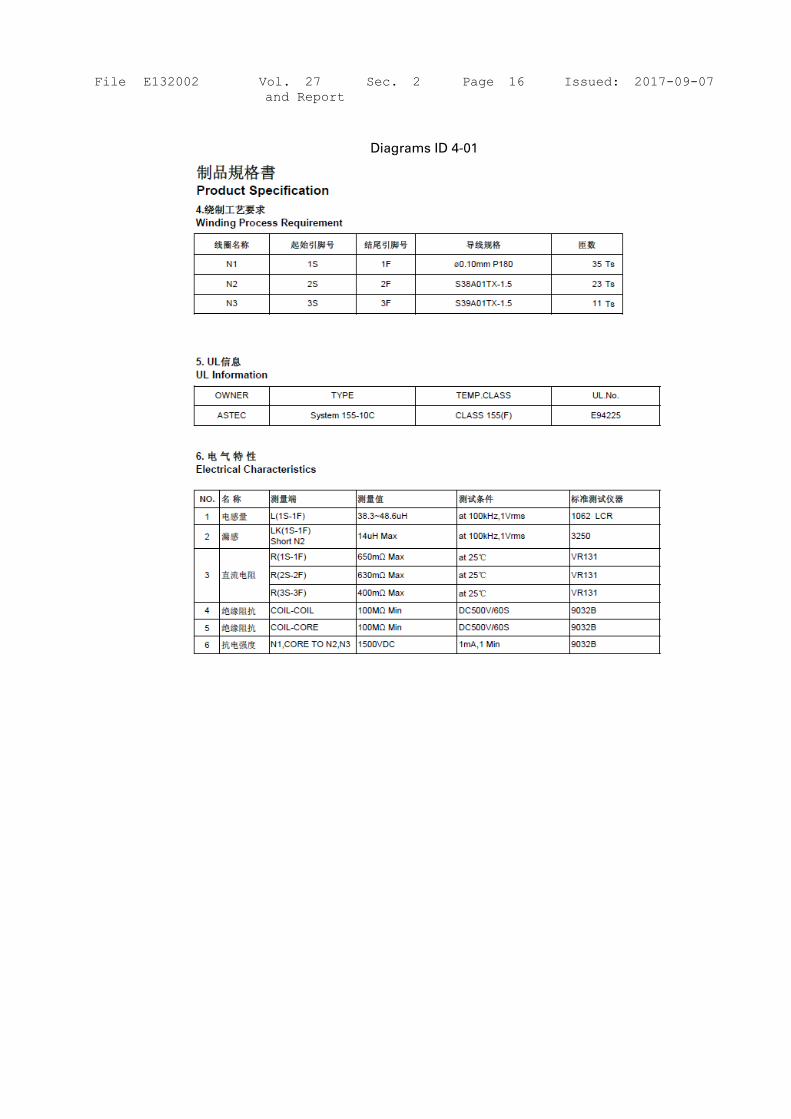
Diagrams 4-01 Specification of transformer (T2)
Schematics + PWB 5-01 PCB Layout (Component side & solder side) for model
ADO300-48S3V3XXXXXXXXX
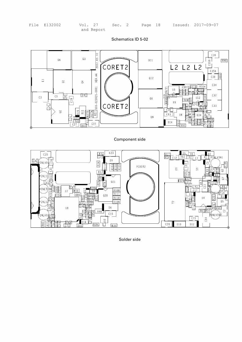
Schematics + PWB 5-02 PCB Layout (Component side & solder side) for model
ADO300-48S05XXXXXXXXX
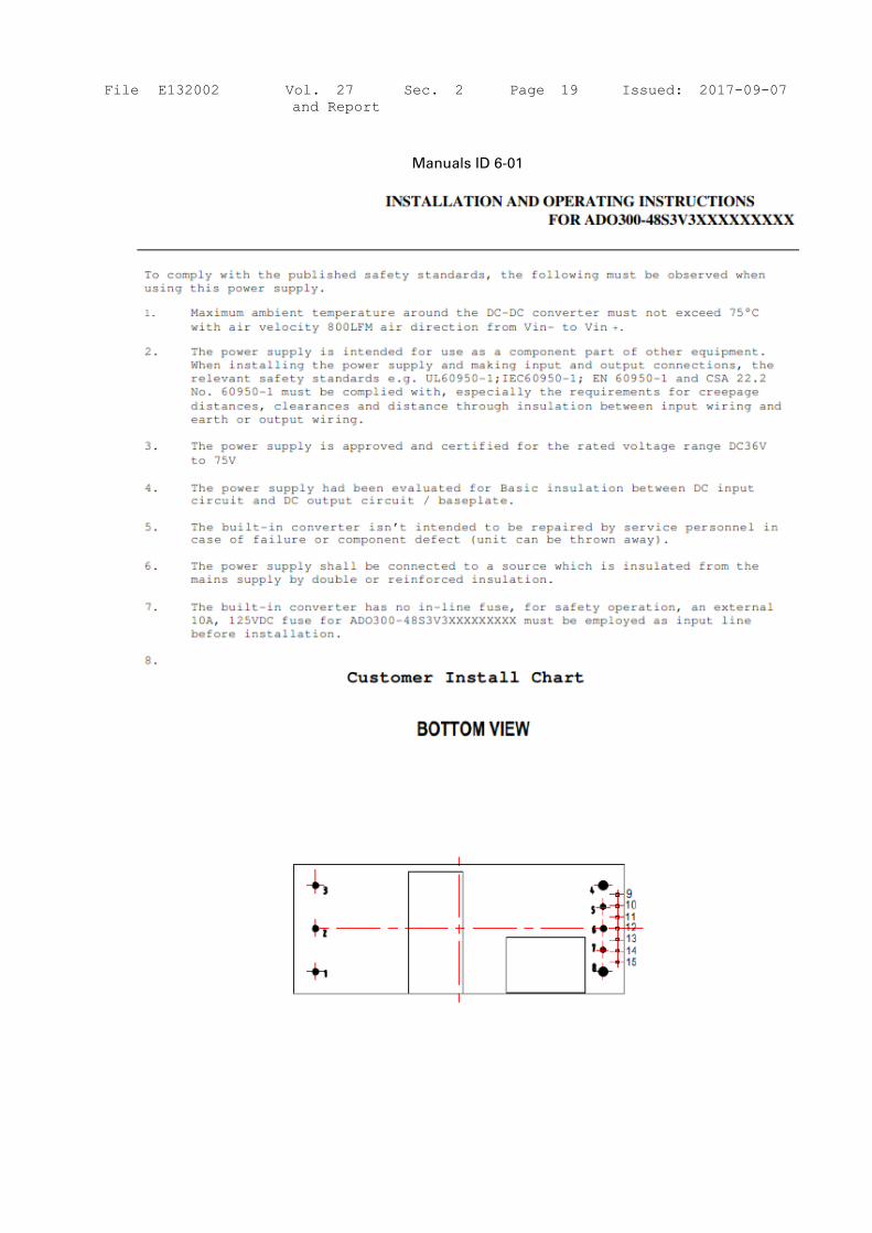
Manuals 6-01 Installation and Operation Instructions for model ADO300-
48S3V3XXXXXXXXX
Manuals 6-02 Installation and Operation Instructions for model ADO300-
48S05XXXXXXXXX
File E132002 Vol. 27 Sec. 2 Page 9 Issued: 2017-09-07
and Report
Photographs ID 3-01

File E132002 Vol. 27 Sec. 2 Page 10 Issued: 2017-09-07
and Report
Photographs ID 3-02
File E132002 Vol. 27 Sec. 2 Page 11 Issued: 2017-09-07
and Report
Photographs ID 3-03

File E132002 Vol. 27 Sec. 2 Page 12 Issued: 2017-09-07
and Report
Photographs ID 3-04

File E132002 Vol. 27 Sec. 2 Page 13 Issued: 2017-09-07
and Report
Photographs ID 3-05
File E132002 Vol. 27 Sec. 2 Page 14 Issued: 2017-09-07
and Report
Photographs ID 3-06

File E132002 Vol. 27 Sec. 2 Page 15 Issued: 2017-09-07
and Report
Diagrams ID 4-01
File E132002 Vol. 27 Sec. 2 Page 16 Issued: 2017-09-07
and Report
Diagrams ID 4-01

File E132002 Vol. 27 Sec. 2 Page 17 Issued: 2017-09-07
and Report
Schematics ID 5-01
Component side
Solder side
File E132002 Vol. 27 Sec. 2 Page 18 Issued: 2017-09-07
and Report
Schematics ID 5-02
Component side
Solder side
File E132002 Vol. 27 Sec. 2 Page 19 Issued: 2017-09-07
and Report
Manuals ID 6-01

File E132002 Vol. 27 Sec. 2 Page 20 Issued: 2017-09-07
and Report
Manuals ID 6-01
Manuals ID 6-02
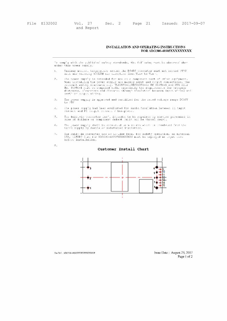
File E132002 Vol. 27 Sec. 2 Page 21 Issued: 2017-09-07
and Report

File E132002 Vol. 27 Sec. 2 Page 22 Issued: 2017-09-07
and Report
Manuals ID 6-02