communicating and controlling robot - brown university
TRANSCRIPT
ISRR 2017
The International Journal of
Robotics Research
1–13
� The Author(s) 2019
Article reuse guidelines:
sagepub.com/journals-permissions
DOI: 10.1177/0278364919842925
journals.sagepub.com/home/ijr
Communicating and controlling robotarm motion intent through mixed-realityhead-mounted displays
Eric Rosen*, David Whitney*, Elizabeth Phillips, Gary Chien,
James Tompkin, George Konidaris and Stefanie Tellex
Abstract
Efficient motion intent communication is necessary for safe and collaborative work environments with co-located humans
and robots. Humans efficiently communicate their motion intent to other humans through gestures, gaze, and other non-
verbal cues, and can replan their motions in response. However, robots often have difficulty using these methods. Many
existing methods for robot motion intent communication rely on 2D displays, which require the human to continually
pause their work to check a visualization. We propose a mixed-reality head-mounted display (HMD) visualization of the
intended robot motion over the wearer’s real-world view of the robot and its environment. In addition, our interface allows
users to adjust the intended goal pose of the end effector using hand gestures. We describe its implementation, which con-
nects a ROS-enabled robot to the HoloLens using ROS Reality, using MoveIt for motion planning, and using Unity to ren-
der the visualization. To evaluate the effectiveness of this system against a 2D display visualization and against no
visualization, we asked 32 participants to label various arm trajectories as either colliding or non-colliding with blocks
arranged on a table. We found a 15% increase in accuracy with a 38% decrease in the time it took to complete the task
compared with the next best system. These results demonstrate that a mixed-reality HMD allows a human to determine
where the robot is going to move more quickly and accurately than existing baselines.
Keywords
Mixed reality, motion planning, human–robot interaction
1. Introduction
Industrial robots excel at performing precise, accurate,
strenuous, and repetitive tasks, which makes them ideal for
activities such as car assembly. A major drawback of these
robots is that humans are unable to easily predict their
motions, which forces most industrial robots to be isolated
from human workers and restricts human–robot collabora-
tion. This is especially true in a fluid working environment
without rigidly defined tasks, or where robots move auton-
omously. Although the intended robot motion is defined
ahead of time through motion planning, efficiently convey-
ing the intended motion to a human is difficult. Human–
robot collaboration requires robots to communicate to
humans in ways that are intuitive and efficient (Fong et al.,
2003); yet, the motion intention inference problem leads to
many safety and efficiency issues for humans working
around robots (Han, 2016).
This problem has inspired research into how robots
might effectively communicate intent to humans. Current
interfaces for communicating robot intent have limitations
in expressing motion plans within a shared workspace.
Humanoid robots can try to mimic the gestures and social
cues that humans use with each other, but many robots are
not and cannot be humanoid by design. The motion robots
intend to make can also be visualized on a 2D display near
the robot. This requires the human to take their attention
away from the robot’s physical space to observe the display,
which could be dangerous. In addition, a 2D projection of
a 3D motion plan can take time for a human to understand,
requiring interaction to inspect different points of view.
Humans To Robots Laboratory, Department of Computer Science,
Providence, RI, USA
*The first two authors contributed equally and are listed alphabetically.
Corresponding author:
Eric Rosen, Humans To Robots Laboratory, Department of Computer
Science, 115 Waterman Street, Providence, RI 02912, USA.
Email: [email protected]
Natural communication might be achieved when
humans can see a robot’s future motion in the real world
from their own point of view, via a head-mounted display
(HMD) (Ruffaldi et al., 2016; Scassellati and Hayes,
2014). This could increase safety and efficiency as the
human no longer needs to divert their attention. Further, as
the 3D motion plan would be overlaid in 3D space, human
users would not need to make sense of 2D projections of
3D objects.
We test this idea with a system that enables humans to
view robot intended motion via 3D graphics on a mixed-
reality (MR) HMD: the Microsoft HoloLens. This allows a
participant to visualize the robot arm motion in the real
workspace before it moves, preventing collisions with the
human or with objects (Figure 1). As there is no existing
open-source HoloLens ROS integration for the robotics
community, we have released our code: https://github.com/
h2r/Holobot. This integrates HoloLens with the widely used
Unity game engine, provides a Unified Robot Description
Format (URDF) parser to quickly import robots into Unity,
and network code to send messages between the robot and
HoloLens.
In addition to visualizing robot motion intent, it is
important for the robot to be able to replan an intended tra-
jectory based on human response, i.e., when the user
notices that the planned robot trajectory will collide with
objects in the environment. Using MoveIt (Chitta et al.,
2012), we allow a user to command the robot to plan new
trajectories with the same start and end points, and so visua-
lize and choose from different robot motion trajectories.
We experimentally compare our system with both a 2D
display interface and a control condition with no visualiza-
tion (Figure 4). In a within-subjects-design study, 32 parti-
cipants used all three system variants to classify arm
motion plans of a Rethink Robotics Baxter as either collid-
ing or not colliding with blocks on a table. Our MR system
reduced task completion time by 7.4 seconds on average (a
reduction of 38%), increased precision by 11% on average,
and increased accuracy by 15% on average, compared with
the next best system (2D display). In addition, we improved
subjective assessments of system usability (System
Usability Scale (SUS)) (Brooke et al., 1996) and mental
workload (NASA Task Load Index) (NASA Human
Performance Research Group and others, 1987). This
experiment shows the promise of MR-HMDs to further
human–robot collaboration.
2. Related work
Humans use many non-verbal cues to communicate motion
intent. There is much work in approximating these cues in
humanoid robots, focusing especially on gestures (Nakata
et al., 1998) and gaze (Mutlu et al., 2009), as well as related
work on non-verbal communication with non-humanoid
robots (Cha et al., 2018). However, robots often lack the
faculty or subtlety to physically reproduce human non-
verbal cues, especially robots that are not of humanoid
form. One alternative is to use animation and animated
storytelling techniques, such as forming suggestive poses
or generating initial movements (Takayama et al., 2011).
This increases legibility: the ability to infer the robot’s goal
through its directed motion (Dragan et al., 2013). However,
these methods still lack the ability to transparently commu-
nicate complex paths and motions. Further, tasks involving
close proximity teamwork may require more detailed
knowledge of how the robot will act both before and during
the motion, such as in collaborative furniture assembly
(Scassellati and Hayes, 2014) and co-located teleoperation
(Szafir et al., 2014).
Verbal communication has also been shown to be an
effective way to have robots communicate their high-level
intent Nikolaidis et al. (2017). However, although speech is
useful for quickly expressing abstract actions such as ‘‘I will
rotate the table,’’ it is difficult to communicate low-level
actions such as what joint angles the robot will assume
throughout the planned motion. Not only is it cumbersome
for the robot to explicitly state all of the relevant informa-
tion for describing a high-degree-of-freedom (high-DoF)
arm motion, it is not expected for humans to be able to eas-
ily interpret such speech because humans do not typically
talk in this manner.
Other related works have used turn and display indica-
tors on the robot to communicate navigational intent
(Chadalavada et al., 2016; Schaefer et al., 2017; Szafir
et al., 2015). These techniques were found to improve
human trust and confidence in robot actions; however, they
did not express high detail in the motion plan (Shrestha
et al., 2016a,b).
We can also use 2D displays to visualize the robot’s
future motions within its environment through systems
such as RViz (Kam et al., 2015; Leeper et al., 2012). These
require the human operator to switch focus from the real-
world environment to the visualization display (Milgram
et al., 1993). This may lead the operator to expend more
time understanding the robot state and environment rather
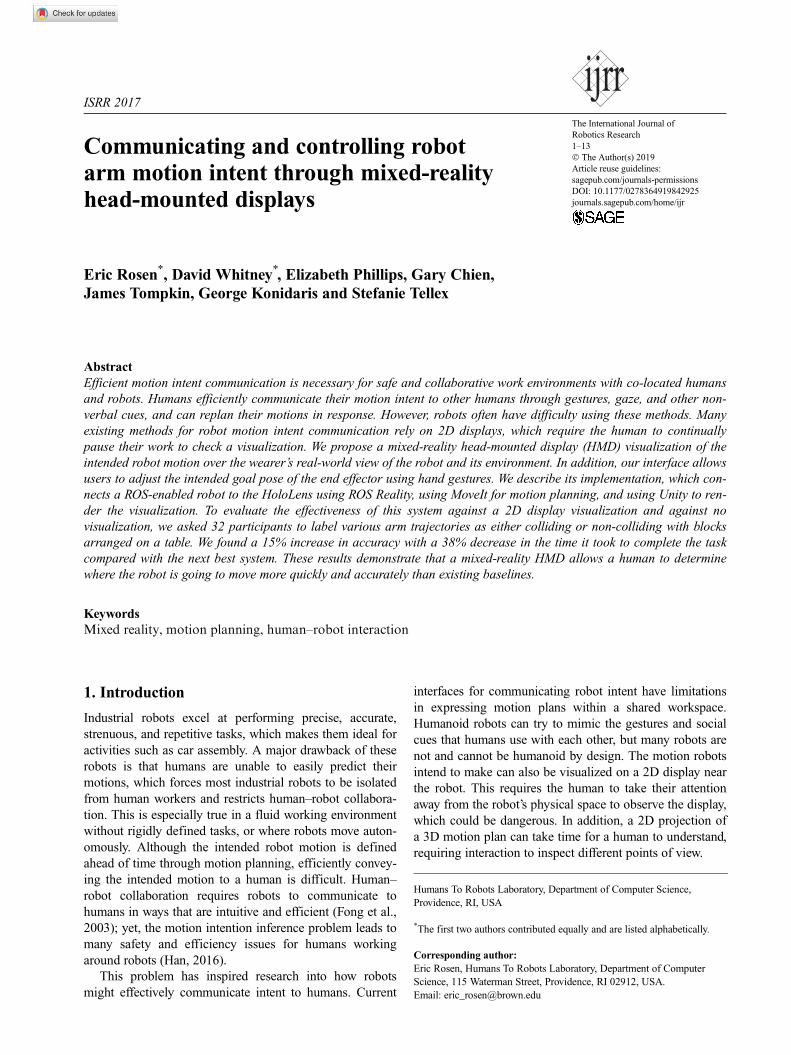
Fig. 1. An image captured directly from the MR Headset of a
user viewing a robot trajectory.
2 The International Journal of Robotics Research 00(0)
than collaborating with the robot (Burke and Murphy,
2004; Burke et al., 2004).
2.1. Augmented reality and MR for human–robot
collaboration
We can adapt the real-world environment around the human–
robot collaboration to help indicate robot intent. One way is to
combine light projectors with object tracking software to build
a general-purpose augmented environment. This has been used
to convey shared work spaces, robot navigational intention,
and safety information (Ahn and Kim, 2016; Andersen et al.,
2016; Chadalavada et al., 2015). However, building special
purpose environments is time consuming and expensive, with
a requirement for controlled lighting conditions. Further, they
exhibit occlusions of the augmenting light from objects in the
environment, and limit the number of people able to see
perspective-correct graphics.
Hand-held tablets can allow participants to view a MR
of 3D graphics overlaid onto a camera feed of the real world
(Rekimoto, 1996). These types of approaches mediate the
issue of diverted attention that 2D displays suffer. However,
they limit the ability of the operator to use their hands while
working, and there is a mismatch in perspective between
the eyes of the human and the camera in the tablet.
Optical HMDs can overlay 3D graphics on top of the
real world from the point of view of the human. This has
been hypothesized to be a natural and transparent means of
robot intent communication, for instance, with the overlay
of future robot poses (Ruffaldi et al., 2016; Scassellati and
Hayes, 2014). Hopefully such a system would reduce
human–robot collaborative task time and produce fewer
errors. The recent introduction of the Microsoft HoloLens
has made off-the-shelf implementations of such a visualiza-
tion possible. Previously, the HoloLens and other MR inter-
faces have been used in human–human collaboration, such
as communicating with remote companions and playing
adversarial games (Chen et al., 2015; Kato and
Billinghurst, 1999; Ohshima et al., 1998). However, MR as
a tool to communicate robot motion intent for human–
robot collaboration is nascent. Contemporary work investi-
gates the use of MR for communicating drone paths
(Walker et al., 2018), but there is a lack of work dealing
with multi-jointed, high-DoF robots. This inspired us to test
the hypothesis that a MR-HMD that allows participants to
see visual overlays on top of real-world environment in
human–robot collaborative tasks is an improvement over
existing approaches.
2.2. 3D spatial reasoning in virtual reality
displays
As HoloLens and its contemporaries are new as pieces of
integrated technology, there is little direct evidence to sup-
port their efficacy in robot intent communication. However,
hypotheses may be informed from literature in the parallel
technology of virtual reality (VR) which, in a similar way
to MR, provides head-tracked stereo display of 3D graphics
to create immersion. In VR, 3D spatial reasoning gains
have been tested (Slater and Sanchez-Vives, 2016). Pausch
et al. (1993) found that head-tracked displays outperform
stationary displays for a visual search task. Ware and
Franck (1994) found a head-tracked stereo display three
times less erroneous than a 2D display for visually asses-
sing graph connectivity. Slater et al. (1996) measured per-
formance gains in Tri-D chess for first-person perspective
VR HMDs over third-person perspective 2D displays (such
as RViz). Ruddle et al. (1999) found navigation through a
3D virtual building was faster using HMDs over 2D dis-
plays, though with no accuracy increase.
Not all experiments in this area favor large-format VR.
Many prior works compared immersive head-tracked
CAVE displays against desktop and ‘‘fishtank VR’’ dis-
plays, and often smaller higher-resolution displays induce
greater performance thanks to faster visual scanning
(Demiralp et al., 2006; Kasik et al., 2002). Santos et al.
(2009) reviewed all HMD to 2D display comparisons in
the literature until 2009, and found their results broadly
conflicting. Then, they conducted their own comparison for
3D navigation: on average, the desktop setup was better
than the VR HMDs.
In general, the relationship between VR display and task
performance is one with many confounding factors. The
benefits over traditional 2D desktop displays are task
dependent, and no clear prescriptive guidelines exist for
which techniques to employ to gain what benefit. As such,
while we may assume that a MR interface for viewing 3D
would be better, the evidence from the VR literature tells
us that the issue may be more complex.
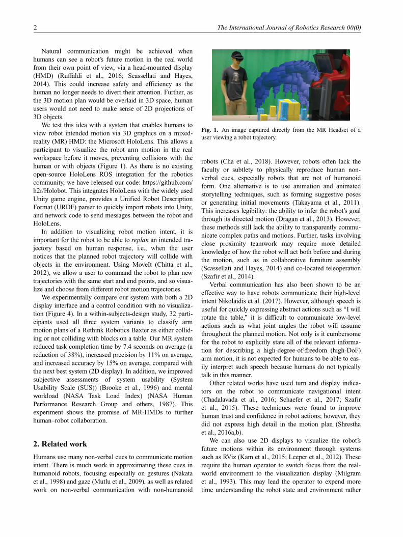
Fig. 2. A schematic of our system. Human operators use the
HoloLens to interact with a Unity scene using the
MixedRealityToolkit, and specify robot end-effector goal states
using hand gestures. Goal poses are wirelessly communicated
over rosbridge to a ROS network using ROS Reality. The MoveIt
node receives the goal pose and sends it to MoveIt, which uses
the current transform of the robot from /tf as the starting pose,
and publishes a plan onto /display_planned_path topic. This
motion plan is sent back over rosbridge to Unity, where the
TrajectoryVisualizer renders the trajectory fed from the
WebSocket client.
Rosen et al. 3
3. Technical approach
Communicating and controlling robot motion intent
requires us to join our robot control system (ROS with
ROS Reality) to a motion planner (MoveIt), and to visua-
lize the result on a MR-HMD (HoloLens with Unity) in a
shared robot/headset coordinate system.
3.1. ROS and ROS Reality
ROS (Quigley et al., 2009) is a set of tools and libraries to
help program robot applications. Designed for Linux sys-
tems, ROS connects robot hardware and program processes,
or nodes, via a local area network (LAN) or wireless local
area network (WLAN). Nodes communicate by streaming
data over channels, or topics. Nodes create publisher
objects to send data structures, or ROS messages, over dif-
ferent topics, or nodes create subscriber objects that manage
incoming publications on those topics. These nodes do not
need to be on the same computer as long as they can com-
municate over the ROS network. For example, the /robot_
state_publisher node runs on the robot. It subscribes to the
joint state topic, performs forward kinematics to calculate
the pose of each part of the robot in Cartesian coordinates,
and then publishes that information to the transform topic /
tf. Then, any device on the network can subscribe to /tf.
To visualize robot motion intent, the HoloLens needs to
interface with ROS to know upcoming robot poses. This pre-
sents a problem, as the HoloLens runs Windows 10, and
applications are created in the game engine Unity, neither of
which have built in support for ROS. To solve this issue, we
have created ROS Reality (Whitney et al., 2017), a software
package that enables the HoloLens to subscribe to and pub-
lish topics to a ROS network using WebSockets (see Figure
2). ROS Reality uses rosbridge (Toris et al., 2015) to open a
WebSocket connection between a server on the ROS network
and a client on the HoloLens. Messages are serialized to and
deserialized from JSON objects via ROS# (Bischoff, 2017),
which allows for easy creation of novel message types.
3.2. MoveIt
For robot motion planning, we use the MoveIt (Chitta et al.,
2012) software package, the most common motion plan-
ning software for ROS-enabled robots. Users are able to
programmatically specify start and goal robot transforms to
MoveIt from a ROS Node. With this, we need to both send
desired pose information from the HoloLens to MoveIt and
receive back motion plans to visualize.
To receive the planned trajectory from MoveIt, the
HoloLens directly subscribes to the /display_planned_path
ROS topic published by MoveIt. This topic contains a list
of time-stamped joint angles that determine the trajectory
visualization. To send poses to MoveIt, we send the poses
to an intermediary node on the ROS network called the
MoveIt Node (see Figure 2). This node receives the poses
from the HoloLens and uses MoveIt’s python API to create
a planning service request to MoveIt.
3.3. Microsoft HoloLens and Unity
The Microsoft HoloLens is a standalone MR headset that
allows users to overlay digital imagery on top of the real
world. This is accomplished with an inertial measurement
unit, an array of four cameras, and an infrared (IR) depth
sensor, which combine to simultaneously map the environ-
ment and locate the headset inside of that map. The
HoloLens supports the creation of MRs and gesture inter-
faces using the 3D game engine Unity (Unity Technologies,
2018) in conjunction with Microsoft’s MixedReality
Toolkit (MRTK) (Microsoft, 2017). Unity applications are
composed of scenes for human operators to interact within
a virtual space. Operators perceive the scene through the
MR headset and interact with it through hand gestures and
voice commands.
ROS Reality contains functions for generating realistic
Unity models of real ROS robots from URDFs. In addition,
ROS Reality allows the virtual robot model to mirror the live
robot, and vice versa. This provides natural situational and
environmental awareness of the robot, plus robot control.
3.4. Interaction walkthrough
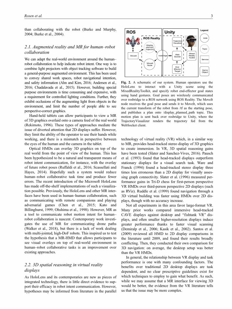
The flow of an interaction using our system can be seen in
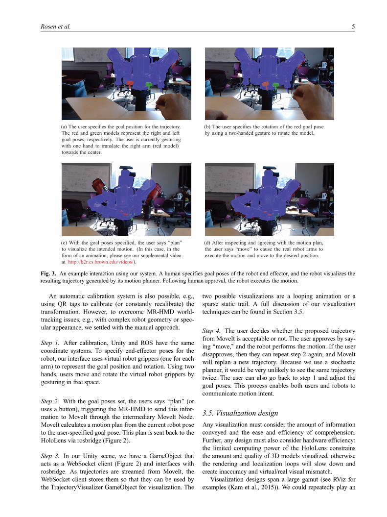
Figure 3 and the steps are as follows.
0. Once at startup: Manually calibrate the MR-HMD
coordinate system to the ROS coordinate system.
1. The user specifies a goal pose for each arm in the MR-
HMD using gestures (see Figures 3a and 3b).
2. Using speech, the user commands the MR-HMD to
send the goal poses to MoveIt via ROS Reality, which
computes a motion plan (Figure 3c). Again via ROS
Reality, this plan is sent back to the MR-HMD.
3. The human inspects the motion plan, visualized in the
MR-HMD via Unity.
4. If the user approves of the trajectory, then the robot
performs it (Figure 3d). If not, then the robot repeats
from step 2.
Step 0. To allow MR-HMD users to specify goal poses
and visualize plans in the same workspace as the robot, the
coordinate spaces of the virtual world in Unity and the real-
world robot must align. For this, we manually calibrate.
When the MR-HMD app is launched, a life-size virtual ver-
sion of the robot is displayed to the user. The MR-HMD
hand-tracking capabilities enable the user to ‘‘grab’’ the vir-
tual robot and align its position and rotation such that the
virtual robot is in the same place as the real robot. This
defines a rigid transformation between the two coordinate
spaces.
4 The International Journal of Robotics Research 00(0)
An automatic calibration system is also possible, e.g.,
using QR tags to calibrate (or constantly recalibrate) the
transformation. However, to overcome MR-HMD world-
tracking issues, e.g., with complex robot geometry or spec-
ular appearance, we settled with the manual approach.
Step 1. After calibration, Unity and ROS have the same
coordinate systems. To specify end-effector poses for the
robot, our interface uses virtual robot grippers (one for each
arm) to represent the goal position and rotation. Using two
hands, users move and rotate the virtual robot grippers by
gesturing in free space.
Step 2. With the goal poses set, the users says ‘‘plan’’ (or
uses a button), triggering the MR-HMD to send this infor-
mation to MoveIt through the intermediary MoveIt Node.
MoveIt calculates a motion plan from the current robot pose
to the user-specified goal pose. This plan is sent back to the
HoloLens via rosbridge (Figure 2).
Step 3. In our Unity scene, we have a GameObject that
acts as a WebSocket client (Figure 2) and interfaces with
rosbridge. As trajectories are streamed from MoveIt, the
WebSocket client stores them so that they can be used by
the TrajectoryVisualizer GameObject for visualization. The
two possible visualizations are a looping animation or a
sparse static trail. A full discussion of our visualization
techniques can be found in Section 3.5.
Step 4. The user decides whether the proposed trajectory
from MoveIt is acceptable or not. The user approves by say-
ing ‘‘move,’’ and the robot performs the motion. If the user
disapproves, then they can repeat step 2 again, and MoveIt
will replan a new trajectory. Because we use a stochastic
planner, it would be very unlikely to see the same trajectory
twice. The user can also go back to step 1 and adjust the
goal poses. This process enables both users and robots to
communicate motion intent.
3.5. Visualization design
Any visualization must consider the amount of information
conveyed and the ease and efficiency of comprehension.
Further, any design must also consider hardware efficiency:
the limited computing power of the HoloLens constrains
the amount and quality of 3D models visualized, otherwise
the rendering and localization loops will slow down and
create inaccuracy and virtual/real visual mismatch.
Visualization designs span a large gamut (see RViz for
examples (Kam et al., 2015)). We could repeatedly play an
Fig. 3. An example interaction using our system. A human specifies goal poses of the robot end effector, and the robot visualizes the
resulting trajectory generated by its motion planner. Following human approval, the robot executes the motion.
Rosen et al. 5
animation of the planned motion in real time, which conveys
all information but is slow to comprehend. We could show
all poses of the motion at once as a continuous trail, which
looks cluttered as it is somewhat redundant, and is computa-
tionally inefficient. At the other end, we could visualize only
the planned end-effector trail, which would be very efficient,
but would provide incomplete information on intermediate
arm joint locations which may collide with the world.
We drew inspiration from the visualization options pro-
vided in the RViz-based GUI to MoveIt. In that interface,
users can toggle between an animation of an arm moving
through the trajectory and a sparse stroboscopic trail made
of multiple arms sampled along the trajectory. For either
option, the virtual arm can either be the color of the real
robot, or a different, user-specified color.
We implement all of the discussed visualization options in
our package. Animation was initially our chosen technique,
as it most limits the number of needed draw calls compared
to the other options. Unfortunately, this comes at the expense
of user comprehension. In our initial testing, we found users
needed to watch the animation loop multiple times closely
inspect the entire trajectory. For our study, we settled on the
sparse trail option from RViz, with two major modifications.
First, we had to reduce the polygon count of our virtual arms
due to rendering bottlenecks on the HoloLens, and second,
we used a light-to-dark color gradient on the trail to empha-
size the direction of the motion plan (Figure 4).
4. Experiment
With our system, we can now test whether MR-HMDs can
aid motion intent communication between humans and
robots. We focused on robot-to-human communication,
and so goal pose adjustment was not evaluated in this study
as it pertains to human-to-robot communication. We asked
novice participants to decide whether or not a robot arm
motion plan would collide with blocks on a table using
three interfaces: no visualization, an RViz-like 2D display
visualization, and our MR visualization. Our evaluation
used 32 participants (15 male, 17 female) with ages rang-
ing from 20 to 55 (M = 26, SD = 6:8). We measured task
completion time and true-/false-positive/negative rates as
objective metrics, as well as the subjective assessments of
system usability, likability, and workload via the SUS and
NASA Task Load Index (TLX) questionnaires.
4.1. Task
In each interface, we presented each participant with the
same set of 14 robot arm motions in a random order. These
motions each moved from a start point to an end point over
a table covered in blocks. We did not allow users to specify
goal poses and used prerecorded trajectories of the robot’s
arm rather than use a motion planner in the loop to repeat-
edly present the same motions to each of the participants.
Unknown to the participant, exactly half of the motions col-
lided with the blocks and half did not. Each participant was
tasked with labeling the motions as either colliding or non-
colliding as quickly and accurately as possible. The blocks
were assembled such that it would be difficult to obtain a
complete view of all blocks from just one perspective owing
to occlusion from other blocks. Participants could walk
around to view the environment from different perspectives.
Once a participant had decided how to classify a particular
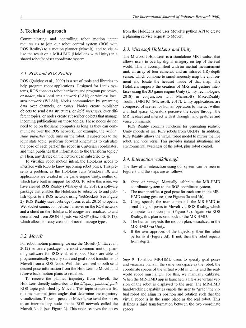
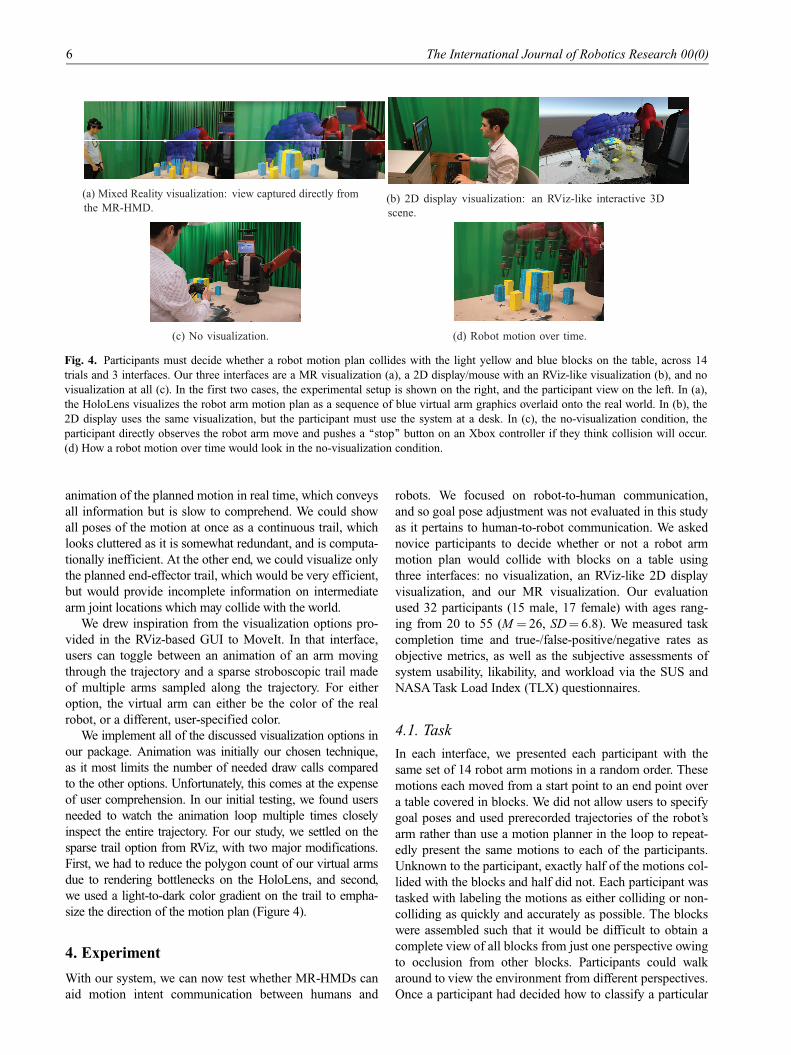
Fig. 4. Participants must decide whether a robot motion plan collides with the light yellow and blue blocks on the table, across 14
trials and 3 interfaces. Our three interfaces are a MR visualization (a), a 2D display/mouse with an RViz-like visualization (b), and no
visualization at all (c). In the first two cases, the experimental setup is shown on the right, and the participant view on the left. In (a),
the HoloLens visualizes the robot arm motion plan as a sequence of blue virtual arm graphics overlaid onto the real world. In (b), the
2D display uses the same visualization, but the participant must use the system at a desk. In (c), the no-visualization condition, the
participant directly observes the robot arm move and pushes a ‘‘stop’’ button on an Xbox controller if they think collision will occur.
(d) How a robot motion over time would look in the no-visualization condition.
6 The International Journal of Robotics Research 00(0)
motion, they pressed a button on an Xbox controller to indi-
cate their decision, allowing us to measure the time it took
for them to decide.
4.2. Interfaces
We compared three interfaces (Figure 4).
� No visualization. This simulated a participant supervis-
ing a robot with an emergency stop button. Participants
watched the arm, and pressed an Xbox controller but-
ton to stop the arm if they thought it would collide.� Monitor. Participants viewed and interacted with a 2D
monitor on a desk. The visualization consisted of: (1) a
3D model of the robot; (2) a sparse trail of its future
arm poses; and (3) a 3D point cloud of the environ-
ment, captured by a Kinect v2 sensor mounted near the
robot. In this interface, the robot arm did not move.
Participants could move the virtual camera in the visua-
lization to gain different perspectives using a keyboard-
and-mouse-based control scheme (the control scheme
was the same as in RViz (Kam et al., 2015)). The visua-
lization remained on the screen for the entire trial. For
consistency, participants again recorded their assess-
ment using an Xbox controller.� MR. Through a HoloLens, participants viewed the
same visualization of the motion plan overlaid on top
of the real world. In this case, there is no need to visua-
lize the environment via a point cloud because the par-
ticipant can see it directly. Users walked around the
room to change their perspective of the robot and visua-
lization. Like the other interfaces, participants decided
upon whether the motion collided or not, and recorded
their prediction using an Xbox controller. Like in the
monitor interface, the robot arm did not move, and the
visualizations remained for the entire trial.
Note that the no visualization interface differs from the
monitor and MR components because the arm moves. We
move the arm because asking the participant to judge
whether the arm will collide in the future with no clues
whatsoever is pure guesswork. However, moving the arm
makes it less comparable to the visualization components,
especially in the case of measuring task time. Given that
our main interest was to evaluate the effectiveness of the
MR-based visualization, we consider the no-visualization
interface to be a less-direct comparison than the monitor.
4.3. Experimental procedure
We began by reading a consent document to the partici-
pant. After consenting, participants completed our motion
intent task using all three interfaces. The no-visualization
condition was always completed before the other two inter-
faces. Participants received instruction to hit the stop button
if and only if they thought the arm was going to collide
with a tower. Then, after a 3–2–1 countdown, we started
the arm moving.
The monitor and MR interfaces then followed. We coun-
terbalanced the order in which participants completed the
monitor and MR conditions after completing the no-
visualization condition (i.e., half of participants completed
the no-visualization condition followed by the MR condi-
tion and then the monitor condition, the other half of parti-
cipants completed the no-visualization condition followed
by the monitor condition and then the MR condition).
Participants were randomly assigned to complete one of
the two counterbalancing conditions. For the MR and mon-
itor conditions, participants received instructions to label
the robot’s planned motion as quickly and accuracy as pos-
sible. Then, after a 3–2–1 countdown, we displayed the
visualization. After completing the task for all 14 robot
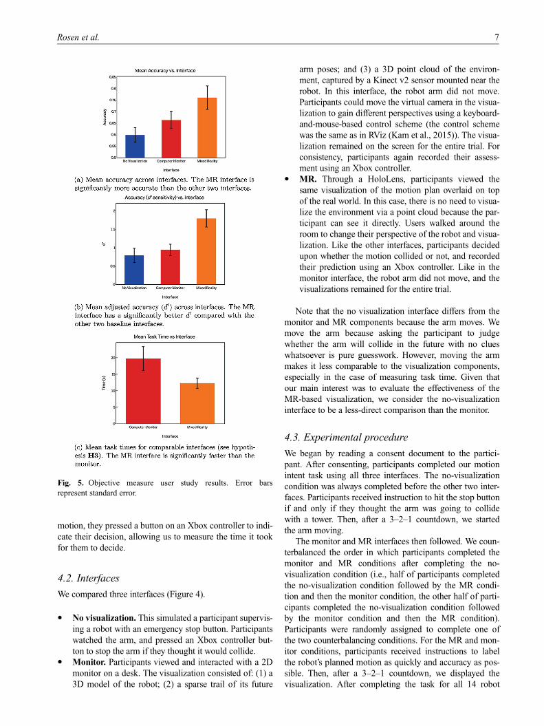
Fig. 5. Objective measure user study results. Error bars
represent standard error.
Rosen et al. 7
arm motions with each interface, the participant completed
three questionnaires.
4.4. Measurements
We chose the choice of interface as the within-subjects
independent variable. In all three interfaces, our objective
dependent variables were the true- and false-positive rates
of classifying a path as colliding, and the true- and false-
negative rates of classifying a path as non-colliding. By
using the mean adjusted accuracy (d0) metric, we also
accounted for participant strategy in labeling each motion
as colliding or non-colliding (e.g., showing a tendency to
always label a motion plan as colliding). This is discussed
further in Section 4.6.1.
In the monitor and MR interface conditions, we also
measured the average speed of labeling each motion plan
by recording the time elapsed from first seeing the visuali-
zation of the planned path to labeling the path. This allowed
us to measure the accuracy and precision with which each
interface allowed participants to label the robot’s intended
motion.
Our subjective dependent variables were participant
workload as measured by the NASA-TLX questionnaire
(NASA Human Performance Research Group and others,
1987), system usability as measured by the SUS question-
naire (Brooke et al., 1996), and our own questionnaire
measuring perceived predictability and preference for each
interface.
� NASA-TLX. This is a widely used assessment ques-
tionnaire that asks participants to provide a rating
of their perceived workload during a task across six
sub-scales: mental demand, physical demand, temporal
demand, effort, frustration, and performance. We mea-
sured the first five on scales from 0 (low) to 100 (high),
with performance measured from 0 (perfect) to 100
(failure). For this evaluation, the weighted measure of
paired comparisons among the sub-scales was not
included. The workload score is calculated as the aver-
age of the six sub-scales.� SUS. This questionnaire assesses overall system usabil-
ity by asking participants to rate ten statements on a
seven-point Likert scale ranging from ‘‘strongly dis-
agree’’ to ‘‘strongly agree.’’ The statements cover differ-
ent aspects of the system, such as complexity,
consistency, and cumbersomeness. SUS is measured
on a scale from 0 to 100, where 0 is the worst score
and 100 is the best.� Ours. This assessed how participants felt each inter-
face helped them to accurately predict collisions.
Participants were asked to rate three statements, one
for each condition, on a seven-point Likert scale rang-
ing from ‘‘strongly disagree’’ to ‘‘strongly agree.’’ For
instance, ‘‘When using the monitor and keyboard, I felt
I could accurately predict collisions.’’ We also asked
participants to select which interface they enjoyed the
most, which interface made understanding the robot’s
motion the easiest, and which interface they preferred
for completing the task.
4.5. Hypotheses
We expected that participants would show the best perfor-
mance in the MR interface condition followed by the moni-
tor interface (i.e., most true positives/negatives, fewest false
positives/negatives, lowest levels of mental workload, high-
est usability, predictability, and system preference scores).
In addition, we hypothesize that participants would have a
faster labeling speed with the MR interface compared with
the monitor interface.
� H1. MR will be the easiest interface for completing the
motion labeling task, as demonstrated by participants
achieving the best performance out of the three condi-
tions, across (a) most true positives/negatives, (b) few-
est false positives/negatives, (c) lowest levels of
workload, (d) highest usability scores, and (e) highest
predictability and preference scores.� H2. The monitor interface will be easier for completing
this task than using no visualization at all. This will be
demonstrated by participants achieving better perfor-
mance than with no visualization, across (a) more true
positives/negatives, (b) fewer false positives/negatives,
(c) lower levels of workload, (d) higher usability scores,
and (e) higher predictability and preference scores.� H3. The MR interface will have faster labeling times
than the monitor interface, as demonstrated by the aver-
age time it took for participants to label each motion as
colliding or not colliding. Labeling times in the moni-
tor and MR conditions are a function of evaluating the
visualization of the planned robot motion, whereas in
the no-visualization condition, labeling times are gener-
ated by watching the robot enact the planned motion.
As such, only the monitor and MR conditions are
directly comparable.
4.6. Results
4.6.1. Analysis techniques. We used repeated-measures
analysis of variance (ANOVA) and signal detection theory
(SDT) to determine whether differences between measures
in the three conditions were significant at the 95% confi-
dence level. Whereas ANOVA is likely to be familiar to the
reader, SDT is less likely to be familiar, and so we describe
its use.
SDT describes accuracy in human perception and
decision-making tasks by taking into account preferences
for responses (Macmillan, 2002; Tanner and Swets, 1954).
For instance, in our task, always responding that a motion
plan will collide would yield high true positive scores
(‘‘hits’’), and also high false-positive scores (‘‘false
alarms’’). In decision-making tasks with innocuous false
alarms, adopting this strategy would not affect overall
8 The International Journal of Robotics Research 00(0)
performance. However, for tasks with high false-alarm cost,
a strategy that results in low false-alarm rates while retain-
ing high hit rates is better. For human–robot interaction
tasks such as ours, false alarms would slow the collabora-
tion considerably and so we consider them high cost.
In SDT tasks, d0 (also called sensitivity) is a common
measure which considers decision-making strategy. It is the
standardized difference between the hit rate and the false-
alarm rate. To handle perfect scores (i.e., correctly labeling
all the colliding and non-colliding paths), zero false-alarm
scores, and zero hit scores, we adopted the technique out-
lined by Stanislaw and Todorov (1999).
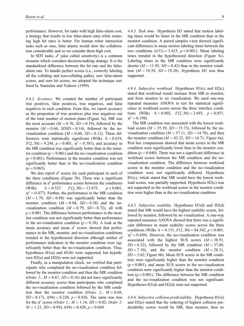
4.6.2. Accuracy. We counted the number of participant
true positives, false positives, true negatives, and false
negatives in each condition. From this, we report accuracy
as the proportion of true positives plus true negatives out
of the total number of motion plans (Figure 5a). MR was
the most accurate (M = 0:76, SD = 0:19), followed by the
monitor (M = 0:66, SDSD = 0:14), followed by the no-
visualization condition (M = 0:60, SD = 0:12). These dif-
ferences were statistically significant (Wilks L = 0:619,
F(2, 30)= 9:244, p = 0:001, h2 = 0:381), and accuracy in
the MR condition was significantly better than in the moni-
tor condition (p = 0:001) and the no-visualization condition
(p\0:001). Performance in the monitor condition was not
significantly better than in the no-visualization condition
(p = 0:065).
We also report d0 scores for each participant in each of
the three conditions (Figure 5b). There was a significant
difference in d0 performance scores between the conditions
(Wilks L = 0:523 F(2, 30)= 13:675, p\0:001,
h2 = 0:477). Further, the performance in the MR condition
(M = 1:79, SD = 0:88) was significantly better than the
monitor condition (M = 0:94, SD = 0:58) and the no-
visualization condition (M = 0:79, SD = 0:72), all with
p\0:001. The difference between performance in the mon-
itor condition was not significantly better than performance
in the no-visualization condition (p = 0:38). A look at the
mean accuracy and mean d0 scores showed that perfor-
mance in the MR, monitor, and no-visualization conditions
trended in the hypothesized direction although neither of
performance indicators in the monitor condition were sig-
nificantly better than the no-visualization condition. Thus,
hypotheses H1(a) and H1(b) were supported, but hypoth-
eses H2(a) and H2(b) were not supported.
Finally, as a manipulation check, we verified that parti-
cipants who completed the no-visualization condition fol-
lowed by the monitor condition and then the MR condition
(Order 1:, M = 0:67, SD = 0:16) did not have significantly
different accuracy scores than participants who completed
the no-visualization condition followed by the MR condi-
tion then the monitor condition (Order 2:, M = 0:68,
SD = 0:17), t(94)= 0:220, p = 0:826. The same was true
for the d0 scores (Order 1:, M = 1:14, SD = 0:82; Order 2:
M = 1:21, SD = 0:89), t(94)= 0:428, p = 0:669.
4.6.3. Task time. Hypothesis H3 stated that motion label-
ing times would be faster in the MR condition than in the
monitor condition. A paired samples t-test showed signifi-
cant differences in mean motion labeling times between the
two conditions (t(31)= 3:415, p\0:001). Mean labeling
times trended in the hypothesized direction (Figure 5c).
Labeling times in the MR condition were significantly
shorter (M = 11:95, SD = 8:42) than in the monitor condi-
tion (M = 19:39, SD = 19:28). Hypothesis H3 was thus
supported.
4.6.4. Subjective workload. Hypotheses H1(c) and H2(c)
stated that workload would increase from MR to monitor,
and from monitor to no visualization. We used one-way
repeated measures ANOVA to test for statistical signifi-
cance in workload scores across the three interface condi-
tions (Wilks L = 0:802, F(2, 30)= 3:693, p = 0:037,
h2 = 0:198).
The MR condition was associated with the lowest work-
load scores (M = 35:39, SD = 15:73), followed by the no-
visualization condition (M = 37:11, SD = 14:78), and then
the monitor condition (M = 42:32, SD = 14:71; Figure 6a).
Post hoc comparisons showed that mean scores in the MR
condition were significantly lower than in the monitor con-
dition (p = 0:040). There was not a significant difference in
workload scores between the MR condition and the no-
visualization condition. The difference between workload
scores in the monitor condition and the no-visualization
condition were not significantly different. Hypothesis
H1(c), which stated that MR would have the lowest work-
load scores, was partially supported. Hypothesis H2(c) was
not supported as the workload scores in the monitor condi-
tion were higher than in the no-visualization condition.
4.6.5. Subjective usability. Hypotheses H1(d) and H2(d)
stated that MR would have the highest usability scores, fol-
lowed by monitor, followed by no visualization. A one-way
repeated measures ANOVA showed that there was a signifi-
cant difference in mean usability scores across the three
conditions (Wilks L = 0:151, F(2, 30)= 84:342, p\0:001,
h2 = 0:849). However, the no-visualization condition was
associated with the highest SUS scores (M = 38:91,
SD = 6:52), followed by the MR condition (M = 37:88,
SD = 7:10), and the monitor condition (M = 28:31,
SD = 5:62; Figure 6b). Mean SUS scores in the MR condi-
tion were significantly higher than the monitor condition
(p\0:001), and mean SUS scores in the no-visualization
condition were significantly higher than the monitor condi-
tion (p\0:001). The difference between the MR condition
and the no-visualization condition was not significant.
Hypotheses H1(d) and H2(d) were not supported.
4.6.6. Subjective collision predictability. Hypotheses H1(e)
and H2(e) stated that the ordering of highest collision pre-
dictability scores would be MR, then monitor, then no
Rosen et al. 9
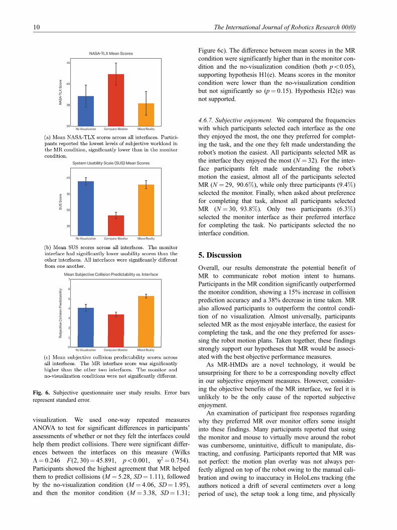
visualization. We used one-way repeated measures
ANOVA to test for significant differences in participants’
assessments of whether or not they felt the interfaces could
help them predict collisions. There were significant differ-
ences between the interfaces on this measure (Wilks
L = 0:246 F(2, 30)= 45:891, p\0:001, h2 = 0:754).
Participants showed the highest agreement that MR helped
them to predict collisions (M = 5:28, SD = 1:11), followed
by the no-visualization condition (M = 4:06, SD = 1:95),
and then the monitor condition (M = 3:38, SD = 1:31;
Figure 6c). The difference between mean scores in the MR
condition were significantly higher than in the monitor con-
dition and the no-visualization condition (both p\0:05),
supporting hypothesis H1(e). Means scores in the monitor
condition were lower than the no-visualization condition
but not significantly so (p = 0:15). Hypothesis H2(e) was
not supported.
4.6.7. Subjective enjoyment. We compared the frequencies
with which participants selected each interface as the one
they enjoyed the most, the one they preferred for complet-
ing the task, and the one they felt made understanding the
robot’s motion the easiest. All participants selected MR as
the interface they enjoyed the most (N = 32). For the inter-
face participants felt made understanding the robot’s
motion the easiest, almost all of the participants selected
MR (N = 29, 90:6%), while only three participants (9:4%)
selected the monitor. Finally, when asked about preference
for completing that task, almost all participants selected
MR (N = 30, 93:8%). Only two participants (6:3%)
selected the monitor interface as their preferred interface
for completing the task. No participants selected the no
interface condition.
5. Discussion
Overall, our results demonstrate the potential benefit of
MR to communicate robot motion intent to humans.
Participants in the MR condition significantly outperformed
the monitor condition, showing a 15% increase in collision
prediction accuracy and a 38% decrease in time taken. MR
also allowed participants to outperform the control condi-
tion of no visualization. Almost universally, participants
selected MR as the most enjoyable interface, the easiest for
completing the task, and the one they preferred for asses-
sing the robot motion plans. Taken together, these findings
strongly support our hypotheses that MR would be associ-
ated with the best objective performance measures.
As MR-HMDs are a novel technology, it would be
unsurprising for there to be a corresponding novelty effect
in our subjective enjoyment measures. However, consider-
ing the objective benefits of the MR interface, we feel it is
unlikely to be the only cause of the reported subjective
enjoyment.
An examination of participant free responses regarding
why they preferred MR over monitor offers some insight
into these findings. Many participants reported that using
the monitor and mouse to virtually move around the robot
was cumbersome, unintuitive, difficult to manipulate, dis-
tracting, and confusing. Participants reported that MR was
not perfect: the motion plan overlay was not always per-
fectly aligned on top of the robot owing to the manual cali-
bration and owing to inaccuracy in HoloLens tracking (the
authors noticed a drift of several centimeters over a long
period of use), the setup took a long time, and physically
Fig. 6. Subjective questionnaire user study results. Error bars
represent standard error.
10 The International Journal of Robotics Research 00(0)
moving around the robot was difficult at times. Even so,
34% of participants reported that they liked that they could
freely move around the robot to see the planned motion,
and that this made determining whether or not collisions
would occur faster, easier, and more intuitive than when
using the monitor and mouse.
The subjective questionnaire responses offered mixed
but promising support for the MR condition. Although par-
ticipants working with the MR condition reported lower
workload than in the no-visualization condition, it was not
significantly lower, which offered only partial support for
hypothesis H1(c). The mean workload scores did trend in
the hypothesized direction as the MR condition had the
lowest workload scores overall, and the results suggests
that participants did not find the MR interface more taxing
than using no interface at all. Although participants rated
the no-visualization condition as slightly more usable than
the MR condition (counter to hypothesis H1(d)), the no-
visualization condition was not rated significantly more
usable. The similarity of SUS and NASA-TLX scores
between the no visualization and the MR condition was
somewhat surprising, as the interfaces are extremely differ-
ent. It is possible that the increased cognitive load of inter-
preting the MR visualizations was offset by the increase in
ease of task resulting from those visualizations.
Perhaps surprisingly, the monitor condition did not sig-
nificantly outperform the no-visualization condition for
both objective and subjective measures. Participant accu-
racy (and accuracy accounting for decision-making strat-
egy) was not significantly better, and when working with
the computer monitor, participants reported higher work-
load and lower assessments of usability than when working
with the no-visualization condition. Put another way, look-
ing at a robot with an emergency stop button in your hand
is about as simple an interface as you could build. Finally,
participants also reported the least agreement that the mon-
itor interface could help them to accurately predict robot
collisions. Thus, no part of hypothesis H2 was supported.
As a consideration for future work, our system only con-
siders one method of human–robot motion intention com-
munication, and alternative methods may prove effective.
MR can also be used to communicate other things in addi-
tion to motion intent, such as shared goals, needed objects,
or other aspects of robot state.
In addition, further user studies could be conducted to
evaluate the effectiveness of using the MR-HMD for com-
municating motion intent in scenarios with varying cost of
mistakes. In our study, we instructed users to label the tra-
jectories as quickly and accurately as possible, but did not
directly penalize the users for mislabeling the trajectories.
Real-world situations that have actual costs associated with
making mistakes may more heavily rely on having an inter-
face that has higher usability for conveying information.
Although this study evaluated the effectiveness of using
MR-HMDs for communicating robot motion intent, we did
not evaluate the use of our system for enabling users to
adjust trajectories, measuring the effectiveness of human-
to-robot communication. Future work will address different
methodologies of allowing end-users to interact directly
with the planned trajectories, such as the end-effector goal
pose specification described in Section 3.4, or perhaps a
broader system that allows for fine-grain and high-level
adjustment.
6. Conclusion
If robots and humans are to form fluid cooperative work
partnerships, we will need efficient communication and
control of robot motion. We describe a system to allow MR
visualizations of robotic motion intent, an interface to con-
trol robot motion using MR, and a user study investigating
the hypothesis that MR would be a natural interface for
robot motion intent communication. In this study, we found
that both participant performance and participant percep-
tions were improved with an MR visualization over the
more traditional monitor interface for visualization and over
no visualization at all. Our results provide evidence that
MR is one way to bridge the robot–human motion commu-
nication gap.
Acknowledgment
We thank David Laidlaw for fruitful discussion on VR literature.
Funding
This work was supported by DARPA (grant number
D15AP00102) and by the AFRL (grant number FA9550-17-1-
0124). Any opinions, findings, and conclusions or recommenda-
tions expressed in this material are those of the authors and do not
necessarily reflect the views of DARPA or AFRL.
References
Ahn Jg and Kim GJ (2016) Remote collaboration using a tele-
presence mobile projector robot tele-operated by a smartphone.
In: IEEE/SICE International Symposium on System Integration
(SII). IEEE, pp. 236–241.
Andersen RS, Madsen O, Moeslund TB and Amor HB (2016)
Projecting robot intentions into human environments. In: Robot
and Human Interactive Communication (RO-MAN). IEEE, pp.
294–301.
Bischoff M (2017) ROS Sharp. https://github.com/siemens/ros-
sharp.
Brooke J, et al. (1996) SUS - a quick and dirty usability scale.
Usability Evaluation in Industry 189(194): 4–7.
Burke JL and Murphy RR (2004) Situation awareness and task
performance in robot-assisted technical search: Bujold goes to
Bridgeport. Technical Report CRASAR-TR2004-23, Center
for Robot-Assisted Search and Rescue, Tampa, FL.
Burke JL, Murphy RR, Coovert MD and Riddle DL (2004) Moon-
light in Miami: field study of human–robot interaction in the
context of an urban search and rescue disaster response train-
ing exercise. Human–Computer Interaction 19(1–2): 85–116.
Rosen et al. 11
Cha E, Kim Y, Fong T, Mataric MJ, et al. (2018) A survey of non-
verbal signaling methods for non-humanoid robots. Founda-
tions and Trends in Robotics 6(4): 211–323.
Chadalavada RT, Andreasson H, Krug R and Lilienthal AJ (2015)
That’s on my mind! Robot to human intention communication
through on-board projection on shared floor space. In: Eur-
opean Conference on Mobile Robots (ECMR). IEEE, pp. 1–6.
Chadalavada RT, Lilienthal A, Andreasson H and Krug R (2016)
Empirical evaluation of human trust in an expressive mobile
robot. In: RSS Workshop on Social Trust in Autonomous
Robots.
Chen H, Lee AS, Swift M and Tang JC (2015) 3D collaboration
method over HoloLens and Skype end points. In: Proc. 3rd
International Workshop on Immersive Media Experiences.
New York: ACM Press, pp. 27–30.
Chitta S, Sucan I and Cousins S (2012) MoveIt! IEEE Robotics
and Automation Magazine 19(1): 18–19.
Demiralp C, Jackson CD, Karelitz DB, Zhang S and Laidlaw DH
(2006) Cave and fishtank virtual-reality displays: A qualitative
and quantitative comparison. IEEE Transactions on Visualiza-
tion and Computer Graphics 12(3): 323–330.
Dragan AD, Lee KC and Srinivasa SS (2013) Legibility and pre-
dictability of robot motion. In: 2013 8th ACM/IEEE Interna-
tional Conference on Human–Robot Interaction (HRI). IEEE,
pp. 301–308.
Fong T, Nourbakhsh I and Dautenhahn K (2003) A survey of
socially interactive robots. Robotics and Autonomous Systems
42(3): 143–166.
Han Y (2016) The Social Behavior Guide for Confused Autono-
mous Machines. Master’s Thesis, Rhode Island School of
Design. https://issuu.com/horatiohan/docs/the_soical_behavior_
guide_for_confu
Kam HR, Lee SH, Park T and Kim CH (2015) RViz: A toolkit for
real domain data visualization. Telecommunication Systems
60(2): 337–345.
Kasik DJ, Troy JJ, Amorosi SR, Murray MO and Swamy SN
(2002) Evaluating graphics displays for complex 3D models.
IEEE Computer Graphics and Applications 22(3): 56–64.
Kato H and Billinghurst M (1999) Marker tracking and HMD cali-
bration for a video-based augmented reality conferencing sys-
tem. In: IEEE and ACM International Workshop on Augmented
Reality (IWAR). IEEE, pp. 85–94.
Leeper AE, Hsiao K, Ciocarlie M, Takayama L and Gossow D
(2012) Strategies for human-in-the-loop robotic grasping. In:
Proceedings of the seventh annual ACM/IEEE international
conference on Human-Robot Interaction. New York: ACM
Press, pp. 1–8.
Macmillan NA (2002) Signal detection theory. Stevens’ Handbook
of Experimental Psychology. New York: John Wiley & Sons,
Inc.
Microsoft (2017) MixedRealityToolKit. https://github.com/Micro
soft/MixedRealityToolkit-Unity
Milgram P, Zhai S, Drascic D and Grodski J (1993) Applications
of augmented reality for human–robot communication. In:
IEEE/RSJ International Conference on Intelligent Robots and
Systems (IROS), Vol. 3. IEEE, pp. 1467–1472.
Mutlu B, Yamaoka F, Kanda T, Ishiguro H and Hagita N (2009)
Nonverbal leakage in robots: Communication of intentions
through seemingly unintentional behavior. In: ACM/IEEE
International Conference on Human Robot interaction. New
York: ACM Press, pp. 69–76.
Nakata T, Sato T, Mori T and Mizoguchi H (1998) Expression of
emotion and intention by robot body movement. In: Interna-
tional Conference on Autonomous Systems.
NASA Human Performance Research Group and others (1987)
Task Load Index (NASA-TLX) v1.0 Computerised Version.
NASA Ames Research Centre.
Nikolaidis S, Kwon M, Forlizzi J and Srinivasa S (2017) Planning
with verbal communication for human–robot collaboration.
arXiv preprint arXiv:1706.04694.
Ohshima T, Satoh K, Yamamoto H and Tamura H (1998) AR2
Hockey: A case study of collaborative augmented reality. In:
Proceedings IEEE 1998 Virtual Reality Annual International
Symposium, 1998. IEEE, pp. 268–275.
Pausch R, Shackelford MA and Proffitt D (1993) A user study
comparing head-mounted and stationary displays. In: Proceed-
ings IEEE 1993 Symposium on Research Frontiers in Virtual
Reality, 1993. IEEE, pp. 41–45.
Quigley M, Conley K, Gerkey B, et al. (2009) ROS: An open-
source robot operating system. In: ICRA Workshop on Open
Source Software, Vol. 3, Kobe, Japan, p. 5.
Rekimoto J (1996) Transvision: A hand-held augmented reality
system for collaborative design. Virtual Systems and Multime-
dia 96: 18–20.
Ruddle RA, Payne SJ and Jones DM (1999) Navigating large-
scale virtual environments: What differences occur between
helmet-mounted and desk-top displays? Presence: Teleopera-
tors and Virtual Environments 8(2): 157–168.
Ruffaldi E, Brizzi F, Tecchia F and Bacinelli S (2016) Third point
of view augmented reality for robot intentions visualization.
In: International Conference on Augmented Reality, Virtual
Reality and Computer Graphics. Berlin: Springer, pp. 471–
478.
Santos BS, Dias P, Pimentel A, et al. (2009) Head-mounted dis-
play versus desktop for 3D navigation in virtual reality: A user
study. Multimedia Tools and Applications 41(1): 161.
Scassellati B and Hayes B (2014) Human–robot collaboration. AI
Matters 1(2): 22–23.
Schaefer KE, Straub ER, Chen JY, Putney J and Evans A (2017)
Communicating intent to develop shared situation awareness
and engender trust in human–agent teams. Cognitive Systems
Research 46: 26–39.
Shrestha MC, Kobayashi A, Onishi T, et al. (2016a) Intent com-
munication in navigation through the use of light and screen
indicators. In: ACM/IEEE International Conference on Human
Robot Interaction. IEEE Press, pp. 523–524.
Shrestha MC, Kobayashi A, Onishi T, et al. (2016b) Exploring the
use of light and display indicators for communicating direc-
tional intent. In: Advanced Intelligent Mechatronics. IEEE, pp.
1651–1656.
Slater M, Linakis V, Usoh M and Kooper R (1996) Immersion,
presence, and performance in virtual environments: An experi-
ment with tri-dimensional chess. ACM Virtual Reality Software
and Technology 163: 72.
Slater M and Sanchez-Vives MV (2016) Enhancing our lives with
immersive virtual reality. Frontiers in Robotics and AI 3: 74.
Stanislaw H and Todorov N (1999) Calculation of signal detection
theory measures. Behavior Research Methods, Instruments,
and Computers 31(1): 137–149.
Szafir D, Mutlu B and Fong T (2014) Communication of intent in
assistive free flyers. In: ACM/IEEE International Conference
on Human–Robot Interaction. New York: ACM Press, pp.
358–365.
12 The International Journal of Robotics Research 00(0)
Szafir D, Mutlu B and Fong T (2015) Communicating directional-
ity in flying robots. In: ACM/IEEE International Conference
on Human–Robot Interaction. New York: ACM Press, pp. 19–
26.
Takayama L, Dooley D and Ju W (2011) Expressing thought:
Improving robot readability with animation principles. In:
International Conference on Human–Robot Interaction. New
York: ACM Press, pp. 69–76.
Tanner WP Jr and Swets JA (1954) A decision-making theory of
visual detection. Psychological Review 61(6): 401.
Toris R, Kammerl J, Lu DV, et al. (2015) Robot web tools: Effi-
cient messaging for cloud robotics. In: 2015 IEEE/RSJ Interna-
tional Conference on Intelligent Robots and Systems (IROS).
IEEE, pp. 4530–4537.
Unity Technologies (2018) Unity Software. https://unity.com
Walker M, Hedayati H, Lee J and Szafir D (2018) Communicating
robot motion intent with augmented reality. In: Proceedings of
the 2018 ACM/IEEE International Conference on Human-
Robot Interaction. New York: ACM Press, pp. 316–324.
Ware C and Franck G (1994) Viewing a graph in a virtual reality
display is three times as good as a 2D diagram. In: Proceedings
IEEE Symposium on Visual Languages, 1994. IEEE, pp. 182–
183.
Whitney D, Rosen E, Phillips E, Konidaris G and Tellex S (2017)
Comparing robot grasping teleoperation across desktop and
virtual reality with ROS Reality. In: International Symposium
on Robotics Research.
Rosen et al. 13