commissioning status of hefei light source -...
TRANSCRIPT
COMMISSIONING STATUS OF HEFEI LIGHT SOURCE*
Li Weimin on behalf of commissioning team, NSRL, USTC, Hefei, Anhui, P.R.China
Abstract The upgrade project of Hefei Light Source, which is
sponsored by CAS and USTC, is undergoing. The machine commissioning was started at the beginning of 2014. During 5 months, we have completed commissioning of electron linac, beam transfer line, storage ring and insertion devices. In this paper, the commissioning status and results of HLS were introduced briefly. Several problems were studied experimentally and analyzed. Generally speaking, the performance of HLS is agreement with expectations.
INTRODUCTION Hefei Light Source is a dedicated VUV and soft X-ray
synchrotron radiation light source, which was designed and constructed originally in the nineteen-eighties. To enhance the performance of HLS, a major renovation project was started in July, 2010. The main contents of upgrade are implementation of full energy injection, reconstruction of storage ring magnet lattice and installation of new insertion devices. With lowered beam emittance and new insertion devices, the brilliance of HLSII will be stronger than that before. The new power supply system and beam instrumentation system should be helpful to improvement of stability and reliability of light source. The main performance parameters of HLSII were listed in table 1.
Table 1: Main Parameters of HLSII.
Injectors
Beam energy 800 MeV
Bunch length 1 ns
Bunch charge 1 nC
Energy spread 0.5%
Energy jitter 0.5%
Storage Ring
Beam energy 800 MeV
Natural emittance < 40nm.rad
Beam intensity 300 mA
1/e Beam lifetime > 5 hours
Slow orbit drifts < 0.1 σ
Number of Insertion devices 5
MILESTONES The upgrade project of HLS was launched in July, 2010.
At same time, the original machine was operated in user-mode until May, 2012. The main time nodes of project are as following. July, 2010, the formal starting point of upgrade
project. May. 2012, the removal of original machine,
including injector, storage ring, beamlines, etc. June, 2012, the decoration of infrastructure,
including linac tunnel, storage ring tunnel, and ring hall.
September, 2012, the installation of linac. January, 2013, the installation of storage ring. July, 2013, engineering of water cooling system, air
conditioning system and cable system. January, 2014, commissioning of linac injector. February, 2014, commissioning of storage ring, first
stored beam in storage ring. March, 2014, beam energy of injector reaches 800
MeV, stored beam intensity more than 300mA. April, 2014, BBA, COD correction, LOCO, multi-
bunch feedback commissioning for storage ring. June, 2014, operation of insertion devices. July, 2014, commissioning of beam lines.
INJECTOR The beam energy of old linac is 200 MeV, where 5
constant impedance travelling wave accelerating tubes were used. In the new injector, we use 8 constant gradient TW accelerating tubes, which are powered by 50MW klystrons with SLED system, and the maximum designed beam energy is 960 MeV. The second improvement is installation of new Beam Position Monitor system. With help of Libra single pass module, we can accurately monitor and control beam trajectory.
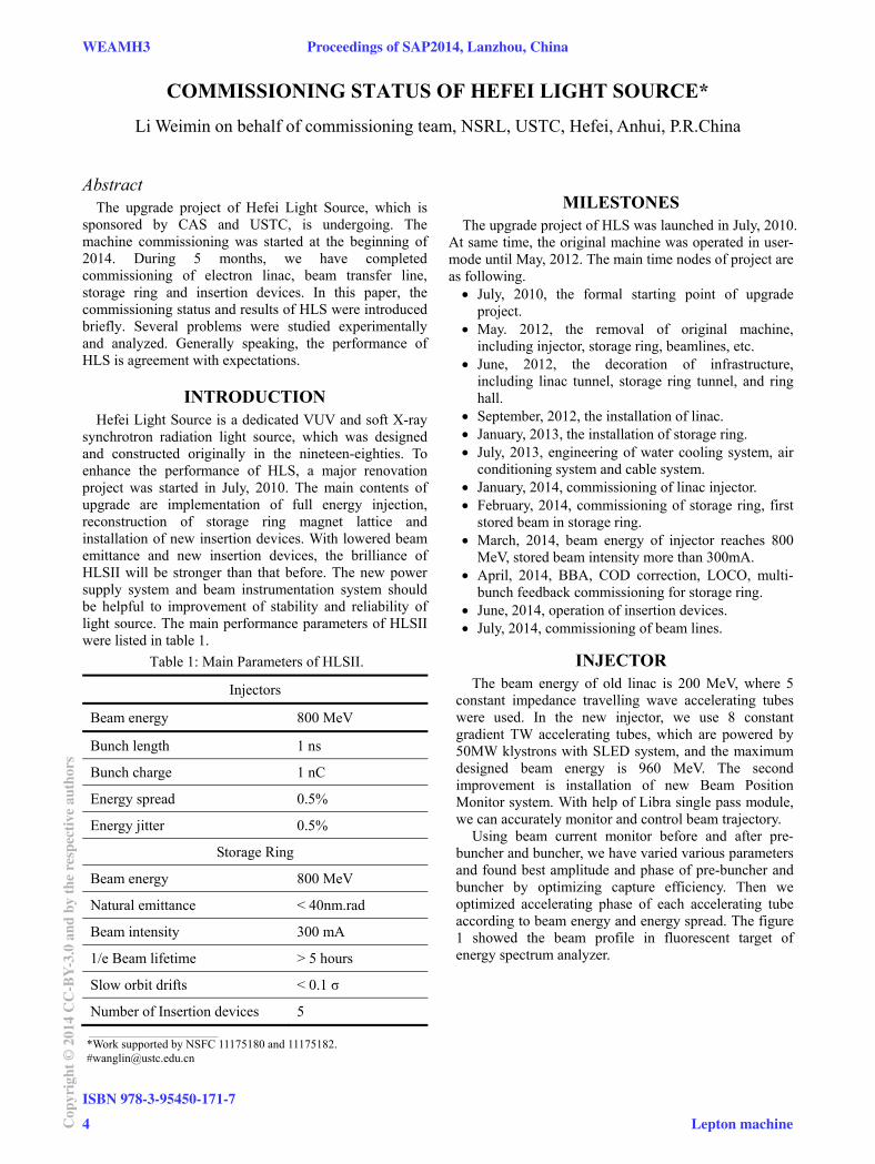
Using beam current monitor before and after pre-buncher and buncher, we have varied various parameters and found best amplitude and phase of pre-buncher and buncher by optimizing capture efficiency. Then we optimized accelerating phase of each accelerating tube according to beam energy and energy spread. The figure 1 showed the beam profile in fluorescent target of energy spectrum analyzer.
___________________________________________
*Work supported by NSFC 11175180 and 11175182. #[email protected]
WEAMH3 Proceedings of SAP2014, Lanzhou, China
ISBN 978-3-95450-171-7
4Cop
yrig
ht©
2014
CC
-BY-
3.0
and
byth
ere
spec
tive
auth
ors
Lepton machine
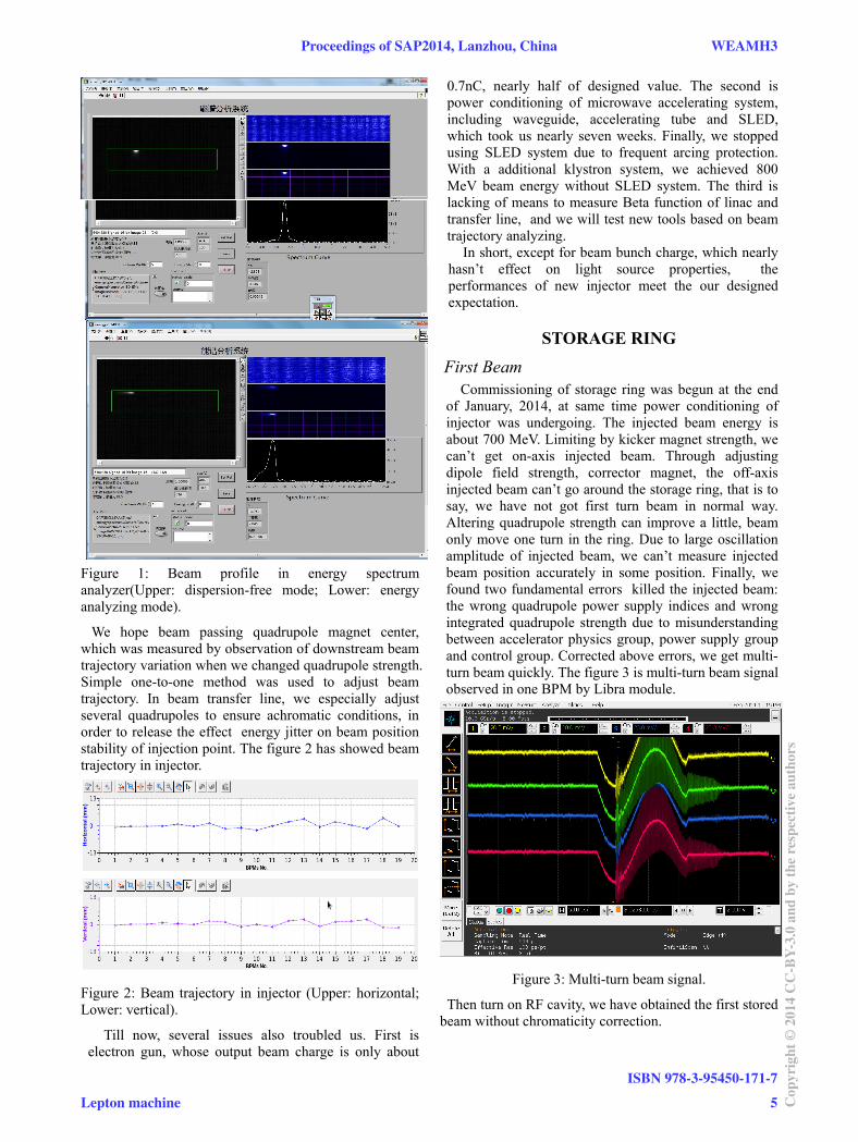
Figure 1: Beam profile in energy spectrum analyzer(Upper: dispersion-free mode; Lower: energy analyzing mode).
We hope beam passing quadrupole magnet center, which was measured by observation of downstream beam trajectory variation when we changed quadrupole strength. Simple one-to-one method was used to adjust beam trajectory. In beam transfer line, we especially adjust several quadrupoles to ensure achromatic conditions, in order to release the effect energy jitter on beam position stability of injection point. The figure 2 has showed beam trajectory in injector.
Figure 2: Beam trajectory in injector (Upper: horizontal; Lower: vertical).
Till now, several issues also troubled us. First is electron gun, whose output beam charge is only about
0.7nC, nearly half of designed value. The second is power conditioning of microwave accelerating system, including waveguide, accelerating tube and SLED, which took us nearly seven weeks. Finally, we stopped using SLED system due to frequent arcing protection. With a additional klystron system, we achieved 800 MeV beam energy without SLED system. The third is lacking of means to measure Beta function of linac and transfer line, and we will test new tools based on beam trajectory analyzing.
In short, except for beam bunch charge, which nearly hasn’t effect on light source properties, the performances of new injector meet the our designed expectation.
STORAGE RING
First Beam Commissioning of storage ring was begun at the end
of January, 2014, at same time power conditioning of injector was undergoing. The injected beam energy is about 700 MeV. Limiting by kicker magnet strength, we can’t get on-axis injected beam. Through adjusting dipole field strength, corrector magnet, the off-axis injected beam can’t go around the storage ring, that is to say, we have not got first turn beam in normal way. Altering quadrupole strength can improve a little, beam only move one turn in the ring. Due to large oscillation amplitude of injected beam, we can’t measure injected beam position accurately in some position. Finally, we found two fundamental errors killed the injected beam: the wrong quadrupole power supply indices and wrong integrated quadrupole strength due to misunderstanding between accelerator physics group, power supply group and control group. Corrected above errors, we get multi-turn beam quickly. The figure 3 is multi-turn beam signal observed in one BPM by Libra module.
Figure 3: Multi-turn beam signal.
Then turn on RF cavity, we have obtained the first stored beam without chromaticity correction.
Proceedings of SAP2014, Lanzhou, China WEAMH3
Lepton machine
ISBN 978-3-95450-171-7
5 Cop
yrig
ht©
2014
CC
-BY-
3.0
and
byth
ere
spec
tive
auth
ors

Increasing Beam Intensity First of all, we improve beam injection efficiency. We
optimized matching between four injection kicker magnets observing residual orbit oscillation of stored beam. According to beam injected speed, we varied injected beam position and angle, stored beam orbit and parameters of local bump system.
Then we measured and corrected storage ring chromaticities according to tune variation with RF frequency. We found over-positive chromaticities are helpful to enhance beam stability. Sweeping tuner position of passive 4th harmonic cavity, we found good tuner position, where beam is more stable. With above measures, the maximum stored single bunch current is above 100 mA.
We also measured the central frequency of storage ring, which is higher than designed value. The figure 4 showed the measured central frequency, which is agreement with the calculated path length according to alignment results.
204.015 204.02 204.025 204.03 204.035 204.04 204.0450.428
0.43
0.432
0.434
0.436
0.438
0.44
frf (MHz)
x
x Correct Chromaticities and Center Frequency
-1.276-0.32664 0.62865 1.5904
Figure 4: Measured central frequency.
BBA, Orbit and LOCO At March, 2014, with new additional klystron power
source, the injector energy was up raised to 800 MeV and we realized full energy injection of storage ring. Under normal operation condition, the optimization of storage ring parameters was main task.
Observing orbit variation when we adjust the individual quadrupole strength, we can know the quadrupole centre, which is named BBA procedure. The figure 5 showed one quadrupole centre measured procedure and quadrupole centre distribution around storage ring.
Based on BBA results, we have made closed orbit distortion correction. Using measured orbit response matrices, SVD method was used to COD correction, where we used 16 single value and the rms residual orbit distortion about 30 μm. The figure 6 is closed orbit distortion along the storage ring.
Measured orbit response matrix also used to optics correction by LOCO method. The fitted quadrupole strength correction may come from magnetic field measurement errors of quadrupole magnets or from
closed orbit distortion in sextupole magnets, etc. The figure 7 displayed the quadrupole strength correction along the storage ring. And the figure 8 showed the measured Beta function by delta-K method.
In this stage, the main trouble is reliability of BPM system. We have checked connection ports, cables, and modules in BPM system again and again and confirmed the reliability of BPM.
Model Independent Analysis was also used in optics analysis, whose results are agreement with other methods. But limiting Libra module in storage ring restricted MIA application at present time.
Figure 5: BBA results (Upper: BBA results of all quadrupoles; Lower: Measured date of one quadrupole).
Figure 6: Corrected closed orbit.
WEAMH3 Proceedings of SAP2014, Lanzhou, China
ISBN 978-3-95450-171-7
6Cop
yrig
ht©
2014
CC
-BY-
3.0
and
byth
ere
spec
tive
auth
ors
Lepton machine

Figure 7: Quadrupole strength correction.
Figure 8: Measured Beta function (upper) and dispersion function (lower).
Harmonic Cavity In HLS II storage ring, passive 4th harmonic cavity was
installed for improving beam lifetime. We have scanned tuner position of harmonic cavity and observed bunch length variation by streak camera. When the resonant frequency is lower than fourth RF harmonics, beam is more stable, but bunch length is shorter. While the resonant frequency is higher than fourth RF harmonics, bunch will be lengthened, at same time, strong longitudinal oscillation associated with horizontal beam blow-up maybe occurred. This longitudinal oscillation is associated with beam intensity and tuner position. Finally,
the operation mode of harmonic cavity is as following: at the low beam intensity, we fixed tuner position, while at high beam intensity, we fixed harmonic cavity voltage by changing tuner position.
Multi-bunch Feedback We can observe vertical and longitudinal oscillation
sidebands in beam spectrum. Adjusting transverse and longitudinal multi-bunch feedback system, the unstable beam oscillation signal can be suppressed effectively.
The figure 9 is beam performance without and with multi-bunch feedback system. With multi-bunch feedback, longitudinal oscillation sidebands and vertical beam blow-up were suppressed, horizontal beam oscillation was damped more quickly.
Figure 9: Beam spectrum with and without multi-bunch feedback system (Left: feedback off; Right: feedback on; Upper: longitudinal; Middle: horizontal; Lower: beam sizes)
Orbit Stability We have constructed heat-insulation tunnel for storage
ring to improve circumference temperature stability. At same time, constant temperature cooling system for main magnets of storage ring is more powerful than before. Especially, constant operation beam energy is essential to improve the stability of power supply system, which was optimized at small working range. Further, with slow orbit feedback control system, we can suppress slow horizontal and vertical orbit shifts to 5 μm level. The figure 10 showed the horizontal and vertical slow orbit shifts in a run. The figure 11 was the beam position variation in different runs.
Proceedings of SAP2014, Lanzhou, China WEAMH3
Lepton machine
ISBN 978-3-95450-171-7
7 Cop
yrig
ht©
2014
CC
-BY-
3.0
and
byth
ere
spec
tive
auth
ors
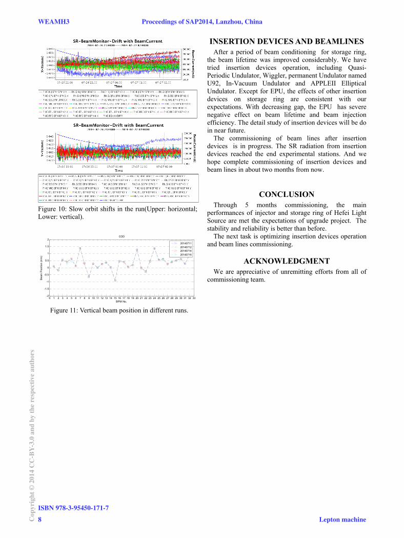
Figure 10: Slow orbit shifts in the run(Upper: horizontal; Lower: vertical).
0 1 2 3 4 5 6 7 8 9 10 11 12 13 14 15 16 17 18 19 20 21 22 23 24 25 26 27 28 29 30 31 32 33-2
-1.5
-1
-0.5
0
0.5
1
1.5
2
BPM No.
Bea
m P
ositi
on (m
m)
COD
20140711201407122014071420140716
Figure 11: Vertical beam position in different runs.
INSERTION DEVICES AND BEAMLINES After a period of beam conditioning for storage ring,
the beam lifetime was improved considerably. We have tried insertion devices operation, including Quasi-Periodic Undulator, Wiggler, permanent Undulator named U92, In-Vacuum Undulator and APPLEII Elliptical Undulator. Except for EPU, the effects of other insertion devices on storage ring are consistent with our expectations. With decreasing gap, the EPU has severe negative effect on beam lifetime and beam injection efficiency. The detail study of insertion devices will be do in near future.
The commissioning of beam lines after insertion devices is in progress. The SR radiation from insertion devices reached the end experimental stations. And we hope complete commissioning of insertion devices and beam lines in about two months from now.
CONCLUSION Through 5 months commissioning, the main
performances of injector and storage ring of Hefei Light Source are met the expectations of upgrade project. The stability and reliability is better than before.
The next task is optimizing insertion devices operation and beam lines commissioning.
ACKNOWLEDGMENT We are appreciative of unremitting efforts from all of
commissioning team.
WEAMH3 Proceedings of SAP2014, Lanzhou, China
ISBN 978-3-95450-171-7
8Cop
yrig
ht©
2014
CC
-BY-
3.0
and
byth
ere
spec
tive
auth
ors
Lepton machine