alignment throughout the upgrade engineering of hefei ... · • the upgrade engineering of hefei...
TRANSCRIPT

National Synchrotron Radiation Laboratory University of Science & Technology of China
Alignment throughout the Upgrade Engineering of Hefei Light Source
• HE Xiaoye, WANG Wei, YAO Qiuyang, TANG Zheng
National Synchrotron Radiation Laboratory University of Science and Technology of China

National Synchrotron Radiation Laboratory University of Science & Technology of China
• The upgrade engineering of Hefei Light Source is almost completed and the machine is being commissioned.
• This paper introduces the survey and alignment jobs that run throughout all the process of the engineering construction.

National Synchrotron Radiation Laboratory University of Science & Technology of China
• INTRODUCTION • ESTABLISHMENT, MEASUREMENT AND
DATA PROCESSING OF FIRST-LEVEL CONTROL NETWORK
• ESTABLISHMENT, MEASUREMENT AND DATA PROCESSING OF SECOND-LEVEL CONTROL NETWORK
• PRE-ALIGNMENT OF UNITS • ALIGNMENT DURING INSTALLATION • CONCLUSIONS • ACKNOWLEDGEMENT

National Synchrotron Radiation Laboratory University of Science & Technology of China
• The light source after upgraded is called HLSII and the project is called HLSII project.
• Purpose: provide users higher quality and efficiency of service.
• Measures: reduce the beam emittance and raise the luminance of the light source.

National Synchrotron Radiation Laboratory University of Science & Technology of China
Alignment work mainly includes: •Design and establish survey control network •Pre-align every unit before it is installed •Align units according to the locating data during installation
Alignment technologies: • 3D measurement instrumentations : laser tracker, total station, T-probe •Traditional optical instruments : optical level, Plummet .

National Synchrotron Radiation Laboratory University of Science & Technology of China
• INTRODUCTION • ESTABLISHMENT, MEASUREMENT AND
DATA PROCESSING OF FIRST-LEVEL CONTROL NETWORK
• ESTABLISHMENT, MEASUREMENT AND DATA PROCESSING OF SECOND-LEVEL CONTROL NETWORK
• PRE-ALIGNMENT OF UNITS • ALIGNMENT DURING INSTALLATION • CONCLUSIONS • ACKNOWLEDGEMENT

National Synchrotron Radiation Laboratory University of Science & Technology of China
• The first-level control network : Control the global position of the whole machine
• Based on the first phase project of Hefei Light source (HLS):
4 stationary points in the hall of storage ring (P1, P2, P3, P4) 4 points in the tunnel of transportation line and linac (P5, P6, P7, P8)

National Synchrotron Radiation Laboratory University of Science & Technology of China
Optical theodolite, level and total station can be set up directly on them which with forced centering devices
P5 was dismantled and a new and small ground
point TGA19 was used instead because of the requirement of civil engineering
P9 and LWB21, were added between P7 and P8 to increase the intensity of the control network
• Machine coordinate system: The origin: The intersection
of the diagonal lines of the square which is made of the four points P1, P2, P3 and P4
The line linking P1 and P3 is defined as X axis.

National Synchrotron Radiation Laboratory University of Science & Technology of China
• There are two layers of the building structure of the machine The storage ring is on the upper layer
The transportation line and linac line are in a tunnel which is on the lower layer located on semi-underground.
The difference in elevation of the two layers is near 3 meters.
• Two holes with diameters of 300 mm are made on the ceiling exactly above the points TGA19 and P6.
• TGA19 and P6 are plumbed on two interim targets on the ground of storage ring, which are TGA19’ and P6
National Synchrotron Radiation Laboratory University of Science & Technology of China
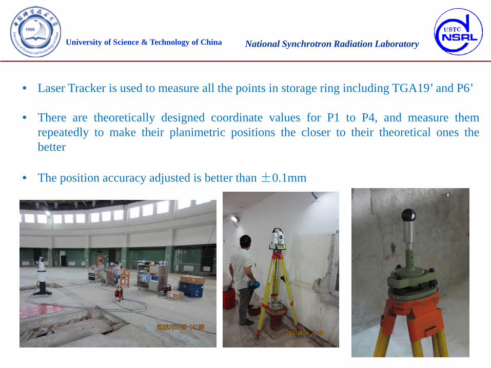
• Laser Tracker is used to measure all the points in storage ring including TGA19’ and P6’
• There are theoretically designed coordinate values for P1 to P4, and measure them repeatedly to make their planimetric positions the closer to their theoretical ones the better
• The position accuracy adjusted is better than ±0.1mm

National Synchrotron Radiation Laboratory University of Science & Technology of China
N3 optical level is used to measure the relative height of all the points.
The transfer measurements between the ring ground and tunnel are completed using a three meters’ rod through the holes above the P6 and TGA19.
National Synchrotron Radiation Laboratory University of Science & Technology of China
• The elevation data are processed by using the software COSA software, which developed by Wuhan University, and the SHANWEI, a commercial software.
• The data from laser tracker and total station are dealt with by separating the plan data (X, Y) and elevation data (Z).
• The two groups of data are done adjustment calculation respectively using the two kinds of software.
• The three-dimensional data from the calculated results will be used as the initial theoretical data for the machine position and the next levels control networks.

National Synchrotron Radiation Laboratory University of Science & Technology of China
• INTRODUCTION • ESTABLISHMENT, MEASUREMENT AND
DATA PROCESSING OF FIRST-LEVEL CONTROL NETWORK
• ESTABLISHMENT, MEASUREMENT AND DATA PROCESSING OF SECOND-LEVEL CONTROL NETWORK
• PRE-ALIGNMENT OF UNITS • ALIGNMENT DURING INSTALLATION • CONCLUSIONS • ACKNOWLEDGEMENT

National Synchrotron Radiation Laboratory University of Science & Technology of China
• The second-level control network is established for the installation of machine, the monitoring of deformation of machine after it is built and the alignment of new insert units. • Every point in the second-level control network possesses three-dimensional coordinate values by surveying and calculation. • It is obtained based on the first-level plane control network by adding more points • The points mainly distribute:
On the ground, building support columns, wall

National Synchrotron Radiation Laboratory University of Science & Technology of China
• Two aspects of measurement of the second-level control network:
Firstly, N3 optical level is used to measure the elevation of every point. The permanent reference point which was built during the first phase project is used as the elevation datum point Two measuring paths are ring closing mode. a. Using the holes on the ceiling of transportation line tunnel to do link measurement between storage ring and the tunnel b. Along the outside periphery of the buildings to do closing measurement. The measurement data are dealt with by COSA software
Secondly, Laser Tracker is used to measure all the points in linac and transportation line tunnel and storage ring. Every two neighboring stations must have more than 10 common measuring points and make them fly-over crossing as far as possible. In order to compensate the influences from environmental factors, laser tracker must measure the standard invar criterion meter (Scale Bar) at every station.

National Synchrotron Radiation Laboratory University of Science & Technology of China

National Synchrotron Radiation Laboratory University of Science & Technology of China
• The schedule of the project is very tight, and colleagues from Beijing Institute of High Energy (IHEP) and Lanzhou Institute of Modern Physics (IMP) were invited to participate the alignment work who brought a set of API Laser Tracker and a set of FARO one with them.
• There were three sets of different kind of laser trackers joining the work.
• So a lot of work to compare the accuracies among them was done before actual on-site alignment work began, which included their accuracy uniformities and compensation by environmental factors.
National Synchrotron Radiation Laboratory University of Science & Technology of China
• The measure data from the second-level control network were processed using the USMN function of SA software. Here the following points must be taken notice.
1.The data from laser trackers and the adjustment results of elevation data were dealt with by
USMN together and the elevation data would be given higher weight, 1000, for example. 2.Scale Bar measurement must be founded and do simulation measures of the two points of
the Scale Bar in the data. 3.During the calculation it is necessary to repeatedly prune some point data with large
deviation more than an expectant value by checking the Ranking column and generally the points with the ranking value more than 300% will be pruned and calculating again.
Afterwards uncertainty field is analyzed and calculated and the final processed data would be
the theoretical coordinate values of every point in the network and be used in the coming installation work.

National Synchrotron Radiation Laboratory University of Science & Technology of China
• INTRODUCTION • ESTABLISHMENT, MEASUREMENT AND
DATA PROCESSING OF FIRST-LEVEL CONTROL NETWORK
• ESTABLISHMENT, MEASUREMENT AND DATA PROCESSING OF SECOND-LEVEL CONTROL NETWORK
• PRE-ALIGNMENT OF UNITS • ALIGNMENT DURING INSTALLATION • CONCLUSIONS • ACKNOWLEDGEMENT

National Synchrotron Radiation Laboratory University of Science & Technology of China
• The work coordinate system when using laser tracker to do pre-alignment is based on instrument coordinate system
• After measuring some characteristic points or faces of units and by using some functions of matching software (SA,for example), a new coordinate system based on the unit character is built
• Under this system the targets on it would get their coordinate values which are basis for it being installed in machine.

National Synchrotron Radiation Laboratory University of Science & Technology of China
Pre-alignment of different magnets • Instruments include laser tracker, N3 and electronic inclinometer:
Choosing the lower pole face, front face and one side face as reference planes, by
measuring them and fitting, three standard planes of T-PLANE、E-PLANE and F-PLANE are gotten.
Defining the intersection of the three planes as the original point, the intersecting line of T-PLANE and F-PLANE as the Z axis and the normal direction of T-PLANE as the direction of Y axis,the unit coordinate system is structured.

National Synchrotron Radiation Laboratory University of Science & Technology of China
• A datum plate is welded on the top of dipole and electronical inclinometer is used to measure the roll and pitch. The readings are part of the pre-alignment date and used to guarantee the correct gesture

National Synchrotron Radiation Laboratory University of Science & Technology of China
• Quadrupole and Sextupole have the similar structure and the pre-alignment process is the same. Bearing bush is made, whose center line coincide the axis of the magnet and its two ends can be measure by laser tracker and the link of the two points is defined as the Z axis. Choosing the front plane and top plan as reference planes and measuring them and fitting, E-PLANE and T-PLANE are gotten. Defining the intersection of Z and E-PLANE as the original point, and the normal direction of T-PLANE as the direction of Y axis,the unit coordinate system is structured.

National Synchrotron Radiation Laboratory University of Science & Technology of China
Pre-alignment of accelerating tube
• The length of an accelerating tube is three meters and it is impossible to measure its whole outline at a station of laser tracker with ball target. T-Probe is used to pre-align accelerating tube
• Evenly measuring the surfaces of entrance flanges of accelerating tube and waveguide tube and fitting, two planes, the E-PLANE and T-PLANE are gotten.

National Synchrotron Radiation Laboratory University of Science & Technology of China
• Defining the axis of the CYLINDER, L0, as Z axis, the intersection of L0 and the E-PLANE as the original point and the normal direction of T-PLANE as the direction of X axis, the unit coordinate system is structured.
• Measuring sixty points which evenly distribute around the cylindrical surface of tube and fitting, the CYLINDER is gotten.

National Synchrotron Radiation Laboratory University of Science & Technology of China
Pre-alignment of undulator • The method to structure unit coordinate system for pre-alignment of undulators is
the same as it for dipoles. • But because the volume of undulator is much larger and laser tracker cannot
measure all the characteristic surfaces one time at a station, it is needed to set up three stations around it to complete all the measurement
• And for that six or more temporary target points are built around it and nearby existed points are used.
• After the unit coordinate system is structured the values of every point on undulator can be obtained.

National Synchrotron Radiation Laboratory University of Science & Technology of China
• INTRODUCTION • ESTABLISHMENT, MEASUREMENT AND
DATA PROCESSING OF FIRST-LEVEL CONTROL NETWORK
• ESTABLISHMENT, MEASUREMENT AND DATA PROCESSING OF SECOND-LEVEL CONTROL NETWORK
• PRE-ALIGNMENT OF UNITS • ALIGNMENT DURING INSTALLATION • CONCLUSIONS • ACKNOWLEDGEMENT
National Synchrotron Radiation Laboratory University of Science & Technology of China
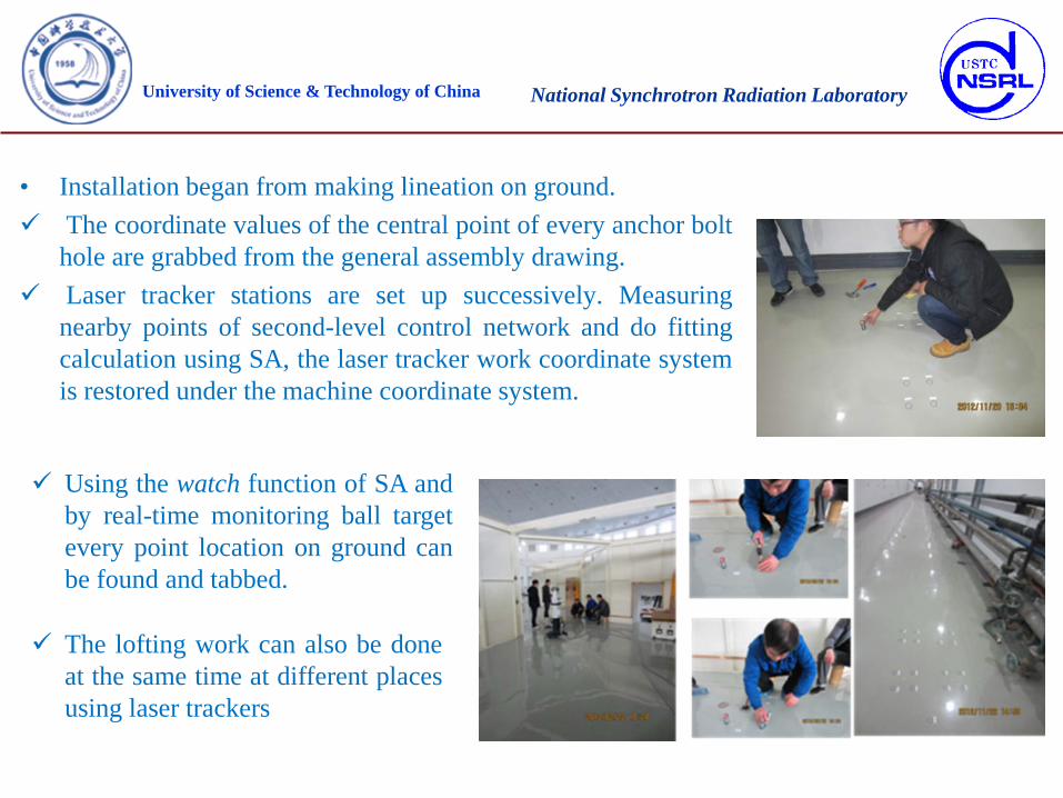
• Installation began from making lineation on ground. The coordinate values of the central point of every anchor bolt
hole are grabbed from the general assembly drawing. Laser tracker stations are set up successively. Measuring
nearby points of second-level control network and do fitting calculation using SA, the laser tracker work coordinate system is restored under the machine coordinate system.
Using the watch function of SA and by real-time monitoring ball target every point location on ground can be found and tabbed.
The lofting work can also be done at the same time at different places using laser trackers

National Synchrotron Radiation Laboratory University of Science & Technology of China
After tabbing the locations of holes they are drilled and the foundation bolts are put in them and then supports can be installed,
Adjusted and fixed accurately by monitoring targets placed on the holes on the supports’ plates for alignment which have also coordinate values under the machine system.

National Synchrotron Radiation Laboratory University of Science & Technology of China
After supports are placed, accelerating tubes, different kinds of magnets and other units are housed on corresponding supports
Setting up laser tracker nearing the unit to be installed , and measuring the nearby points of the second-level control network that are distributed spatially.
Using lofting function of SA to real-time monitoring the points on units and adjusting the unit place according to the deviation and deviating direction monitored repeatedly
Then using electronical inclinometer to monitoring and adjusting the gesture of unit, after all the readings are within a reasonable error range, the adjusting screws are screwed up and the unit is installed correctly for the first time

National Synchrotron Radiation Laboratory University of Science & Technology of China

National Synchrotron Radiation Laboratory University of Science & Technology of China
For the four undulators because they are large and laser tracker cannot measure all the points on them in one station two laser trackers are needed to set up stations around at the same time to measure the points. Some vacuum tubes with large volume have
target holes on their flanges’ sides which have designed coordinate values and they can be adjusted according to the values to their places.

National Synchrotron Radiation Laboratory University of Science & Technology of China
• INTRODUCTION • ESTABLISHMENT, MEASUREMENT AND
DATA PROCESSING OF FIRST-LEVEL CONTROL NETWORK
• ESTABLISHMENT, MEASUREMENT AND DATA PROCESSING OF SECOND-LEVEL CONTROL NETWORK
• PRE-ALIGNMENT OF UNITS • ALIGNMENT DURING INSTALLATION • CONCLUSIONS • ACKNOWLEDGEMENT

National Synchrotron Radiation Laboratory University of Science & Technology of China
• The alignment work was completed in September, 2013 and afterwards water and electricity systems and other supporting facilities were installed.
• In November of 2013 the linac started commissioning and beam was gotten very soon.
• In February of 2014 the storage ring run with beam. Thus the alignment work was completed successfully then.

National Synchrotron Radiation Laboratory University of Science & Technology of China
• INTRODUCTION • ESTABLISHMENT, MEASUREMENT AND
DATA PROCESSING OF FIRST-LEVEL CONTROL NETWORK
• ESTABLISHMENT, MEASUREMENT AND DATA PROCESSING OF SECOND-LEVEL CONTROL NETWORK
• PRE-ALIGNMENT OF UNITS • ALIGNMENT DURING INSTALLATION • CONCLUSIONS • ACKNOWLEDGEMENT

National Synchrotron Radiation Laboratory University of Science & Technology of China
In the course of engineering our alignment work obtained tremendous helps from colleagues who are from IHEP and IMP and with them work efficiency was improved and period shortened greatly. Luo Tao and Wang Tong from IHEP, Cai Guozhu, Wang Shaoming, Yuan Jiandong and Chen Wenjun from IMP, participated different periods of alignment work for structuring and measuring the first- and second-level control network and the pre-alignment respectively. I would like to express my most sincere thanks for them all.

National Synchrotron Radiation Laboratory University of Science & Technology of China
Thank you for your attention!