commissioning guide(v200r007 04,umts)
TRANSCRIPT
HUAWEI UMG8900 Universal Media Gateway
V200R007
Commissioning Guide
Issue 04
Date 2009-01-09
Part Number 00347903
Huawei Proprietary and ConfidentialCopyright © Huawei Technologies Co., Ltd.
Huawei Technologies Co., Ltd. provides customers with comprehensive technical support and service. For anyassistance, please contact our local office or company headquarters.
Huawei Technologies Co., Ltd.Address: Huawei Industrial Base
Bantian, LonggangShenzhen 518129People's Republic of China
Website: http://www.huawei.com
Email: [email protected]
Copyright © Huawei Technologies Co., Ltd. 2009. All rights reserved.No part of this document may be reproduced or transmitted in any form or by any means without prior writtenconsent of Huawei Technologies Co., Ltd. Trademarks and Permissions
and other Huawei trademarks are the property of Huawei Technologies Co., Ltd.All other trademarks and trade names mentioned in this document are the property of their respective holders. NoticeThe information in this document is subject to change without notice. Every effort has been made in thepreparation of this document to ensure accuracy of the contents, but the statements, information, andrecommendations in this document do not constitute a warranty of any kind, express or implied.
Huawei Proprietary and ConfidentialCopyright © Huawei Technologies Co., Ltd.

Contents
About This Document.....................................................................................................................1
1 Introduction to System Commissioning................................................................................1-11.1 System Commissioning Procedure..................................................................................................................1-21.2 Steps for System Commissioning...................................................................................................................1-3
2 Preparations for System Commissioning..............................................................................2-12.1 Preparing Technical Documents.....................................................................................................................2-22.2 Checking Construction Conditions.................................................................................................................2-32.3 Checking Configurations and Status of Hardware..........................................................................................2-4
2.3.1 Checking Hardware Configuration........................................................................................................2-42.3.2 Checking Status of Power Distribution Frames.....................................................................................2-52.3.3 Checking Status of Frames and Boards..................................................................................................2-62.3.4 Checking Status of LAN Switches.........................................................................................................2-6
2.4 Checking Software Versions and Running Status...........................................................................................2-72.4.1 Checking LMT Software Versions........................................................................................................2-72.4.2 Checking Host Software.........................................................................................................................2-8
2.5 Checking Communication Between the LMT and the Host...........................................................................2-8
3 Checking Data Configuration..................................................................................................3-13.1 Checking Hardware Data................................................................................................................................3-23.2 Checking Interconnection Data.......................................................................................................................3-3
4 Debugging Local Office ...........................................................................................................4-14.1 Debugging Boards...........................................................................................................................................4-2
4.1.1 Checking DIP Switches..........................................................................................................................4-24.1.2 Checking Board Running States..........................................................................................................4-114.1.3 Checking Software Versions of Boards...............................................................................................4-124.1.4 Debugging Board Switchover..............................................................................................................4-12
4.2 Debugging Clock...........................................................................................................................................4-134.2.1 Checking Clock Cables........................................................................................................................4-144.2.2 Debugging Networking of Single Reference Source...........................................................................4-154.2.3 Debugging Networking of Multiple Reference Source........................................................................4-16
4.3 Debugging System Time...............................................................................................................................4-174.3.1 Checking Time Synchronization Mode................................................................................................4-174.3.2 Checking Time Zone............................................................................................................................4-17
HUAWEI UMG8900 Universal Media GatewayCommissioning Guide Contents
Issue 04 (2009-01-09) Huawei Proprietary and ConfidentialCopyright © Huawei Technologies Co., Ltd.
i
4.3.3 Checking NTP Server...........................................................................................................................4-184.3.4 Checking Settings of Daylight Saving Time........................................................................................4-18
4.4 Debugging Cascading...................................................................................................................................4-184.4.1 SSM-256 Self-Cascading.....................................................................................................................4-194.4.2 SSM-32 Self-Cascading.......................................................................................................................4-204.4.3 SSM-256 and SSM-32 Mixed Cascading (UG01NET and BLU.A Configured)................................4-224.4.4 SSM-256 and SSM-32 Mixed Cascading (UG02NET and BLU.C Configured)................................4-274.4.5 Process of Cascading Switchover........................................................................................................4-334.4.6 Checking Cascading Cable Connection...............................................................................................4-354.4.7 Checking Cascading Configurations and States of Cascading Boards................................................4-354.4.8 Debugging FE Cascading.....................................................................................................................4-364.4.9 Debugging TDM Cascading.................................................................................................................4-374.4.10 Debugging GE Cascading..................................................................................................................4-38
4.5 Debugging Service Resources.......................................................................................................................4-414.5.1 Debugging TC Resources.....................................................................................................................4-424.5.2 Debugging EC Resources.....................................................................................................................4-424.5.3 Debugging MPTY Resources...............................................................................................................4-434.5.4 Debugging IWF Resources..................................................................................................................4-44
5 Debugging Interconnection Between the UMG8900 and the MGC................................ 5-15.1 Debugging Gateway Control Interfaces..........................................................................................................5-35.2 Debugging Gateway Registration Function....................................................................................................5-45.3 Debugging PPU Load Sharing........................................................................................................................5-6
6 Debugging Interconnection Between the UMG8900 and the RNC................................. 6-16.1 Debugging ATM Interfaces............................................................................................................................6-36.2 Debugging SAAL Links..................................................................................................................................6-46.3 Debugging MTP3B Links...............................................................................................................................6-46.4 Debugging Q.AAL2 Links..............................................................................................................................6-5
7 Debugging Interconnection Between the UMG8900 and the BSC/MSC/PSTN Switch...........................................................................................................................................................7-1
7.1 Making E1/T1 Self-Loopback Tests...............................................................................................................7-27.2 Debugging E1/T1 Links..................................................................................................................................7-27.3 Debugging E3/T3 Ports...................................................................................................................................7-47.4 Debugging SDH Interfaces.............................................................................................................................7-57.5 Debugging SDH Interface Protection.............................................................................................................7-6
8 Debugging Interconnection Between the UMG8900 and Other MGWs/BSCs/RNCs...........................................................................................................................................................8-1
8.1 Debugging IP Interfaces..................................................................................................................................8-28.1.1 Debugging Ethernet Interfaces ..............................................................................................................8-28.1.2 Debugging IPoE1 Interfaces..................................................................................................................8-38.1.3 Debugging Network Layer.....................................................................................................................8-4
8.2 Debugging IP Bearer.......................................................................................................................................8-5
ContentsHUAWEI UMG8900 Universal Media Gateway
Commissioning Guide
ii Huawei Proprietary and ConfidentialCopyright © Huawei Technologies Co., Ltd.
Issue 04 (2009-01-09)

8.3 Debugging IP Interface Protection..................................................................................................................8-68.4 Debugging Route Backup...............................................................................................................................8-7
9 Debugging Signaling Transfer................................................................................................9-19.1 Debugging MTP2-M2UA Signaling Links.....................................................................................................9-29.2 Debugging MTP3-M3UA Signaling Links.....................................................................................................9-49.3 Debugging MTP3B-M3UA Signaling Links..................................................................................................9-69.4 Debugging Q.921-IUA Signaling Links.........................................................................................................9-89.5 Debugging R2 Signaling Transfer.................................................................................................................9-10
10 Debugging Services...............................................................................................................10-110.1 Debugging Voice Services..........................................................................................................................10-210.2 Debugging Supplementary Services...........................................................................................................10-310.3 Debugging MPTY Services........................................................................................................................10-410.4 Debugging Data Services............................................................................................................................10-4
A System Commissioning Records..........................................................................................A-1A.1 Preparations for System Commissioning......................................................................................................A-2A.2 Data Configuration........................................................................................................................................A-3A.3 Debugging of Local Office Hardware...........................................................................................................A-4A.4 Interconnection Debugging...........................................................................................................................A-5A.5 Service Debugging........................................................................................................................................A-7
B Settings of DIP Switches of Frames and Boards.................................................................B-1B.1 Settings of DIP Switches of Frames..............................................................................................................B-2B.2 Board DIP Switches and Jumpers of all SSM Frames...................................................................................B-2
B.2.1 DIP Switches and Jumpers of the ME32..............................................................................................B-2B.2.2 DIP Switches on the MEAC.................................................................................................................B-5B.2.3 DIP Switches and Jumpers of the MESU.............................................................................................B-6B.2.4 Jumpers on the MMPU.........................................................................................................................B-7B.2.5 Jumpers on the MOMU........................................................................................................................B-8B.2.6 DIP Switches and Jumpers of the MT32..............................................................................................B-8B.2.7 DIP Switches and Jumpers of the MTAC...........................................................................................B-10B.2.8 DIP Switches and Jumpers of the MTSU...........................................................................................B-11
Index.................................................................................................................................................i-1
HUAWEI UMG8900 Universal Media GatewayCommissioning Guide Contents
Issue 04 (2009-01-09) Huawei Proprietary and ConfidentialCopyright © Huawei Technologies Co., Ltd.
iii


Figures
Figure 1-1 System Commissioning Procedure.....................................................................................................1-2Figure 2-1 LMT Connecting to the Host..............................................................................................................2-9Figure 4-1 Rear view of the SSM frame..............................................................................................................4-2Figure 4-2 DIP switch on the transfer board........................................................................................................4-3Figure 4-3 Board color.......................................................................................................................................4-11Figure 4-4 SSM-256 nine-frame cascading .......................................................................................................4-19Figure 4-5 Three-frame self-cascading of SSM-32 frames................................................................................4-20Figure 4-6 Three-frame self-cascading of SSM-32 frames................................................................................4-22Figure 4-7 Mixed cascading of one SSM-256 frame and four SSM-32 frames through the TNB....................4-24Figure 4-8 Mixed cascading of one SSM-256 frame and two SSM-32 frames through the TNB.....................4-25Figure 4-9 Mixed cascading of one SSM-256 frame and four SSM-32 frames through the BLU....................4-26Figure 4-10 Mixed cascading of one SSM-256 frame and four SSM-32 frames through the TNB (without GEcascading)............................................................................................................................................................4-28Figure 4-11 Mixed cascading of one SSM-256 frame and two SSM-32 frames through the TNB (without GEcascading)............................................................................................................................................................4-29Figure 4-12 Mixed cascading of one SSM-256 frame and two SSM-32 frames through the TNB (with GEcascading)............................................................................................................................................................4-30Figure 4-13 Mixed cascading of one SSM-256 frame and four SSM-32 frames through the BLU (without GEcascading) ...........................................................................................................................................................4-31Figure 4-14 Mixed cascading of one SSM-256 frame and two SSM-32 frames through the BLU (with GEcascading)............................................................................................................................................................4-32Figure 5-1 Protocol stack of the H.248 interface based on IP bearer...................................................................5-1Figure 6-1 Structure of the protocol stack based on the ATM bearer..................................................................6-1Figure 9-1 Signaling adaptation and transfer in the MTP2-M2UA mode............................................................9-2Figure 9-2 Signaling adaptation and transfer in the MTP3-M3UA mode............................................................9-4Figure 9-3 Signaling adaptation and transfer in MTP3B-M3UA mode...............................................................9-6Figure 9-4 Signaling adaptation and transfer in Q.921-IUA mode......................................................................9-9
HUAWEI UMG8900 Universal Media GatewayCommissioning Guide Figures
Issue 04 (2009-01-09) Huawei Proprietary and ConfidentialCopyright © Huawei Technologies Co., Ltd.
v

Tables
Table 2-1 Reference documents and their usage descriptions..............................................................................2-2Table 2-2 Technical documents used in system commissioning..........................................................................2-2Table 4-1 Mapping between frame IDs and the DIP switch settings of the SSM-256 frame..............................4-3Table 4-2 DIP switches of the UG01ME32..........................................................................................................4-4Table 4-3 Setting the DIP switches of the UG01ME32 (75-ohm E1 coaxial cable)............................................4-5Table 4-4 Setting the DIP switches of the UG01ME32 (120-ohm E1 twisted pair)............................................4-5Table 4-5 DIP switches of the UG02ME32..........................................................................................................4-5Table 4-6 Setting the DIP switches of the UG02ME32 (75-ohm E1 coaxial cable)............................................4-6Table 4-7 Setting the DIP switches of the UG02ME32 (120-ohm E1 twisted pair)............................................4-6Table 4-8 DIP switches of the MESU..................................................................................................................4-7Table 4-9 Setting the DIP switches of the MESU (75-ohm E1 coaxial cable).....................................................4-7Table 4-10 Setting the DIP switches of the MESU (120-ohm E1 twisted pair)...................................................4-7Table 4-11 DIP switches of the UG01MT32........................................................................................................4-8Table 4-12 Setting the DIP switches of the UG01MT32 (100-ohm T1 cable)....................................................4-9Table 4-13 DIP switches of the UG02MT32........................................................................................................4-9Table 4-14 Setting the DIP switches of the UG02MT32 (100-ohm T1 cable)..................................................4-10Table 4-15 DIP switches of the MTSU..............................................................................................................4-10Table 4-16 Setting the DIP switches of the MTSU (100-ohm T1 cable)...........................................................4-11Table 4-17 Meanings of the colors indicating the board states..........................................................................4-12Table 4-18 Influence of the cascading switchover.............................................................................................4-34Table 5-1 H.248 link information.........................................................................................................................5-5Table 5-2 H.248 parameter information...............................................................................................................5-5Table A-1 Preparations for system commissioning.............................................................................................A-2Table A-2 Data configurations............................................................................................................................A-3Table A-3 Debugging of local office hardware...................................................................................................A-4Table A-4 Interconnection debugging.................................................................................................................A-5Table A-5 Service debugging..............................................................................................................................A-7Table B-1 DIP switches of the UG01ME32........................................................................................................B-2Table B-2 Setting DIP switches of the UG01ME32 (75-ohm E1 coaxial cable)................................................B-3Table B-3 Setting DIP switches of the UG01ME32 (120-ohm E1 twisted pair).................................................B-3Table B-4 DIP switches of the UG02ME32........................................................................................................B-4Table B-5 Setting DIP switches of the UG02ME32 (75-ohm E1 coaxial cable)................................................B-4Table B-6 Setting DIP switches of the UG02ME32 (120-ohm E1 twisted pair).................................................B-5
HUAWEI UMG8900 Universal Media GatewayCommissioning Guide Tables
Issue 04 (2009-01-09) Huawei Proprietary and ConfidentialCopyright © Huawei Technologies Co., Ltd.
vii
Table B-7 DIP switches of the MEAC................................................................................................................B-5Table B-8 Setting DIP switches of the MEAC (75-ohm E1 coaxial cable).........................................................B-6Table B-9 Setting DIP switches of the MEAC (120-ohm E1 twisted pair).........................................................B-6Table B-10 DIP switches of the MESU...............................................................................................................B-6Table B-11 Setting DIP switches of the MESU (75-ohm E1 coaxial cable).......................................................B-7Table B-12 Setting DIP switches of the MESU (120-ohm E1 twisted pair).......................................................B-7Table B-13 Jumper description of the MMPU....................................................................................................B-8Table B-14 Jumper description of the MOMU....................................................................................................B-8Table B-15 DIP switches of the UG01MT32......................................................................................................B-8Table B-16 Setting DIP switches of the UG01MT32 (100-ohm T1 cable).........................................................B-9Table B-17 DIP switches of the UG02MT32......................................................................................................B-9Table B-18 Setting DIP switches of the UG02MT32 (100-ohm T1 cable).......................................................B-10Table B-19 DIP switches of the MTAC............................................................................................................B-10Table B-20 Setting DIP switches of the MTAC (100-ohm T1 cable)...............................................................B-11Table B-21 DIP switches of the MTSU.............................................................................................................B-11Table B-22 Setting DIP switches of the MTSU (100-ohm T1 cable)................................................................B-12
TablesHUAWEI UMG8900 Universal Media Gateway
Commissioning Guide
viii Huawei Proprietary and ConfidentialCopyright © Huawei Technologies Co., Ltd.
Issue 04 (2009-01-09)

About This Document
PurposeThis document introduces the system commissioning of the UMG8900.
Related VersionsThe following table lists the product versions related to this document.
Product Name Version
HUAWEI UMG8900 V200R007
Intended AudienceThe intended audiences of this document are:
l Field technician
l Network administrator
l System engineer
l Commissioning engineer
l Operation and maintenance engineer
Update HistoryUpdates between document versions are cumulative. Therefore, the latest document versioncontains all updates made to previous versions.
Updates in Issue 04 (2009-01-09)
Third commercial release. The updated contents are as follows.
The description of legend colors is modified.
Updates in Issue 03 (2008-04-11)
Second commercial release
Updates in Issue 02 (2007-11-28)
Initial commercial release
Updates in Issue 01 (2007-07-26)
HUAWEI UMG8900 Universal Media GatewayCommissioning Guide About This Document
Issue 04 (2009-01-09) Huawei Proprietary and ConfidentialCopyright © Huawei Technologies Co., Ltd.
1
Initial field trial release
OrganizationThis document introduces the system commissioning of the UMG8900.
1 Introduction to System Commissioning
This describes the procedure and steps for debugging the UMG8900.
2 Preparations for System Commissioning
This describes the preparations for system commissioning, including materials, constructionconditions, hardware, software, and device status check.
3 Checking Data Configuration
This describes how to check hardware data and interconnection data.
4 Debugging Local Office
This describes how to debug boards, clock, system time, cascading, and service resources.
5 Debugging Interconnection Between the UMG8900 and the MGC
This describes how to debug the H.248 protocol.
6 Debugging Interconnection Between the UMG8900 and the RNC
This describes how to debug the Iu interface, including how to debug the asynchronous transfermode (ATM) interface, Signaling ATM Adaptation Layer (SAAL) link, Message Transfer Part(broadband) (MTP3B) link, and Q.AAL2 link.
7 Debugging Interconnection Between the UMG8900 and the BSC/MSC/PSTN Switch
This describes how to debug the E1/T1, E3/T3, and synchronous digital hierarchy (SDH)interface.
8 Debugging Interconnection Between the UMG8900 and Other MGWs/BSCs/RNCs
This describes how to debug the IP interfaces and IP bearer.
9 Debugging Signaling Transfer
This describes how to debug the SIGTRAN protocol and channel associated signaling (CAS).
10 Debugging Services
This describes how to debug voice services, supplementary services, MPTY services, and dataservices.
A System Commissioning Records
This provides the system commissioning record.
B Settings of DIP Switches of Frames and Boards
This describes how to set the dial in-line package (DIP) switches of frames and boards.
Conventions1. Symbol Conventions
About This DocumentHUAWEI UMG8900 Universal Media Gateway
Commissioning Guide
2 Huawei Proprietary and ConfidentialCopyright © Huawei Technologies Co., Ltd.
Issue 04 (2009-01-09)

The following symbols may be found in this document. They are defined as follows
Symbol Description
DANGERIndicates a hazard with a high level of risk that, if not avoided,will result in death or serious injury.
WARNINGIndicates a hazard with a medium or low level of risk which, ifnot avoided, could result in minor or moderate injury.
CAUTIONIndicates a potentially hazardous situation that, if not avoided,could cause equipment damage, data loss, and performancedegradation, or unexpected results.
TIP Indicates a tip that may help you solve a problem or save yourtime.
NOTE Provides additional information to emphasize or supplementimportant points of the main text.
2. General Conventions
Convention Description
Times New Roman Normal paragraphs are in Times New Roman.
Boldface Names of files,directories,folders,and users are in boldface. Forexample,log in as user root .
Italic Book titles are in italics.
Courier New Terminal display is in Courier New.
3. Command Conventions
Convention Description
Boldface The keywords of a command line are in boldface.
Italic Command arguments are in italic.
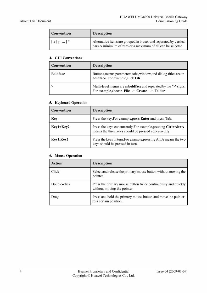
[ ] Items (keywords or arguments) in square brackets [ ] are optional.
{x | y | ...} Alternative items are grouped in braces and separated by verticalbars.One is selected.
[ x | y | ... ] Optional alternative items are grouped in square brackets andseparated by vertical bars.One or none is selected.
{ x | y | ... } * Alternative items are grouped in braces and separated by verticalbars.A minimum of one or a maximum of all can be selected.
HUAWEI UMG8900 Universal Media GatewayCommissioning Guide About This Document
Issue 04 (2009-01-09) Huawei Proprietary and ConfidentialCopyright © Huawei Technologies Co., Ltd.
3
Convention Description
[ x | y | ... ] * Alternative items are grouped in braces and separated by verticalbars.A minimum of zero or a maximum of all can be selected.
4. GUI Conventions
Convention Description
Boldface Buttons,menus,parameters,tabs,window,and dialog titles are inboldface. For example,click OK.
> Multi-level menus are in boldface and separated by the ">" signs.For example,choose File > Create > Folder .
5. Keyboard Operation
Convention Description
Key Press the key.For example,press Enter and press Tab.
Key1+Key2 Press the keys concurrently.For example,pressing Ctrl+Alt+Ameans the three keys should be pressed concurrently.
Key1,Key2 Press the keys in turn.For example,pressing Alt,A means the twokeys should be pressed in turn.
6. Mouse Operation
Action Description
Click Select and release the primary mouse button without moving thepointer.
Double-click Press the primary mouse button twice continuously and quicklywithout moving the pointer.
Drag Press and hold the primary mouse button and move the pointerto a certain position.
About This DocumentHUAWEI UMG8900 Universal Media Gateway
Commissioning Guide
4 Huawei Proprietary and ConfidentialCopyright © Huawei Technologies Co., Ltd.
Issue 04 (2009-01-09)
1 Introduction to System Commissioning
About This Chapter
This describes the procedure and steps for debugging the UMG8900.
1.1 System Commissioning ProcedureThis describes the procedure for debugging the UMG8900.
1.2 Steps for System CommissioningThis describes the steps for system commissioning.
HUAWEI UMG8900 Universal Media GatewayCommissioning Guide 1 Introduction to System Commissioning
Issue 04 (2009-01-09) Huawei Proprietary and ConfidentialCopyright © Huawei Technologies Co., Ltd.
1-1
1.1 System Commissioning ProcedureThis describes the procedure for debugging the UMG8900.
Purpose
System commissioning refers to a series of debugging and verification on the system after thehardware and software are installed. The system can run as designed through commissioning ina stable, reliable, and secure way.
Debugging Procedure
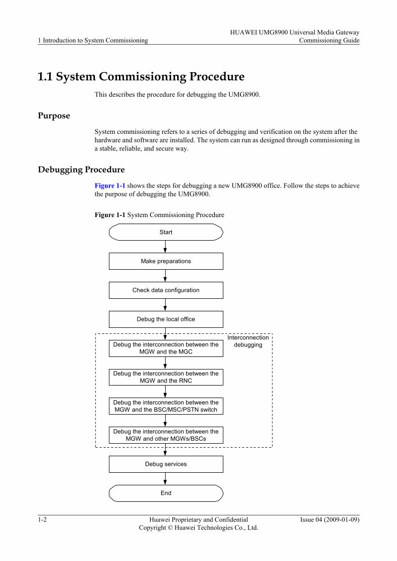
Figure 1-1 shows the steps for debugging a new UMG8900 office. Follow the steps to achievethe purpose of debugging the UMG8900.
Figure 1-1 System Commissioning Procedure
Make preparations
Start
Check data configuration
Debug the local office
Debug the interconnection between theMGW and the MGC
Debug the interconnection between theMGW and the BSC/MSC/PSTN switch
Debug the interconnection between theMGW and other MGWs/BSCs
Debug the interconnection between theMGW and the RNC
Interconnectiondebugging
End
Debug services
1 Introduction to System CommissioningHUAWEI UMG8900 Universal Media Gateway
Commissioning Guide
1-2 Huawei Proprietary and ConfidentialCopyright © Huawei Technologies Co., Ltd.
Issue 04 (2009-01-09)

1.2 Steps for System CommissioningThis describes the steps for system commissioning.
1. Make preparations for system commissioning.Prepare the documents for system commissioning and check the hardware and software,including hardware configuration and status (for example, frames, boards, and LANSwitches), software version and running status, and network communication status.
2. Check data configurations.Collect and plan data, check and modify data scripts (including hardware data andinterconnection data), and verify their correctness.
3. Debug local offices.Debug local hardware data, including dial in-line package (DIP) switch settings, boardrunning status, software versions, board switchover, clock cables, single reference sourcenetworking, multiple reference source networking, system time, cascading functions, andservice resources.
4. Debug interconnection data.Debug the data for interconnection between the UMG8900 and the media gatewaycontroller (MGC), radio network controller (RNC), base station controller (BSC), mobileswitching center (MSC), public switched telephone network (PSTN) switch, and mediagateway (MGW) in the core network (CN). The interconnected devices vary with thenetworking.
5. Debug signaling transfer.Debug the following: MTP2-M2UA signaling links, MTP3-M3UA signaling links, R2signaling transfer, and MTP3B-M3UA signaling links.
6. Debug services.Debug the following: voice services, supplementary services, MPTY services, and dataservices.
HUAWEI UMG8900 Universal Media GatewayCommissioning Guide 1 Introduction to System Commissioning
Issue 04 (2009-01-09) Huawei Proprietary and ConfidentialCopyright © Huawei Technologies Co., Ltd.
1-3


2 Preparations for System Commissioning
About This Chapter
This describes the preparations for system commissioning, including materials, constructionconditions, hardware, software, and device status check.
2.1 Preparing Technical DocumentsThis describes the reference documents to prepare and the technical documents to deliver.
2.2 Checking Construction ConditionsThis describes the requirements of hardware and software.
2.3 Checking Configurations and Status of HardwareThis describes the configurations and status of hardware, including the service switching module(SSM), power distribution frames (PDF), local maintenance terminal (LMT) client, and LANSwitches.
2.4 Checking Software Versions and Running StatusThis describes how to check software versions of the local maintenance terminal (LMT) andhost.
2.5 Checking Communication Between the LMT and the HostThis describes how to check the communication between the local maintenance terminal(LMT) and the host.
HUAWEI UMG8900 Universal Media GatewayCommissioning Guide 2 Preparations for System Commissioning
Issue 04 (2009-01-09) Huawei Proprietary and ConfidentialCopyright © Huawei Technologies Co., Ltd.
2-1
2.1 Preparing Technical DocumentsThis describes the reference documents to prepare and the technical documents to deliver.
Procedure
Step 1 Check reference documents.
This document describes the solution clues for system commissioning rather than detailedoperation steps. For the detailed operation steps for specific debugging, see related help andmanuals. For example, in terms of interface trace, this document only describes the requirementof creating interface trace tasks, but does not cover the steps for creating interface trace tasks.For details about the steps, see the local maintenance terminal (LMT) online help or HUAWEIUMG8900 Universal Media Gateway Operation Guide Trace Management.
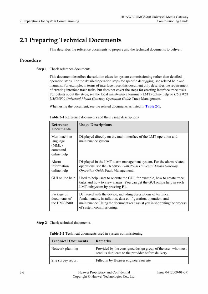
When using the document, see the related documents as listed in Table 2-1.
Table 2-1 Reference documents and their usage descriptions
ReferenceDocuments
Usage Descriptions
Man-machinelanguage(MML)commandonline help
Displayed directly on the main interface of the LMT operation andmaintenance system
Alarminformationonline help
Displayed in the LMT alarm management system. For the alarm relatedoperations, see the HUAWEI UMG8900 Universal Media GatewayOperation Guide Fault Management.
GUI online help Used to help users to operate the GUI, for example, how to create tracetasks and how to view alarms. You can get the GUI online help in eachLMT subsystem by pressing F1.
Package ofdocuments ofthe UMG8900
Delivered with the device, including descriptions of technicalfundamentals, installation, data configuration, operation, andmaintenance. Using the documents can assist you in shortening the processof system commissioning.
Step 2 Check technical documents.
Table 2-2 Technical documents used in system commissioning
Technical Documents Remarks
Network planning Provided by the consigned design group of the user, who mustsend its duplicate to the provider before delivery
Site survey report Filled in by Huawei engineers on site
2 Preparations for System CommissioningHUAWEI UMG8900 Universal Media Gateway
Commissioning Guide
2-2 Huawei Proprietary and ConfidentialCopyright © Huawei Technologies Co., Ltd.
Issue 04 (2009-01-09)

Technical Documents Remarks
Engineering documents Prescribed by Huawei Engineering Department according tothe configuration and networking conditions of the user's officeand delivered to the site along with the device
Package of equipmentdocuments
Delivered with the device by Huawei Technologies Co., Ltd.(hereinafter referred to as Huawei), including installationdocuments, operation documents, hardware descriptiondocuments, and maintenance documents
Software and data scripts Provided by Huawei
Other engineeringdocuments
Including contracts, device configuration tables, and deliverylists
----End
PostrequisiteWhen technical documents are prepared, check construction conditions.
2.2 Checking Construction ConditionsThis describes the requirements of hardware and software.
PurposeCheck whether the hardware and software of the UMG8900 are installed and normally poweredon.
Procedure
Step 1 Check whether the hardware is installed.
Step 2 Check whether the hardware installation is checked.
Step 3 Check whether the UMG8900 is powered on.
Step 4 Check whether the software of the host and local maintenance terminal (LMT) client is installed.
Step 5 Check whether the software is installed.
----End
PostrequisiteAfter construction condition check is complete, check the configuration and status of hardware.
HUAWEI UMG8900 Universal Media GatewayCommissioning Guide 2 Preparations for System Commissioning
Issue 04 (2009-01-09) Huawei Proprietary and ConfidentialCopyright © Huawei Technologies Co., Ltd.
2-3

2.3 Checking Configurations and Status of HardwareThis describes the configurations and status of hardware, including the service switching module(SSM), power distribution frames (PDF), local maintenance terminal (LMT) client, and LANSwitches.
PrerequisiteBefore debugging the UMG8900, ensure that the hardware installation is checked, theUMG8900 is powered on, and the software is installed.
Context
By observing the indicators on the device, check whether the status of the UMG8900 is normal.This ensures that the subsequent debugging can be performed smoothly.
1. 2.3.1 Checking Hardware ConfigurationThis describes how to check cabinets, frames, boards, local maintenance terminal (LMT),and cables.
2. 2.3.2 Checking Status of Power Distribution FramesThis describes how to check the output switches, indicators, cables, and alarms.
3. 2.3.3 Checking Status of Frames and BoardsThis describes how to check the status of fans and boards.
4. 2.3.4 Checking Status of LAN SwitchesThis describes how to check the status of LAN Switches.
2.3.1 Checking Hardware ConfigurationThis describes how to check cabinets, frames, boards, local maintenance terminal (LMT), andcables.
ContextNOTE
If the hardware configurations are inconsistent with those in Engineering documents, contact HuaweiTechnical Support at once.
Procedurel Check cabinets.
Check whether the number of cabinets is consistent with that in Engineering documents.l Check frames.
Check whether the number of frames is consistent with that in Engineering documents.l Check boards.
Check whether the number of boards is consistent with that in Engineering documents andwhether board positions are correct.
l Check the PC client and auxiliary devices.
2 Preparations for System CommissioningHUAWEI UMG8900 Universal Media Gateway
Commissioning Guide
2-4 Huawei Proprietary and ConfidentialCopyright © Huawei Technologies Co., Ltd.
Issue 04 (2009-01-09)

Check whether the PC where the LMT client is installed and the alarm box are consistentwith those in the delivery list.
l Check cable suites.
Check whether the cable suites, including environmental monitoring cables, alarm boxcables, and cascading cables, are complete.
l Check dial in-line package (DIP) switches.
Check whether the 8-bit DIP switches on the transit card at the rear underside of each frameconsistent with the frame No. planned.
NOTE
For details about DIP switches, see the HUAWEI UMG8900 Universal Media Gateway HardwareDescription Frames.
----End
PostrequisiteAfter checking hardware configurations, check the status of power distribution frames.
2.3.2 Checking Status of Power Distribution FramesThis describes how to check the output switches, indicators, cables, and alarms.
Procedure
Step 1 Check power output switches.
Check whether all output switches of NEG power are on.
NOTE
For power distribution relationship between power output switches and all components in cabinets, see theHUAWEI UMG8900 Universal Media Gateway Hardware Description Frames.
Step 2 Check indicators.
Check whether the green RUN indicators on the front panel flash once every second and the redALM indicators are off.
When RUN indicators are off, it indicates no power input or power distribution frame failure.When ALM indicators are on, it indicates that the power distribution frames are faulty.
Step 3 Check alarm prompt tones.
Check whether the power alarm buzzer does not sound when the stop-alarm-sound switch onthe front panel is on.
Check whether the power alarm buzzer does not sound for the power distribution frame failurewhen the stop-alarm-sound switch is off.
----End
PostrequisiteAfter checking the status of power distribution frames, check the status of frames and boards.
HUAWEI UMG8900 Universal Media GatewayCommissioning Guide 2 Preparations for System Commissioning
Issue 04 (2009-01-09) Huawei Proprietary and ConfidentialCopyright © Huawei Technologies Co., Ltd.
2-5
2.3.3 Checking Status of Frames and BoardsThis describes how to check the status of fans and boards.
ContextNOTE
For details about indicators on each board, see the HUAWEI UMG8900 Universal Media GatewayHardware DescriptionEquipment Management and Maintenance Units.
Procedure
Step 1 Check fans.
One fan box is configured for each frame of the media gateway (MGW), and it is at the bottomof frames.
Check whether fan indicators are green and flash one second on and one second off. If yes, itindicates that the fan runs normally.
Step 2 Check RUN indicators.
Check whether RUN indicators on boards are green and flash one second on and one second off.
State descriptions of RUN indicators:
l If RUN indicators are always on, it indicates that input power exists and boards fail.
l If RUN indicators are always off, it indicates that no input power exists or boards fail.
l If RUN indicators flash every other second, it indicates that the boards run normally.
l If RUN indicators flash four times a second, it indicates that boards are not loaded or boardsare disabled. Distinguish whether boards are not loaded or disabled through the background.If the boards are loaded, the loading process prompt exists.
l If RUN indicators slowly flash two seconds on and two seconds off, it indicates that theMBus module and boards fail in communication or the MBus module runs offline.
Step 3 Check ALM indicators.
Check whether red ALM indicators on boards are off.
State descriptions of ALM indicators:
l If ALM indicators are on or quickly flash, it indicates that a failure exists.
l If ALM indicators are always off, it indicates that no failure exists.
----End
PostrequisiteAfter checking the status of frames and boards, check the status of LAN Switches.
2.3.4 Checking Status of LAN SwitchesThis describes how to check the status of LAN Switches.
2 Preparations for System CommissioningHUAWEI UMG8900 Universal Media Gateway
Commissioning Guide
2-6 Huawei Proprietary and ConfidentialCopyright © Huawei Technologies Co., Ltd.
Issue 04 (2009-01-09)
Procedure
Step 1 Check LAN Switches.
Check whether POWER indicators on LAN Switch 0 and LAN Switch 1 are on.
If POWER indicators are off, it indicates that the power supply of LAN Switches is abnormal.
Step 2 Check indicators on network interfaces of LAN Switches.
Check whether LINK indicators on all network ports with network cables inserted are on.
If LINK indicators are off, check whether the other end of network cables is well inserted andwhether the network cables are in good quality.
Step 3 Check VLAN configurations.
Connect serial port cables to LAN Switches, and then check whether the displayed configurationresults by using the display command comply with the network planning.
----End
PostrequisiteAfter checking configurations and status of hardware, check software versions and their runningstatus.
2.4 Checking Software Versions and Running StatusThis describes how to check software versions of the local maintenance terminal (LMT) andhost.
PrerequisiteBefore checking software versions and running status, ensure that the host software and LMTclient software are installed and software installation is checked.
ContextCheck the software versions and running status of the host and LMT client. This ensures thatthe subsequent debugging can be performed smoothly.
1. 2.4.1 Checking LMT Software VersionsThis describes how to check LMT software versions.
2. 2.4.2 Checking Host SoftwareThis describes how to check host software versions.
2.4.1 Checking LMT Software VersionsThis describes how to check LMT software versions.
ProcedureOn the local maintenance terminal (LMT), start local maintenance terminal. Choose Help >About to check whether the software version number is consistent with that of the host softwareand whether it meets the deployment requirements.
HUAWEI UMG8900 Universal Media GatewayCommissioning Guide 2 Preparations for System Commissioning
Issue 04 (2009-01-09) Huawei Proprietary and ConfidentialCopyright © Huawei Technologies Co., Ltd.
2-7

If any mismatch exists, contact Huawei Technical Support at once or reinstall the LMT softwareif necessary.
----End
PostrequisiteAfter checking LMT software versions, check host software.
2.4.2 Checking Host SoftwareThis describes how to check host software versions.
ProcedureRun the local maintenance terminal (LMT) and log in to the host. Run CHK VERSION to checkwhether the running host version meets the deployment requirements. If any mismatch exists,contact Huawei Technical Support or upgrade host software versions if necessary.
----End
PostrequisiteAfter checking host software, check the communication between the LMT and the host.
2.5 Checking Communication Between the LMT and theHost
This describes how to check the communication between the local maintenance terminal(LMT) and the host.
PurposeThe UMG8900 operation and maintenance system works in client/server mode. The backadministration module (BAM) is used as the server and the LMT works as the client. The BAMis located on the OMU of the UMG8900. The LMT and the BAM communicate throughTransmission Control Protocol/ Internet Protocol (TCP/IP), and the maintenance staff canoperate and maintain the UMG8900 through the LMT.
LMT connecting to the hostFigure 2-1 shows the connection between the LMT and the host.
2 Preparations for System CommissioningHUAWEI UMG8900 Universal Media Gateway
Commissioning Guide
2-8 Huawei Proprietary and ConfidentialCopyright © Huawei Technologies Co., Ltd.
Issue 04 (2009-01-09)
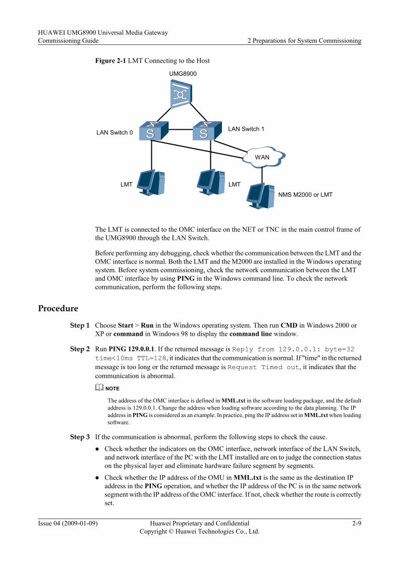
Figure 2-1 LMT Connecting to the Host
LAN Switch 0 LAN Switch 1
LMT
WAN
LMT
UMG8900
NMS M2000 or LMT
The LMT is connected to the OMC interface on the NET or TNC in the main control frame ofthe UMG8900 through the LAN Switch.
Before performing any debugging, check whether the communication between the LMT and theOMC interface is normal. Both the LMT and the M2000 are installed in the Windows operatingsystem. Before system commissioning, check the network communication between the LMTand OMC interface by using PING in the Windows command line. To check the networkcommunication, perform the following steps.
Procedure
Step 1 Choose Start > Run in the Windows operating system. Then run CMD in Windows 2000 orXP or command in Windows 98 to display the command line window.
Step 2 Run PING 129.0.0.1. If the returned message is Reply from 129.0.0.1: byte=32time<10ms TTL=128, it indicates that the communication is normal. If "time" in the returnedmessage is too long or the returned message is Request Timed out, it indicates that thecommunication is abnormal.
NOTE
The address of the OMC interface is defined in MML.txt in the software loading package, and the defaultaddress is 129.0.0.1. Change the address when loading software according to the data planning. The IPaddress in PING is considered as an example. In practice, ping the IP address set in MML.txt when loadingsoftware.
Step 3 If the communication is abnormal, perform the following steps to check the cause.
l Check whether the indicators on the OMC interface, network interface of the LAN Switch,and network interface of the PC with the LMT installed are on to judge the connection statuson the physical layer and eliminate hardware failure segment by segments.
l Check whether the IP address of the OMU in MML.txt is the same as the destination IPaddress in the PING operation, and whether the IP address of the PC is in the same networksegment with the IP address of the OMC interface. If not, check whether the route is correctlyset.
HUAWEI UMG8900 Universal Media GatewayCommissioning Guide 2 Preparations for System Commissioning
Issue 04 (2009-01-09) Huawei Proprietary and ConfidentialCopyright © Huawei Technologies Co., Ltd.
2-9
l If the LMT and the OMC interface are connected through a WAN, a firewall may beconfigured on the communication path. The mismatch of access rules may disable theLMT to ping the OMC interface.
----End
2 Preparations for System CommissioningHUAWEI UMG8900 Universal Media Gateway
Commissioning Guide
2-10 Huawei Proprietary and ConfidentialCopyright © Huawei Technologies Co., Ltd.
Issue 04 (2009-01-09)
3 Checking Data Configuration
About This Chapter
This describes how to check hardware data and interconnection data.
1. 3.1 Checking Hardware DataThis describes how to check hardware data such as cabinets, frames, boards, clock, systemtime, and cascading.
2. 3.2 Checking Interconnection DataThis describes how to check H.248 interconnection data, time division multiplexing(TDM)/Internet Protocol (IP)/asynchronous transfer mode (ATM) bearer data, connectionto the shared interworking function (SIWF), and signaling transfer data.
HUAWEI UMG8900 Universal Media GatewayCommissioning Guide 3 Checking Data Configuration
Issue 04 (2009-01-09) Huawei Proprietary and ConfidentialCopyright © Huawei Technologies Co., Ltd.
3-1
3.1 Checking Hardware DataThis describes how to check hardware data such as cabinets, frames, boards, clock, system time,and cascading.
Procedure
Step 1 Check cabinets and frames.
Check whether cabinets and frames are uniformly numbered.
Step 2 Check boards.
Check whether boards of the same type are uniformly numbered and whether configuration datais easy to read.
Check whether slot positions comply with specifications and whether redundant boards areremoved.
Check whether 1+1 backup boards are configured in paired slots. Master boards are alwaysinserted in even slots, and slave boards are configured in odd slots.
Step 3 Check the clock.
Check whether clock reference sources are configured based on physical cable connection andwhether the work mode of the clock is set to auto when multiple clock reference sources areconfigured.
Check whether the configured clock grade is consistent with the actual grade of clock referencesources. If the grade of clock reference sources is stratum 3 and the configured clock grade isstratum 2, the UMG8900 detects that clock reference sources do not meet the requirement ofthe clock precision and reports the alarm of ALM_2203 Frequency difference of the referenceexceeds scope.
Check whether the priority level of clock reference sources is consistent with that in the actualapplication. If the external BITS clock is connected, the external clock source is of the highestpriority level, and the priority levels rank as follows:GPSPRI=FOURTH,LINE1PRI=SECOND,LINE2PRI=THIRD,EXTPRI=FIRST; If noexternal BITS clock is connected, the line clock is of the highest priority level, and the prioritylevels rank as follows:GPSPRI=FOURTH,LINE1PRI=FIRST,LINE2PRI=SECOND,EXTPRI=THIRD
Step 4 Check the system time.
Check whether the configured time is consistent with the local standard time.
Step 5 Check cascading.
Check whether the cascading board No. is consistent with that of the BLU to which the cascadingboard is connected when adding cascading service frames by using ADD FRM.
----End
PostrequisiteAfter checking hardware data, check interconnection data.
3 Checking Data ConfigurationHUAWEI UMG8900 Universal Media Gateway
Commissioning Guide
3-2 Huawei Proprietary and ConfidentialCopyright © Huawei Technologies Co., Ltd.
Issue 04 (2009-01-09)
3.2 Checking Interconnection DataThis describes how to check H.248 interconnection data, time division multiplexing (TDM)/Internet Protocol (IP)/asynchronous transfer mode (ATM) bearer data, connection to the sharedinterworking function (SIWF), and signaling transfer data.
Procedure
Step 1 Check the connection to the media gateway controller (MGC).l Configure TDM/IP resources for the virtual media gateway (VMGW) as required by the
planning; otherwise, the VMGW cannot be used for bearing services. Use LST VMGW tocheck the number of terminations.
l When multiple PPUs are configured, ensure that H.248 signaling links are set up on eachPPU. In this way, the capabilities of processing H.248 messages are allocated to each PPUto share load.
l When modifying the parameters of the Stream Control Transmission Protocol (SCTP) andH.248 protocol stack, you must restart the PPU, and then the modified protocol parameterscan take effect.
l Check whether VMGW ID, codec type, transmission protocol type, authenticationtype, and authentication key are consistent with those on the interconnected MGC. Checkwhether the parameters are correctly configured. In this way, the debugging time can begreatly shortened.
l When grouping media resources, ensure that each CMU has available VPU resources andthe VPU is put into resource groups, which results in resource waster. In particular, whencompleting data configuration and then adding the VPU, put the VPU into the resource groupin time.
Step 2 Check the connection to the public switched telephone network (PSTN) switch (TDM bearerdata).l Configure TDMIUs according to the TDM timeslot planning table, and the TDMIU relay
type must be consistent with that in the actual networking.l Check whether the overhead bytes of the synchronous digital hierarchy (SDH) interface are
consistent with those of the interconnected device. Check whether the SDH-related alarmsexist in the alarm management system after data configuration.
l Check whether the frame format and line code structure of E1 interfaces are consistent withthose of the interconnected device. Note the consistency of frame types and line codestructures when the UMG8900 is interconnected with overseas switch.
Step 3 Check the connection to other media gateways (MGWs) (IP bearer data).l Check whether the gateway address and the bearer IP address are in the same network
segment.l Check whether the work mode of the Layer 2 User Adaptation for MTP2, Q.921 and V5
(L2UA) links is consistent with those on the MGC side. The work mode of both sides isLOADSHARE or OVERRIDE.
l Check whether the interface address for IP bearer is set to available for bearer and isconsistent with the planned data.
l Check whether the IP bearer capability of the VMGW is set.
HUAWEI UMG8900 Universal Media GatewayCommissioning Guide 3 Checking Data Configuration
Issue 04 (2009-01-09) Huawei Proprietary and ConfidentialCopyright © Huawei Technologies Co., Ltd.
3-3

Step 4 Check ATM bearer data.l Check whether the overhead bytes of ATM interfaces are consistent with those of the
interconnected device. Check whether the SDH-related alarms exist in the alarm managementsystem after data configuration.
l Check whether the configurations of the permanent virtual channel (PVC) are consistent withthe planned data.
l Check whether the destination signaling point (DSP) and original signaling point (OSP) ofMTP3B are consistent with those planned.
l Check whether the configurations of Q.AAL2 local nodes and adjacent nodes are consistentwith the planned data.
l Check the maximum number of users supported by one VMGW on a specified ASU.
Step 5 Check the connection to the SIWF.l Check whether the configurations of E1 Nos. in ADD IWFE1 are consistent with those on
the SIWF side.l Check whether the type of the E1 relay is set to Inside by using ADD TDMIU.
l Check whether the SIWF is activated.
Step 6 Check signaling transfer data.l Check whether the configurations of the Message Transfer Part layer 3 (MTP3) local
signaling point, MTP3 DSP code, MTP3 User Adaptation Layer (M3UA) local entity, andM3UA destination entity are correct in MTP3-M3UA forwarding mode.
l Check whether the route contexts of the M3UA local entity and destination entity areconsistent with those of the MGC destination entity and local entity respectively.
l Check whether the traffic mode of M3UA link sets is consistent with that on the MGC side.The traffic mode on the two sides can be LOADSHARE or OVERRIDE.
l Check whether the work mode of M3UA link sets is set to SGP and that on the MGC sideis set to ASP.
l Check whether the SCTP link parameters carrying M3UA and (MTP2 User Adaptation)M2UA are consistent with those on the MGC side.
l Check whether the int-type interface ID and text-type interface ID of Message Transfer Partlayer 2 (MTP2) links are uniformly numbered and whether the settings of SPF subboardmodes can meet the requirements of signaling transfer in MTP2-M2UA forwarding mode.
l Check whether the timeslot unit of semi-permanent connections is configured correctly intransparent transmission mode.
----End
3 Checking Data ConfigurationHUAWEI UMG8900 Universal Media Gateway
Commissioning Guide
3-4 Huawei Proprietary and ConfidentialCopyright © Huawei Technologies Co., Ltd.
Issue 04 (2009-01-09)
4 Debugging Local Office
About This Chapter
This describes how to debug boards, clock, system time, cascading, and service resources.
1. 4.1 Debugging BoardsThis describes how to debug boards.
2. 4.2 Debugging ClockThis describes how to debug the clock.
3. 4.3 Debugging System TimeThis describes how to debug the system time.
4. 4.4 Debugging CascadingThis describes how to debug cascading.
5. 4.5 Debugging Service ResourcesThis describes how to debug service resources including transcoder (TC), echo cancellation(EC), interworking function (IWF), and multiparty service (MPTY).
HUAWEI UMG8900 Universal Media GatewayCommissioning Guide 4 Debugging Local Office
Issue 04 (2009-01-09) Huawei Proprietary and ConfidentialCopyright © Huawei Technologies Co., Ltd.
4-1
4.1 Debugging BoardsThis describes how to debug boards.
1. 4.1.1 Checking DIP SwitchesThis describes how to check DIP switches on frames and boards.
2. 4.1.2 Checking Board Running StatesThis describes how to check the board running states.
3. 4.1.3 Checking Software Versions of BoardsThis describes how to check software versions of boards.
4. 4.1.4 Debugging Board SwitchoverThis describes how to debug the board switchover.
4.1.1 Checking DIP SwitchesThis describes how to check DIP switches on frames and boards.
DIP Switch Setting of the FramesNOTE
If only a single frame of the UMG8900 is delivered, the frame is numbered 1 by default. If an entireUMG8900 is delivered, the frames are numbered according to their positions in the cabinet.
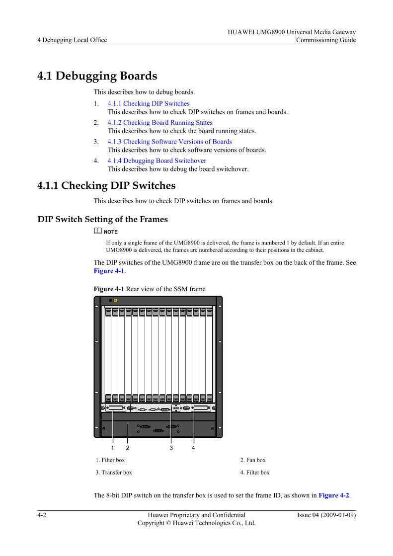
The DIP switches of the UMG8900 frame are on the transfer box on the back of the frame. SeeFigure 4-1.
Figure 4-1 Rear view of the SSM frame
1 2 3 4
1. Filter box 2. Fan box
3. Transfer box 4. Filter box
The 8-bit DIP switch on the transfer box is used to set the frame ID, as shown in Figure 4-2.
4 Debugging Local OfficeHUAWEI UMG8900 Universal Media Gateway
Commissioning Guide
4-2 Huawei Proprietary and ConfidentialCopyright © Huawei Technologies Co., Ltd.
Issue 04 (2009-01-09)
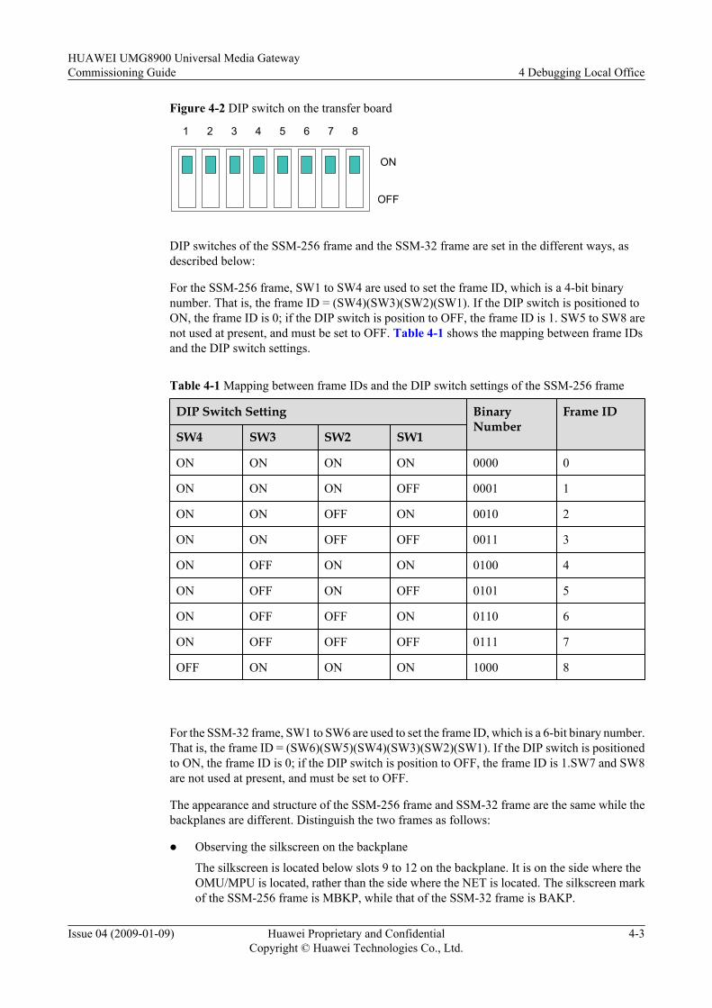
Figure 4-2 DIP switch on the transfer board
ON
1 2 3 4 5 6 7 8
OFF
DIP switches of the SSM-256 frame and the SSM-32 frame are set in the different ways, asdescribed below:
For the SSM-256 frame, SW1 to SW4 are used to set the frame ID, which is a 4-bit binarynumber. That is, the frame ID = (SW4)(SW3)(SW2)(SW1). If the DIP switch is positioned toON, the frame ID is 0; if the DIP switch is position to OFF, the frame ID is 1. SW5 to SW8 arenot used at present, and must be set to OFF. Table 4-1 shows the mapping between frame IDsand the DIP switch settings.
Table 4-1 Mapping between frame IDs and the DIP switch settings of the SSM-256 frame
DIP Switch Setting BinaryNumber
Frame ID
SW4 SW3 SW2 SW1
ON ON ON ON 0000 0
ON ON ON OFF 0001 1
ON ON OFF ON 0010 2
ON ON OFF OFF 0011 3
ON OFF ON ON 0100 4
ON OFF ON OFF 0101 5
ON OFF OFF ON 0110 6
ON OFF OFF OFF 0111 7
OFF ON ON ON 1000 8
For the SSM-32 frame, SW1 to SW6 are used to set the frame ID, which is a 6-bit binary number.That is, the frame ID = (SW6)(SW5)(SW4)(SW3)(SW2)(SW1). If the DIP switch is positionedto ON, the frame ID is 0; if the DIP switch is position to OFF, the frame ID is 1.SW7 and SW8are not used at present, and must be set to OFF.
The appearance and structure of the SSM-256 frame and SSM-32 frame are the same while thebackplanes are different. Distinguish the two frames as follows:
l Observing the silkscreen on the backplane
The silkscreen is located below slots 9 to 12 on the backplane. It is on the side where theOMU/MPU is located, rather than the side where the NET is located. The silkscreen markof the SSM-256 frame is MBKP, while that of the SSM-32 frame is BAKP.
HUAWEI UMG8900 Universal Media GatewayCommissioning Guide 4 Debugging Local Office
Issue 04 (2009-01-09) Huawei Proprietary and ConfidentialCopyright © Huawei Technologies Co., Ltd.
4-3

l Observing the slot on the backplaneThere are 16 slots on the front and back of the backplane of the SSM-256 framerespectively.The width of the slots is the same. Because each OMB/MPB/TNC boardoccupies two physical slots in the SSM-32 frame, their corresponding slots on the backplanealso occupy two slots. That is, there are 14 slots on the front and back of the backplane ofthe SSM-32 frame respectively, and the two slots in the middle are wider than the otherslots.
DIP Switch Setting of the Boardsl DIP Switches of the UG01ME32
CAUTIONThe 32 E1 cables connected with the ME32 must be of the same impedance value. That is,an E32 board cannot be connected with both 75-ohm E1 cables and 120-ohm E1 cables.
Table 4-2 lists the DIP switches of the UG01ME32.
Table 4-2 DIP switches of the UG01ME32
Function Name Bit Range of E1 Interfaces
Setting thegrounding modesfor the E1 cables
S2 1 to 8 16 to 23
S3 1 to 8 24 to 31
S4 1 to 8 0 to 7
S5 1 to 8 8 to 15
Setting theimpedance valuesthat match the E1cables
S6 1 to 8 24 to 27
S7 1 to 8 20 to 23
S8 1 to 8 28 to 31
S9 1 to 8 0 to 3
S10 1 to 8 4 to 7
S11 1 to 8 8 to 11
S12 1 to 8 12 to 15
S13 1 to 8 16 to 19
Reporting theattributes of the E1cables
S14 1 to 2 0 to 31
Table 4-3 and Table 4-4 list the methods to set the DIP switches of the UG01ME32.
4 Debugging Local OfficeHUAWEI UMG8900 Universal Media Gateway
Commissioning Guide
4-4 Huawei Proprietary and ConfidentialCopyright © Huawei Technologies Co., Ltd.
Issue 04 (2009-01-09)
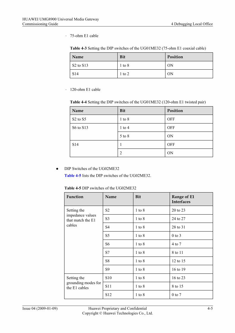
– 75-ohm E1 cable
Table 4-3 Setting the DIP switches of the UG01ME32 (75-ohm E1 coaxial cable)
Name Bit Position
S2 to S13 1 to 8 ON
S14 1 to 2 ON
– 120-ohm E1 cable
Table 4-4 Setting the DIP switches of the UG01ME32 (120-ohm E1 twisted pair)
Name Bit Position
S2 to S5 1 to 8 OFF
S6 to S13 1 to 4 OFF
5 to 8 ON
S14 1 OFF
2 ON
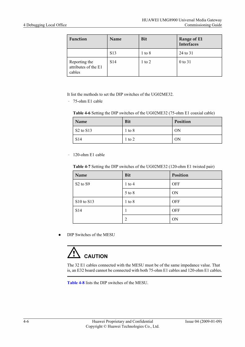
l DIP Switches of the UG02ME32
Table 4-5 lists the DIP switches of the UG02ME32.
Table 4-5 DIP switches of the UG02ME32
Function Name Bit Range of E1Interfaces
Setting theimpedance valuesthat match the E1cables
S2 1 to 8 20 to 23
S3 1 to 8 24 to 27
S4 1 to 8 28 to 31
S5 1 to 8 0 to 3
S6 1 to 8 4 to 7
S7 1 to 8 8 to 11
S8 1 to 8 12 to 15
S9 1 to 8 16 to 19
Setting thegrounding modes forthe E1 cables
S10 1 to 8 16 to 23
S11 1 to 8 8 to 15
S12 1 to 8 0 to 7
HUAWEI UMG8900 Universal Media GatewayCommissioning Guide 4 Debugging Local Office
Issue 04 (2009-01-09) Huawei Proprietary and ConfidentialCopyright © Huawei Technologies Co., Ltd.
4-5
Function Name Bit Range of E1Interfaces
S13 1 to 8 24 to 31
Reporting theattributes of the E1cables
S14 1 to 2 0 to 31
It list the methods to set the DIP switches of the UG02ME32.– 75-ohm E1 cable
Table 4-6 Setting the DIP switches of the UG02ME32 (75-ohm E1 coaxial cable)
Name Bit Position
S2 to S13 1 to 8 ON
S14 1 to 2 ON
– 120-ohm E1 cable
Table 4-7 Setting the DIP switches of the UG02ME32 (120-ohm E1 twisted pair)
Name Bit Position
S2 to S9 1 to 4 OFF
5 to 8 ON
S10 to S13 1 to 8 OFF
S14 1 OFF
2 ON
l DIP Switches of the MESU
CAUTIONThe 32 E1 cables connected with the MESU must be of the same impedance value. Thatis, an E32 board cannot be connected with both 75-ohm E1 cables and 120-ohm E1 cables.
Table 4-8 lists the DIP switches of the MESU.
4 Debugging Local OfficeHUAWEI UMG8900 Universal Media Gateway
Commissioning Guide
4-6 Huawei Proprietary and ConfidentialCopyright © Huawei Technologies Co., Ltd.
Issue 04 (2009-01-09)
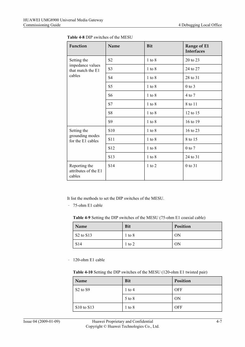
Table 4-8 DIP switches of the MESU
Function Name Bit Range of E1Interfaces
Setting theimpedance valuesthat match the E1cables
S2 1 to 8 20 to 23
S3 1 to 8 24 to 27
S4 1 to 8 28 to 31
S5 1 to 8 0 to 3
S6 1 to 8 4 to 7
S7 1 to 8 8 to 11
S8 1 to 8 12 to 15
S9 1 to 8 16 to 19
Setting thegrounding modesfor the E1 cables
S10 1 to 8 16 to 23
S11 1 to 8 8 to 15
S12 1 to 8 0 to 7
S13 1 to 8 24 to 31
Reporting theattributes of the E1cables
S14 1 to 2 0 to 31
It list the methods to set the DIP switches of the MESU.– 75-ohm E1 cable
Table 4-9 Setting the DIP switches of the MESU (75-ohm E1 coaxial cable)
Name Bit Position
S2 to S13 1 to 8 ON
S14 1 to 2 ON
– 120-ohm E1 cable
Table 4-10 Setting the DIP switches of the MESU (120-ohm E1 twisted pair)
Name Bit Position
S2 to S9 1 to 4 OFF
5 to 8 ON
S10 to S13 1 to 8 OFF
HUAWEI UMG8900 Universal Media GatewayCommissioning Guide 4 Debugging Local Office
Issue 04 (2009-01-09) Huawei Proprietary and ConfidentialCopyright © Huawei Technologies Co., Ltd.
4-7

Name Bit Position
S14 1 OFF
2 ON
l DIP Switches of the UG01MT32
CAUTIONThe default setting of the DIP switches on the MT32 and the MTSU is 100 ohm.
Table 4-11 lists the DIP switches of the UG01MT32.
Table 4-11 DIP switches of the UG01MT32
Function Name Bit Range of E1Interfaces
Setting thegrounding modesfor the T1 cables
S2 1 to 8 16 to 23
S3 1 to 8 24 to 31
S4 1 to 8 0 to 7
S5 1 to 8 8 to 15
Setting theimpedance valuesthat match the T1cables
S6 1 to 8 24 to 27
S7 1 to 8 20 to 23
S8 1 to 8 28 to 31
S9 1 to 8 0 to 3
S10 1 to 8 4 to 7
S11 1 to 8 8 to 11
S12 1 to 8 12 to 15
S13 1 to 8 16 to 19
Reporting theattributes of the T1cables
S14 1 to 2 0 to 31
Table 4-12 lists the methods to set the DIP switches of the UG01MT32.
4 Debugging Local OfficeHUAWEI UMG8900 Universal Media Gateway
Commissioning Guide
4-8 Huawei Proprietary and ConfidentialCopyright © Huawei Technologies Co., Ltd.
Issue 04 (2009-01-09)
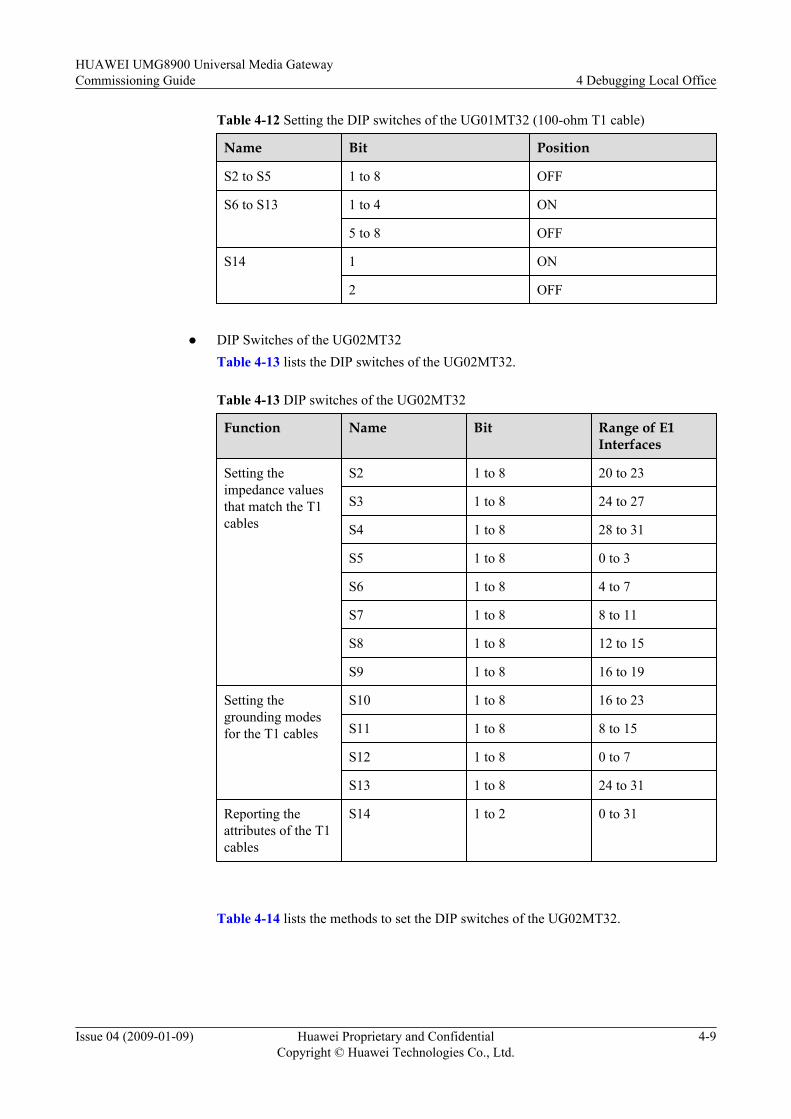
Table 4-12 Setting the DIP switches of the UG01MT32 (100-ohm T1 cable)
Name Bit Position
S2 to S5 1 to 8 OFF
S6 to S13 1 to 4 ON
5 to 8 OFF
S14 1 ON
2 OFF
l DIP Switches of the UG02MT32
Table 4-13 lists the DIP switches of the UG02MT32.
Table 4-13 DIP switches of the UG02MT32
Function Name Bit Range of E1Interfaces
Setting theimpedance valuesthat match the T1cables
S2 1 to 8 20 to 23
S3 1 to 8 24 to 27
S4 1 to 8 28 to 31
S5 1 to 8 0 to 3
S6 1 to 8 4 to 7
S7 1 to 8 8 to 11
S8 1 to 8 12 to 15
S9 1 to 8 16 to 19
Setting thegrounding modesfor the T1 cables
S10 1 to 8 16 to 23
S11 1 to 8 8 to 15
S12 1 to 8 0 to 7
S13 1 to 8 24 to 31
Reporting theattributes of the T1cables
S14 1 to 2 0 to 31
Table 4-14 lists the methods to set the DIP switches of the UG02MT32.
HUAWEI UMG8900 Universal Media GatewayCommissioning Guide 4 Debugging Local Office
Issue 04 (2009-01-09) Huawei Proprietary and ConfidentialCopyright © Huawei Technologies Co., Ltd.
4-9
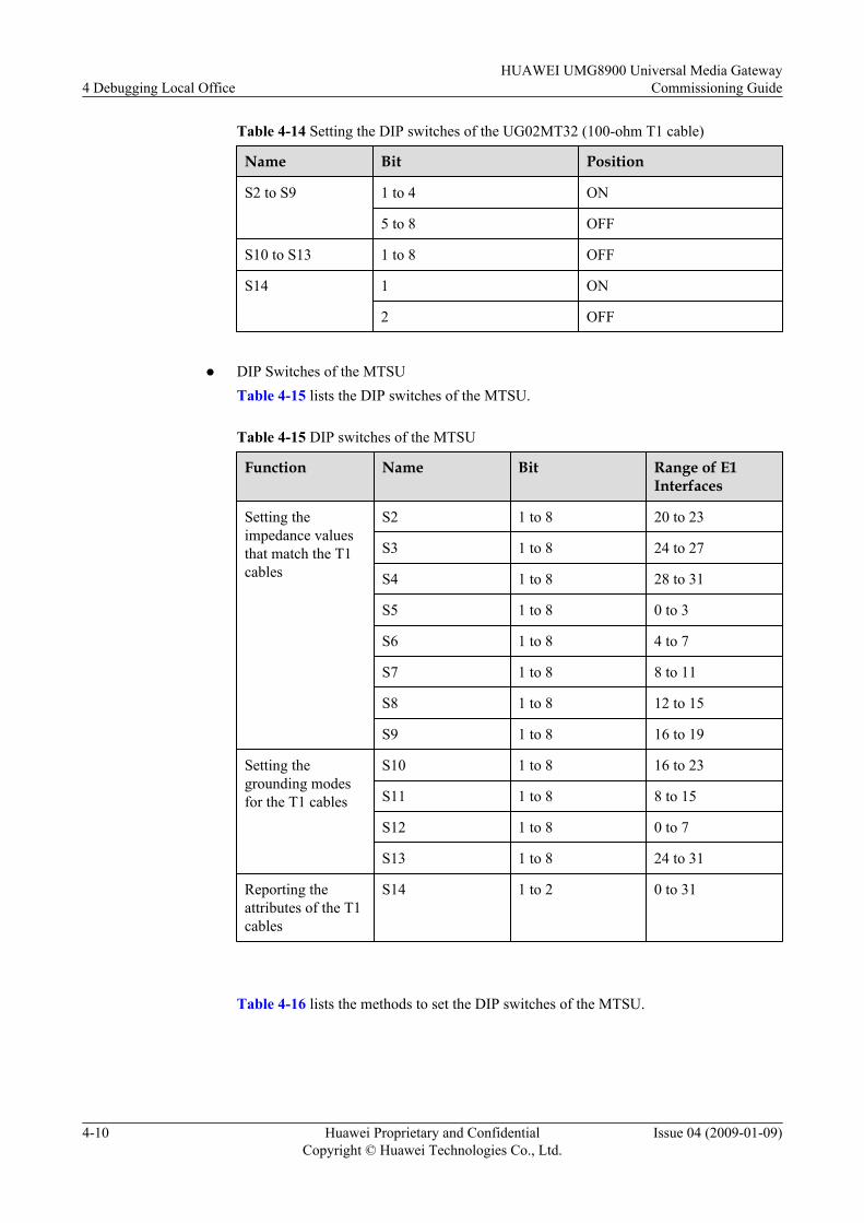
Table 4-14 Setting the DIP switches of the UG02MT32 (100-ohm T1 cable)
Name Bit Position
S2 to S9 1 to 4 ON
5 to 8 OFF
S10 to S13 1 to 8 OFF
S14 1 ON
2 OFF
l DIP Switches of the MTSU
Table 4-15 lists the DIP switches of the MTSU.
Table 4-15 DIP switches of the MTSU
Function Name Bit Range of E1Interfaces
Setting theimpedance valuesthat match the T1cables
S2 1 to 8 20 to 23
S3 1 to 8 24 to 27
S4 1 to 8 28 to 31
S5 1 to 8 0 to 3
S6 1 to 8 4 to 7
S7 1 to 8 8 to 11
S8 1 to 8 12 to 15
S9 1 to 8 16 to 19
Setting thegrounding modesfor the T1 cables
S10 1 to 8 16 to 23
S11 1 to 8 8 to 15
S12 1 to 8 0 to 7
S13 1 to 8 24 to 31
Reporting theattributes of the T1cables
S14 1 to 2 0 to 31
Table 4-16 lists the methods to set the DIP switches of the MTSU.
4 Debugging Local OfficeHUAWEI UMG8900 Universal Media Gateway
Commissioning Guide
4-10 Huawei Proprietary and ConfidentialCopyright © Huawei Technologies Co., Ltd.
Issue 04 (2009-01-09)

Table 4-16 Setting the DIP switches of the MTSU (100-ohm T1 cable)
Name Bit Position
S2 to S9 1 to 4 ON
5 to 8 OFF
S10 to S13 1 to 8 OFF
S14 1 ON
2 OFF
PostrequisiteAfter checking the DIP switch, check the running status of boards.
4.1.2 Checking Board Running StatesThis describes how to check the board running states.
Procedure
Step 1 Start the local maintenance terminal (LMT). On the bottom of the left navigation pane, click theDevice Panel tab and click Device Management . Then you can view the running states ofboards.
NOTE
The MML Command and Device Panel windows on the LMT can be switched by pressing F4.
Step 2 Check the board color. Table 4-17 lists the meanings of the board colors.
Figure 4-3 shows the displayed board colors.
Figure 4-3 Board color
HUAWEI UMG8900 Universal Media GatewayCommissioning Guide 4 Debugging Local Office
Issue 04 (2009-01-09) Huawei Proprietary and ConfidentialCopyright © Huawei Technologies Co., Ltd.
4-11

Table 4-17 Meanings of the colors indicating the board states
State Meaning
Uninstalled The board is not installed in the slot that is configured.
Unconfigured The board is inserted but not configured.
Inconsistent The configuration of the board is inconsistent with the actualconfiguration.
Isolated Normal The board is normal but does not process services.
Fault The board is faulty.
Standby Normal The slave board operating in 1+1 backup mode is normal.
Backuping The slave board is being synchronized with the master board.
Normal The board works normally.
GroupingNormal
The board that has been grouped is normal.
Grouping Fault The board that has been grouped is faulty.
----End
PostrequisiteAfter checking the running state of the board, check the software version of the board.
4.1.3 Checking Software Versions of BoardsThis describes how to check software versions of boards.
PrerequisiteIf the board runs normally, check whether software versions of boards are correct.
Procedure
Step 1 On the local maintenance terminal (LMT), run LST BRDVER or right-click a board and selectBoard Version Info.
Step 2 Then check whether the software version of the board meets the planning requirement.
----End
PostrequisiteAfter checking software versions of boards, debug board switchover.
4.1.4 Debugging Board SwitchoverThis describes how to debug the board switchover.
4 Debugging Local OfficeHUAWEI UMG8900 Universal Media Gateway
Commissioning Guide
4-12 Huawei Proprietary and ConfidentialCopyright © Huawei Technologies Co., Ltd.
Issue 04 (2009-01-09)
ContextIn the carrier-class application, the devices must have a high self-protection capability, and thusslave boards (1+1 backup boards) are configured for most boards.
The following boards can be in 1+1 backup mode: the OMU, MPU, NET, TNU, CMU, CLK,HRB, ASU, and BLU.
The following boards can use the 1+1 backup mode: the S1L, S2L, and PIE.
In normal conditions, the master board is working. When the master board fails, the slave boardswitches to be the master and takes over the work. Thus, it is necessary to check board switchoverduring the system commissioning.
ProcedureStep 1 Run SWP BRD or right-click a master board on the device panel and select Swap Board to
implement board switchover.
Step 2 After board switchover, check whether the master board can change to the slave board and theslave board can change to the master board. You can run LST BRD to check the master/slavestate of the board.
Step 3 Switch over the board during a call, and check whether the call is affected.
Step 4 Run SWP BRD to switch the board.
----End
4.2 Debugging ClockThis describes how to debug the clock.
ContextThe phase-lock state of the clock can be:
l Free running: specifies that the CLK outputs free running clock generated by its crystal.
l Fast tracking: specifies that the CLK or the clock subboard on the MTNC is trackingreference source clock fast and is an instantaneous state usually when the system justconnects the reference source.
l Locked: specifies that the CLK or the clock subboard on the MTNC has locked the primaryreference source and outputs clock signals aligned with reference source.
l Holdover: specifies that the CLK or the clock subboard on the MTNC outputs clock signalsbased on the locked state when reference source is missing.
After the clock reference source is configured, the phase-lock state of the CLK or the clocksubboard on the MTNC is Locked when the system is in normal operation. Otherwise, the clockis abnormal. Check whether the clock cables are correctly connected and whether the clock-related alarm occurs. If yes, locate the fault and find the causes.
If no reference source data is configured and the CLK or the clock subboard on the MTNC adoptsthe clock generated by its constant-temperature crystal, the phase-lock state is Free running.
When constituting a digital network, stored program control switches are connected through thedigital transmission system. The clock frequency and phase of all the switches must be
HUAWEI UMG8900 Universal Media GatewayCommissioning Guide 4 Debugging Local Office
Issue 04 (2009-01-09) Huawei Proprietary and ConfidentialCopyright © Huawei Technologies Co., Ltd.
4-13
consistent. Therefore, all the switches in the network must be of the same sending clockfrequency and receiving clock frequency. The drift and jitter of a clock may cause many issues,such as call noise, call disconnection, and digital service interruption.
Only how to debug the clock system is described here. For some faults occurring during thedebugging, see the HUAWEI UMG8900 Universal Media Gateway TroubleshootingClearingClock System Faults.
4.2.1 Checking Clock CablesThis describes how to check connections of clock cables.
4.2.2 Debugging Networking of Single Reference SourceThis describes how to debug the clock of the single reference source networking.
4.2.3 Debugging Networking of Multiple Reference SourceThis describes how to debug the clock of the networking of the multiple reference sources.
4.2.1 Checking Clock CablesThis describes how to check connections of clock cables.
ContextThe SSM-256 and SSM-32 frames provide the stratum-2 clock through the CLK. The SSM-32frame can provide the stratum-3 clock through the clock subboard of the MTNC.
Procedure
Step 1 If the UMG8900 locks the BITS clock, connect 2 Mbit/s clock cables from the BITS to 2M_INinterfaces on the master and slave CLKs in the main control frame respectively.
This operation can be skipped if the UMG8900 locks the clock of the peer office or the GPSclock.
Step 2 If the UMG8900 locks the peer office clock (line clock 1 or line clock 2), connect the X1connector of the 8 kHz line clock cable to the 8K_OUT interface on the TDM interface board(including E32/T32/S2L) and the X2/X3 connector to the 8K_IN1 or 8K_IN2 interface on themaster and slave CLKs/MTNCs. 8K_IN1 indicates to lock Line Clock 1 and 8K_IN2 indicatesto lock line clock 2.
This operation can be skipped if the UMG8900 locks the BITS clock or the GPS clock.
If the main control frame is an SSM-256 frame, connect the X2/X3 connector of the line clockcable to the CLK. If the main control frame is an SSM-32 frame, connect the X2/X3 connectorof the line clock to the MTNC.
Step 3 If the UMG8900 locks the GPS clock, connect one end of the GPS clock cable to the ANTinterface on the CLK board and the other end to the GPS satellite antenna.
This operation can be skipped if the UMG8900 locks the clock of the peer office or the BITSclock.
Only the CLK in the SSM-256 frame supports the GPS clock. The clock subboard of the MTNCin the SSM-32 frame cannot lock the GPS clock.
Step 4 In terms of connecting clock distribution cables, connect the X1 connector of the clockdistribution cable to the CLK_OUT interface on the CLK in the main control frame and X2 toX7 connectors to the CLK_IN interfaces on the NETs in other frames. The two CLK_IN
4 Debugging Local OfficeHUAWEI UMG8900 Universal Media Gateway
Commissioning Guide
4-14 Huawei Proprietary and ConfidentialCopyright © Huawei Technologies Co., Ltd.
Issue 04 (2009-01-09)
interfaces on the NET, CLK0_IN and CLK1_IN, are respectively connected with CLK_OUTinterfaces on the master and slave CLKs.
This operation can be skipped in single-frame mode.
When the SSM-32 frames are cascaded by themselves, the clock signals are transmitted throughthe TDM cascading fiber. Thus, the clock distribution cable is not required. In this case, thisitem is not checked.
When the SSM-256 frames are cascaded by themselves, this item must be checked.
When the SSM-32 frame and the SSM-256 frame are cascaded, the SSM-32 frame does notrequire any clock distribution cable; however, the SSM-256 frame requires the clock distributioncable. In this case, check this item for the SSM-256 frame only.
Step 5 In terms of connecting clock output cables, connect 2M_OUT interfaces on the CLK or MTNCto CLK_IN interfaces on the receiving device with 2 Mbit/s clock cables.
This operation can be skipped when no junior office locks the UMG8900 clock.
----End
4.2.2 Debugging Networking of Single Reference SourceThis describes how to debug the clock of the single reference source networking.
ContextNOTE
Step 1 and Step 2 are required only when the peer office clock is locked. If the global positioning system(GPS) or building integrated timing supply system (BITS) clock is locked, skip these two steps.
Procedure
Step 1 Run DSP E1PORT without specifying the port No. to check the local E1 port that locks thepeer E1 line clock is normal.
The E32 can extract the peer E1 line clock only when the local E1 port is in the OK state. Youcan also observe the color of the E1 port on the device management panel to judge its status.Green means the port runs well.
Step 2 Run DSP SLIP to perform statistics on the total slips in the latest 15 minutes or 24 hours.
Step 3 Run DSP CLK to display the state of the clock phase-locked loop on the CLK and the states ofreference sources. Use different debugging methods based on the output results.l If the phase-lock state is trace, it indicates that the clock phase-locked loop on the CLK can
trace the reference source clock. Then perform Step 4.l If the phase-lock state is free running, it indicates that the clock phase-locked loop on the
CLK cannot trace the reference source clock. Then perform Step 5.
NOTE
It takes about 30 minutes for the CLK to complete clock locking.
Step 4 Run LST CLK to check whether the clock data configuration is correct.
After handling the configuration errors and faults, repeat Step 1, Step 2, and Step 3.
HUAWEI UMG8900 Universal Media GatewayCommissioning Guide 4 Debugging Local Office
Issue 04 (2009-01-09) Huawei Proprietary and ConfidentialCopyright © Huawei Technologies Co., Ltd.
4-15
Step 5 Check whether the clock reference source, CLK, and clock subboard fail. Check whether theclock-related alarm exists in the alarm management system. For example, if ALM_2203Frequency offset of the master reference exceeds scope occurs, it indicates that the phase lockfailure is caused by the poor quality of the reference source. If the clock-related alarm exists,clear the faults.
----End
4.2.3 Debugging Networking of Multiple Reference SourceThis describes how to debug the clock of the networking of the multiple reference sources.
Context
Multiple clock reference sources can be configured on the UMG8900. When the quality of themaster reference source cannot meet the requirement, the system can automatically switch tothe slave reference source.
For example, the building integrated timing supply system (BITS) clock reference source(namely external synchronization reference source) and line clock reference source 1 (extractingclock signals from the peer office) are configured on the UMG8900. In normal conditions, theUMG8900 locks the BITS clock. When the UMG8900 fails to trace the BITS clock, it canautomatically switch to lock the peer office clock.
When multiple reference sources are configured, check whether the reference sources can benormally switched over.
Suppose the BITS clock reference source and line clock reference source 1 are configured. TheBITS is of a higher priority level and the UMG8900 extracts clock signals from the BITS bydefault. When the UMG8900 fails to trace the BITS, it automatically switches to line clockreference source 1. When the BITS clock signals are available, the UMG8900 automaticallyrelock the BITS clock.
Procedure
Step 1 Check whether the master reference source of the CLK is normal according to 4.2.2 DebuggingNetworking of Single Reference Source.
Step 2 Pull the clock cables out of the 2M_IN interfaces on the master and slave CLKs.
Then, the alarms ALM_2202 Reference Source Losing and ALM_2209 Phase Locking StatusSwitch occur, and the phase-locked state changes from locked to holdover.
Step 3 10 minutes later, run DSP CLK to check whether the slave reference source is locked.
When the phase-locked state is locked, it indicates that the master reference source is switchedto line clock 1.
NOTE
After the CLK relocks the slave reference source, ALM_2209 Phase Locking Status Switch occurs, andthe phase-locked state changes from holdover to locked.
Step 4 Reconnect the master reference source cables. 10 minutes later, run DSP CLK to check whetherthe master reference source is locked.
4 Debugging Local OfficeHUAWEI UMG8900 Universal Media Gateway
Commissioning Guide
4-16 Huawei Proprietary and ConfidentialCopyright © Huawei Technologies Co., Ltd.
Issue 04 (2009-01-09)
The phase-lock state is locked, and the master reference source switches to the externalsynchronization reference source. The external synchronization reference source refers to theBITS clock.
----End
4.3 Debugging System TimeThis describes how to debug the system time.
4.3.1 Checking Time Synchronization ModeThis describes how to check the time synchronization mode.
4.3.2 Checking Time ZoneThis describes how to check the time zone.
4.3.3 Checking NTP ServerThis describes how to check the settings of the Network Time Protocol (NTP) server.
4.3.4 Checking Settings of Daylight Saving TimeThis describes how to check the settings of daylight saving time (DST).
4.3.1 Checking Time Synchronization ModeThis describes how to check the time synchronization mode.
ContextRun LST TIMESYC to check the time synchronization mode. Three time synchronizationmodes are listed as follows:
l Global positioning system (GPS) mode: GPS satellite signals are obtained to synchronizethe local system time.
l Network Time Protocol (NTP) mode: The NTP is used to synchronize the time with theNTP server through the network.
l Real Time Transport Protocol (RTC) mode: The UMG8900 does not synchronize with theexternal and completely depends on the RTC clock.
By default, the RTC mode is used.
4.3.2 Checking Time ZoneThis describes how to check the time zone.
ProcedureIf the Network Time Protocol (NTP) or global positioning system (GPS) mode is used to obtaintime, you must check the setting of the time zone. Run LST TZ to check the time zone.GMT_1200 to GMT_0100 indicate the west time zones. GMT+0100 to GMT+1400 indicate theeast time zones. GMT refers to Greenwich Mean Time. Run SET TZ to set the time zone. Then,the system coverts the Greenwich Mean Time (GMT) to the local time.
----End
HUAWEI UMG8900 Universal Media GatewayCommissioning Guide 4 Debugging Local Office
Issue 04 (2009-01-09) Huawei Proprietary and ConfidentialCopyright © Huawei Technologies Co., Ltd.
4-17
4.3.3 Checking NTP ServerThis describes how to check the settings of the Network Time Protocol (NTP) server.
ProcedureIf the NTP mode is used to obtain time, you must check the settings of the NTP server. RunLST NTPSRV to check the settings of the NTP server. Run DSP NTP to display the runningstate of the NTP server.
----End
4.3.4 Checking Settings of Daylight Saving TimeThis describes how to check the settings of daylight saving time (DST).
ProcedureIf DST is set, you must check whether the DST settings are correct. Run LST TZ to check theDST settings.
----End
4.4 Debugging CascadingThis describes how to debug cascading.
4.4.1 SSM-256 Self-CascadingThis describes the SSM-256 self-cascading.
4.4.2 SSM-32 Self-CascadingThis describes the SSM-32 self-cascading.
4.4.3 SSM-256 and SSM-32 Mixed Cascading (UG01NET and BLU.A Configured)This describes the SSM-256 and SSM-32 mixed cascading when the UG01NET works with theBLU.A.
4.4.4 SSM-256 and SSM-32 Mixed Cascading (UG02NET and BLU.C Configured)This describes the SSM-256 and SSM-32 mixed cascading when the UG02NET works with theBLU.C.
4.4.5 Process of Cascading SwitchoverThis describes the process of cascading switchover.
4.4.6 Checking Cascading Cable ConnectionThis describes how to check the cable connection of the SSM-32 and SSM-256 self-cascadingand mixed cascading.
4.4.7 Checking Cascading Configurations and States of Cascading BoardsThis describes how to check cascading configurations and states of cascading boards.
4.4.8 Debugging FE CascadingThis describes how to debug fast Ethernet (FE) interface cascading.
4.4.9 Debugging TDM CascadingThis describes how to debug the time division multiplexing (TDM) interface cascading.
4 Debugging Local OfficeHUAWEI UMG8900 Universal Media Gateway
Commissioning Guide
4-18 Huawei Proprietary and ConfidentialCopyright © Huawei Technologies Co., Ltd.
Issue 04 (2009-01-09)
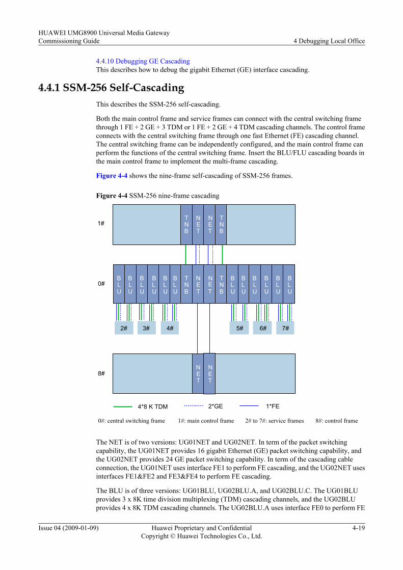
4.4.10 Debugging GE CascadingThis describes how to debug the gigabit Ethernet (GE) interface cascading.
4.4.1 SSM-256 Self-CascadingThis describes the SSM-256 self-cascading.
Both the main control frame and service frames can connect with the central switching framethrough 1 FE + 2 GE + 3 TDM or 1 FE + 2 GE + 4 TDM cascading channels. The control frameconnects with the central switching frame through one fast Ethernet (FE) cascading channel.The central switching frame can be independently configured, and the main control frame canperform the functions of the central switching frame. Insert the BLU/FLU cascading boards inthe main control frame to implement the multi-frame cascading.
Figure 4-4 shows the nine-frame self-cascading of SSM-256 frames.
Figure 4-4 SSM-256 nine-frame cascading
2# 3# 4# 6# 7#
0#
1#
8#
4*8 K TDM 1*FE
NET
NET
TNB
TNB
NET
NET
TNB
TNB
BLU
BLU
BLU
BLU
BLU
BLU
BLU
BLU
BLU
BLU
BLU
BLU
NET
NET
5#
2*GE
0#: central switching frame 1#: main control frame 2# to 7#: service frames 8#: control frame
The NET is of two versions: UG01NET and UG02NET. In term of the packet switchingcapability, the UG01NET provides 16 gigabit Ethernet (GE) packet switching capability, andthe UG02NET provides 24 GE packet switching capability. In term of the cascading cableconnection, the UG01NET uses interface FE1 to perform FE cascading, and the UG02NET usesinterfaces FE1&FE2 and FE3&FE4 to perform FE cascading.
The BLU is of three versions: UG01BLU, UG02BLU.A, and UG02BLU.C. The UG01BLUprovides 3 x 8K time division multiplexing (TDM) cascading channels, and the UG02BLUprovides 4 x 8K TDM cascading channels. The UG02BLU.A uses interface FE0 to perform FE
HUAWEI UMG8900 Universal Media GatewayCommissioning Guide 4 Debugging Local Office
Issue 04 (2009-01-09) Huawei Proprietary and ConfidentialCopyright © Huawei Technologies Co., Ltd.
4-19
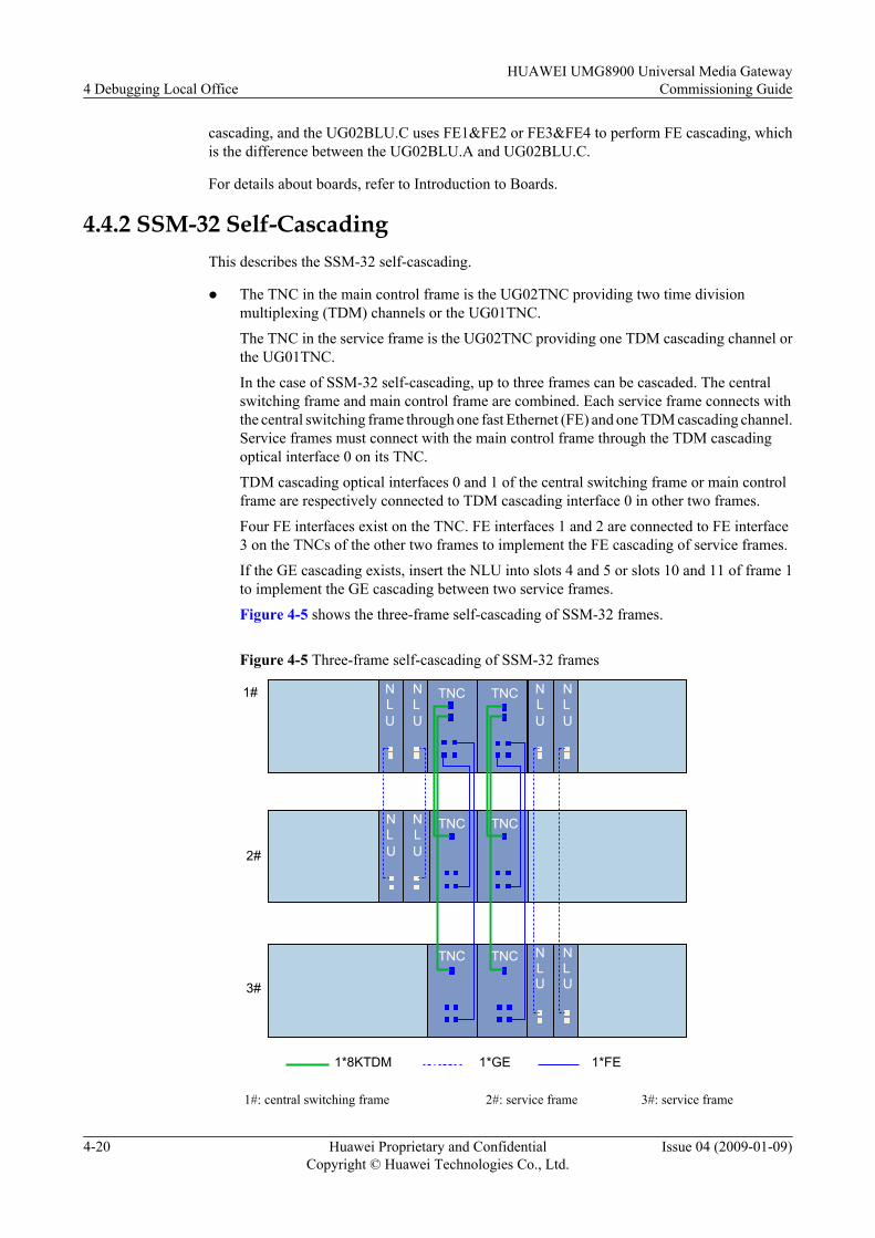
cascading, and the UG02BLU.C uses FE1&FE2 or FE3&FE4 to perform FE cascading, whichis the difference between the UG02BLU.A and UG02BLU.C.
For details about boards, refer to Introduction to Boards.
4.4.2 SSM-32 Self-CascadingThis describes the SSM-32 self-cascading.
l The TNC in the main control frame is the UG02TNC providing two time divisionmultiplexing (TDM) channels or the UG01TNC.
The TNC in the service frame is the UG02TNC providing one TDM cascading channel orthe UG01TNC.
In the case of SSM-32 self-cascading, up to three frames can be cascaded. The centralswitching frame and main control frame are combined. Each service frame connects withthe central switching frame through one fast Ethernet (FE) and one TDM cascading channel.Service frames must connect with the main control frame through the TDM cascadingoptical interface 0 on its TNC.
TDM cascading optical interfaces 0 and 1 of the central switching frame or main controlframe are respectively connected to TDM cascading interface 0 in other two frames.
Four FE interfaces exist on the TNC. FE interfaces 1 and 2 are connected to FE interface3 on the TNCs of the other two frames to implement the FE cascading of service frames.
If the GE cascading exists, insert the NLU into slots 4 and 5 or slots 10 and 11 of frame 1to implement the GE cascading between two service frames.
Figure 4-5 shows the three-frame self-cascading of SSM-32 frames.
Figure 4-5 Three-frame self-cascading of SSM-32 frames
TNC TNC
TNC TNC
TNC TNC1#
1*8KTDM 1*FE
2#
3#
NLU
NLU
NLU
NLU
1*GE
NLU
NLU
NLU
NLU
1#: central switching frame 2#: service frame 3#: service frame
4 Debugging Local OfficeHUAWEI UMG8900 Universal Media Gateway
Commissioning Guide
4-20 Huawei Proprietary and ConfidentialCopyright © Huawei Technologies Co., Ltd.
Issue 04 (2009-01-09)
l The TNC in the main control frame is the UG02TNC providing four time divisionmultiplexing (TDM) channels. The TNC in the service frame is the UG02TNC providingtwo TDM cascading channels.The UMG8900 supports up to three frames in SSM-32 self-cascading. The centralswitching frame and the main control frame are integrated. The UMG8900 provides fourTDM cascading optical interfaces. The service frame connects to the main control framethrough the 1 FE + 2 TDM cascading channel to implement the 2 x 8 K TDM cascading.The service frame must connect with the main control frame through TDM cascadingoptical interfaces 0 and 1 on the TNC. The TNC provides two TDM cascading opticalinterfaces.Cascading optical interfaces 0 and 1 on the TNC in the central switching and main controlintegrated frame connect to TDM cascading optical interfaces 0 and 1 on the TNC in serviceframe 1. For service frame 1, refer to 2# in Figure 4-6. Cascading optical interfaces 2 and3 on the TNC in the central switching and main control integrated frame connect to TDMcascading optical interfaces 0 and 1 on the TNC in service frame 2. For service frame 2,refer to 3# in Figure 4-6.The TNC provides four FE interfaces. FE interfaces 1 and 2 connect to FE interfaces 3 onthe TNCs in the other two frames to implement the FE cascading with service frames.If the GE cascading exists, insert the NLU into slots 4 and 5 or slots 10 and 11 of frame 1to implement the GE cascading with two service frames.Figure 4-6 shows the three-frame self-cascading of SSM-32 frames.
HUAWEI UMG8900 Universal Media GatewayCommissioning Guide 4 Debugging Local Office
Issue 04 (2009-01-09) Huawei Proprietary and ConfidentialCopyright © Huawei Technologies Co., Ltd.
4-21
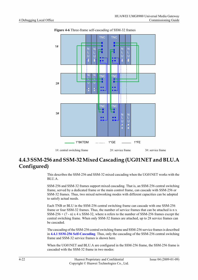
Figure 4-6 Three-frame self-cascading of SSM-32 frames
TNC TNC
TNC TNC
TNC TNC
1#
2#
3#
NLU
NLU
NLU
NLU
NLU
NLU
NLU
NLU
1*8KTDM 1*FE1*GE
1#: central switching frame 2#: service frame 3#: service frame
4.4.3 SSM-256 and SSM-32 Mixed Cascading (UG01NET and BLU.AConfigured)
This describes the SSM-256 and SSM-32 mixed cascading when the UG01NET works with theBLU.A.
SSM-256 and SSM-32 frames support mixed cascading. That is, an SSM-256 central switchingframe, served by a dedicated frame or the main control frame, can cascade with SSM-256 orSSM-32 frames. Thus, two mixed networking modes with different capacities can be adoptedto satisfy actual needs.
Each TNB or BLU in the SSM-256 central switching frame can cascade with one SSM-256frame or four SSM-32 frames. Thus, the number of service frames that can be attached is n xSSM-256 + (7 - n) x 4 x SSM-32, where n refers to the number of SSM-256 frames except thecentral switching frame. When only SSM-32 frames are attached, up to 28 service frames canbe cascaded.
The cascading of the SSM-256 central switching frame and SSM-256 service frames is describedin 4.4.1 SSM-256 Self-Cascading. Thus, only the cascading of the SSM-256 central switchingframe and SSM-32 service frames is shown here.
When the UG01NET and BLU.A are configured in the SSM-256 frame, the SSM-256 frame iscascaded with the SSM-32 frame in two modes:
4 Debugging Local OfficeHUAWEI UMG8900 Universal Media Gateway
Commissioning Guide
4-22 Huawei Proprietary and ConfidentialCopyright © Huawei Technologies Co., Ltd.
Issue 04 (2009-01-09)
l TNB and NET used
l BLU used
TNB and NET Usedl If the TNC in the SSM-32 frame provides one TDM cascading optical interface, the
SSM-256 frame can cascade with four SSM-32 frames, that is, one SSM-32 main controlframe and three SSM-32 service frames.Each SSM-32 service frame connects with the central switching frame through one fastEthernet (FE) and one time division multiplexing (TDM) cascading channel. SSM-32service frames must connect with the central switching frame through TDM cascadingoptical port 0 on the TNC.Figure 4-7 shows the mixed cascading of one SSM-256 frame and four SSM-32 framesthrough the TNB.
HUAWEI UMG8900 Universal Media GatewayCommissioning Guide 4 Debugging Local Office
Issue 04 (2009-01-09) Huawei Proprietary and ConfidentialCopyright © Huawei Technologies Co., Ltd.
4-23

Figure 4-7 Mixed cascading of one SSM-256 frame and four SSM-32 frames through theTNB
TNC TNC
TNC TNC
TNC TNC1#
1*8KTDM 1*FE
2#
3#
0# TNB
TNB
NET
NET
TNC TNC
4#
NLU
NLU
1*GE
0#: central switching frame 1#: main control frame 2# to 4#: service frames
In this mode, the main control frame and the central switching frame are cascaded throughthe TNB to implement the TDM service cascading. The cascading of the control plane isimplemented through the FE cascading interface of the NET.
For the cascading of the GE plane, only one service frame is cascaded. Connect the opticalinterface on the NLU of the service frame to the GE interfaces of the master and slave NETsto implement the GE cascading. The NLU can be configured in slots 4 and 5 or slots 10and 11 of the SSM-32 service frame.
On the FE plane, main control frame 1 connects to the FE interface on the NET in centralswitching frame 0 through the FE3 interface on the TNC. Service frames 2, 3, and 4respectively connect to the FE2, FE1, and FE0 interface in main control frame 1 throughthe FE3 interfaces. Main control frame 1 can be considered as a level-2 cascading frame.
4 Debugging Local OfficeHUAWEI UMG8900 Universal Media Gateway
Commissioning Guide
4-24 Huawei Proprietary and ConfidentialCopyright © Huawei Technologies Co., Ltd.
Issue 04 (2009-01-09)
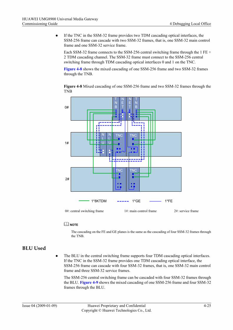
l If the TNC in the SSM-32 frame provides two TDM cascading optical interfaces, theSSM-256 frame can cascade with two SSM-32 frames, that is, one SSM-32 main controlframe and one SSM-32 service frame.
Each SSM-32 frame connects to the SSM-256 central switching frame through the 1 FE +2 TDM cascading channel. The SSM-32 frame must connect to the SSM-256 centralswitching frame through TDM cascading optical interfaces 0 and 1 on the TNC.
Figure 4-8 shows the mixed cascading of one SSM-256 frame and two SSM-32 framesthrough the TNB.
Figure 4-8 Mixed cascading of one SSM-256 frame and two SSM-32 frames through theTNB
TNC TNC
TNC TNC
1#
1*8KTDM 1*FE
2#
0#
TNB
TNB
NET
NET
NLU
NLU
1*GE
0#: central switching frame 1#: main control frame 2#: service frame
NOTE
The cascading on the FE and GE planes is the same as the cascading of four SSM-32 frames throughthe TNB.
BLU Usedl The BLU in the central switching frame supports four TDM cascading optical interfaces.
If the TNC in the SSM-32 frame provides one TDM cascading optical interface, theSSM-256 frame can cascade with four SSM-32 frames, that is, one SSM-32 main controlframe and three SSM-32 service frames.
The SSM-256 central switching frame can be cascaded with four SSM-32 frames throughthe BLU. Figure 4-9 shows the mixed cascading of one SSM-256 frame and four SSM-32frames through the BLU.
HUAWEI UMG8900 Universal Media GatewayCommissioning Guide 4 Debugging Local Office
Issue 04 (2009-01-09) Huawei Proprietary and ConfidentialCopyright © Huawei Technologies Co., Ltd.
4-25
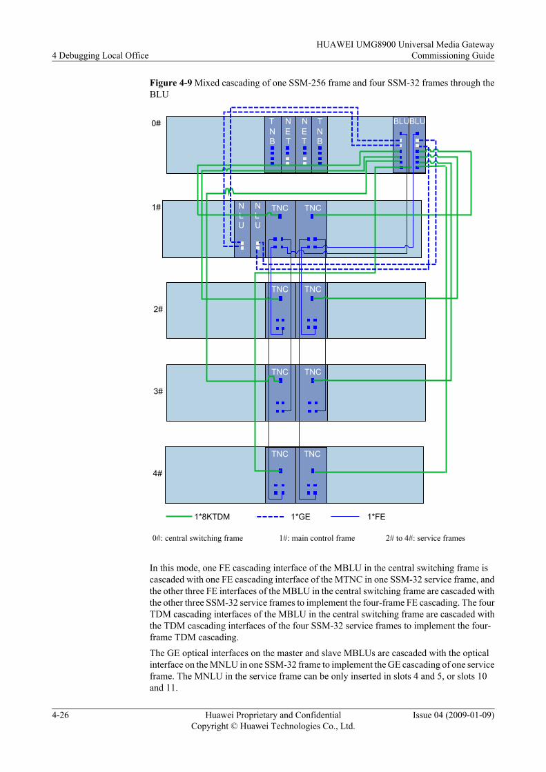
Figure 4-9 Mixed cascading of one SSM-256 frame and four SSM-32 frames through theBLU
TNC TNC
TNC TNC
TNC TNC1#
1*8KTDM 1*FE
2#
3#
0# TNB
TNB
NET
NET
TNC TNC
4#
NLU
NLU
1*GE
BLUBLU
0#: central switching frame 1#: main control frame 2# to 4#: service frames
In this mode, one FE cascading interface of the MBLU in the central switching frame iscascaded with one FE cascading interface of the MTNC in one SSM-32 service frame, andthe other three FE interfaces of the MBLU in the central switching frame are cascaded withthe other three SSM-32 service frames to implement the four-frame FE cascading. The fourTDM cascading interfaces of the MBLU in the central switching frame are cascaded withthe TDM cascading interfaces of the four SSM-32 service frames to implement the four-frame TDM cascading.The GE optical interfaces on the master and slave MBLUs are cascaded with the opticalinterface on the MNLU in one SSM-32 frame to implement the GE cascading of one serviceframe. The MNLU in the service frame can be only inserted in slots 4 and 5, or slots 10and 11.
4 Debugging Local OfficeHUAWEI UMG8900 Universal Media Gateway
Commissioning Guide
4-26 Huawei Proprietary and ConfidentialCopyright © Huawei Technologies Co., Ltd.
Issue 04 (2009-01-09)
l If the TNC in the SSM-32 frame provides two TDM cascading optical interfaces, theSSM-256 frame can cascade with two SSM-32 frames, that is, one SSM-32 main controlframe and one SSM-32 service frame.On the TDM plane, the first SSM-32 frame, main control frame, connects to opticalinterfaces 0 and 1 on the BLU through TDM optical interfaces 0 and 1 on the UG02TNC.The second SSM-32 frame, service frame, connects to optical interfaces 2 and 3 on theBLU through TDM optical interfaces 0 and 1 on the UG02TNC.
NOTE
The cascading on the FE and GE planes is the same as the cascading of four SSM-32 frames throughthe BLU.
4.4.4 SSM-256 and SSM-32 Mixed Cascading (UG02NET and BLU.CConfigured)
This describes the SSM-256 and SSM-32 mixed cascading when the UG02NET works with theBLU.C.
SSM-256 and SSM-32 frames support mixed cascading. That is, an SSM-256 central switchingframe, served by a dedicated frame or the main control frame, can cascade with SSM-256 orSSM-32 frames. Thus, two mixed networking modes with different capacities can be adoptedto satisfy actual needs.
Each TNB or BLU in the SSM-256 central switching frame can cascade with one SSM-256frame or four SSM-32 frames. Thus, the number of service frames that can be attached is n xSSM-256 + (7 - n) x 4 x SSM-32, where n refers to the number of SSM-256 frames except thecentral switching frame. When only SSM-32 frames are attached, up to 28 service frames canbe cascaded.
When the UG02NET and the BLU.C are configured in the SSM-256 frame, the SSM-256 framecan be cascaded with the SSM-32 frame in the following modes:
l TNB used and GE cascading not supported
l TNB used and GE cascading supported
l BLU used and GE cascading not supported
l BLU used and GE cascading supported
TNB and NET Usedl The GE cascading is not supported.
– If the UG01TNC or the UG02TNC in the SSM-32 frame provides one TDM cascadingoptical interface, the SSM-256 frame can cascade with four SSM-32 frames, that is, oneSSM-32 main control frame and three SSM-32 service frames.Figure 4-10 shows the mixed cascading of one SSM-256 frame and four SSM-32 framesthrough the TNB without gigabit Ethernet (GE) cascading.
HUAWEI UMG8900 Universal Media GatewayCommissioning Guide 4 Debugging Local Office
Issue 04 (2009-01-09) Huawei Proprietary and ConfidentialCopyright © Huawei Technologies Co., Ltd.
4-27
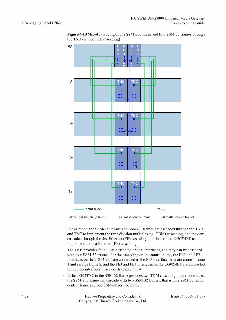
Figure 4-10 Mixed cascading of one SSM-256 frame and four SSM-32 frames throughthe TNB (without GE cascading)
TNC TNC
TNC TNC
TNC TNC1#
1*8KTDM 1*FE
2#
3#
0# TNB
TNB
NET
NET
TNC TNC
4#
0#: central switching frame 1#: main control frame 2# to 4#: service frames
In this mode, the SSM-256 frame and SSM-32 frames are cascaded through the TNBand TNC to implement the time division multiplexing (TDM) cascading; and they arecascaded through the fast Ethernet (FE) cascading interface of the UG02NET toimplement the fast Ethernet (FE) cascading.The TNB provides four TDM cascading optical interfaces, and they can be cascadedwith four SSM-32 frames. For the cascading on the control plane, the FE1 and FE2interfaces on the UG02NET are connected to the FE3 interfaces in main control frame1 and service frame 2, and the FE3 and FE4 interfaces on the UG02NET are connectedto the FE3 interfaces in service frames 3 and 4.
– If the UG02TNC in the SSM-32 frame provides two TDM cascading optical interfaces,the SSM-256 frame can cascade with two SSM-32 frames, that is, one SSM-32 maincontrol frame and one SSM-32 service frame.
4 Debugging Local OfficeHUAWEI UMG8900 Universal Media Gateway
Commissioning Guide
4-28 Huawei Proprietary and ConfidentialCopyright © Huawei Technologies Co., Ltd.
Issue 04 (2009-01-09)
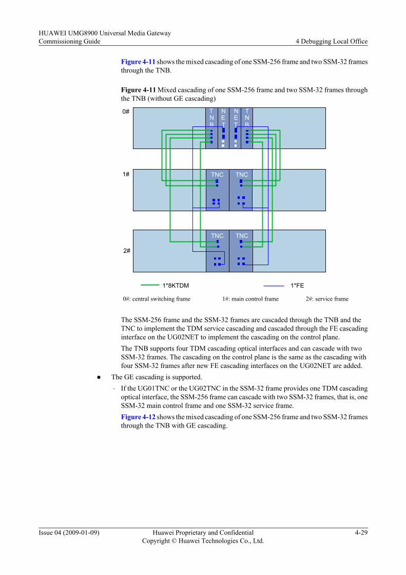
Figure 4-11 shows the mixed cascading of one SSM-256 frame and two SSM-32 framesthrough the TNB.
Figure 4-11 Mixed cascading of one SSM-256 frame and two SSM-32 frames throughthe TNB (without GE cascading)
TNC TNC
TNC TNC1#
1*8KTDM 1*FE
2#
0# TNB
TNB
NET
NET
0#: central switching frame 1#: main control frame 2#: service frame
The SSM-256 frame and the SSM-32 frames are cascaded through the TNB and theTNC to implement the TDM service cascading and cascaded through the FE cascadinginterface on the UG02NET to implement the cascading on the control plane.The TNB supports four TDM cascading optical interfaces and can cascade with twoSSM-32 frames. The cascading on the control plane is the same as the cascading withfour SSM-32 frames after new FE cascading interfaces on the UG02NET are added.
l The GE cascading is supported.– If the UG01TNC or the UG02TNC in the SSM-32 frame provides one TDM cascading
optical interface, the SSM-256 frame can cascade with two SSM-32 frames, that is, oneSSM-32 main control frame and one SSM-32 service frame.Figure 4-12 shows the mixed cascading of one SSM-256 frame and two SSM-32 framesthrough the TNB with GE cascading.
HUAWEI UMG8900 Universal Media GatewayCommissioning Guide 4 Debugging Local Office
Issue 04 (2009-01-09) Huawei Proprietary and ConfidentialCopyright © Huawei Technologies Co., Ltd.
4-29

Figure 4-12 Mixed cascading of one SSM-256 frame and two SSM-32 frames throughthe TNB (with GE cascading)
TNC TNC
TNC TNC
2#
1#
0# TNB
TNB
NET
NET
NLU
NLU
NLU
NLU
1*8KTDM 1*FE1*GE
0#: central switching frame 1#: main control frame 2#: service frame
In this mode, the GE cascading is supported, and one SSM-256 frame can be cascadedwith up to two SSM-32 frames. The cascading of the TDM service is implementedthrough the TNB and TNC, and the cascading of the control plane and packet plane isimplemented through the FE cascading interfaces and GE cascading interfaces on theUG02NET.
The TNB provides four TDM cascading optical interfaces, and two of them are cascadedwith two SSM-32 frames. The FE cascading interfaces on the UG02NET are cascadedwith FE3 interfaces on the TNCs in two SSM-32 frames through expansion.
In this mode, two GE interfaces on the UG02NET are cascaded with the opticalinterfaces of the NLUs in two SSM-32 frames to implement the cascading of the GEplane. The NLUs can be inserted in slots 4 and 5 or slots 10 and 11 in SSM-32 frames.In this manner, the NLUs can work only in the master and slave mode.
– If the UG02TNC in the SSM-32 frame provides two TDM cascading optical interfaces,the SSM-256 frame can cascade with two SSM-32 frames, that is, one SSM-32 maincontrol frame and one SSM-32 service frame.
On the TDM plane, the first SSM-32 frame, main control frame, connects to opticalinterfaces 0 and 1 on the BLU through TDM optical interfaces 0 and 1 on the UG02TNC.The second SSM-32 frame, service frame, connects to optical interfaces 2 and 3 on theBLU through TDM optical interfaces 0 and 1 on the UG02TNC. Refer to Figure4-11.
NOTE
The cascading on the FE and GE planes is the same as the cascading of two SSM-32 framesthrough the TNB.
4 Debugging Local OfficeHUAWEI UMG8900 Universal Media Gateway
Commissioning Guide
4-30 Huawei Proprietary and ConfidentialCopyright © Huawei Technologies Co., Ltd.
Issue 04 (2009-01-09)

BLU Usedl The GE cascading is not supported.
– If the UG01TNC or the UG02TNC in the SSM-32 frame provides one TDM cascadingoptical interface, the SSM-256 frame can cascade with four SSM-32 frames, that is, oneSSM-32 main control frame and three SSM-32 service frames.The SSM-256 central switching frame can cascade with the SSM-32 frame through theUG02BLU.C. If the GE cascading is not supported, the SSM-256 central switchingframe can cascade with four SSM-32 frames through the BLU. Refer to Figure 4-13.
Figure 4-13 Mixed cascading of one SSM-256 frame and four SSM-32 frames through the BLU(without GE cascading)
TNC TNC
TNC TNC
TNC TNC1#
1*8KTDM 1*FE
2#
3#
0# TNB
TNB
NET
NET
TNC TNC4#
BLUBLU
0#: central switching frame 1#: main control frame 2# to 4#: service frames
HUAWEI UMG8900 Universal Media GatewayCommissioning Guide 4 Debugging Local Office
Issue 04 (2009-01-09) Huawei Proprietary and ConfidentialCopyright © Huawei Technologies Co., Ltd.
4-31

In this mode, the SSM-256 frame and SSM-32 frames are cascaded through the BLUand TNC to implement the TDM cascading; they are cascaded through the FE interfaceson the BLUs to implement the FE cascading.
The BLU provides four TDM cascading optical interfaces, and they can be cascadedwith four SSM-32 frames. The FE cascading interfaces on the UG02BLU.C arecascaded with FE3 interfaces on the TNCs in four SSM-32 frames through expansion.
– If the UG02TNC in the SSM-32 frame provides two TDM cascading optical interfaces,the SSM-256 frame can cascade with two SSM-32 frames, that is, one SSM-32 maincontrol frame and one SSM-32 service frame.
On the TDM plane, the first SSM-32 frame, main control frame, connects to opticalinterfaces 0 and 1 on the BLU through TDM optical interfaces 0 and 1 on the UG02TNC.The second SSM-32 frame, service frame, connects to optical interfaces 2 and 3 on theBLU through TDM optical interfaces 0 and 1 on the UG02TNC. Refer to Figure4-11.
l The GE cascading is supported.
– If the UG01TNC or the UG02TNC in the SSM-32 frame provides one TDM cascadingoptical interface, the SSM-256 frame can cascade with two SSM-32 frames, that is, oneSSM-32 main control frame and one SSM-32 service frame.
If the UG02BLU.C is configured in the SSM-256 frame and the GE cascading issupported, the SSM-256 frame can cascaed with two SSM-32 frames through theUG02BLU.C. Refer to Figure 4-14.
Figure 4-14 Mixed cascading of one SSM-256 frame and two SSM-32 frames throughthe BLU (with GE cascading)
1*GE 1*FE1*8KTDM
TNC TNC
TNC TNC1#
2#
0# TNB
TNB
NET
NET
BLUBLU
NLU
NLU
NLU
NLU
0#: central switching frame 1#: main control frame 2#: service frame
4 Debugging Local OfficeHUAWEI UMG8900 Universal Media Gateway
Commissioning Guide
4-32 Huawei Proprietary and ConfidentialCopyright © Huawei Technologies Co., Ltd.
Issue 04 (2009-01-09)
In this mode, the GE cascading is supported, and one SSM-256 frame can be cascadedwith up to two SSM-32 frames. The cascading of the TDM service is implementedthrough the BLU and TNC, and the cascading of the control plane and packet plane isimplemented through the FE cascading interfaces and GE cascading interfaces on theBLU.
The BLU provides four TDM cascading optical interfaces, and two of them are cascadedwith two SSM-32 frames. The FE cascading interfaces on the BLU are cascaded withFE3 interfaces on the TNCs in two SSM-32 frames through expansion.
In this mode, two GE interfaces on the BLU are cascaded with the optical interfaces ofthe NLUs in two SSM-32 frames to implement the cascading of the GE plane. TheNLUs can be inserted in slots 4 and 5 or slots 10 and 11 in SSM-32 frames. In thismanner, the NLUs can work only in the master and slave mode.
The UG02NET and the BLU.C support the original configuration mode, and they canreplace the UG01NET and BLU.A.
– If the UG02TNC in the SSM-32 frame provides two TDM cascading optical interfaces,the SSM-256 frame can cascade with two SSM-32 frames, that is, one SSM-32 maincontrol frame and one SSM-32 service frame.
On the TDM plane, the first SSM-32 frame, main control frame, connects to opticalinterfaces 0 and 1 on the BLU through TDM optical interfaces 0 and 1 on the UG02TNC.The second SSM-32 frame, service frame, connects to optical interfaces 2 and 3 on theBLU through TDM optical interfaces 0 and 1 on the UG02TNC.
NOTE
The cascading on the FE and GE planes is the same as the cascading of two SSM-32 framesthrough the BLU.
4.4.5 Process of Cascading SwitchoverThis describes the process of cascading switchover.
If the cascading interfaces in two cascaded frames are not in the same status, the UMG8900synchronizes the status of the two interfaces through the master/slave switchover. The followingtakes the UG01BLU or the UG02BLU.A as an example. The master/slave status of the BLU isbased on the master/slave status of the cascading interface on the cascaded TNB/TNC/NET.After a BLU starts up, if the master/slave status of the BLU is not the same with that of thecascading part in the TNB/TNC/NET, the BLU is automatically switched to the status of theTNB/TNC/NET through the resetting if the switchover flag is on. The switchover principles ofthe UG02BLU.C are the same as those of the NET. Refer to the switchover process of the NET.
NOTE
The cascading switchover flag of the UMG8900 can automatically turn on or off based on the current status.If the cascading interfaces on the BLU are connected with optical fibers and are connected with the TNUproperly, the cascading switchover flag turns on automatically; otherwise, the cascading switchover flagturns off automatically.
The following takes the UG01BLU or the UG02BLU.A as an example. Any of the followingconditions can cause the BLU to be reset and switched between the master and slave status.
l The master/slave status of the cascading part in the TNB/TNC in a cascaded frame isinconsistent with that of the BLU in the central switching frame.
l The master/slave state of the cascading part in the NET in a cascaded frame is inconsistentwith that of the BLU in the central switching frame.
HUAWEI UMG8900 Universal Media GatewayCommissioning Guide 4 Debugging Local Office
Issue 04 (2009-01-09) Huawei Proprietary and ConfidentialCopyright © Huawei Technologies Co., Ltd.
4-33

l The cascading optical fiber is pulled out of the cascading optical interface on the masterBLU.
l The BLU is switched between the master and slave status or is reset through DevicePanel on the local maintenance terminal (LMT).
l The TNB/TNC/NET in a cascaded frame is switched between the master and slave statusor is reset.
Table 4-18 lists the influence of the switchover of cascading boards or cascading modules onthe other boards.
Table 4-18 Influence of the cascading switchover
Board Switchover Type Switchover Influence
TNB Board switchover The cascading modules are switched over. Themaster and slave TNBs/TNCs in the cascaded frameare not switched over, but the related cascadingmodules are switched over.
Cascading moduleswitchover
The related boards are not switched over. The masterand slave TNBs/TNCs in the cascaded frame are notswitched over. The related cascading modules areswitched over, and the original slave cascadingchannel is switched to the master status.The master and slave BLUs in the central switchingframe are switched over, and the original slave BLUis switched to the master status.
NET Board switchover The related cascading modules are switched over.The NETs in the cascaded frame are not switchedover, but the cascading modules in the NETs areswitched.
Cascading moduleswitchover
The related boards are not switched over. Thecascaded NETs are not switched over. The relatedcascading modules are switched over, and theoriginal slave cascading channel is switched to themaster status.The master and slave BLU boards in the centralswitching frame are not switched over.
BLU Board and cascadingmodule integratedswitchover
When the master and slave BLUs are switched over,the cascading modules in the BLUs are switched overat the same time. The master and slave TNBs/TNCs/NETs in the cascaded frame are not switched over,but the related cascading modules are switched overbetween the master and slave status.
4 Debugging Local OfficeHUAWEI UMG8900 Universal Media Gateway
Commissioning Guide
4-34 Huawei Proprietary and ConfidentialCopyright © Huawei Technologies Co., Ltd.
Issue 04 (2009-01-09)
Board Switchover Type Switchover Influence
TNC Board switchover The related cascading modules are switched over.The cascaded TNBs/TNCs are not switched over, butthe cascading modules are switched over.The master and slave BLUs in the central switchingframe are switched over, and the original slave BLUis switched to the master status.
Cascading moduleswitchover
The related boards are not switched over. Thecascaded TNBs/TNCs are not switched over. Therelated cascading modules are switched over, and theoriginal slave cascading channel is switched to themaster status.The master and slave BLUs in the central switchingframe are switched over, and the original slave BLUis switched to the master status.
4.4.6 Checking Cascading Cable ConnectionThis describes how to check the cable connection of the SSM-32 and SSM-256 self-cascadingand mixed cascading.
Procedure
Check whether the physical connection of the cascading system is correct.
Check whether the physical connection is correct according to the specifications in 4.4.1SSM-256 Self-Cascading, 4.4.2 SSM-32 Self-Cascading, 4.4.3 SSM-256 and SSM-32 MixedCascading (UG01NET and BLU.A Configured), and 4.4.4 SSM-256 and SSM-32 MixedCascading (UG02NET and BLU.C Configured).
----End
4.4.7 Checking Cascading Configurations and States of CascadingBoards
This describes how to check cascading configurations and states of cascading boards.
Procedure
Step 1 Check whether the LINK indicator on the cascading optical port is on.l If the LINK indicator on the cascading optical port is off, check whether the receiving and
sending ends of optical fibers are connected reversely and the optical fibers are of poorquality.
l If the LINK indicator of the cascading network cable is off, replace the network cable.
Step 2 When you configure a frame with ADD FRM, ensure that Cascading Board No. is the sameas the board No. of the connected BLU.
HUAWEI UMG8900 Universal Media GatewayCommissioning Guide 4 Debugging Local Office
Issue 04 (2009-01-09) Huawei Proprietary and ConfidentialCopyright © Huawei Technologies Co., Ltd.
4-35
Step 3 When a frame is added with ADD FRM, ensure that TDM CascadePort0 is the same as theNo. of the physically connected optical port.
In SSM-32 self-cascading mode, TDM CascadePort0 must be the same as the No. of the opticalport on the TNC in the main control frame that the service frame connects to.
In SSM-256 and SSM-32 mixed cascading mode, TDM CascadePort0 must be the same as theNo. of the optical port on the TNB/BLU in the central switching frame that the service frameconnects to.
Step 4 Check whether the running state of the cascading board is normal.
The boards related to the cascading include the TNU, BLU, FLU, and NET.
----End
4.4.8 Debugging FE CascadingThis describes how to debug fast Ethernet (FE) interface cascading.
ContextThe FE plane is used to transmit the operation and maintenance messages and the gateway controlmessages inside the UMG8900. The gateway control messages specify the service controlmessages related to H.248.
If the FE plane fails, the operation and maintenance function fails, and call loss of services occurson the UMG8900.
If the FE plane fails, the following may occur:
l ALM_0026 Cascading network interface failure occurs.
l ALM_0037 Board control network interface failure occurs.
l ALM_0052 The standby panel communication fault occurs.
l ALM_0040 Board fault occurs or the whole frame fails when the OMU, MPU, or TNC isinserted or pulled out.
l The whole frame fails when one cascading network cable between frames is pulled out.
l ALM_0055 Lanswitch report too much error packet occurs.
NOTE
l The internal control plane LAN Switch in the SSM-32 frame is located on the TNC. Pull out and insert,or power off each MTNC.
l The operation methods and commands of detecting the FE plane in the SSM-32 frame are the same asthose in the SSM-256 frame, but the operated board in the SSM-32 frame is the TNC.
ProcedureStep 1 Check whether ALM_0052 The standby panel communication fault occurs in the alarm
management system.l If yes, handle the alarm as follows:
Log in to the OMUs in slots 7 and 8 through the serial port or debug tool. Run mntlstfelinkinfo to check the states of the ports on the OMUs.– If the displayed state of one OMU is Link, and that of the other OMU is NotLink, it
indicates that the component of the network port on the OMU fails or the pins are badly
4 Debugging Local OfficeHUAWEI UMG8900 Universal Media Gateway
Commissioning Guide
4-36 Huawei Proprietary and ConfidentialCopyright © Huawei Technologies Co., Ltd.
Issue 04 (2009-01-09)
contacted. Pull out and insert the OMU. If the displayed state is still NotLink, replace theOMU.
– If the displayed state of the two OMUs is link, contact Huawei Technical Support forhelp.
l If not, perform Step 2.
Step 2 Log in to the alarm management system, and check whether ALM_3233 Packet loss rate reachedthreshold occurs and whether packet loss occurs on the external network ports providing networkcables on the NET. The network ports include the OMC port, MIR port, FE0 port, and FE1 port.
If the preceding problems occur, perform the following steps:
1. Check whether the work mode of the port is FULL_100 M. If not, modify it to FULL_100M. Then, observe whether the alarm still occurs.
2. If the alarm of packet loss or packet error still occurs when the work mode is FULL_100M, the network cable may be of poor quality. Replace the network cable, and then observewhether the alarm still occurs.
3. If the problem persists after the peer setting problem and the problem of the network cablequality are ruled out, contact Huawei Technical Support for help.
----End
4.4.9 Debugging TDM CascadingThis describes how to debug the time division multiplexing (TDM) interface cascading.
Context
CAUTIONBefore debugging the TDM plane, make sure that the clock system is normal.
The TDM plane is used to carry all the TDM related services, including the TDM trunk access,signaling transfer, and various types of semi-permanent connection services.
When the TDM plane in the frame fails,
l If the master TDM plane fails, the system resets the related faulty ports to recover the masterTDM plane and does not switch to the slave TDM plane.
l If the master TDM plane fails, services are interrupted.
When the TDM plane between frames fails,
l If the master TDM cascading plane between frames fails, the system automatically switchesto the slave TDM cascading plane between frames.
l If the master and slave TDM cascading planes between frames fail, the TDM services insidethe cascading frames and the TDM services across the cascading frames are all interrupted.
ProcedureStep 1 Debug TDM channels in each frame. The dialing test covers all the interface boards in each
frame. With the co-work of the softswitch, specify a trunk on each TDM interface board to make
HUAWEI UMG8900 Universal Media GatewayCommissioning Guide 4 Debugging Local Office
Issue 04 (2009-01-09) Huawei Proprietary and ConfidentialCopyright © Huawei Technologies Co., Ltd.
4-37
dialing tests. If the call is normal and the voice quality is good, it indicates that the master TDMplane is normal.
When the dialing test is made on a trunk, if one-way audio or no audio occurs to any other users,or all the signaling links on the board are disconnected or intermittently disconnected, performthe following step:
Run SWP BRD to switch over the master and slave TNUs in the frame.
l If the preceding faults are cleared, it indicates that the faults are caused by the master TNUin the frame before the switchover. Replace the related board.
l Otherwise, it indicates that the interface board is abnormal, and you must replace the interfaceboard.
Step 2 Debug TDM channels between frames.
Choose a frame, specify a trunk as the calling service trunk, and choose the trunks in other serviceframes as the called trunks in turn. With the co-work of the softswitch, make dialing tests on thespecified trunk. If the call is normal and the voice quality is good, it indicates that the masterTDM plane is normal.
Specify a trunk in each of the other frames as the calling service trunk, and choose the trunks inthe rest frames as the called trunks. With the co-work of the softswitch, make dialing tests onthe specified trunk.
For example, four frames provide TDM services, and they are respectively frame A, frame B,frame C, and frame D. Specify the trunk in frame A as the calling service trunk, and those inframe B, frame C, and frame D as the called service trunks. When the dialing test is complete,specify the trunk in frame B as the calling service trunk, and those in frame C and frame D asthe called service trunks. At last, specify the trunk in frame C as the calling service trunk, andthat in frame D as the called service trunk. The dialing test covers all the frames.
When a specified trunk in a frame is used to make dialing test for other frames, if one-way audioor no audio occurs, or all the signaling links across frames are disconnected or intermittentlydisconnected, perform the following steps:
1. Replace the related TNU, TCLU, TNB, and TNC in the service frame.2. Replace cascading optical fibers.3. Replace the TNU in the central switching frame to locate the fault.
Step 3 Switch over the master and slave TNUs in each frame, and repeat Step 1. If the call is normaland the voice quality is good, it indicates that the slave TDM plane in each frame is normal.
Step 4 Switch over the master and slave TNUs in each frame, and repeat Step 2. If the call is normaland the voice quality is good, it indicates that the slave channels between frames are normal.
----End
4.4.10 Debugging GE CascadingThis describes how to debug the gigabit Ethernet (GE) interface cascading.
ContextThe GE plane is used to carry packet services, and the related boards are ASU, HRB, VPU, NET,OMB, MPB, BLU, and FLU.
4 Debugging Local OfficeHUAWEI UMG8900 Universal Media Gateway
Commissioning Guide
4-38 Huawei Proprietary and ConfidentialCopyright © Huawei Technologies Co., Ltd.
Issue 04 (2009-01-09)
In the SSM-256 frame, the GE switching chip is located on the NET. In the SSM-32 frame, theGE switching chip is located on the OMB/MPB.
If the master GE plane fails, ALM_1606 GE channel fault occurs. According to the reasons forthe GE plane failure, the system switches over the boards related to the GE plane to eliminatethe effect on the services.
The system does not debug the slave GE plane. Even if the slave GE plane fails, no alarm occurs,and services are not affected temporarily; great hidden trouble, however, exists. If the masterGE plane fails at a certain time, services are interrupted, and a fault occurs.
Therefore, the system detects the slave GE plane, which includes the detection between framesand the detection in frames.
The detection between frames is classified as follows:
l Direct connection and cascading between SSM-265 frames
l Direct connection and cascading between the SSM-256 frame and the SSM-32 frame
The system periodically switches over the GE planes to detect the GE planes between frames.The slave plane is switched over to the master plane, and then is detected in the same way asthat the master plane is detected.
By inlooping the PHY port on the GE LAN Switch of the slave switch board, the chip is detectedbased on the received and sent packages of each port.
In multiframe cascading mode, GE cascading may not exist between some frames. Therefore,analyze the GE cascading between frames, and know about the frames related to GE cascading.The subsequent debugging is for the GE-related boards in the frames.
The multiframe GE cascading debugging ensures that the GE channels between two GE-relatedboards are normal when two GE planes exist.
The purpose of debugging the GE cascading is to:
l Ensure that the GE boards in frames can communicate on the two planes.
l Ensure that the GE boards between two frames related to the GE cascading cancommunicate on the two planes.
ProcedureStep 1 Run SWP BRD to switch over the NET or the MPB in the frames related to the GE cascading.
Make the boards in slots 7 of all frames the master boards, and the BLUs in the slots with thesmaller slot Nos. in all frames the master boards.
CAUTIONIf the NET is directly connected to the central switching frame and the NET in slot 7 of thedirectly connected frame is the master board, switch over the NETs to change the NET in slot8 to the master board, and then switch over them again to make the NET in slot 7 to the masterboard. Switching over the NETs twice ensures that the directly connected frame and the centralswitching frame can communicate through the optical fiber connecting to the NET in slot 7.
Step 2 Debug GE channels in each frame. Select a board related to the GE channel in the frame, suchas the HRB and the VPU, as the source board. Take other boards with the GE channels as the
HUAWEI UMG8900 Universal Media GatewayCommissioning Guide 4 Debugging Local Office
Issue 04 (2009-01-09) Huawei Proprietary and ConfidentialCopyright © Huawei Technologies Co., Ltd.
4-39
destination boards. Run LOP GE to debug GE channels in turn. The optional path includes theHRB-VPU.
For example, run the following command to debug the GE channels between the VPU in frontslot 2 of frame 1 and the HRB in slot 14:
LOP GE: SFN=1, SSN=2, SBP=FRONT, DFN=1, DSN=14, DBP=FRONT, TN=10;
l During the debugging with LOP GE, if a large number of GE channels are disconnected,the switching net board may fail. Replace the switching net board. For the SSM-256 frame,the switching net board is the NET; for the SSM-32 frame, the switching net board is theOMB/MPB.
l During the debugging with LOP GE, if the GE channels are disconnected or packet lossoccurs, the channels from the source board to the switching net boar or the channels fromthe switching net board to the source board may fail.
Suppose that A is the source board and B is the destination board. If the GE channels fromA to B are disconnected, run LOP GE on the channels from A to C and the channels fromB to C. If the channels from A to C are normal and the channels from B to C are abnormal,it indicates that the channels from B to the switching net board fail.
When the channels from B to the GE switching net board are disconnected, the reasons maybe:
– Failure of the service board
– Failure of the GE switching net board
– Failure of the cabling on the backplane between the service board and GE switching netboard
In this case, replace the boards and slots to locate the fault, and then replace the components.
Step 3 Debug GE channels between frames. Choose a pair of HRBs or VPUs in a frame related to thecascading as the source boards, and a HRB or VPU in other frames with the GE cascading asthe destination board. Run LOP GE to debug the channels in turn.
l During the debugging with LOP GE, if a large number of GE channels are disconnected,the switching net board may fail. Replace the switching net board. For the SSM-256 frame,the switching net board is the NET; for the SSM-32 frame, the switching net board is theOMB/MPB.
l During the debugging with LOP GE, if the GE channels are disconnected or packet lossoccurs, the channels from the source board to the switching net boar or the channels fromthe destination board to the switching net board may fail.
Suppose that A is the source board and B is the destination board. If the GE channels fromA to B are disconnected, run LOP GE on the channels from A to C and the channels fromB to C. If the channels from A to C are normal and the channels from B to C are abnormal,it indicates that the channels from B to the switching net board fail.
When the channels from B to the GE switching net board are disconnected, the reasons maybe:
– Failure of the service board
– Failure of the GE switching net board
– Failure of the cabling on the backplane between the service board and GE switching netboard
In this case, replace the boards and slots to locate the fault, and then replace the components.
4 Debugging Local OfficeHUAWEI UMG8900 Universal Media Gateway
Commissioning Guide
4-40 Huawei Proprietary and ConfidentialCopyright © Huawei Technologies Co., Ltd.
Issue 04 (2009-01-09)
CAUTIONThe GE channels between boards in different frames tested by LOP GE go in the followingdirection:
GE service board -> NET/MPB in the service frame -> GE cascading board -> NET in the centralswitching frame -> GE cascading board -> NET in the service frame -> GE service board.
In the two tests of the master and slave planes in the frame, do not change the source board, orthe destination board.
Step 4 Switch over the master and slave states of the cascading switching net boards. Run SWPBRD to switch over the GE cascading net boards in the frames related to the GE cascading.Change the boards in slots 8 of all the frames to the master boards, and the BLUs in the slotswith the bigger slot Nos. in all the frames to the master boards.
Repeat Step 2 and Step 3.
TIP
If the GE channels between the NETs/MPBs of two frames are disconnected or packet loss occurs, locatethe fault by testing whether the GE channels between the two frames and between the two frames and athird frame are connected. Perform the following steps:
l Make a loopback test on the boards between frames A and B. If the GE channels between frames Aand B are disconnected, test the GE channels from frame A to frame C and from frame B to frame C.If the GE channels from frame B to frame C are normal, it indicates that the fault locates between frameA and the central switching frame.
l Replace the optical fiber, GE cascading board, NET or MPB switching net board, and backplane inorder until all the faults are cleared.
----End
4.5 Debugging Service ResourcesThis describes how to debug service resources including transcoder (TC), echo cancellation(EC), interworking function (IWF), and multiparty service (MPTY).
Context
Here describes how to debug the resources of the UMG8900, including TC, EC, IWF, andMPTY. The resources are static, and thus debugging is performed by means of call setup. It isrecommended to debug every VPU and ECU.
4.5.1 Debugging TC ResourcesThis describes how to debug the transcoder (TC) resources.
4.5.2 Debugging EC ResourcesThis describes how to debug the echo cancellation (EC) resources.
4.5.3 Debugging MPTY ResourcesThis describes how to debug the multiparty service (MPTY) resources.
4.5.4 Debugging IWF ResourcesThis describes how to debug the interworking function (IWF) resources.
HUAWEI UMG8900 Universal Media GatewayCommissioning Guide 4 Debugging Local Office
Issue 04 (2009-01-09) Huawei Proprietary and ConfidentialCopyright © Huawei Technologies Co., Ltd.
4-41
4.5.1 Debugging TC ResourcesThis describes how to debug the transcoder (TC) resources.
ContextTC is transcoder resources. When two terminations used for communication have no commonvoice codec format, the TC resources are used to convert voice codecs.
The most direct and effective way for TC debugging is to establish a call that needs TC resources.If the call is established, it indicates that the UMG8900 has TC resources and can use them.Otherwise, check the configurations step by step.
Procedure
Step 1 Check whether the TC resource subboard is configured on the VPU.
The VPU has three slots for subboards, which are numbered 0, 1 and 2 from the top to the bottomrespectively. Slots 0 and 1 can hold only TC subboard, and slot 2 can hold either TC subboardor EC subboard.
Step 2 Check the total number of TC resources and their occupation information.
Run DSP MEDIARES, set the resource type to TC, and then you can view the statisticsinformation of TC channels. The following information is displayed: the total number of TCresources, total number of failed TC resources, and TC occupation information.
Step 3 Check the configurations of the codec capability on the VPU.
Run LST CODECCAP to check whether the codec capability set on the VPU supports the codecrequired by the call.
For details on the codec capability sets, see SET CODECCAP.
Step 4 Establish a call that needs TC resources. Make dialing test through IP trunks.
Step 5 Adjust work parameters of TC resources.
If the poor quality of voice or fax results from the network congestion, run SET TCPARA tochange TC work parameters such as encapsulation interval and dynamic jitter buffer. It isrecommended to adjust the work parameters of TC resources under the guidance of Huaweiengineers.
----End
4.5.2 Debugging EC ResourcesThis describes how to debug the echo cancellation (EC) resources.
ContextThe EC resources are used to cancel echoes.
The most direct and effective way for EC debugging is to set up a call that needs EC resourcesand check if echo accompanies the call. A good-quality call with no echo indicates that ECresources are provided by the UMG8900 and can be used.
4 Debugging Local OfficeHUAWEI UMG8900 Universal Media Gateway
Commissioning Guide
4-42 Huawei Proprietary and ConfidentialCopyright © Huawei Technologies Co., Ltd.
Issue 04 (2009-01-09)
Procedure
Step 1 Establish a call that does not need EC resources. When configuring MGC data, you do not addthe EC resource. Make dialing tests and check the voice quality. This step is to compare thequality of the call with that of the call using EC resources.
Step 2 Check whether the EC resource subboard is configured on the VPU and ECU. The VPU hasthree slots to hold subboards. Slot 2 can hold the EC subboard, and the two slots of the ECU canboth hold EC subboards.
Step 3 Check the total number of EC resources. Run DSP MEDIARES, set the resource type to EC,and then you can view the statistics information of EC channels. The following information isdisplayed: total number of EC resources and total number of failed TC resources.
Step 4 Establish a call that uses EC resources. When configuring media gateway controller (MGC)data, add EC resources. Make dialing tests and check the voice quality. A good-quality call withno echo indicates that EC resources are configured on the UMG8900 and can be used. Then,debugging EC resources is complete.
Step 5 Adjust work parameters of EC resources. If the loud echo persists when EC resources are used,run SET ECPARA to modify EC work parameters such as tail length. It is recommended toadjust the work parameters of EC resources under the guidance of Huawei engineers.
----End
4.5.3 Debugging MPTY ResourcesThis describes how to debug the multiparty service (MPTY) resources.
ContextThe UMG8900 provides MPTY resources, that is, audio mixing resources, to support callservices of multiple parties. The most direct and effective way for MPTY debugging is toestablish multiparty service calls. The participating parties include fixed-line phones andwireless user terminals. If the voice in the calls is clear, it indicates that the UMG8900 has theMPTY resources and can use them. Otherwise, check the configurations of the MPTY resources.
Procedure
Step 1 Establish a multiparty service call that needs MPTY resources. Join the conference and checkthe voice quality.l If the voice quality is good, it indicates that the MPTY resources are configured on the
UMG8900 and can be used properly, and thus you do not need to perform other debuggingoperations.
l Otherwise, perform Step 2.
Step 2 Run DSP MEDIARES, set the resource type to MPTY, and you can view the statisticsinformation of MPTY channels.
The following information is displayed: the total number of MPTY channels and the total numberof failed MPTY resources.
l If the total number of MPTY channels is 0, perform Step 3.
l Otherwise, perform Step 4.
HUAWEI UMG8900 Universal Media GatewayCommissioning Guide 4 Debugging Local Office
Issue 04 (2009-01-09) Huawei Proprietary and ConfidentialCopyright © Huawei Technologies Co., Ltd.
4-43
Step 3 Check whether the MPTY resource subboard is configured on the VPU.
The VPU has three slots for subboards, and the slots are numbered 0, 1, and 2 from the top tothe bottom. Slots 0 and 1 can hold 1,024 channels, and slot 2 can hold 2,048 channels.
NOTE
The hardware of the MPTY resource subboard and TC resource subboard is the MVDB subboard. MPTYresources can be configured on the MVDB only when it is in slot 2.
Step 4 Run LST CODECCAP to check the number of MPTY channels on the VPU.
----End
4.5.4 Debugging IWF ResourcesThis describes how to debug the interworking function (IWF) resources.
ContextThe most direct and efficient way for IWF debugging is to use a PC connected to an MS to sendfax to the public switched telephone network (PSTN). If the fax quality is good, it indicates thatthe UMG8900 can use IWF resources. Otherwise, check the configurations of IWF resources.
Procedure
Step 1 Send a fax that needs IWF resources. That is, send a fax from a mobile station (MS) to the PSTNor from the PSTN to an MS.l If the fax quality is good, it indicates the IWF resources are configured on the UMG8900
and can be used properly, and then perform Step 3.l Otherwise, perform Step 2.
Step 2 Check the physical connection between the UMG8900 and the shared interworking function(SIWF) and check whether the LINK indicator of FE0 interface on the NET is on.
NOTE
FE0 interface on the NET of the UMG8900 is connected with the FE interface on the SIWC of the SIWFto implement the interworking of the control plane.
Step 3 Run DSP SIWFSTAT to check whether the SIWF is registered. If not, run ACT SIWFFUN toactivate the IWF.
Step 4 Run LST TDMIU to check whether the type of the TDM trunk connecting with the SIWF isinside.
Step 5 Run LST IWFE1 to display E1 No. The E1 No. must be consistent with the E1 No. specifiedby ADD E1 on the SIWF side.
----End
4 Debugging Local OfficeHUAWEI UMG8900 Universal Media Gateway
Commissioning Guide
4-44 Huawei Proprietary and ConfidentialCopyright © Huawei Technologies Co., Ltd.
Issue 04 (2009-01-09)
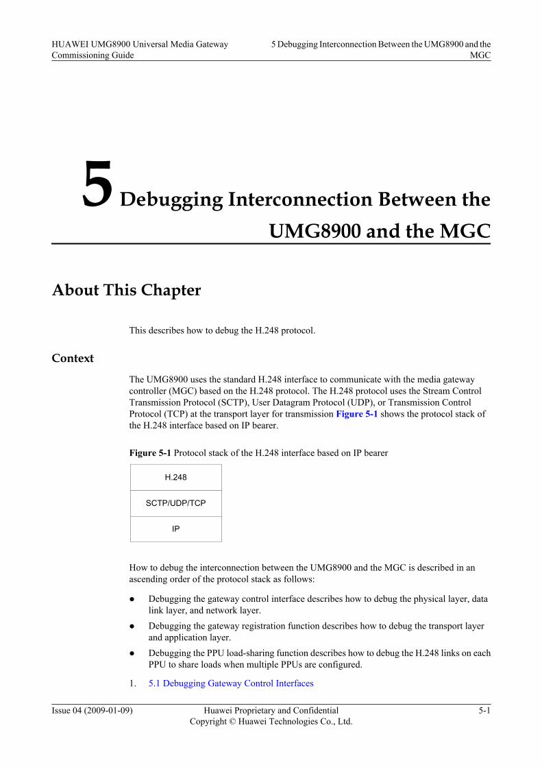
5 Debugging Interconnection Between theUMG8900 and the MGC
About This Chapter
This describes how to debug the H.248 protocol.
Context
The UMG8900 uses the standard H.248 interface to communicate with the media gatewaycontroller (MGC) based on the H.248 protocol. The H.248 protocol uses the Stream ControlTransmission Protocol (SCTP), User Datagram Protocol (UDP), or Transmission ControlProtocol (TCP) at the transport layer for transmission Figure 5-1 shows the protocol stack ofthe H.248 interface based on IP bearer.
Figure 5-1 Protocol stack of the H.248 interface based on IP bearer
H.248
SCTP/UDP/TCP
IP
How to debug the interconnection between the UMG8900 and the MGC is described in anascending order of the protocol stack as follows:
l Debugging the gateway control interface describes how to debug the physical layer, datalink layer, and network layer.
l Debugging the gateway registration function describes how to debug the transport layerand application layer.
l Debugging the PPU load-sharing function describes how to debug the H.248 links on eachPPU to share loads when multiple PPUs are configured.
1. 5.1 Debugging Gateway Control Interfaces
HUAWEI UMG8900 Universal Media GatewayCommissioning Guide
5 Debugging Interconnection Between the UMG8900 and theMGC
Issue 04 (2009-01-09) Huawei Proprietary and ConfidentialCopyright © Huawei Technologies Co., Ltd.
5-1
This describes how to debug the gateway control interface on the physical layer, data linkdata, and network layer.
2. 5.2 Debugging Gateway Registration FunctionThis describes how to check whether the UMG8900 registers with the media gatewaycontroller (MGC).
3. 5.3 Debugging PPU Load SharingThis describes how to debug the load sharing of the PPUs.
5 Debugging Interconnection Between the UMG8900 and theMGC
HUAWEI UMG8900 Universal Media GatewayCommissioning Guide
5-2 Huawei Proprietary and ConfidentialCopyright © Huawei Technologies Co., Ltd.
Issue 04 (2009-01-09)
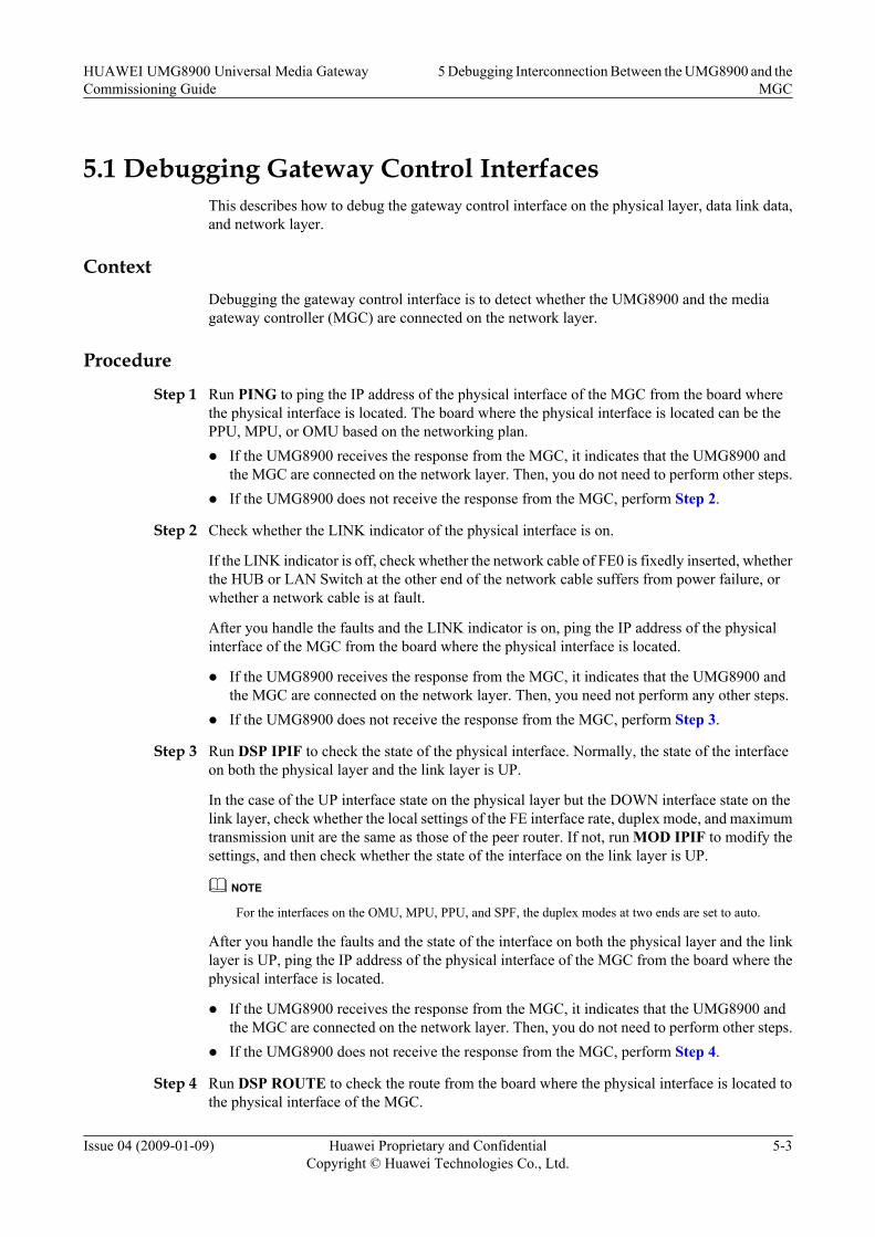
5.1 Debugging Gateway Control InterfacesThis describes how to debug the gateway control interface on the physical layer, data link data,and network layer.
ContextDebugging the gateway control interface is to detect whether the UMG8900 and the mediagateway controller (MGC) are connected on the network layer.
Procedure
Step 1 Run PING to ping the IP address of the physical interface of the MGC from the board wherethe physical interface is located. The board where the physical interface is located can be thePPU, MPU, or OMU based on the networking plan.l If the UMG8900 receives the response from the MGC, it indicates that the UMG8900 and
the MGC are connected on the network layer. Then, you do not need to perform other steps.l If the UMG8900 does not receive the response from the MGC, perform Step 2.
Step 2 Check whether the LINK indicator of the physical interface is on.
If the LINK indicator is off, check whether the network cable of FE0 is fixedly inserted, whetherthe HUB or LAN Switch at the other end of the network cable suffers from power failure, orwhether a network cable is at fault.
After you handle the faults and the LINK indicator is on, ping the IP address of the physicalinterface of the MGC from the board where the physical interface is located.
l If the UMG8900 receives the response from the MGC, it indicates that the UMG8900 andthe MGC are connected on the network layer. Then, you need not perform any other steps.
l If the UMG8900 does not receive the response from the MGC, perform Step 3.
Step 3 Run DSP IPIF to check the state of the physical interface. Normally, the state of the interfaceon both the physical layer and the link layer is UP.
In the case of the UP interface state on the physical layer but the DOWN interface state on thelink layer, check whether the local settings of the FE interface rate, duplex mode, and maximumtransmission unit are the same as those of the peer router. If not, run MOD IPIF to modify thesettings, and then check whether the state of the interface on the link layer is UP.
NOTE
For the interfaces on the OMU, MPU, PPU, and SPF, the duplex modes at two ends are set to auto.
After you handle the faults and the state of the interface on both the physical layer and the linklayer is UP, ping the IP address of the physical interface of the MGC from the board where thephysical interface is located.
l If the UMG8900 receives the response from the MGC, it indicates that the UMG8900 andthe MGC are connected on the network layer. Then, you do not need to perform other steps.
l If the UMG8900 does not receive the response from the MGC, perform Step 4.
Step 4 Run DSP ROUTE to check the route from the board where the physical interface is located tothe physical interface of the MGC.
HUAWEI UMG8900 Universal Media GatewayCommissioning Guide
5 Debugging Interconnection Between the UMG8900 and theMGC
Issue 04 (2009-01-09) Huawei Proprietary and ConfidentialCopyright © Huawei Technologies Co., Ltd.
5-3

Configure the route. After you confirm that the route information is correct, ping the IP addressof the physical interface of the MGC from the board where the physical interface is located.
l If the UMG8900 receives the response from the MGC, it indicates that the UMG8900 andthe MGC are connected on the network layer. Then, you need not perform other steps.
l If the UMG8900 does not receive the response from the MGC, perform Step 5.
Step 5 Check the access control list (ACL) rules of the firewall on the board where the interface tocheck is located. Check whether the ACL rules causing disconnection is configured on the routebetween the board and the interconnected interface.
Disable the firewall and then make ping tests.
----End
PostrequisiteAfter debugging the gateway control interface, debug the gateway registration function.
5.2 Debugging Gateway Registration FunctionThis describes how to check whether the UMG8900 registers with the media gateway controller(MGC).
Context
Debugging the gateway registration function is to debug whether the UMG8900 registers withthe MGC.
Procedure
Step 1 Run DSP VMGW to check whether the VMGW state is ACTIVE.
l If yes, it indicates that the UMG8900 registers with the MGC. Then, you do not need toperform other steps.
l If not, it indicates that the UMG8900 fails to register with the MGC. Perform Step 2.
Step 2 Run ACT VMGW to activate the UMG8900 to initiate the registration with the MGC.
Then, run DSP VMGW to check whether the VMGW state is ACTIVE.
l If yes, it indicates that the UMG8900 registers with the MGC. Then, you do not need toperform other steps.
l If not, it indicates that the UMG8900 fails to register with the MGC. Perform Step 3.
Step 3 Run DSP H248LNK to check whether the link state is UP.
l If the H.248 link state is UP, it indicates that the link is established on the transport layer,and then perform Step 6.
l If the H.248 link state is DOWN, it indicates that the link is not established on the transportlayer.
Fill in Table 5-1 based on the output result of DSP H248LNK.
5 Debugging Interconnection Between the UMG8900 and theMGC
HUAWEI UMG8900 Universal Media GatewayCommissioning Guide
5-4 Huawei Proprietary and ConfidentialCopyright © Huawei Technologies Co., Ltd.
Issue 04 (2009-01-09)

Table 5-1 H.248 link information
H.248 LinkNo.
Local IPAddress
Local PortNo.
Peer IPAddress
Peer PortNo.
TransportProtocolType
Step 4 Compare the data in Table 5-1 with that on the MGC side. Check whether the data is consistent.
If the local IP address and local port No. of the UMG8900 are the same as the destination IPaddress and destination port No. of the MGC and the destination IP address and destination portNo. of the UMG8900 are the same as the local IP address and local port No. of the MGC, performStep 5.
If any data is inconsistent, modify the related configurations of the UMG8900. Then, run DSPVMGW to check whether the UMG8900 registers with the MGC.
l If yes, it indicates that the UMG8900 registers with the MGC. Then, you do not need toperform other steps.
l If not, it indicates that the UMG8900 fails to register with the MGC. Perform Step 5.
Step 5 Run LST SCTPINIT to check whether the SCTP protocol stack parameters on the PPU areconsistent with those on the MGC side.
Check whether the check algorithms on the UMG8900 and MGC sides are the same, that is,CRC32 or ADLER32. If not, the SCTP link establishment fails.
CAUTIONAfter modifying the SCTP attributes, make sure to restart the module where the PPU board islocated, and then the modified parameters can take effect.
If the check algorithms on the UMG8900 and MGC sides are inconsistent, modify the relatedconfigurations. Then, run DSP VMGW to check whether the state of the current VMGW isACTIVE.
l If yes, it indicates that the UMG8900 registers with the MGC. Then, you do not need toperform other steps.
l If not, it indicates that the UMG8900 fails to register with the MGC. Perform Step 6.
Step 6 Run LST H248PARA, and fill in Table 5-2 based on the output result.
Table 5-2 H.248 parameter information
H.248 Codec Type Authentication Type Authentication Key
Compare the data in Table 5-2 with that on the MGC side. Check whether the data is consistent.
HUAWEI UMG8900 Universal Media GatewayCommissioning Guide
5 Debugging Interconnection Between the UMG8900 and theMGC
Issue 04 (2009-01-09) Huawei Proprietary and ConfidentialCopyright © Huawei Technologies Co., Ltd.
5-5

If the data is inconsistent, modify the related configurations. Then, run DSP VMGW to checkwhether the VMGW state is ACTIVE.
l If yes, it indicates that the UMG8900 registers with the MGC. Then, you do not need toperform other steps.
l If not, it indicates that the UMG8900 fails to register with the MGC. Perform Step 7.
Step 7 Run LST VMGW to check whether the VMGW ID is consistent with that on the MGC side.
If not, modify the related parameters.
----End
PostrequisiteAfter debugging the gateway registration function, debug the load sharing of the PPU.
5.3 Debugging PPU Load SharingThis describes how to debug the load sharing of the PPUs.
ContextIn actual networking applications, usually multiple PPUs are configured on the UMG8900 toarchive load sharing of the H.248 control packets with the media gateway controller (MGC).You must debug the PPU load sharing during the deployment.
Procedure
Step 1 Run LST H248LNK to check whether H.248 links are reasonably planned.
Check whether H.248 links are planned on each physical board that is equipped with the PPUmodule.
Step 2 Debug the H.248 links board by board. When debugging the H.248 links of a board equippedwith the PPU module, you must remove the other boards equipped with the PPU modules.RunDEA VMGW and then ACT VMGW.
After running ACT VMGW, run DSP VMGW to check whether the VMGW state is ACTIVE.
l If yes, it indicates that the virtual media gateway (VMGW) can use the H.248 links on thePPU to complete registration with the MGC. Make dialing tests. If the call is connected, itindicates that load sharing between the PPUs is enabled.
l If not, see 5.2 Debugging Gateway Registration Function.
----End
5 Debugging Interconnection Between the UMG8900 and theMGC
HUAWEI UMG8900 Universal Media GatewayCommissioning Guide
5-6 Huawei Proprietary and ConfidentialCopyright © Huawei Technologies Co., Ltd.
Issue 04 (2009-01-09)
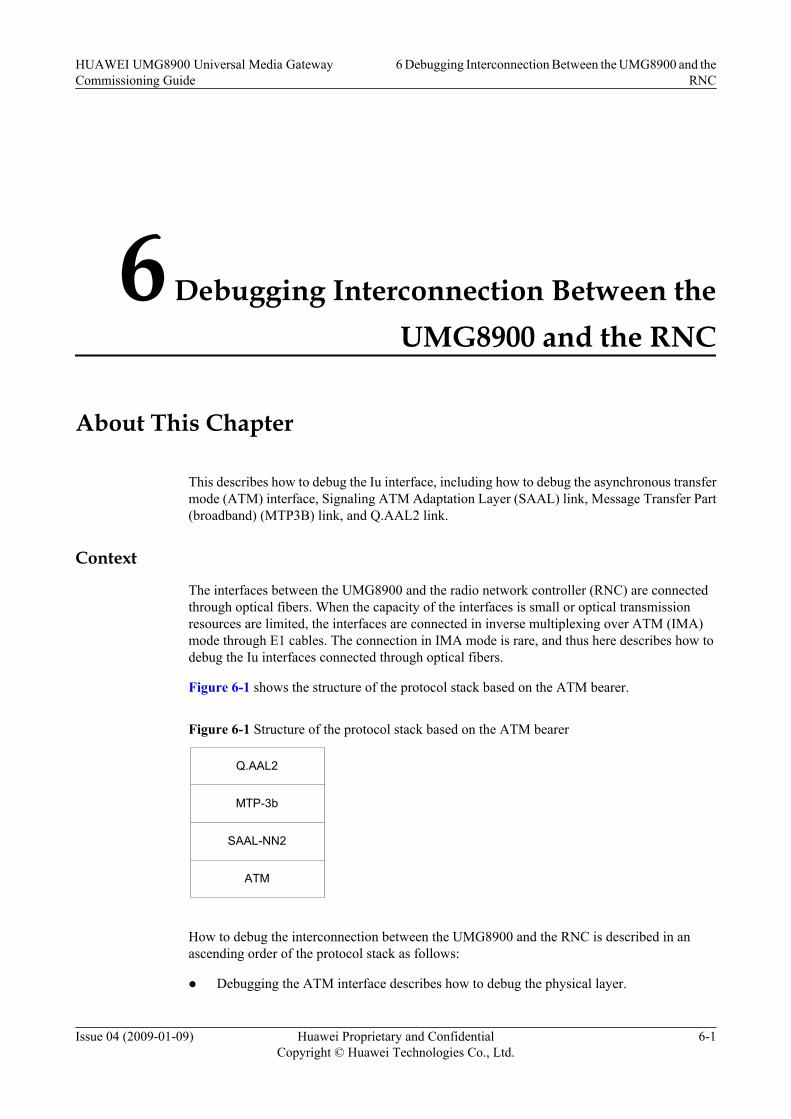
6 Debugging Interconnection Between theUMG8900 and the RNC
About This Chapter
This describes how to debug the Iu interface, including how to debug the asynchronous transfermode (ATM) interface, Signaling ATM Adaptation Layer (SAAL) link, Message Transfer Part(broadband) (MTP3B) link, and Q.AAL2 link.
Context
The interfaces between the UMG8900 and the radio network controller (RNC) are connectedthrough optical fibers. When the capacity of the interfaces is small or optical transmissionresources are limited, the interfaces are connected in inverse multiplexing over ATM (IMA)mode through E1 cables. The connection in IMA mode is rare, and thus here describes how todebug the Iu interfaces connected through optical fibers.
Figure 6-1 shows the structure of the protocol stack based on the ATM bearer.
Figure 6-1 Structure of the protocol stack based on the ATM bearer
MTP-3b
SAAL-NN2
ATM
Q.AAL2
How to debug the interconnection between the UMG8900 and the RNC is described in anascending order of the protocol stack as follows:
l Debugging the ATM interface describes how to debug the physical layer.
HUAWEI UMG8900 Universal Media GatewayCommissioning Guide
6 Debugging Interconnection Between the UMG8900 and theRNC
Issue 04 (2009-01-09) Huawei Proprietary and ConfidentialCopyright © Huawei Technologies Co., Ltd.
6-1
l Debugging the SAAL link describes how to debug the SAAL link by creating the SAALinterface trace.
l Debugging the MTP3B link describes how to debug the MTP3B link by creating theMTP3B interface trace.
l Debugging the Q.AAL2 link describes how to debug the Q.AAL2 link by initiating callson the RNC side and creating the Q.AAL2 interface trace.
For ATM bearer, the local interface parameters must be consistent with the peer ones. On thispremise, you can debug interfaces by observing board indicators, querying alarms and signalingpoint status, and starting tracing functions.
1. 6.1 Debugging ATM InterfacesThis describes how to debug the asynchronous transfer mode (ATM) interface on thephysical layer.
2. 6.2 Debugging SAAL LinksThis describes how to debug the Signaling ATM Adaptation Layer (SAAL) link.
3. 6.3 Debugging MTP3B LinksThis describes how to debug the Message Transfer Part(broadband) (MTP3B) link.
4. 6.4 Debugging Q.AAL2 LinksThis describes how to debug the Q.AAL2 link.
6 Debugging Interconnection Between the UMG8900 and theRNC
HUAWEI UMG8900 Universal Media GatewayCommissioning Guide
6-2 Huawei Proprietary and ConfidentialCopyright © Huawei Technologies Co., Ltd.
Issue 04 (2009-01-09)
6.1 Debugging ATM InterfacesThis describes how to debug the asynchronous transfer mode (ATM) interface on the physicallayer.
Procedure
Step 1 Check the LINK indicator of the optical interface on the back board of the ASU is normal (green).
l If the LINK indicator is on, it indicates that the physical connection is normal. Then performStep 5.
l If the LINK indicator is off, it indicates that the physical connection fails. Then perform Step2.
Step 2 On the optical distribution frame (ODF), use the ring flange to make a loopback test on theUMG8900. Check whether the LINK indicator is on.
NOTEIt is recommended to loop back the peer radio network controller (RNC) on the ODF, tell the peer operatorto check whether the peer synchronous digital hierarchy (SDH) interface indicator is normal, and checkwhether the transmission between the ODF and the peer RNC is normal.
l If the LINK indicator is still off during the loopback test, replace the optical fiber or theboard. Cancel the loopback after handling the related fault. Then, check whether the LINKindicator is on.
– If yes, perform Step 5.
– If not, make the loopback test again. If the LINK indicator is on after the loopback test,perform Step 3.
l If the LINK indicator is on during the loopback test but is off after loopback cancellation,perform Step 3.
Step 3 Check whether the receiving and sending ends of optical fibers are connected reversely.Exchange the receiving and sending ends of optical fibers of the local optical interface, andcheck whether the LINK indicator is on.
l If yes, perform Step 5.
l If not, perform Step 4.
Step 4 Run LST OPTINFO to check the information of the optical module.
Check whether the optical fiber matches the optical module, and whether the optical module ofthe RNC matches that of the A4L.
Step 5 Run LST SDHFLAG to check the overhead configuration of the local ATM optical interfaceand whether the overhead byte is consistent with that of the peer RNC.
Step 6 Run DSP PORTSTS to check the detailed information of the ATM optical interface and whetherthe existing error bit counts constantly increase.
If the error bit counts exist, the optical fiber may fail or the optical components of the ATMinterface fails.
----End
HUAWEI UMG8900 Universal Media GatewayCommissioning Guide
6 Debugging Interconnection Between the UMG8900 and theRNC
Issue 04 (2009-01-09) Huawei Proprietary and ConfidentialCopyright © Huawei Technologies Co., Ltd.
6-3

PostrequisiteAfter debugging the ATM interface, debug the Signaling ATM Adaptation Layer (SAAL) link.
6.2 Debugging SAAL LinksThis describes how to debug the Signaling ATM Adaptation Layer (SAAL) link.
Procedure
Step 1 Run DSP SAALLNK to check whether SSCOPState and SSCFState are Data TransferReady and whether LinkStatus is Connected.
l If LinkStatus is Connected, you need not perform other steps.
l If LinkStatus is Disconnected, perform Step 2.
Step 2 Create an SAAL interface trace task.
l If you can view the related message, perform Step 4.
NOTEDuring link establishment and upper-layer data transfer, the message is SD. If the link is normal, themaintenance message is POLL and STAT exchanged. The messages are updated quickly.
l If you cannot view the related message, perform Step 3.
Step 3 Check whether the permanent virtual channels (PVCs) on the UMG8900 and the radio networkcontroller (RNC) are connected. If yes, view the related message. After you view the relatedmessage, run DSP SAALLNK to check whether SSCOPState and SSCFState are DataTransfer Ready and whether LinkStatus is Connected.
l If LinkStatus is Connected, you need not perform other steps.
l If LinkStatus is Disconnected, perform Step 4.
Step 4 Run DSP MTP3BLNK to check whether the state of the link is available.
l If not, modify the related configurations. Then, run DSP SAALLNK to check whetherSSCOPState and SSCFState are Data Transfer Ready and whether LinkStatus isConnected.
l If yes, perform Step 5.
Step 5 If no SAAL link is configured on the RNC, you can loop back the UMG8900 on the opticaldistribution frame (ODF), and check the SAAL link state. If the link is normal, you can determinethat the UMG8900 is normal. If not, check the optical interface and the optical fiber.
----End
PostrequisiteAfter debugging the SAAL link, debug the Message Transfer Part (broadband) (MTP3B) link.
6.3 Debugging MTP3B LinksThis describes how to debug the Message Transfer Part(broadband) (MTP3B) link.
6 Debugging Interconnection Between the UMG8900 and theRNC
HUAWEI UMG8900 Universal Media GatewayCommissioning Guide
6-4 Huawei Proprietary and ConfidentialCopyright © Huawei Technologies Co., Ltd.
Issue 04 (2009-01-09)
Procedure
Step 1 Run DSP MTP3BLNK to check whether the running state of the MTP3B is available. Run DSPMTP3BDPC to check whether the destination signaling point (DSP) corresponding to the radionetwork controller (RNC) is available. If yes, debugging the MTP3B link is complete.
Step 2 Start the MTP3B interface trace. Check whether messages are sent and received and whetherthe received messages (especially OPC, DPC, and SLC) are correct to determine whether theconfigurations on the UMG8900 and the RNC are correct. If the link is normal, the maintenancemessage is SLTM and SLTA exchanged. The messages are updated slowly.
Step 3 Check the configured data, especially whether the originating signaling point (OSP), DSP, andlink code are consistent with those of the RNC.
----End
PostrequisiteAfter debugging the MTP3B link, debug the Q.AAL2 link.
6.4 Debugging Q.AAL2 LinksThis describes how to debug the Q.AAL2 link.
Procedure
Step 1 Run DSP QAAL2ADJNODE to check whether the Q.AAL2 adjacent node is normal.
l If yes, perform Step 2.
l If not, see 6.2 Debugging SAAL Links and 6.3 Debugging MTP3B Links to check the dataof the lower three layers (MTP3B, SAAL, and PVC). After the fault is cleared, perform Step2.
Step 2 Make a call on the radio network controller (RNC) side, and check whether the bearer channelcan be established. Create a Q.AAL2 interface trace task on the UMG8900 to check the tracingmessages.
l Among the tracing messages, if the UMG8900 receives the ERQ message from the RNC butdoes not return the acknowledgement, it indicates that the AAL2 path used by the RNC duringthe call is not configured on the UMG8900. Run DSP AAL2PATH to check whether thelocal path ID is consistent with that of the RNC and whether the numbers of paths are thesame. If not, modify the related parameters.
l Among the tracing messages, if the UMG8900 receives the ERQ message from the RNC andreturns the RLC message, it indicates that no ATM resource is configured on the VMGW.Run LST AAL2VMGW to check whether the number of the virtual media gateway(VMGW) subscribers corresponding to the calls is configured. If the number is 0, modify itto the expected value.
l Normally, the UMG8900 receives the ERQ message from the RNC and returns the ECFacknowledgement message.
----End
HUAWEI UMG8900 Universal Media GatewayCommissioning Guide
6 Debugging Interconnection Between the UMG8900 and theRNC
Issue 04 (2009-01-09) Huawei Proprietary and ConfidentialCopyright © Huawei Technologies Co., Ltd.
6-5

7 Debugging Interconnection Between theUMG8900 and the BSC/MSC/PSTN Switch
About This Chapter
This describes how to debug the E1/T1, E3/T3, and synchronous digital hierarchy (SDH)interface.
ContextThe UMG8900 is connected with the base station controller (BSC)/mobile switching center(MSC)/ public switched telephone network (PSTN) switch over time division multiplexing(TDM). The debugging includes the E1/SDH interface debugging and the service dialing test.Here describes the interface debugging, including:
7.1 Making E1/T1 Self-Loopback TestsThis describes how to make the E1/T1 self-loopback test.
7.2 Debugging E1/T1 LinksThis describes how to debug the E1/T1 links.
7.3 Debugging E3/T3 PortsThis describes how to debug the E3/T3 ports.
7.4 Debugging SDH InterfacesThis describes how to debug the synchronous digital hierarchy (SDH) interfaces.
7.5 Debugging SDH Interface ProtectionThis describes how to debug the synchronous digital hierarchy (SDH) interface protection.
HUAWEI UMG8900 Universal Media GatewayCommissioning Guide
7 Debugging Interconnection Between the UMG8900 and theBSC/MSC/PSTN Switch
Issue 04 (2009-01-09) Huawei Proprietary and ConfidentialCopyright © Huawei Technologies Co., Ltd.
7-1

7.1 Making E1/T1 Self-Loopback TestsThis describes how to make the E1/T1 self-loopback test.
ContextAfter installing hardware, check whether the local E1/T1 cables are connected and whether theE1/T1 ports are normal before debugging software. The check can be performed by making theE1/T1 self-loopback test.
ProcedureStep 1 Pull all E1/T1 connectors of an E32/T32 out of the digital distribution frame (DDF).
Step 2 Connect the receiving end and the sending end of the E1/T1 cables and make the local loopbacktest.
Step 3 Run DSP E1PORT to display the state of the ports on one E32/T32.
The displayed state of the E1/T1 ports is OK. If the state of the E1/T1 ports is Fault or DISABLE,check whether the E1/T1 cables are loosely inserted in the DDF or the E1/T1 connector is poorlywelded. Make new E1/T1 connectors if necessary.
Step 4 If the E1/T1 cables are well connected, the E1/T1 ports may have problems. Then, run LOPE1 to make the software loopback (the loopback mode is set to inloop) to check whether thestate of the E1/T1 ports is OK.
This loopback is made on the ports or chips through software, and it is not related to the physicalconnections. If the state of the E1/T1 ports is still faulty, it indicates that the hardware of the E1/T1 port may be faulty.
Step 5 If the state of the E1/T1 ports is OK, the E1/T1 cables are well connected with the DDF, and theE1/T1 connectors are good, use the multimeter to check whether the resistance between thecopper sheet outside the E1/T1 connectors and the inside chip is normal. You can compare theresistance with the normal measured results of the E1/T1 connectors.
Step 6 When the state of the E1/T1 ports is OK, perform the preceding steps to make self-loopbacktests on and check the E1/T1 cables of other E32/T32 boards.
Step 7 After the test, restore normal connection of all connectors. Run LOP E1 to set LoopbackMode to Non-loopback to cancel all the local loopbacks.
NOTE
Run DSP E1LOP to check whether all the loopbacks are cancelled.
----End
7.2 Debugging E1/T1 LinksThis describes how to debug the E1/T1 links.
ContextWhen E1/T1 links are used to interconnect with the UMG8900 and other devices, check whetherthe E1/T1 transmission channels work before making dialing tests. If the transmission channels
7 Debugging Interconnection Between the UMG8900 and theBSC/MSC/PSTN Switch
HUAWEI UMG8900 Universal Media GatewayCommissioning Guide
7-2 Huawei Proprietary and ConfidentialCopyright © Huawei Technologies Co., Ltd.
Issue 04 (2009-01-09)

fail (the displayed state of the ports is FAULT) or the calls have noise, the bit error rate of thetransmission channels is probably high. The commonly-used method is to make the loopbacktest and the bit error test. The steps are as follows: Connect the E1/T1 trunk with theinterconnected device (such as the public switched telephone network (PSTN) switch), makedialing tests on the media gateway controller (MGC) by using a specified trunk, make voiceservices carried on the E1/T1 trunk, and then check whether the calls can be established andwhether the voice quality is good.
Procedure
Step 1 According to 7.1 Making E1/T1 Self-Loopback Tests, check whether the links from the localdigital distribution frame (DDF) to the E1/T1 ports are normal.
When a problem arises, check whether the local links are normal. If yes, make the peer loopbacktest with the cooperation of the office site.
Step 2 Run LOP E1 to loop back the peer device by setting Loopback Mode to Remote. Notify thepeer side to check the state of the related peer E1/T1 ports. Alternatively, make the UMG8900loopback on the peer device and check the state of the related E1/T1 ports. The state of the E1/T1 ports shall be OK.
The software loopback is made to check whether the end-to-end E1/T1 transmission is normal.If yes, perform Step 4. If not, perform Step 3.
Step 3 Make the loopback test by segment to locate the faulty transmission segment. For example, makethe UMG8900 loopback test on the peer DDF and check whether the end-to-end transmissionis normal. If not, make the UMG8900 loopback test on the local DDF and locate the fault bysegment.
The hardware loopback is made to locate the transmission fault by segment.
Step 4 If the loopback test is normal but the state of the ports is FAULT after the loopback is cancelled,run DSP E1PORT to check whether the frame format and line codec format of the UMG8900are consistent with those of the interconnected device.
When the frame format and line codec format of the UMG8900 and the interconnected deviceare inconsistent, the state of the ports is FAULT.
Step 5 Run DSP SLIP to check the slips of the E1/T1 ports and the statistics information on slipsgenerated on the lines.
When the slips are of a large quantity, check the bit error rate and clock of the transmission lines.
Step 6 After the test, restore normal connection of all connectors. Run LOP E1 with LoopbackMode set to Non-loopback to cancel all the local loopbacks.
Run DSP E1LOP to check whether all the loopbacks are cancelled.
Step 7 Run CHK E1CROSS to check whether the E32/T32 has crossed pairs.
NOTE
When running CHK E1CROSS, set Loopback Mode of the peer device to Remote. Make sure that yourun DSP E1PORT to check that no loopback is occurring in the UMG8900.
If the state of the ports in the output results is OK, it indicates that the local port is normal. Ifthe output result is among 0 to 31, it indicates that the port receives the data of the specific portwith the output result. That is, the port and the port with the output result are in the cross-connected lines.
HUAWEI UMG8900 Universal Media GatewayCommissioning Guide
7 Debugging Interconnection Between the UMG8900 and theBSC/MSC/PSTN Switch
Issue 04 (2009-01-09) Huawei Proprietary and ConfidentialCopyright © Huawei Technologies Co., Ltd.
7-3

Step 8 Make dialing tests on the MGC by using a specified trunk with the voice services carried on it,and then check whether the calls can be established and whether the voice quality is good. Checkeach E1/T1 trunk by making dialing tests.
----End
7.3 Debugging E3/T3 PortsThis describes how to debug the E3/T3 ports.
Procedure
Step 1 Check whether the LINK indicator of the E3 interface is on.l If yes, you do not need to perform the following steps.
l If not, perform Step 2.
Step 2 Run DSP E3PORT to check whether the frame format and framing mode of the UMG8900 areconsistent with those of the peer device, whether the loopback is made on ports, and whetherthe alarm related to the port exists.
After handling the related fault, check whether the LINK indicator is on.
If not, perform Step 3.
Step 3 Check whether the sending and receiving ends of the cables are connected reversely.l If yes, correct the cable connection. Then, check whether the LINK indicator is on. If not,
perform Step 4.l If not, perform Step 4.
Step 4 Run LOP E3 to set Loopback Type to Local Loop, Location to LIU, and Mode to Local DigitLoopback.l If the LINK indicator is on, it indicates that the PIE is normal. In this case, run LOP E3 to
cancel the loopback. Then, perform Step 6.l If the LINK indicator is not on, it indicates that the PIE fails. Replace the PIE and then perform
Step 5.
Step 5 Run LOP E3 to cancel the loopback and then check whether the LINK indicator is on.l If yes, you do not need to perform the following steps.
l If not, perform Step 6.
Step 6 Run LOP E3. Set Loopback Type to FEAC Peer Loop, Location to E3/T3 Line, and Modeto Enable LoopBack.
NOTE
You can use FEAC peer loopback only when the used framing mode is C-bit Parity and the peer devicesupports FEAC peer loop.
If the LINK indicator is not on, it indicates that the peer device or cable is faulty. You can askthe peer end to make self loopback to check whether the peer board is abnormal.
Step 7 Run LOP E3 to set Loopback Type to FEAC Peer Loop, Location to E3/T3 Line, andMode to Disable Loopback.
----End
7 Debugging Interconnection Between the UMG8900 and theBSC/MSC/PSTN Switch
HUAWEI UMG8900 Universal Media GatewayCommissioning Guide
7-4 Huawei Proprietary and ConfidentialCopyright © Huawei Technologies Co., Ltd.
Issue 04 (2009-01-09)
7.4 Debugging SDH InterfacesThis describes how to debug the synchronous digital hierarchy (SDH) interfaces.
Procedure
Step 1 Check whether the LINK indicator of the SDH interface is on.
l If yes, perform Step 5.
l If not, perform Step 2.
Step 2 Perform the local loopback test with a flange on the optical distribution frame (ODF) and checkwhether the LINK indicator is on.
NOTEIt is recommended to loop back the peer device on the ODF at the same time, inform the peer end to checkwhether the indicator on the peer SDH interface is normal, and check whether the transmission betweenthe ODF and the peer device is normal.
l If the LINK indicator is on, it indicates that the optical fiber from the ODF to the local endis normal. Then perform Step 3.
l If the LINK indicator is off, replace the optical fiber or the board, and clear the related fault.Cancel the loopback and check whether the LINK indicator is on. If yes, perform Step 5. Ifnot, perform Step 3.
Step 3 If the LINK indicator is on during the loopback test but is off after the loopback is cancelled,the sending and receiving ends of the cables may be connected inversely. Cancel the loopback,exchange the sending and receiving ends of the local cables and check whether the LINKindicator is on.
l If yes, perform Step 5.
l If not, perform Step 4.
Step 4 Run DSP S2LPORT to check whether the frame type and frame format are consistent with thoseof the peer device.
Clear the related fault, and perform Step 5.
Step 5 Check whether the alarm related to the SDH interface exists in the alarm management system.According to the alarm information, check whether the SDH overhead bytes are consistent withthose of the peer device.
l If ALM_2613 Signal identifier of SDH higher order path mismatching,ALM_2614 SDHhigher order path not loaded,or ALM_2621 SDH lower order path not loaded occurs, runLST SDHFLAG to check whether the set C2 byte is consistent with that of the transmissiondevice.
l If occurs, run LST SDHFLAG to check whether the set J1 byte is consistent with that of thetransmission device.
l If ALM_2623 Trace identifier of SDH lower order path mismatching occurs, run LSTSDHFLAG to check whether the set J2 byte is consistent with that of the transmission device.
Step 6 Run SET PERMON to enable the performance monitoring function to check whether errorcodes exist in the transmission channels.
HUAWEI UMG8900 Universal Media GatewayCommissioning Guide
7 Debugging Interconnection Between the UMG8900 and theBSC/MSC/PSTN Switch
Issue 04 (2009-01-09) Huawei Proprietary and ConfidentialCopyright © Huawei Technologies Co., Ltd.
7-5
NOTE
Run SET PERTIME to set the start time for performance monitoring, and run DSP CSESEVT to displaythe consecutive severely errored second (SES) events.
----End
7.5 Debugging SDH Interface ProtectionThis describes how to debug the synchronous digital hierarchy (SDH) interface protection.
ContextNOTE
You must configure the 1+1 backup or 1:N backup of the SDH interface before performing the SDHinterface protection.
Procedure
Step 1 Run SET PG to start the protection group controller. Then, run DSP PGSTAT to check thestate of the protocol controller. Normally, the initial protocol controller is in the starting state.If you check the state of the protocol controller several seconds later, the controller is in the idlestate.
When the protocol controller is idle, the output frame No., slot No., and optical interface No.specify the position of the protection channel.
Step 2 Check whether the ACT indicator on the master optical interface (work channel) is always onand whether the ACT indicator on the slave optical interface (protection channel) is off.
NOTE
Make sure to check the master indicator (ACT) on the service interface. The ACT indicator on the serviceinterface is orange, and that on the board is green.
Step 3 Pull the optical fiber out of the master optical port, which causes the signal loss.
The ACT indicator on the original master optical interface (work channel) is off, and that on theoriginal slave optical interface (protection channel) is on.
Step 4 Insert the removed optical fiber. After the recovery time ends, check the traffic recovery.
The ACT indicator on the optical interface configured as the work channel is on and that of theoptical interface configured as the protection channel is off.
NOTE
You can do the recovery test only when Recover mode is set to Recover by using ADD PG; otherwise,skip this test.
Run SET WRTIME to set Recover time length(s) to 600.
Step 5 Check whether the protocol controller is normal with the preceding steps. If the switchoverbetween the channels fails, check whether the peer transmission device runs normally, whetherthe optical fiber or optical interface is normal, and whether the protection configuration of thelocal interface is correct.
7 Debugging Interconnection Between the UMG8900 and theBSC/MSC/PSTN Switch
HUAWEI UMG8900 Universal Media GatewayCommissioning Guide
7-6 Huawei Proprietary and ConfidentialCopyright © Huawei Technologies Co., Ltd.
Issue 04 (2009-01-09)

NOTE
The SDH interface protection requires the cooperation of the peer transmission device. If the channelswitchover is abnormal, first check whether the peer transmission device supports switchover protectionand runs normally.
Step 6 After the protocol controller runs normally, make dialing tests on the MGC by using a specifiedtrunk and make the call pass the work channel of the S2L. Pull out the optical fiber of the workchannel during the call, and check whether the call is disconnected during the channelswitchover.
----End
HUAWEI UMG8900 Universal Media GatewayCommissioning Guide
7 Debugging Interconnection Between the UMG8900 and theBSC/MSC/PSTN Switch
Issue 04 (2009-01-09) Huawei Proprietary and ConfidentialCopyright © Huawei Technologies Co., Ltd.
7-7

8 Debugging Interconnection Between theUMG8900 and Other MGWs/BSCs/RNCs
About This Chapter
This describes how to debug the IP interfaces and IP bearer.
1. 8.1 Debugging IP InterfacesThis describes how to debug the physical layer and link layer of the Ethernet interfaces.
2. 8.2 Debugging IP BearerThis describes how to debug the Internet Protocol (IP) bearer.
3. 8.3 Debugging IP Interface ProtectionThis describes how to debug the Internet Protocol (IP) interface protection.
4. 8.4 Debugging Route BackupThis describes how to debug the route backup.
HUAWEI UMG8900 Universal Media GatewayCommissioning Guide
8 Debugging Interconnection Between the UMG8900 andOther MGWs/BSCs/RNCs
Issue 04 (2009-01-09) Huawei Proprietary and ConfidentialCopyright © Huawei Technologies Co., Ltd.
8-1
8.1 Debugging IP InterfacesThis describes how to debug the physical layer and link layer of the Ethernet interfaces.
Context
Debugging the IP interfaces is to debug the FE/GE interfaces on the back interface board of theHRB to check whether the lower three layers of the IP interfaces are normal. The lower threelayers are the physical layer, data link layer, and network layer.
8.1.1 Debugging Ethernet InterfacesThis describes how to debug the physical layer and link layer of the Ethernet interfaces.
8.1.2 Debugging IPoE1 InterfacesThis describes how to debug the physical layer and link layer of the IPoE1 interface.
8.1.3 Debugging Network LayerThis describes how to debug the network layer of the Internet Protocol (IP) interface.
8.1.1 Debugging Ethernet InterfacesThis describes how to debug the physical layer and link layer of the Ethernet interfaces.
Procedure
Step 1 Check whether the LINK indicator on the fast Ethernet (FE)/gigabit Ethernet (GE) port is on. Ifthe LINK indicator is on, it indicates that the physical layer is connected.
If the LINK indicator is off, check whether the state of the boards is OK, whether the networkcables and optical fibers of the interfaces are well connected, whether the interconnected device(LAN Switch or router) is powered down, whether network cables fail, and whether the receivingand sending ends of the optical fibers are reversely connected (you can exchange the receivingand sending ends of the local optical fibers). If the loopback test can be made on the opticalfibers on the optical distribution frame (ODF), check whether the optical fiber has a problem,use an optical power meter to measure the optical power at the optical interface and the end ofthe connected optical fiber to check whether the sent and received optical power is normal andwhether the received optical power meets the requirement of the sensitivity.
NOTE
Normally, the LINK indicator on the FE interface is green. If the LINK indicator is always on, it indicatesthat the link is connected. The indicator of the FE interfaces on the ME8T is orange, and it is the LINKand ACT indicator. If the indicator is always on, it indicates that the link is connected. If the indicatorflashes, it indicates that data is received and sent.
Step 2 Check the state of the FE/GE interface.
Run DSP IPIF to check the state of the FE/GE interface. Normally, the state of the physicallayer and data link layer is UP. If the state of the physical layer is UP and that of the data linklayer is DOWN, check whether the configurations of the interface rate, duplex mode, andmaximum transmission unit (MTU) of the FE/GE interfaces are consistent with those of theinterconnected device. If not, run MOD IPIF to modify the configurations. The FE interfaceson the HRB are configured to be 100 M and full-duplex. The GE interfaces on the HRB must
8 Debugging Interconnection Between the UMG8900 andOther MGWs/BSCs/RNCs
HUAWEI UMG8900 Universal Media GatewayCommissioning Guide
8-2 Huawei Proprietary and ConfidentialCopyright © Huawei Technologies Co., Ltd.
Issue 04 (2009-01-09)
be configured to be 1000 M and full-duplex. If the previously mentioned requirements are notmet, packet loss may occur.
Step 3 (Optional) If the Trunking interfaces are configured, check whether the configurations of thelocal Trunking interfaces are correct and whether the convergence configurations of theinterconnected switch are consistent with those of the UMG8900.
Run DSP IPIF to check the state of the Trunking interfaces and all the FE interfaces in theTrunking interfaces. Normally, the state of the physical layer and link layer is UP. The state ofall the FE interfaces in the Trunking interfaces is normal.
Step 4 If the virtual local area network (VLAN) is configured, check whether the configurations of thelocal VLAN are correct and whether the VLAN configurations of the interconnected device(LAN Switch) and remote device (router or MGC) are correct.
Run LST IFVLAN to check whether VLAN ID in the output results is correct. If incorrect, runMOD IPIF to modify the configurations.
NOTE
l If the VLAN is configured on the local Ethernet interface, the interfaces of the LAN Switch connectedto the interface must be the Trunking interfaces.
l The VLAN ID of the local Ethernet interface must be consistent with that of the VLAN to which theports of the interconnected LAN Switch belong; otherwise, the interconnection fails.
l If the IP addresses bound with the VLAN and the IP addresses not bound with the VLAN are configuredon the local Ethernet interfaces, configure the interfaces of the interconnected LAN Switch to be in themixed mode.
----End
8.1.2 Debugging IPoE1 InterfacesThis describes how to debug the physical layer and link layer of the IPoE1 interface.
Procedure
Step 1 Debug the E1/T1/E3/T3/synchronous digital hierarchy (SDH) interfaces to ensure that thetransmission lines are connected. For detailed debugging steps, see 7 DebuggingInterconnection Between the UMG8900 and the BSC/MSC/PSTN Switch.
Step 2 Check whether the settings of the Serial interfaces are correct.l The time division multiplexing (TDM) timeslots on which the binding relationship is
configured must be the inside timeslots, and no other applications are configured on them.l Run LST BIND and LST CHANNEL to check whether the settings of the timeslots in the
Serial interface are correct.
Step 3 (Optional) If the Password Authentication Protocol (PAP) or Challenge HandshakeAuthentication Protocol (CHAP) authentication mode is used, check whether the Point-to-PointProtocol (PPP) authentication of the two sides is consistent.
Run LST PPPAUTH to check whether the authentication mode, user name, host name, andpassword of the UMG8900 are consistent with those of the interconnected router. Duringinterconnection, it is recommended to run MOD IPIF to set Authentication mode to NONE,and then check whether the two sides can be interconnected without authentication to see whetherthe disconnection of the link layer is related to the PPP authentication.
HUAWEI UMG8900 Universal Media GatewayCommissioning Guide
8 Debugging Interconnection Between the UMG8900 andOther MGWs/BSCs/RNCs
Issue 04 (2009-01-09) Huawei Proprietary and ConfidentialCopyright © Huawei Technologies Co., Ltd.
8-3

Step 4 (Optional) Check whether the settings of the VT interfaces are correct.
The maximum transmission units (MTUs) of the two Serial interfaces in one MP (that is, thetwo Serial interfaces are configured to one VT interface) must be the same, and the number ofthe accepted timeslots must be the same.
Step 5 Check the state of the IP interfaces.
Run DSP IPIF to check the state of the Serial and VT interfaces. The physical layer and linklayer must be UP. If the state of the physical layer is UP and that of the link layer is DOWN,check whether the PPP authentication is consistent with that of the interconnected router, andthe cyclic redundancy check (CRC) authentication and scramble settings are consistent withthose of the peer end. If not, run SET PPPAUTH to modify the settings of the PPP authenticationparameters.
----End
8.1.3 Debugging Network LayerThis describes how to debug the network layer of the Internet Protocol (IP) interface.
ContextDebugging the network layer is to check whether the UMG8900 can reach the remote mediagateway (MGW). The simplest debugging method is to run PING to ping the remote MGWfrom the board where the IP bearer interfaces are located. If the response can be received fromthe remote MGW, it indicates that the network layer is connected. If no response is receivedfrom the remote MGW, perform the following steps:
Procedure
Step 1 Check whether the MGW is valid.
Run DSP GWADDR to check whether the MGW is valid. If invalid, run LST GWADDR tocheck whether the gateway address is the same as the actual gateway address. If not, remove theMGW and then configure the MGW again.
Step 2 Check whether the IP address of the MGW is correctly parsed.
Run DSP ARP to check whether the address resolution item of the gateway exists in the AddressResolution Protocol (ARP) mapping table. The system can automatically resolve and refresh thecorresponding MAC address of the gateway only when the IP address of the gateway is valid.
Step 3 Check whether the network layer between the IP interface and the MGW is connected.
Run PING to ping the gateway IP address from the HRB. If the virtual local area network(VLAN) is configured, run PING for different VLANs to ensure the IP addresses in one VLANcan be reachable. The IP addresses in different VLANs cannot be reachable, and in this casedisconnect the router. Otherwise, after the IP packets are transferred through routers, the IPaddresses in different VLANs can be reachable.
Step 4 Check whether the remote MGW is reachable on the gateway connected to the local MGW.l Ping the gateway connected to the remote MGW on the gateway connected to the local MGW.
If ping succeeds, it indicates the bearer network is normal.l If ping fails, run TRACERT on the HRB to locate the IP network fault and clear it.
8 Debugging Interconnection Between the UMG8900 andOther MGWs/BSCs/RNCs
HUAWEI UMG8900 Universal Media GatewayCommissioning Guide
8-4 Huawei Proprietary and ConfidentialCopyright © Huawei Technologies Co., Ltd.
Issue 04 (2009-01-09)
Step 5 Check whether the network address transmission (NAT) or firewall exists in the network.
Check whether the NAT or firewall exists in the network through the network operator andwhether they are correctly configured.
----End
PostrequisiteAfter debugging the IP interfaces, debug the IP bearer.
8.2 Debugging IP BearerThis describes how to debug the Internet Protocol (IP) bearer.
ContextIP bearer is debugged based on the successfully debugged network layer. Thus, this introducesonly the following contents.
Procedure
Step 1 Check the domain ID.
Run LST DOMAIN to check whether the domain ID is correct. Observe whether A planestart address and A plane end address in the output results are consistent withthose planned.
Step 2 Check whether the bearer bandwidth is configured for the IP address.
Run LST IPIF to check whether the bearer bandwidth is configured for the IP address of theback board of the HRB.
NOTE
l The bearer bandwidth of the Serial interface cannot be more than the maximum bandwidth supportedby the interface. The maximum bandwidth of the interface is the number of the timeslots multipliedby 64 kbit/s.
l The bearer bandwidth of the VT interface cannot be more than the sum of the maximum bandwidthsupported by all the Serial interfaces, that is, the number of the timeslots supported by all the Serialinterfaces in the VT interface multiplied by 64 kbit/s.
Step 3 Check the bearer capability of the boards.Run LST BEARCAPA to check the bearer capability of the boards. If the bearer capability is0, it indicates that no bearer capability exists.
Step 4 Check the non-bearer reserved port No.
Run LST RSVPORT to check whether the non-bearer reserved port Nos. are correct. The non-bearer reserved ports are often used for the centralized forwarding, and they are reserved for thecontrol interfaces. Observe whether Start Port and End Port in the output results are thesame as those planned.
Step 5 Check the reserved IP termination ID.Run LST RSVIPTID to list the reserved IP termination ID configured. This command is usedonly when the UMG8900 is interconnected with the softswitch of other vendors and the
HUAWEI UMG8900 Universal Media GatewayCommissioning Guide
8 Debugging Interconnection Between the UMG8900 andOther MGWs/BSCs/RNCs
Issue 04 (2009-01-09) Huawei Proprietary and ConfidentialCopyright © Huawei Technologies Co., Ltd.
8-5
softswitch has restrictions on the IP termination ID allocated to the UMG8900. Check whetherthe value range of the reserved IP termination ID in the command execution result is the sameas the planned value range.
Step 6 Perform check by making dialing tests.
During dialing tests, if abnormality occurs, start the H.248 message trace and IP interface traceto observe the interaction of the message and then locate the fault.
----End
8.3 Debugging IP Interface ProtectionThis describes how to debug the Internet Protocol (IP) interface protection.
Context
In some networking applications, the UMG8900 must consider the reliability of local IPinterfaces. That is, when a fault occurs to the interface between the UMG8900 and a device suchas a router, the services can be switched from the faulty master interface to the slave interfacequickly.
For descriptions and configurations of the IP interface protection, see the HUAWEI UMG8900Universal Media Gateway Configuration GuideConfiguring IP Bearer.
Run PING to debug the IP interface protection.
Procedure
Step 1 When both the work channel and protection channel are normal, PING the interconnected routerfrom the HRB board and check the returned messages. At the same time, observe the ACTindicators on the IP interfaces. If an ACT indicator is flashing, it indicates that the correspondinginterface is used to send and receive the ping packets. Namely, this interface is in the workchannel.
NOTE
l For the MHRU, the fast Ethernet (FE) interface, and asynchronous transfer mode (ATM) interfaceautomatically support the 1+1 on-off protection (non 1+1 APS protection), ATM interface can support1+1 APS protection through the protection group configurations. The GE interface supports the 1+1on-off protection through the protection group configurations.
l When the orange indicator on the FE/GE interface flashes, it indicates that the links are receiving orsending data.
Step 2 PING the interconnected router from the HRB. During the PING operation, pull the networkcable or optical fiber out of the IP interface that is in the work channel. Observe whether thereis packet loss and the ACT indicators of the IP interfaces. If an ACT indicator is flashing, itindicates that the corresponding interface is used to send and receive the PING packets. Whenthe work channel fails, the interface in the protection channel should be used to send and receiveIP packets and there should be no packet loss.
Step 3 (Optional) Insert the network cable or optical fiber of the work channel again. PING theinterconnected router from the HRB. Observe the ACT indicators on the IP interfaces to checkwhether packet loss occurs.
8 Debugging Interconnection Between the UMG8900 andOther MGWs/BSCs/RNCs
HUAWEI UMG8900 Universal Media GatewayCommissioning Guide
8-6 Huawei Proprietary and ConfidentialCopyright © Huawei Technologies Co., Ltd.
Issue 04 (2009-01-09)
Make this test only when Recover mode is set to recover in ADD PG. Otherwise, skip this test.Recover mode can only be Not recover for the interface in a non-APS protection mode, and thusskip this test if the IP interface adopts a non-APS protection mode.
Step 4 Check whether the IP interface protection takes effect by performing the preceding three steps.If the switchover between the channels fails, check whether the interconnected router ortransmission device runs normally, whether the network cables, optical fibers, and interfaces arenormal, and whether the protection configurations of the local interface are correct.
Step 5 After PING succeeds, make dialing tests. During the call, pull out the optical fibers in the workchannel, and check whether the call is disconnected during the link switchover.
Step 6 For the ATM interface using the 1+1 APS or 1:N APS protection mode, pull the optical fibersout of the interface of the interconnected device, and repeat performing steps 3 to 5.
This step is used to test the bidirectional protection of the APS. Thus, if the IP interface uses thenon-APS protection mode, skip the step.
----End
8.4 Debugging Route BackupThis describes how to debug the route backup.
ProcedureStep 1 When the master and slave links are normal, ping the interconnected router on the HRB to check
whether the PING messages are returned.
Run DSP IPIF to check the sending and receiving of the packets on the master and slaveinterfaces.
NOTE
l For the HRU, only the gigabit Ethernet (GE) interface supports the route backup.
l Normally, the master Internet Protocol (IP) interface sends packets, and both the master and slave IPinterfaces can receive packets.
l For the HRD, both GE and fast Ethernet (FE) interfaces support the route backup.
Step 2 PING the interconnected router on the HRB. During this process, pull the optical fibers out ofthe IP interfaces of the master link, and observe whether packet loss occurs.
Run DSP IPIF to check the sending and receiving of the packets on the master and slaveinterfaces. When the master link fails, the slave link is used to receive and send packets and nopacket loss occurs.
Step 3 Insert the optical fiber of the master link again, and PING the interconnected router on the HRBto check whether the ping messages are returned.
Run DSP IPIF to check the sending and receiving of the packets on the master and slaveinterfaces. When the master link is recovered, the master interface can normally receive andsend packets.
Step 4 Check whether the route backup takes effect by performing the preceding three steps. If themaster and slave links cannot be normally switched over, check whether the configurations ofthe interconnected router are correct and whether the configurations of the local route backupare correct.
HUAWEI UMG8900 Universal Media GatewayCommissioning Guide
8 Debugging Interconnection Between the UMG8900 andOther MGWs/BSCs/RNCs
Issue 04 (2009-01-09) Huawei Proprietary and ConfidentialCopyright © Huawei Technologies Co., Ltd.
8-7

NOTE
l When the IP addresses of the master and slave interfaces are in different network segments, one routefrom the gateway interconnected to the slave interface to network segment of the master interface mustbe guaranteed.
l When the IP addresses of the master and slave interfaces are in the same network segment and differentLANs, ARP deal method must be set to Always.
Step 5 After PING succeeds, make dialing tests. During the call, pull the optical fibers out of the masterlink and check whether the call is disconnected during the link switchover.
----End
8 Debugging Interconnection Between the UMG8900 andOther MGWs/BSCs/RNCs
HUAWEI UMG8900 Universal Media GatewayCommissioning Guide
8-8 Huawei Proprietary and ConfidentialCopyright © Huawei Technologies Co., Ltd.
Issue 04 (2009-01-09)
9 Debugging Signaling Transfer
About This Chapter
This describes how to debug the SIGTRAN protocol and channel associated signaling (CAS).
ContextFor common channel signaling (CCS), the UMG8900 supports the embedded signaling gatewayfunction to implement the signaling adaptation and transfer. In different networks, theUMG8900 can adopt the following modes for signaling transfer:
l MTP2-M2UA signaling transfer
l MTP3-M3UA signaling transfer
l MTP3B-M3UA signaling transfer
l Q.921-IUA signaling transfer
l For the CAS of R2 and International No. 5 (No.5), the UMG8900 adapts the signaling toH.248 messages and then transfers them.
9.1 Debugging MTP2-M2UA Signaling LinksThis describes how to debug the MTP2-M2UA signaling links.
9.2 Debugging MTP3-M3UA Signaling LinksThis describes how to debug the MTP3-M3UA signaling links.
9.3 Debugging MTP3B-M3UA Signaling LinksThis describes how to debug the MTP3B-M3UA signaling links.
9.4 Debugging Q.921-IUA Signaling LinksThis describes how to debug the Q.921-IUA signaling links.
9.5 Debugging R2 Signaling TransferThis describes how to debug the R2 signaling.
HUAWEI UMG8900 Universal Media GatewayCommissioning Guide 9 Debugging Signaling Transfer
Issue 04 (2009-01-09) Huawei Proprietary and ConfidentialCopyright © Huawei Technologies Co., Ltd.
9-1

9.1 Debugging MTP2-M2UA Signaling LinksThis describes how to debug the MTP2-M2UA signaling links.
PrerequisiteBefore debugging the MTP2-M2UA links, complete the debugging of the E1 interfaces and E1links on the time division multiplexing (TDM) side and the debugging of the network layer onthe IP side. For how to debug interfaces, see 7.1 Making E1/T1 Self-Loopback Tests, 7.2Debugging E1/T1 Links, and 8.1 Debugging IP Interfaces.
ContextThe embedded SG of the UMG8900 uses the MTP2-M2UA mode to adapt and transfer the SS7,as shown in Figure 9-1.
Figure 9-1 Signaling adaptation and transfer in the MTP2-M2UA mode
SEP UMG8900 MGC
S7UP
MTP3
S7UP
MTP3
MTP2
MTP1 MTP1
MTP2M2UASCTP
IP
M2UASCTP
IPMAC MAC
SS7 IP
M2UA-NIF
TDM IP
M2UA: MTP2 User AdaptationLayer
MTP: Message Transfer Part SEP: signaling endpoint
S7UP: SS7 user part NIF: node interworking function MGC: media gateway controller
MAC: media access control SCTP: Stream Control TransmissionProtocol
Procedure
Step 1 Check the state of the M2UA links.
Run DSP L2UALNK to check the state of the MTP2 User Adaptation Layer (M2UA) linksbetween the UMG8900 and the MGC.
l Normally, the state of the M2UA links is ACTIVE.
l If the state of the M2UA links is UNESTABLISHED, perform Step 2.
l If the state of the M2UA links is INACTIVE, perform Step 3.
Step 2 Check the data configurations of the M2UA links.
9 Debugging Signaling TransferHUAWEI UMG8900 Universal Media Gateway
Commissioning Guide
9-2 Huawei Proprietary and ConfidentialCopyright © Huawei Technologies Co., Ltd.
Issue 04 (2009-01-09)

If the state of the M2UA links is UNESTABLISHED, it indicates that the Simple ControlTransfer Protocol SCTP links carrying M2UA are not established, and then perform thefollowing:
l Run LST L2UALNK to check whether Local IP Address, Local port No., Remote IPAddress, and Remote port No. of the M2UA links are consistent with those of the MGC.In addition, check whether the work mode of the M2UA links of the UMG8900 is Server,and that of the MGC is Client.
l Run LST SCTPINIT to check whether the checksum algorithm on the UMG8900 side isconsistent with that on the MGC side. The checksum algorithm on the two sides must beconsistent; otherwise, the SCTP links cannot be established.
CAUTIONAfter modifying the SCTP parameters, make sure to restart the SPF to validate the modifiedparameters.
Step 3 Create an M2UA interface trace task.
If the state of the M2UA links is INACTIVE, create an M2UA interface trace task on theUMG8900 to locate the fault by checking the tracing messages.
l Unsupported traffic handling modeAmong the tracing messages, if the UMG8900 receives AspActive messages from the MGCand returns Error messages indicating the unsupported traffic handling mode,it indicates that the traffic handling mode of the M2UA link sets of the UMG8900 isinconsistent with that of the MGC. Run RMV L2UALKS and ADD L2UALNK to set themode of the UMG8900 consistent with that of the MGC, which may be master/slave or loadsharing.
l Invalid interface identifierAmong the tracing messages, if the UMG8900 receives the AspActive message from theMGC and responses with ERROR indicating the wrong interface ID,it indicates that the interface ID of the MTP2 links of the UMG8900 is inconsistent with thatof the MGC. Run RMV MTP2LNK and ADD MTP2LNK to modify the interface ID ofthe MTP2 links of the UMG8900 consistent with that of the MGC.
l Returning ReleaseIndicationAmong the tracing messages, if the UMG8900 receives the EstablishReq message from theMGC and returns the ReleaseIndication message, it indicates that the MPT2 links are notestablished.Run LST MTP2LNK to check whether the MTP2 links of the UMG8900 and MGC occupythe same timeslot of an E1 cable, and whether the peer MTP2 links are correctly configured.Run DSP SPFSUBRD to check whether the SPF subboard processing the MTP2 links isabnormal.
l Receiving no EstablishRequestIf the UMG8900 does not receive any EstablishRequest message from the MGC, check therelated settings and state of the MGC.
l Unidirectional traced messages
HUAWEI UMG8900 Universal Media GatewayCommissioning Guide 9 Debugging Signaling Transfer
Issue 04 (2009-01-09) Huawei Proprietary and ConfidentialCopyright © Huawei Technologies Co., Ltd.
9-3
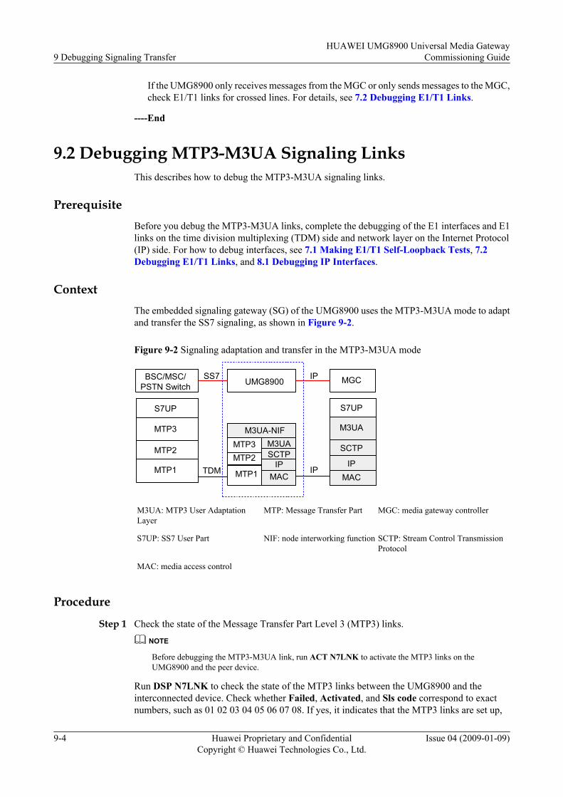
If the UMG8900 only receives messages from the MGC or only sends messages to the MGC,check E1/T1 links for crossed lines. For details, see 7.2 Debugging E1/T1 Links.
----End
9.2 Debugging MTP3-M3UA Signaling LinksThis describes how to debug the MTP3-M3UA signaling links.
PrerequisiteBefore you debug the MTP3-M3UA links, complete the debugging of the E1 interfaces and E1links on the time division multiplexing (TDM) side and network layer on the Internet Protocol(IP) side. For how to debug interfaces, see 7.1 Making E1/T1 Self-Loopback Tests, 7.2Debugging E1/T1 Links, and 8.1 Debugging IP Interfaces.
ContextThe embedded signaling gateway (SG) of the UMG8900 uses the MTP3-M3UA mode to adaptand transfer the SS7 signaling, as shown in Figure 9-2.
Figure 9-2 Signaling adaptation and transfer in the MTP3-M3UA mode
UMG8900 MGC
S7UP
MTP3
S7UP
MTP2
MTP1 MTP1
MTP3 M3UASCTP
IP
M3UA
SCTP
IPMAC MAC
SS7 IP
M3UA-NIF
TDM IPMTP2
BSC/MSC/PSTN Switch
M3UA: MTP3 User AdaptationLayer
MTP: Message Transfer Part MGC: media gateway controller
S7UP: SS7 User Part NIF: node interworking function SCTP: Stream Control TransmissionProtocol
MAC: media access control
Procedure
Step 1 Check the state of the Message Transfer Part Level 3 (MTP3) links.
NOTE
Before debugging the MTP3-M3UA link, run ACT N7LNK to activate the MTP3 links on theUMG8900 and the peer device.
Run DSP N7LNK to check the state of the MTP3 links between the UMG8900 and theinterconnected device. Check whether Failed, Activated, and Sls code correspond to exactnumbers, such as 01 02 03 04 05 06 07 08. If yes, it indicates that the MTP3 links are set up,
9 Debugging Signaling TransferHUAWEI UMG8900 Universal Media Gateway
Commissioning Guide
9-4 Huawei Proprietary and ConfidentialCopyright © Huawei Technologies Co., Ltd.
Issue 04 (2009-01-09)
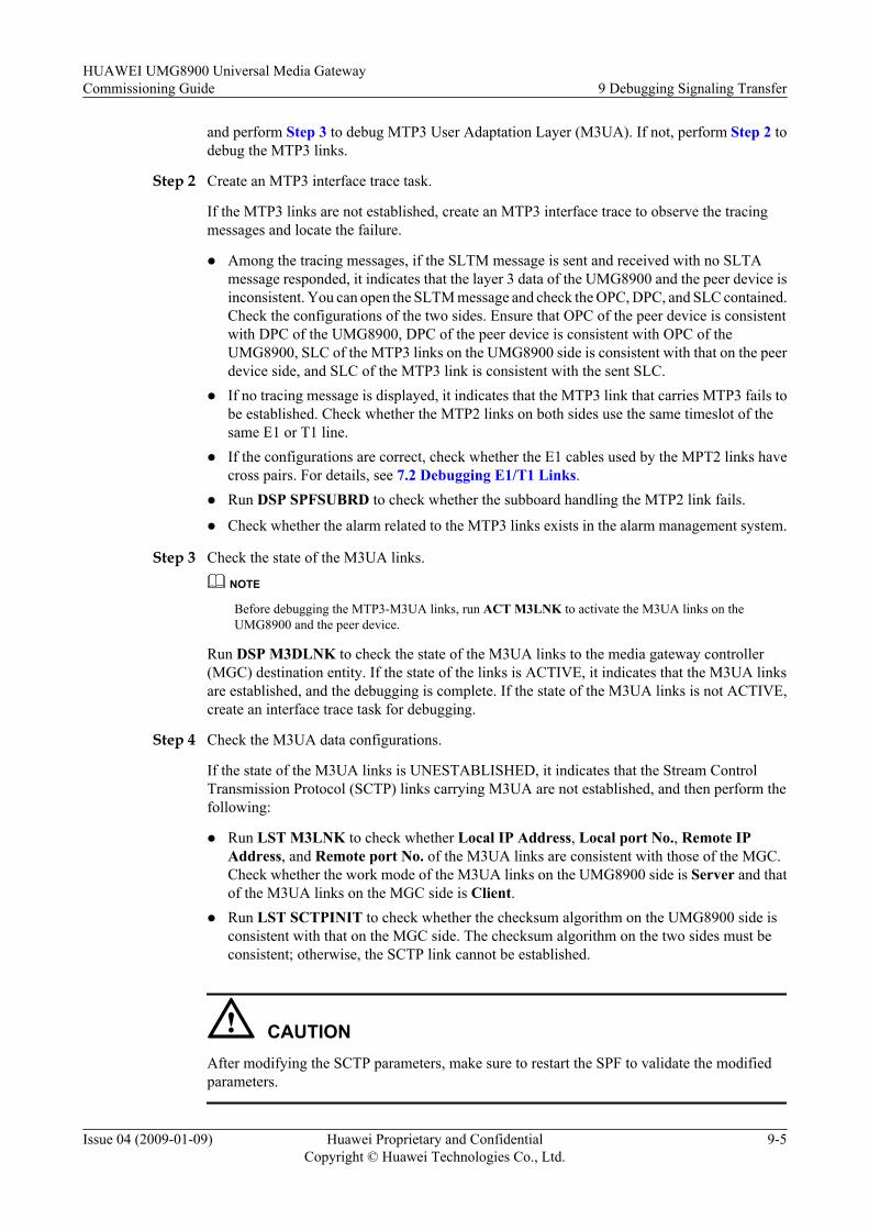
and perform Step 3 to debug MTP3 User Adaptation Layer (M3UA). If not, perform Step 2 todebug the MTP3 links.
Step 2 Create an MTP3 interface trace task.
If the MTP3 links are not established, create an MTP3 interface trace to observe the tracingmessages and locate the failure.
l Among the tracing messages, if the SLTM message is sent and received with no SLTAmessage responded, it indicates that the layer 3 data of the UMG8900 and the peer device isinconsistent. You can open the SLTM message and check the OPC, DPC, and SLC contained.Check the configurations of the two sides. Ensure that OPC of the peer device is consistentwith DPC of the UMG8900, DPC of the peer device is consistent with OPC of theUMG8900, SLC of the MTP3 links on the UMG8900 side is consistent with that on the peerdevice side, and SLC of the MTP3 link is consistent with the sent SLC.
l If no tracing message is displayed, it indicates that the MTP3 link that carries MTP3 fails tobe established. Check whether the MTP2 links on both sides use the same timeslot of thesame E1 or T1 line.
l If the configurations are correct, check whether the E1 cables used by the MPT2 links havecross pairs. For details, see 7.2 Debugging E1/T1 Links.
l Run DSP SPFSUBRD to check whether the subboard handling the MTP2 link fails.
l Check whether the alarm related to the MTP3 links exists in the alarm management system.
Step 3 Check the state of the M3UA links.
NOTE
Before debugging the MTP3-M3UA links, run ACT M3LNK to activate the M3UA links on theUMG8900 and the peer device.
Run DSP M3DLNK to check the state of the M3UA links to the media gateway controller(MGC) destination entity. If the state of the links is ACTIVE, it indicates that the M3UA linksare established, and the debugging is complete. If the state of the M3UA links is not ACTIVE,create an interface trace task for debugging.
Step 4 Check the M3UA data configurations.
If the state of the M3UA links is UNESTABLISHED, it indicates that the Stream ControlTransmission Protocol (SCTP) links carrying M3UA are not established, and then perform thefollowing:
l Run LST M3LNK to check whether Local IP Address, Local port No., Remote IPAddress, and Remote port No. of the M3UA links are consistent with those of the MGC.Check whether the work mode of the M3UA links on the UMG8900 side is Server and thatof the M3UA links on the MGC side is Client.
l Run LST SCTPINIT to check whether the checksum algorithm on the UMG8900 side isconsistent with that on the MGC side. The checksum algorithm on the two sides must beconsistent; otherwise, the SCTP link cannot be established.
CAUTIONAfter modifying the SCTP parameters, make sure to restart the SPF to validate the modifiedparameters.
HUAWEI UMG8900 Universal Media GatewayCommissioning Guide 9 Debugging Signaling Transfer
Issue 04 (2009-01-09) Huawei Proprietary and ConfidentialCopyright © Huawei Technologies Co., Ltd.
9-5
Step 5 Create an M3UA interface trace task.
If the state of the M3UA link is INACTIVE, create an M3UA interface trace task, and observethe tracing message to locate the fault.
l Among the tracing messages, if the UMG8900 receives the ASPAC message from the MGCand responses with ERROR indicating Unsupported traffic handling mode, it indicates thatthe traffic mode of the M3UA link sets configured on the UMG8900 and the MGC areinconsistent. Run RMV M3LKS and ADD M3LKS to set the work mode of the M3UAlinks sets of the UMG8900 consistent with that of the MGC, which may be master/slave orload sharing.
l If the UMG8900 receives the ASPAC message from the MGC and returns the ERRORmessage indicating invalid context, it indicates that the route context of the M3UA destinationentity of the UMG8900 is different from that of the M3UA local destination of the MGC. Inthis case, change them to the same value.
----End
9.3 Debugging MTP3B-M3UA Signaling LinksThis describes how to debug the MTP3B-M3UA signaling links.
Context
The embedded signaling gateway (SG) of the UMG8900 uses the MTP3B-M3UA mode to adaptand transfer radio access network application part (RANAP) on the access network (AN) side,as shown in Figure 9-3.
Figure 9-3 Signaling adaptation and transfer in MTP3B-M3UA mode
SEP UMG8900 MGC
RANAP
MTP3B
RANAP
SCCP
SAAL
ATM ATM
MTP3B M3UASCTP
IP
M3UA
SCTPIP
MAC MAC
RANAP IP
M3UA-NIF
ATM IP
SAAL
SCCP
M3UA: MTP3 User AdaptationLayer
MTP: Message Transfer Part RANAP: radio access networkapplication part
SCCP: signaling connectioncontrol part
NIF: node interworking function MGC: media gateway controller
MAC: media access control SCTP: Stream Control TransmissionProtocol
9 Debugging Signaling TransferHUAWEI UMG8900 Universal Media Gateway
Commissioning Guide
9-6 Huawei Proprietary and ConfidentialCopyright © Huawei Technologies Co., Ltd.
Issue 04 (2009-01-09)
The embedded SG of the UMG8900 uses the MTP3B-M3UA mode to adapt the RANAPsignaling on the radio network controller (RNC) side to the IP packets, and then transfers themto the media gateway controller (MGC).
Procedure
Step 1 Run DSP MTP3BDPC to check whether the state of the destination signaling point (DSP) ofthe RNC is available.
l If yes, it indicates that the Message Transfer Part(broadband) (MTP3B) DSP is reachable.Then perform Step 7 to debug the MTP3 User Adaptation Layer (M3UA) link.
l Otherwise, perform Step 2.
Step 2 Check whether the alarm related to the MTP3B exists in the alarm management system.
l If yes, clear the alarm, and then run DSP MTP3BDPC to check whether the state of the DSPof the RNC is available.
– If the state of the DSP of the RNC is available, it indicates that the MTP3B DSP isreachable. Then perform Step 7.
– Otherwise, perform Step 3.
l If no alarm related to MTP3B exists, perform Step 3.
Step 3 Run LST MTP3BLKS and LST MTP3BLNK to check which Signaling ATM AdaptationLayer (SAAL) link the MTP3B link is carried on. Then, run DSP SAALLNK to check whetherthe SAAL link is normal.
NOTE
If the SAAL link is normal, the following information is displayed:
l LinkStatus = Connected
l SSCOPState =Data Transfer Ready
l SSCFState = In Service/Data Transfer Ready
l If the SAAL link is normal, perform Step 6.
l Otherwise, perform Step 4.
Step 4 Run SET PVCOAM to enable the operation, administration, and maintenance (OAM) functionof the permanent virtual channel (PVC) carrying the SAAL link, and run DSP ASUSTS to checkthe cell statistics received by the PVC. If no OAM fault occurs, it indicates that the PVCconnection is normal.
Step 5 If the SAAL link is abnormal, start the SAAL interface trace task, and check whether anymessage is sent and received, and whether the received message is correct.
NOTE
When the link is normal, the maintenance messages are exchanged POLL and STAT. The messageexchange period is short. The message is SD during link establishment and upper-layer data transfer.
Step 6 Start the MTP3B interface trace task. Check whether any message is sent and received, andwhether the received message (especially OPC, DPC, and SLC) is correct. Check whether theconfigurations between the UMG8900 and the RNC are correct based on the tracing message.
Step 7 Start debugging the M3UA link. Run DSP M3LNK to check the state of the M3UA link to theMGC destination entity.
HUAWEI UMG8900 Universal Media GatewayCommissioning Guide 9 Debugging Signaling Transfer
Issue 04 (2009-01-09) Huawei Proprietary and ConfidentialCopyright © Huawei Technologies Co., Ltd.
9-7
l If the link state is ACTIVE, it indicates that the M3UA link is established. The debugging iscompleted.
l If the link state is UNESTABLISHED, perform Step 8.
l If the link state is INACTIVE, perform Step 9.
Step 8 If the state of the M3UA link is UNESTABLISHED, check the following configuration data:
l Run LST M3LNK to check whether Local IP Address, Local port No., Remote IPAddress, and Remote port No. of the M3UA links are consistent with those of the MGC.At the same time, check whether the work mode of the M3UA links of the UMG8900 isServer and that of the MGC is Client.
l Run LST SCTPINIT to display the Stream Control Transmission Protocol (SCTP)parameters of the M3UA link, and especially check whether the UMG8900 and MGC adoptthe same check algorithm (CRC32 or ADLER32). Different check algorithms result inestablishment failure of the SCTP link.
CAUTIONIf the SCTP Checksum algorithm parameters are inconsistent, run SET SCTPINIT to modifythem. Restart the SPF of the UMG8900 to validate the SCTP parameters.
Step 9 If the state of the M3UA links is INACTIVE, create an M3UA interface trace task on theUMG8900 side, and observe the tracing message:
l Among the tracing messages, if the UMG8900 receives the ACTIVE message from the MGCand returns the ERROR message indicating the unsupported traffic handling mode, itindicates that the traffic modes of the M3UA link sets configured on the UMG8900 and theMGC are different. In this case, run RMV M3LKS and ADD M3LKS to set the traffic modeof the M3UA link set to the same as that on the MGC side (Override_Mode orLoadshare_Mode).
l If the UMG8900 receives the ACTIVE message and returns the ERROR message indicatinginvalid context, it indicates that the route context of the M3UA destination entity of theUMG8900 is different from that of the M3UA local destination of the MGC. In this case,run MOD M3DE to modify them to the consistent value.
----End
9.4 Debugging Q.921-IUA Signaling LinksThis describes how to debug the Q.921-IUA signaling links.
Prerequisite
Before debugging Q.921-IUA signaling links, complete the debugging of E1/T1 interfaces andE1/T1 links on the time division multiplexing (TDM) side and the network layer on the InternetProtocol (IP) side. For how to debug interfaces, see 7.1 Making E1/T1 Self-Loopback Tests,7.2 Debugging E1/T1 Links, and 8.1 Debugging IP Interfaces.
9 Debugging Signaling TransferHUAWEI UMG8900 Universal Media Gateway
Commissioning Guide
9-8 Huawei Proprietary and ConfidentialCopyright © Huawei Technologies Co., Ltd.
Issue 04 (2009-01-09)
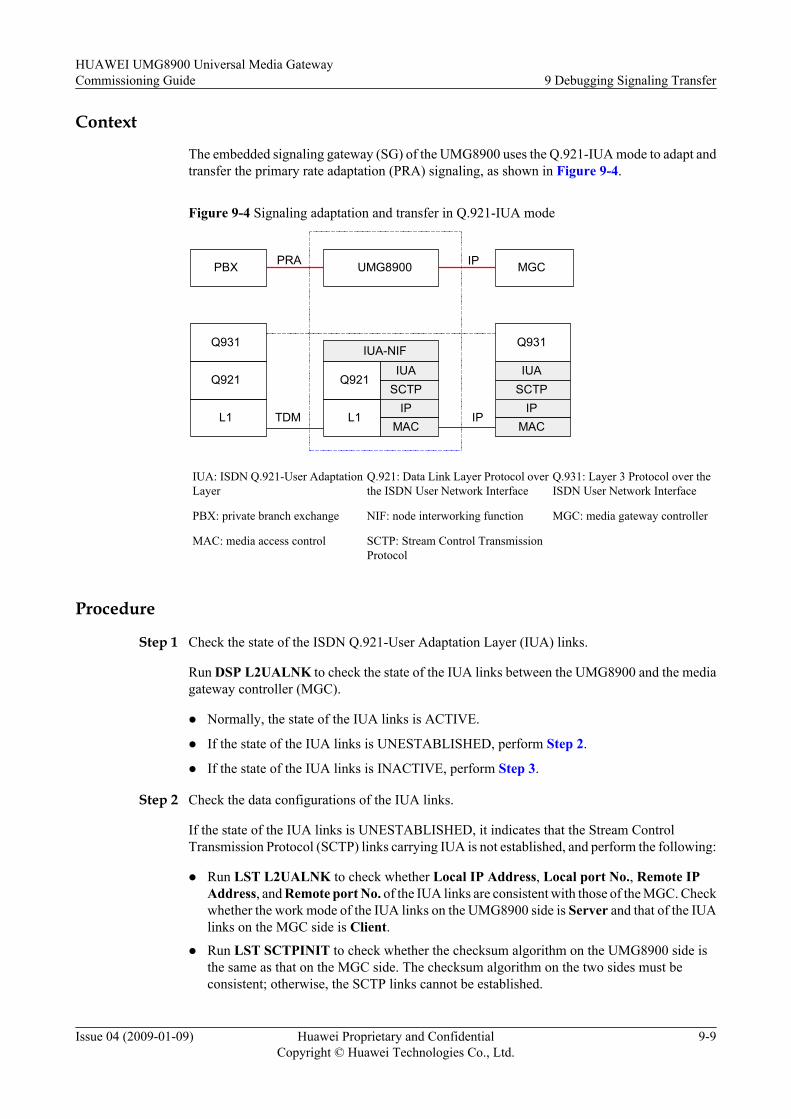
Context
The embedded signaling gateway (SG) of the UMG8900 uses the Q.921-IUA mode to adapt andtransfer the primary rate adaptation (PRA) signaling, as shown in Figure 9-4.
Figure 9-4 Signaling adaptation and transfer in Q.921-IUA mode
PBX UMG8900 MGC
Q931 Q931
Q921
L1 L1
Q921IUA
SCTPIP
IUASCTP
IPMAC MAC
PRA IP
IUA-NIF
TDM IP
IUA: ISDN Q.921-User AdaptationLayer
Q.921: Data Link Layer Protocol overthe ISDN User Network Interface
Q.931: Layer 3 Protocol over theISDN User Network Interface
PBX: private branch exchange NIF: node interworking function MGC: media gateway controller
MAC: media access control SCTP: Stream Control TransmissionProtocol
Procedure
Step 1 Check the state of the ISDN Q.921-User Adaptation Layer (IUA) links.
Run DSP L2UALNK to check the state of the IUA links between the UMG8900 and the mediagateway controller (MGC).
l Normally, the state of the IUA links is ACTIVE.
l If the state of the IUA links is UNESTABLISHED, perform Step 2.
l If the state of the IUA links is INACTIVE, perform Step 3.
Step 2 Check the data configurations of the IUA links.
If the state of the IUA links is UNESTABLISHED, it indicates that the Stream ControlTransmission Protocol (SCTP) links carrying IUA is not established, and perform the following:
l Run LST L2UALNK to check whether Local IP Address, Local port No., Remote IPAddress, and Remote port No. of the IUA links are consistent with those of the MGC. Checkwhether the work mode of the IUA links on the UMG8900 side is Server and that of the IUAlinks on the MGC side is Client.
l Run LST SCTPINIT to check whether the checksum algorithm on the UMG8900 side isthe same as that on the MGC side. The checksum algorithm on the two sides must beconsistent; otherwise, the SCTP links cannot be established.
HUAWEI UMG8900 Universal Media GatewayCommissioning Guide 9 Debugging Signaling Transfer
Issue 04 (2009-01-09) Huawei Proprietary and ConfidentialCopyright © Huawei Technologies Co., Ltd.
9-9
CAUTIONAfter modifying the SCTP parameters, make sure to restart the SPF to validate the modifiedparameters.
Step 3 Create an IUA interface trace task.
If the state of the IUA links is INACTIVE, create an IUA interface trace on the UMG8900 tolocate the fault by checking the tracing message.
l Unsupported traffic handling modeAmong the tracing messages, if the UMG8900 receives AspActive messages from the MGCand returns Error messages indicating the unsupported traffic handling mode,it indicates that the traffic handling mode of the IUA link sets of the UMG8900 is inconsistentwith that of the MGC. Run RMV L2UALKS and ADD L2UALNK to set the mode of theUMG8900 consistent with that of the MGC, which may be master/slave or load sharing.
l Invalid interface identifierAmong the tracing messages, if the UMG8900 receives the AspActive message from theMGC and responses with ERROR indicating the wrong interface ID,it indicates that the interface ID of the Q.921 links of the UMG8900 is inconsistent with thatof the PRA links of the MGC. Run RMV Q921LNK and ADD Q921LNK to modify theinterface ID of the Q.921 links of the UMG8900 consistent with that of the MGC.
l Returning ReleaseIndicationAmong the tracing messages, if the UMG8900 receives the EstablishReq message from theMGC and returns the ReleaseIndication message, it indicates that the Q.921 links are notestablished.Run LST Q921LNK to check whether the Q.921 links of the UMG8900 and MGC occupythe same timeslot of an E1 cable.Check whether the settings of Net/User side are correct. Both the Q.921 links on theUMG8900 side and the PRALINK links on the MGC are set to user side or network side atthe same time. In addition, if the links at the peer exchange are set to network side, the linksof the UMG8900/MGC must be set to user side. It is the same way in the reversed condition.Run DSP SPFSUBRD to check whether the SPF subboard processing the Q.921 links isabnormal.
l Receiving no EstablishRequestIf the UMG8900 does not receive any EstablishRequest message from the MGC, check therelated settings and state of the MGC.
l Unidirectional traced messagesIf the UMG8900 only receives messages from or only sends messages to the MGC, checkthe E1 links for cross pairs.
----End
9.5 Debugging R2 Signaling TransferThis describes how to debug the R2 signaling.
9 Debugging Signaling TransferHUAWEI UMG8900 Universal Media Gateway
Commissioning Guide
9-10 Huawei Proprietary and ConfidentialCopyright © Huawei Technologies Co., Ltd.
Issue 04 (2009-01-09)

Context
The UMG8900 is different from the common channel signaling (CCS) adaptation andtransparent transmission and is based on the standard SIGTRAN protocol. Therefore, it processesR2 channel associated signaling (CAS) through exchanging H.248 messages.
The UMG8900 adapts detected CAS to H.248 messages and reports them to the media gatewaycontroller (MGC) and meanwhile converts received H.248 messages into CAS. Thus, theUMG8900 implements the CAS interworking between the MGC and the public switchedtelephone network (PSTN).
To debug R2 signaling transfer, first check the configuration scripts and port status related toR2. If the local configurations are correct, analyze R2 and H.248 tracing messages to decidewhether the interconnection failure results from faults on the UMG8900, the MGC, or theinterconnected PSTN switch.
Procedure
Step 1 Run DSP CFG to check the configuration data of the line signaling and the register signaling.
Check whether ADD LSND, ADD LRPT, ADD REGRPT, and ADD REGSND are consistentwith the R2 configuration scripts released with the currently used software version.
NOTE
If the pulse signals such as the metering pulse and the digit pulse are used in the line signaling, you mustcheck the setting of ADD PULSE and ADD PCMPLS.
Step 2 Check whether Line signaling conversion index, Line command conversion index, Registersignaling conversion index, and Register command conversion index in ADDCASSIGNAL are correctly set.
These four parameters are respectively equal to ID in ADD LSND, ADD LRPT, ADDREGRPT, and ADD REGSND.
Step 3 Check whether CAS name in ADD CASATTR is consistent with CAS name in ADDCASSIGNAL.
Step 4 Run ADD CASATTR to check whether Address send list and Address receive list are set toonly Destination Number, Source Number, and Calling Subscriber Category; otherwise, the linkcannot be established.
Step 5 Run LST TDMIU to check the E1 port occupied by the R2 trunk. Make sure that Relay typeof TDM timeslot is R2, and CASATTR No. is the same as ID in ADD CASATTR.
NOTE
If the pulse is used in the signaling, ensure that Pulse No. is the same as PCM pulse index in ADDPCMPLS.
If no pulse is used in the signaling, do not set the parameter.
Step 6 Run DSP E1PORT to check the state of the E1 port carrying the R2 signaling according to theport. Normally, the state is OK.
If the state of the E1 port is FAULT, ensure that the line impedance matches the trunk line inuse. If the line impedance does not match the trunk line, you can set the impedance throughsetting the DIP switch. For details, see B.2 Board DIP Switches and Jumpers of all SSMFrames.
HUAWEI UMG8900 Universal Media GatewayCommissioning Guide 9 Debugging Signaling Transfer
Issue 04 (2009-01-09) Huawei Proprietary and ConfidentialCopyright © Huawei Technologies Co., Ltd.
9-11
Make sure that Send Line Coding Scheme, Receive Line Coding Scheme, Send Frame Structure,and Receive Frame Structure are the same as those of the interconnected device. If not, run SETE1PORT to modify them.
Step 7 Check whether the alarm related to the E1 port carrying the R2 signaling exists in the alarmmanagement system.
----End
9 Debugging Signaling TransferHUAWEI UMG8900 Universal Media Gateway
Commissioning Guide
9-12 Huawei Proprietary and ConfidentialCopyright © Huawei Technologies Co., Ltd.
Issue 04 (2009-01-09)
10 Debugging Services
About This Chapter
This describes how to debug voice services, supplementary services, MPTY services, and dataservices.
ContextDebugging services is to debug overall service functions. Before debugging services, make surethat the data configurations are correct and the independent function and interface debugging iscomplete.
The required dialing test tasks and operations vary with different networking applications. Inthe actual deployment, make dialing tests according to the dialing test cases and operation guidesin the HUAWEI UMG8900 Universal Media Gateway Acceptance Manual.
The most direct and efficient way for service debugging is to make dialing tests, that is, to usea service terminal or a dialing test device to trigger service running and then check whether thewhole system can work normally. Make corresponding dialing tests based on different targets.
When a call fails during making dialing tests on services, analyze H.248 protocol tracingmessages to locate the fault.
NOTE
The MGC is considered as an example in the dialing tests of services related to the MGC.
10.1 Debugging Voice ServicesThis describes how to debug the voice services of asynchronous transfer mode (ATM) calls.
10.2 Debugging Supplementary ServicesThis describes how to debug supplementary services.
10.3 Debugging MPTY ServicesThis describes how to debug the multiparty service (MPTY) services.
10.4 Debugging Data ServicesThis describes how to debug the data services.
HUAWEI UMG8900 Universal Media GatewayCommissioning Guide 10 Debugging Services
Issue 04 (2009-01-09) Huawei Proprietary and ConfidentialCopyright © Huawei Technologies Co., Ltd.
10-1
10.1 Debugging Voice ServicesThis describes how to debug the voice services of asynchronous transfer mode (ATM) calls.
Procedure
Step 1 Use a user equipment (UE) to make a voice call test, and check the message transfer part(broadband) (MTP3B), Q.AAL2, and UP interfaces.
Normally, the signaling connection control part (SCCP) and Q.AAL2 messages are sent andreceived through the MTP3B interface. The ERQ message is received and the ECF message issent through the Q.AAL2 interface. The INIT message is sent and received through the UPinterface, and the type of the sent INIT messages is ACK.
l If the call is normal, perform Step 3.
l If the Q.AAL2 link setup fails, check the control plane on the transport layer according to6.4 Debugging Q.AAL2 Links.
l If the messages on the UP interface are abnormal, perform Step 2.
Step 2 Analyze the tracing messages on the UP interface.l If the UMG8900 receives the IuUP initialization message and returns the NACK message,
run LST RFCI to check the rate supported by the UMG8900 and whether the RFCIconfigured on the media gateway (MGW) is less than that of the radio network controller(RNC). If yes, run MOD RFCI to modify the settings of the MGW or decrease the ratesupported by the RNC.
l If the UMG8900 sends the IuUP initialization message and then receives the NACK message,it indicates that the RFCI correction request of the called MGW is rejected by the RNC. Inthis case, check the rates of the calling and called RNCs.
l If the UMG8900 fails to receive the IuUP initialization message from the RNC, the bearerpermanent virtual channels (PVCs) corresponding to the AAL2 paths configured on theUMG8900 and the RNC are inconsistent, and thus UP packet loss occurs. Run DSPAAL2PATH to check whether the configurations are incorrect. If yes, run RMVAAL2PATH and ADD AAL2PATH to modify the configurations.
Step 3 Hold several calls, and perform the following steps:l Run DSP VMGWRSC to display the resource occupation state of the VMGW. The number
of ATM resources occupied must be the same as the number of UEs.l Run DSP AAL2USER to display the state of online ATM users. The total user number on
all ASUs of the Iu interface must be the same as the number of UEs.l Run DSP AAL2CH to display the path occupation state. The number of used channels of
all paths must be the same as the number of UEs.
Step 4 In the case of mass calls setup, run DSP ASUSTS to display call and UP statistics. Accordingto the statistics, determine whether call loss or other faults occur. Here, other faults include thevoice quality faults such as one-way audio, no audio, and noise.
Step 5 Locate the voice quality faults by performing the inloop, outloop, and segment-by-segmentloopback on the specified termination.
Step 6 Start the alarm management system, and check whether any alarm related to the ASU occursduring the call.
10 Debugging ServicesHUAWEI UMG8900 Universal Media Gateway
Commissioning Guide
10-2 Huawei Proprietary and ConfidentialCopyright © Huawei Technologies Co., Ltd.
Issue 04 (2009-01-09)

Step 7 Run LST LOG to query the call tracing log, check whether any failure record exists, and thenanalyze the record.
----End
10.2 Debugging Supplementary ServicesThis describes how to debug supplementary services.
Context
Before debugging the supplementary services, make sure to set the right of the supplementaryservices for users on the HLR.
Procedure
Step 1 Debug the call forwarding unconditional (CFU) service. l A mobile user terminal calls a mobile user terminal, and the call is forwarded to a fixed-line
phone unconditionally.l A fixed-line phone calls a mobile user terminal, and the call is forwarded to a local fixed-
line phone unconditionally.l A mobile user terminal calls a mobile user terminal, and the call is forwarded to another
mobile user terminal unconditionally.
Make each dialing test 10 times. All the calls are connected with clear voice and no obviousnoise.
Step 2 Debug the call forwarding on no reply (CFNRy) service. l A mobile user terminal calls a mobile user terminal, and the call is forwarded to a local fixed-
line phone when no replay is made.l A fixed-line phone calls a mobile user terminal, and the call is forwarded to a local fixed-
line phone when no replay is made.l A mobile user terminal calls a mobile user terminal, and the call is forwarded to another
mobile user terminal when no reply is made.
Make each dialing test 10 times. All the calls are connected with clear voice and no obviousnoise.
Step 3 Debug the call forwarding busy (CFB) service. l A mobile user terminal calls a mobile user terminal, and the call is forwarded to a local fixed-
line phone when the callee is busy.l A fixed-line phone calls a mobile user terminal, and the call is forwarded to a local fixed-
line phone when the callee is busy.l A mobile user terminal calls a mobile user terminal, and the call is forwarded to another
mobile user terminal when the callee is busy.
Make each dialing test 10 times. All the calls are connected with clear voice and no obviousnoise.
Step 4 Debug the call waiting (CW) service.
HUAWEI UMG8900 Universal Media GatewayCommissioning Guide 10 Debugging Services
Issue 04 (2009-01-09) Huawei Proprietary and ConfidentialCopyright © Huawei Technologies Co., Ltd.
10-3
l Set the CW service for mobile user terminal A, and mobile user terminal A calls mobile userterminal B.
l When mobile user terminals A and B are on the call, mobile user terminal C calls mobileuser terminal A, and mobile user terminal C is put on hold.
l Mobile user terminal B hangs up, and mobile user terminal A is put through to mobile userterminal C.
Make the dialing test 10 times. All the calls are connected with clear voice and no obvious noise.
Step 5 Debug the call hold (HOLD) service.l Set the HOLD service for mobile user terminal A, and mobile user terminal A calls mobile
user terminal B.l When mobile user terminals A and B are on the call, mobile user terminal C calls mobile
user terminal A, mobile user terminals C and A are on the call, mobile user terminal B is puton hold.
l When mobile user terminal C hangs up, mobile user terminal A resumes the conversion withmobile user terminal B.
Make the dialing test 10 times. All the calls are connected with clear voice and no obvious noise.
----End
10.3 Debugging MPTY ServicesThis describes how to debug the multiparty service (MPTY) services.
Procedure
Make MPTY service tests. The involving parties cover the fixed-line phone and mobile userterminal. Conferences of two parties, five parties, and six parties are tested.
Make the tests 30 times. All the calls are connected with clear voice and no obvious noise, anda new party can join the conversation.
----End
10.4 Debugging Data ServicesThis describes how to debug the data services.
Procedure
Step 1 Make dialing tests.l A mobile user terminal sends fax to a public switched telephone network (PSTN) user.
l A PSTN user sends fax to a mobile user terminal.
Fax a single page and multiple pages of files, for example, fax 20 pages in succession. Fax iscorrectly received and sent.
Step 2 A mobile user terminal starts the video service to a mobile user terminal.
10 Debugging ServicesHUAWEI UMG8900 Universal Media Gateway
Commissioning Guide
10-4 Huawei Proprietary and ConfidentialCopyright © Huawei Technologies Co., Ltd.
Issue 04 (2009-01-09)
The voice is clear, video is uninterrupted, and voice and video keeps synchronous.
----End
HUAWEI UMG8900 Universal Media GatewayCommissioning Guide 10 Debugging Services
Issue 04 (2009-01-09) Huawei Proprietary and ConfidentialCopyright © Huawei Technologies Co., Ltd.
10-5

A System Commissioning Records
This provides the system commissioning record.
A.1 Preparations for System CommissioningThis provides the records of preparations for system commissioning.
A.2 Data ConfigurationThis provides the record of data configurations.
A.3 Debugging of Local Office HardwareThis provides the record of the debugging of the local office hardware.
A.4 Interconnection DebuggingThis provides the records of interconnection debugging.
A.5 Service DebuggingThis provides the record of service debugging.
HUAWEI UMG8900 Universal Media GatewayCommissioning Guide A System Commissioning Records
Issue 04 (2009-01-09) Huawei Proprietary and ConfidentialCopyright © Huawei Technologies Co., Ltd.
A-1
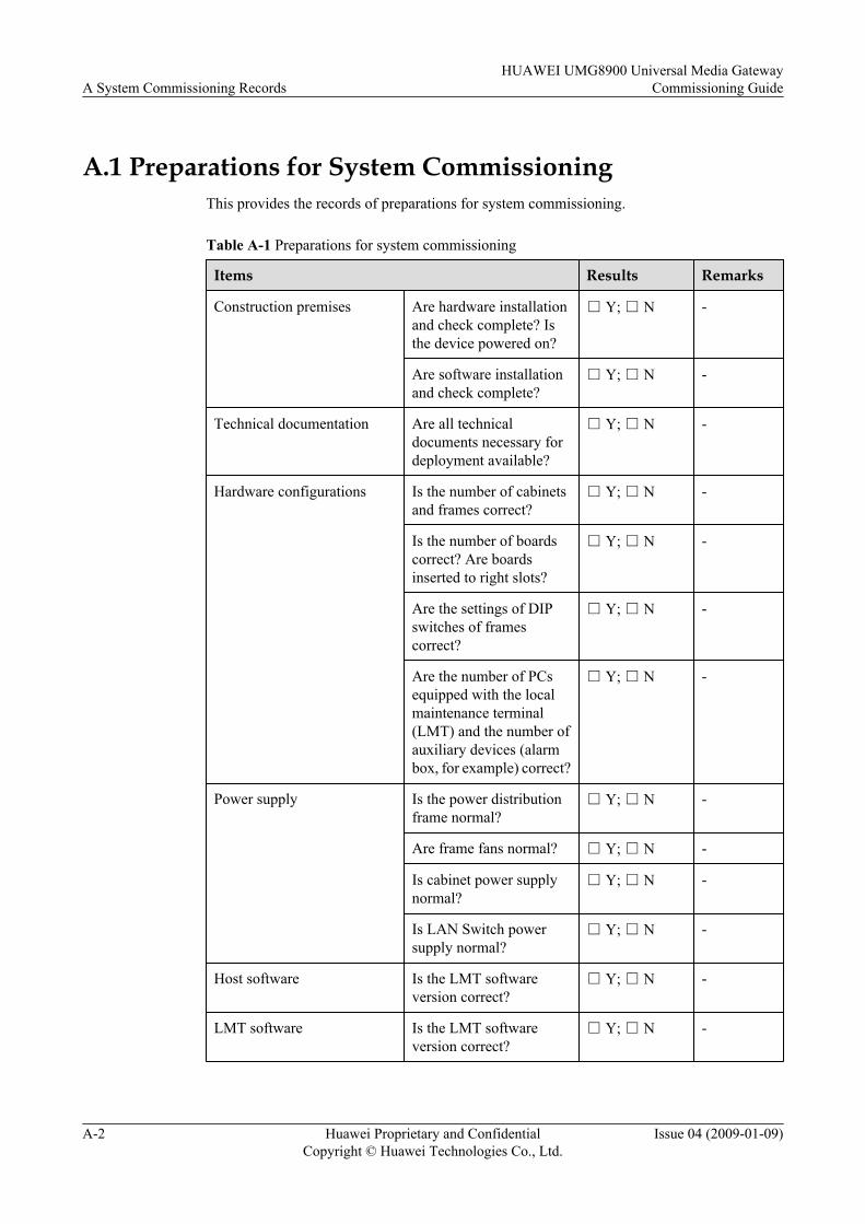
A.1 Preparations for System CommissioningThis provides the records of preparations for system commissioning.
Table A-1 Preparations for system commissioning
Items Results Remarks
Construction premises Are hardware installationand check complete? Isthe device powered on?
□ Y; □ N -
Are software installationand check complete?
□ Y; □ N -
Technical documentation Are all technicaldocuments necessary fordeployment available?
□ Y; □ N -
Hardware configurations Is the number of cabinetsand frames correct?
□ Y; □ N -
Is the number of boardscorrect? Are boardsinserted to right slots?
□ Y; □ N -
Are the settings of DIPswitches of framescorrect?
□ Y; □ N -
Are the number of PCsequipped with the localmaintenance terminal(LMT) and the number ofauxiliary devices (alarmbox, for example) correct?
□ Y; □ N -
Power supply Is the power distributionframe normal?
□ Y; □ N -
Are frame fans normal? □ Y; □ N -
Is cabinet power supplynormal?
□ Y; □ N -
Is LAN Switch powersupply normal?
□ Y; □ N -
Host software Is the LMT softwareversion correct?
□ Y; □ N -
LMT software Is the LMT softwareversion correct?
□ Y; □ N -
A System Commissioning RecordsHUAWEI UMG8900 Universal Media Gateway
Commissioning Guide
A-2 Huawei Proprietary and ConfidentialCopyright © Huawei Technologies Co., Ltd.
Issue 04 (2009-01-09)
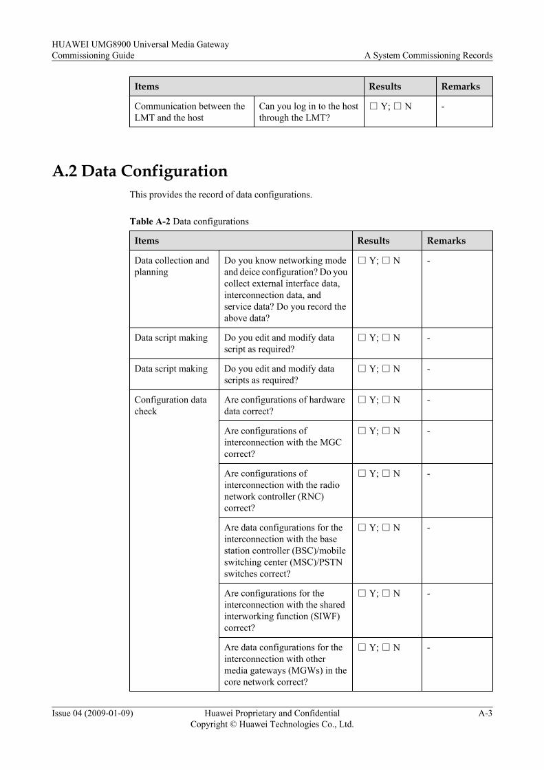
Items Results Remarks
Communication between theLMT and the host
Can you log in to the hostthrough the LMT?
□ Y; □ N -
A.2 Data ConfigurationThis provides the record of data configurations.
Table A-2 Data configurations
Items Results Remarks
Data collection andplanning
Do you know networking modeand deice configuration? Do youcollect external interface data,interconnection data, andservice data? Do you record theabove data?
□ Y; □ N -
Data script making Do you edit and modify datascript as required?
□ Y; □ N -
Data script making Do you edit and modify datascripts as required?
□ Y; □ N -
Configuration datacheck
Are configurations of hardwaredata correct?
□ Y; □ N -
Are configurations ofinterconnection with the MGCcorrect?
□ Y; □ N -
Are configurations ofinterconnection with the radionetwork controller (RNC)correct?
□ Y; □ N -
Are data configurations for theinterconnection with the basestation controller (BSC)/mobileswitching center (MSC)/PSTNswitches correct?
□ Y; □ N -
Are configurations for theinterconnection with the sharedinterworking function (SIWF)correct?
□ Y; □ N -
Are data configurations for theinterconnection with othermedia gateways (MGWs) in thecore network correct?
□ Y; □ N -
HUAWEI UMG8900 Universal Media GatewayCommissioning Guide A System Commissioning Records
Issue 04 (2009-01-09) Huawei Proprietary and ConfidentialCopyright © Huawei Technologies Co., Ltd.
A-3

Items Results Remarks
Are data configurations ofsignaling transfer correct?
□ Y; □ N -
Are configurations of serviceresource parameters correct?
□ Y; □ N -
A.3 Debugging of Local Office HardwareThis provides the record of the debugging of the local office hardware.
Table A-3 Debugging of local office hardware
Items Results Remarks
Switch time Is the switch time accurate with anerror less than ± 30 seconds comparedwith the local standard time?
□ Y; □ N -
Clock Are clock cables correctly connected? □ Y; □ N -
Is the CLK in the main control framein the locked state?
□ Y; □ N -
Are the NETs in all frames in thelocked state?
□ Y; □ N -
Is the number of the slips of the E1port used for extracting clock signals0?
□ Y; □ N -
Debuggingcascading
Are cascading cables correctlyconnected?
□ Y; □ N -
Are indicators of all cascadinginterfaces (FE/GE/TDM) in normalstate?
□ Y; □ N -
Is the cascading board (BLU/FLU)working normally?
□ Y; □ N -
Does an alarm related to cascadingchannels exist in the alarmmanagement system?
□ Y; □ N -
Indicator state Is the LAN Switch indicator innormal state?
□ Y; □ N -
Is the power distribution frameindicator in normal state?
□ Y; □ N -
A System Commissioning RecordsHUAWEI UMG8900 Universal Media Gateway
Commissioning Guide
A-4 Huawei Proprietary and ConfidentialCopyright © Huawei Technologies Co., Ltd.
Issue 04 (2009-01-09)
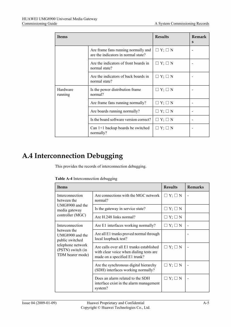
Items Results Remarks
Are frame fans running normally andare the indicators in normal state?
□ Y; □ N -
Are the indicators of front boards innormal state?
□ Y; □ N -
Are the indicators of back boards innormal state?
□ Y; □ N -
Hardwarerunning
Is the power distribution framenormal?
□ Y; □ N -
Are frame fans running normally? □ Y; □ N -
Are boards running normally? □ Y; □ N -
Is the board software version correct? □ Y; □ N -
Can 1+1 backup boards be switchednormally?
□ Y; □ N -
A.4 Interconnection DebuggingThis provides the records of interconnection debugging.
Table A-4 Interconnection debugging
Items Results Remarks
Interconnectionbetween theUMG8900 and themedia gatewaycontroller (MGC)
Are connections with the MGC networknormal?
□ Y; □ N -
Is the gateway in service state? □ Y; □ N
Are H.248 links normal? □ Y; □ N
Interconnectionbetween theUMG8900 and thepublic switchedtelephone network(PSTN) switch (inTDM bearer mode)
Are E1 interfaces working normally? □ Y; □ N -
Are all E1 trunks proved normal throughlocal loopback test?
-
Are calls over all E1 trunks establishedwith clear voice when dialing tests aremade on a specified E1 trunk?
□ Y; □ N -
Are the synchronous digital hierarchy(SDH) interfaces working normally?
□ Y; □ N -
Does an alarm related to the SDHinterface exist in the alarm managementsystem?
□ Y; □ N -
HUAWEI UMG8900 Universal Media GatewayCommissioning Guide A System Commissioning Records
Issue 04 (2009-01-09) Huawei Proprietary and ConfidentialCopyright © Huawei Technologies Co., Ltd.
A-5
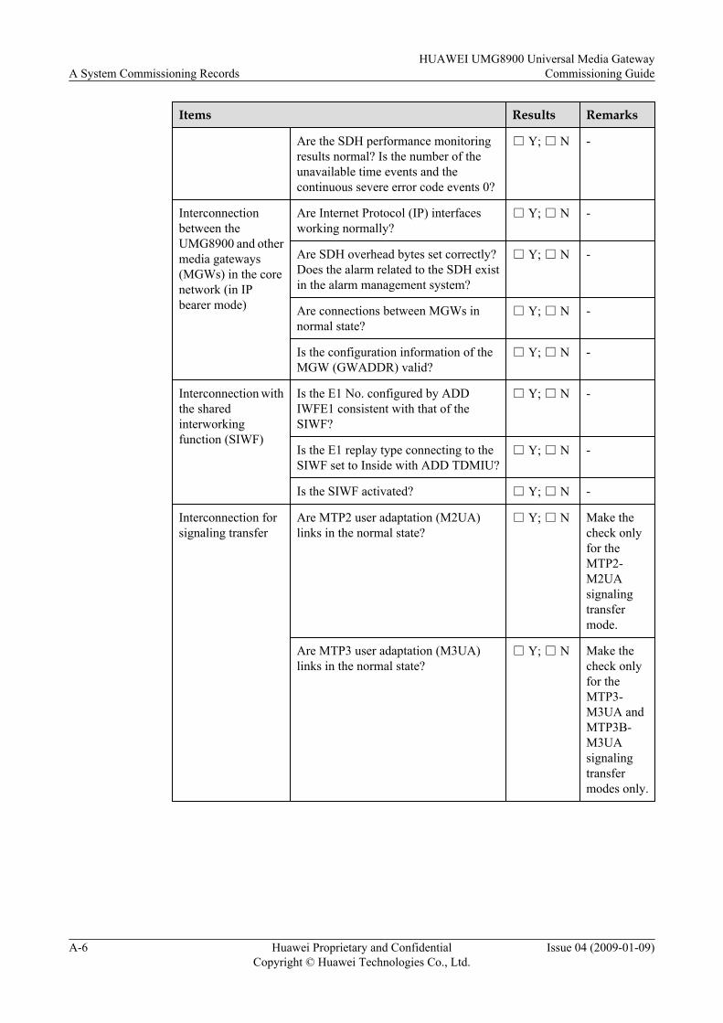
Items Results Remarks
Are the SDH performance monitoringresults normal? Is the number of theunavailable time events and thecontinuous severe error code events 0?
□ Y; □ N -
Interconnectionbetween theUMG8900 and othermedia gateways(MGWs) in the corenetwork (in IPbearer mode)
Are Internet Protocol (IP) interfacesworking normally?
□ Y; □ N -
Are SDH overhead bytes set correctly?Does the alarm related to the SDH existin the alarm management system?
□ Y; □ N -
Are connections between MGWs innormal state?
□ Y; □ N -
Is the configuration information of theMGW (GWADDR) valid?
□ Y; □ N -
Interconnection withthe sharedinterworkingfunction (SIWF)
Is the E1 No. configured by ADDIWFE1 consistent with that of theSIWF?
□ Y; □ N -
Is the E1 replay type connecting to theSIWF set to Inside with ADD TDMIU?
□ Y; □ N -
Is the SIWF activated? □ Y; □ N -
Interconnection forsignaling transfer
Are MTP2 user adaptation (M2UA)links in the normal state?
□ Y; □ N Make thecheck onlyfor theMTP2-M2UAsignalingtransfermode.
Are MTP3 user adaptation (M3UA)links in the normal state?
□ Y; □ N Make thecheck onlyfor theMTP3-M3UA andMTP3B-M3UAsignalingtransfermodes only.
A System Commissioning RecordsHUAWEI UMG8900 Universal Media Gateway
Commissioning Guide
A-6 Huawei Proprietary and ConfidentialCopyright © Huawei Technologies Co., Ltd.
Issue 04 (2009-01-09)

Items Results Remarks
Are MTP3 links in the normal state? □ Y; □ N Make thecheck onlyfor theMTP3-M3UAsignalingtransfermode.
Are MTP3B links in the normal state? □ Y; □ N Make thecheck onlyfor theMTP3B-M3UAsignalingtransfermode.
Is the version of the R2 signalingadaptation scripts consistent with theversion of the deployment software?
□ Y; □ N Use theconfiguration scripts ofthedeploymentsoftware.
Is the configuration data of the R2signaling transfer correct?
□ Y; □ N -
A.5 Service DebuggingThis provides the record of service debugging.
Table A-5 Service debugging
Item Results Remarks
Voice servicedebugging
Is the call between a UE and afixed-line phone connected withclear voice?
□ Y; □ N -
Is the call between userequipments (UEs) connectedwith clear voice?
□ Y; □ N -
Supplementaryservicedebugging
Is the call forwardingunconditional (CFU) servicenormal and with clear voice?
□ Y; □ N -
HUAWEI UMG8900 Universal Media GatewayCommissioning Guide A System Commissioning Records
Issue 04 (2009-01-09) Huawei Proprietary and ConfidentialCopyright © Huawei Technologies Co., Ltd.
A-7
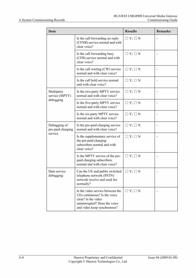
Item Results Remarks
Is the call forwarding no reply(CFNR) service normal and withclear voice?
□ Y; □ N -
Is the call forwarding busy(CFB) service normal and withclear voice?
□ Y; □ N -
Is the call waiting (CW) servicenormal and with clear voice?
□ Y; □ N -
Is the call hold service normaland with clear voice?
□ Y; □ N -
Multipartyservice (MPTY)debugging
Is the two-party MPTY servicenormal and with clear voice?
□ Y; □ N -
Is the five-party MPTY servicenormal and with clear voice?
□ Y; □ N -
Is the six-party MPTY servicenormal and with clear voice?
□ Y; □ N -
Debugging ofpre-paid chargingservice
Is the pre-paid charging servicenormal and with clear voice?
□ Y; □ N -
Is the supplementary service ofthe pre-paid chargingsubscribers normal and withclear voice?
□ Y; □ N -
Is the MPTY service of the pre-paid charging subscribersnormal and with clear voice?
□ Y; □ N -
Data servicedebugging
Can the UE and public switchedtelephone network (PSTN)network receive and send faxnormally?
□ Y; □ N -
Is the video service between theUEs continuous? Is the voiceclear? Is the videouninterrupted? Does the voiceand video keep synchronous?
□ Y; □ N -
A System Commissioning RecordsHUAWEI UMG8900 Universal Media Gateway
Commissioning Guide
A-8 Huawei Proprietary and ConfidentialCopyright © Huawei Technologies Co., Ltd.
Issue 04 (2009-01-09)
B Settings of DIP Switches of Frames andBoards
This describes how to set the dial in-line package (DIP) switches of frames and boards.
B.1 Settings of DIP Switches of FramesThis describes the settings of the dial in-line package (DIP) switches of frames.
B.2 Board DIP Switches and Jumpers of all SSM Frames
HUAWEI UMG8900 Universal Media GatewayCommissioning Guide B Settings of DIP Switches of Frames and Boards
Issue 04 (2009-01-09) Huawei Proprietary and ConfidentialCopyright © Huawei Technologies Co., Ltd.
B-1
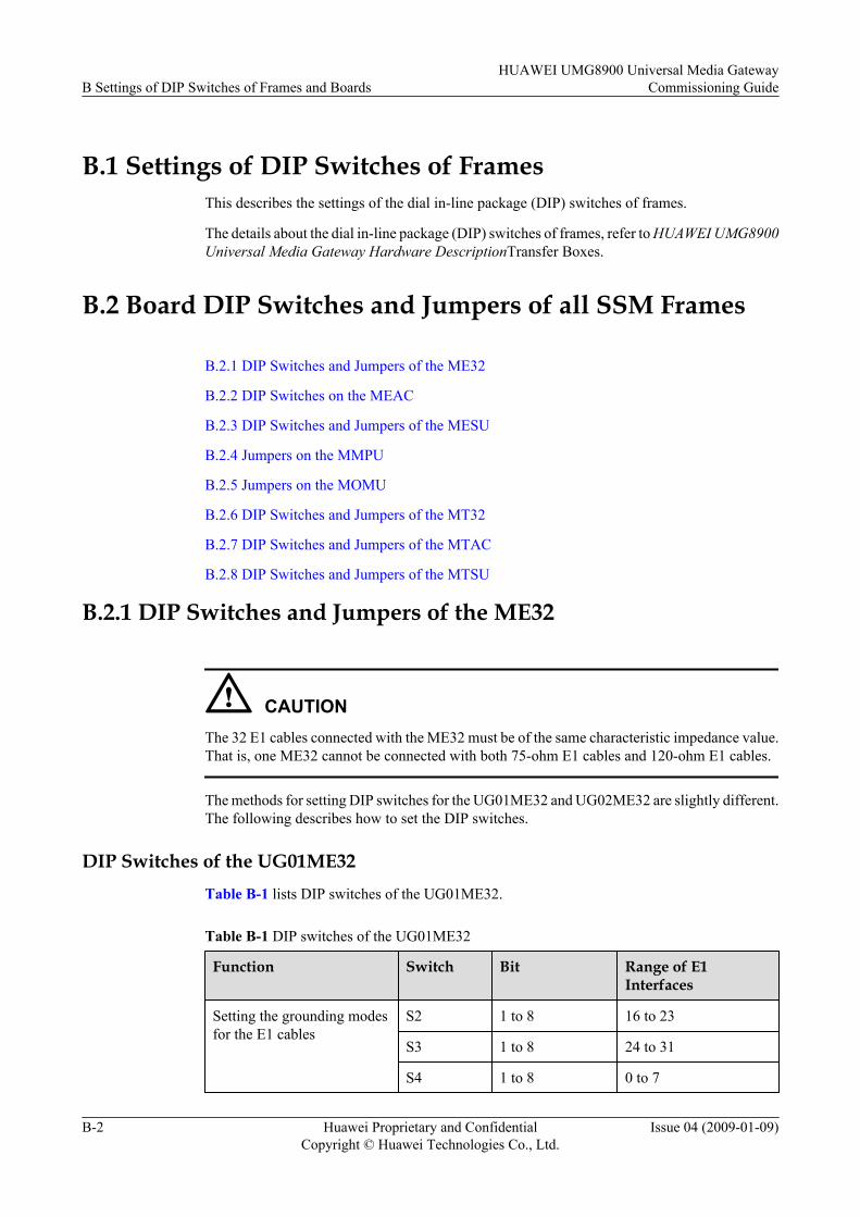
B.1 Settings of DIP Switches of FramesThis describes the settings of the dial in-line package (DIP) switches of frames.
The details about the dial in-line package (DIP) switches of frames, refer to HUAWEI UMG8900Universal Media Gateway Hardware DescriptionTransfer Boxes.
B.2 Board DIP Switches and Jumpers of all SSM Frames
B.2.1 DIP Switches and Jumpers of the ME32
B.2.2 DIP Switches on the MEAC
B.2.3 DIP Switches and Jumpers of the MESU
B.2.4 Jumpers on the MMPU
B.2.5 Jumpers on the MOMU
B.2.6 DIP Switches and Jumpers of the MT32
B.2.7 DIP Switches and Jumpers of the MTAC
B.2.8 DIP Switches and Jumpers of the MTSU
B.2.1 DIP Switches and Jumpers of the ME32
CAUTIONThe 32 E1 cables connected with the ME32 must be of the same characteristic impedance value.That is, one ME32 cannot be connected with both 75-ohm E1 cables and 120-ohm E1 cables.
The methods for setting DIP switches for the UG01ME32 and UG02ME32 are slightly different.The following describes how to set the DIP switches.
DIP Switches of the UG01ME32Table B-1 lists DIP switches of the UG01ME32.
Table B-1 DIP switches of the UG01ME32
Function Switch Bit Range of E1Interfaces
Setting the grounding modesfor the E1 cables
S2 1 to 8 16 to 23
S3 1 to 8 24 to 31
S4 1 to 8 0 to 7
B Settings of DIP Switches of Frames and BoardsHUAWEI UMG8900 Universal Media Gateway
Commissioning Guide
B-2 Huawei Proprietary and ConfidentialCopyright © Huawei Technologies Co., Ltd.
Issue 04 (2009-01-09)
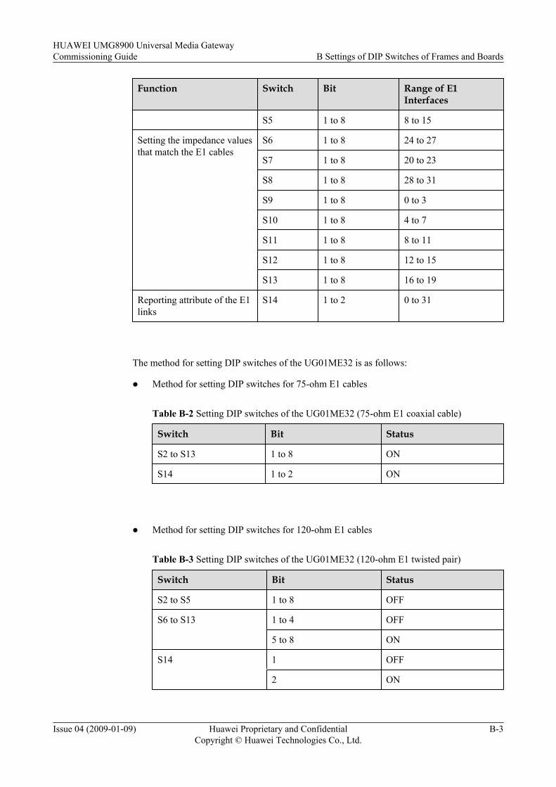
Function Switch Bit Range of E1Interfaces
S5 1 to 8 8 to 15
Setting the impedance valuesthat match the E1 cables
S6 1 to 8 24 to 27
S7 1 to 8 20 to 23
S8 1 to 8 28 to 31
S9 1 to 8 0 to 3
S10 1 to 8 4 to 7
S11 1 to 8 8 to 11
S12 1 to 8 12 to 15
S13 1 to 8 16 to 19
Reporting attribute of the E1links
S14 1 to 2 0 to 31
The method for setting DIP switches of the UG01ME32 is as follows:
l Method for setting DIP switches for 75-ohm E1 cables
Table B-2 Setting DIP switches of the UG01ME32 (75-ohm E1 coaxial cable)
Switch Bit Status
S2 to S13 1 to 8 ON
S14 1 to 2 ON
l Method for setting DIP switches for 120-ohm E1 cables
Table B-3 Setting DIP switches of the UG01ME32 (120-ohm E1 twisted pair)
Switch Bit Status
S2 to S5 1 to 8 OFF
S6 to S13 1 to 4 OFF
5 to 8 ON
S14 1 OFF
2 ON
HUAWEI UMG8900 Universal Media GatewayCommissioning Guide B Settings of DIP Switches of Frames and Boards
Issue 04 (2009-01-09) Huawei Proprietary and ConfidentialCopyright © Huawei Technologies Co., Ltd.
B-3
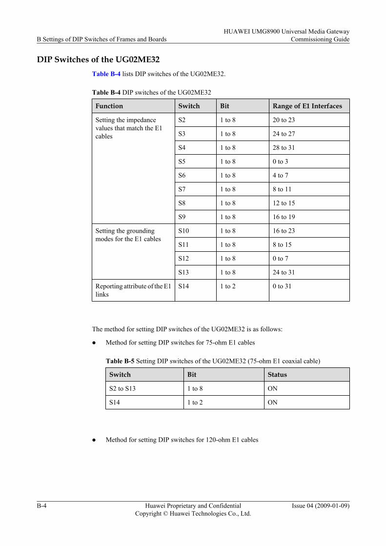
DIP Switches of the UG02ME32Table B-4 lists DIP switches of the UG02ME32.
Table B-4 DIP switches of the UG02ME32
Function Switch Bit Range of E1 Interfaces
Setting the impedancevalues that match the E1cables
S2 1 to 8 20 to 23
S3 1 to 8 24 to 27
S4 1 to 8 28 to 31
S5 1 to 8 0 to 3
S6 1 to 8 4 to 7
S7 1 to 8 8 to 11
S8 1 to 8 12 to 15
S9 1 to 8 16 to 19
Setting the groundingmodes for the E1 cables
S10 1 to 8 16 to 23
S11 1 to 8 8 to 15
S12 1 to 8 0 to 7
S13 1 to 8 24 to 31
Reporting attribute of the E1links
S14 1 to 2 0 to 31
The method for setting DIP switches of the UG02ME32 is as follows:
l Method for setting DIP switches for 75-ohm E1 cables
Table B-5 Setting DIP switches of the UG02ME32 (75-ohm E1 coaxial cable)
Switch Bit Status
S2 to S13 1 to 8 ON
S14 1 to 2 ON
l Method for setting DIP switches for 120-ohm E1 cables
B Settings of DIP Switches of Frames and BoardsHUAWEI UMG8900 Universal Media Gateway
Commissioning Guide
B-4 Huawei Proprietary and ConfidentialCopyright © Huawei Technologies Co., Ltd.
Issue 04 (2009-01-09)
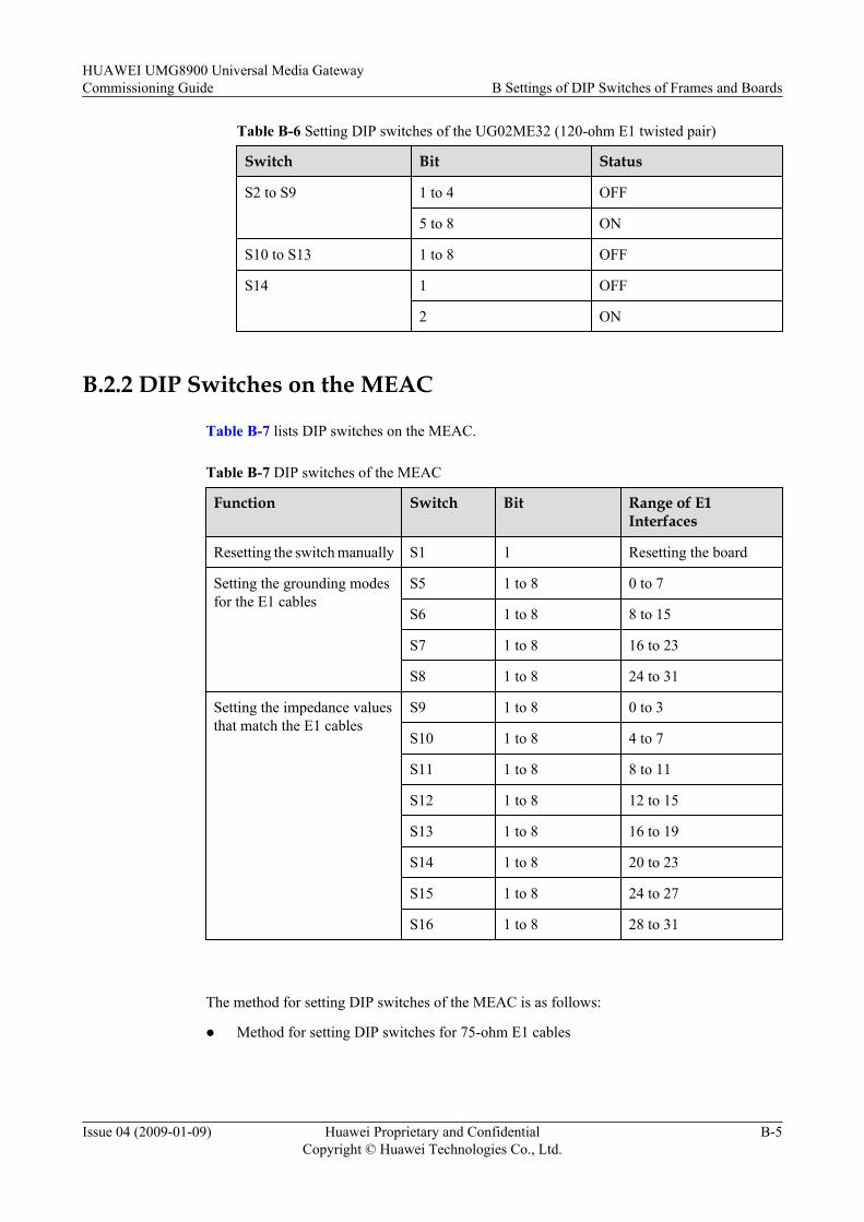
Table B-6 Setting DIP switches of the UG02ME32 (120-ohm E1 twisted pair)
Switch Bit Status
S2 to S9 1 to 4 OFF
5 to 8 ON
S10 to S13 1 to 8 OFF
S14 1 OFF
2 ON
B.2.2 DIP Switches on the MEAC
Table B-7 lists DIP switches on the MEAC.
Table B-7 DIP switches of the MEAC
Function Switch Bit Range of E1Interfaces
Resetting the switch manually S1 1 Resetting the board
Setting the grounding modesfor the E1 cables
S5 1 to 8 0 to 7
S6 1 to 8 8 to 15
S7 1 to 8 16 to 23
S8 1 to 8 24 to 31
Setting the impedance valuesthat match the E1 cables
S9 1 to 8 0 to 3
S10 1 to 8 4 to 7
S11 1 to 8 8 to 11
S12 1 to 8 12 to 15
S13 1 to 8 16 to 19
S14 1 to 8 20 to 23
S15 1 to 8 24 to 27
S16 1 to 8 28 to 31
The method for setting DIP switches of the MEAC is as follows:
l Method for setting DIP switches for 75-ohm E1 cables
HUAWEI UMG8900 Universal Media GatewayCommissioning Guide B Settings of DIP Switches of Frames and Boards
Issue 04 (2009-01-09) Huawei Proprietary and ConfidentialCopyright © Huawei Technologies Co., Ltd.
B-5
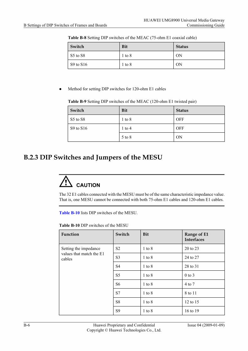
Table B-8 Setting DIP switches of the MEAC (75-ohm E1 coaxial cable)
Switch Bit Status
S5 to S8 1 to 8 ON
S9 to S16 1 to 8 ON
l Method for setting DIP switches for 120-ohm E1 cables
Table B-9 Setting DIP switches of the MEAC (120-ohm E1 twisted pair)
Switch Bit Status
S5 to S8 1 to 8 OFF
S9 to S16 1 to 4 OFF
5 to 8 ON
B.2.3 DIP Switches and Jumpers of the MESU
CAUTIONThe 32 E1 cables connected with the MESU must be of the same characteristic impedance value.That is, one MESU cannot be connected with both 75-ohm E1 cables and 120-ohm E1 cables.
Table B-10 lists DIP switches of the MESU.
Table B-10 DIP switches of the MESU
Function Switch Bit Range of E1Interfaces
Setting the impedancevalues that match the E1cables
S2 1 to 8 20 to 23
S3 1 to 8 24 to 27
S4 1 to 8 28 to 31
S5 1 to 8 0 to 3
S6 1 to 8 4 to 7
S7 1 to 8 8 to 11
S8 1 to 8 12 to 15
S9 1 to 8 16 to 19
B Settings of DIP Switches of Frames and BoardsHUAWEI UMG8900 Universal Media Gateway
Commissioning Guide
B-6 Huawei Proprietary and ConfidentialCopyright © Huawei Technologies Co., Ltd.
Issue 04 (2009-01-09)

Function Switch Bit Range of E1Interfaces
Setting the grounding modesfor the E1 cables
S10 1 to 8 16 to 23
S11 1 to 8 8 to 15
S12 1 to 8 0 to 7
S13 1 to 8 24 to 31
Reporting attribute of the E1links
S14 1 to 2 0 to 31
The method for setting DIP switches of the MESU is as follows:
l Method for setting DIP switches for 75-ohm E1 cables
Table B-11 Setting DIP switches of the MESU (75-ohm E1 coaxial cable)
Switch Bit Status
S2 to S13 1 to 8 ON
S14 1 to 2 ON
l Method for setting DIP switches for 120-ohm E1 cables
Table B-12 Setting DIP switches of the MESU (120-ohm E1 twisted pair)
Switch Bit Status
S2 to S9 1 to 4 OFF
5 to 8 ON
S10 to S13 1 to 8 OFF
S14 1 OFF
2 ON
B.2.4 Jumpers on the MMPU
The jumper JP13 is available on the MMPU to choose packet switching modules to load. TableB-13 lists the setting.
HUAWEI UMG8900 Universal Media GatewayCommissioning Guide B Settings of DIP Switches of Frames and Boards
Issue 04 (2009-01-09) Huawei Proprietary and ConfidentialCopyright © Huawei Technologies Co., Ltd.
B-7
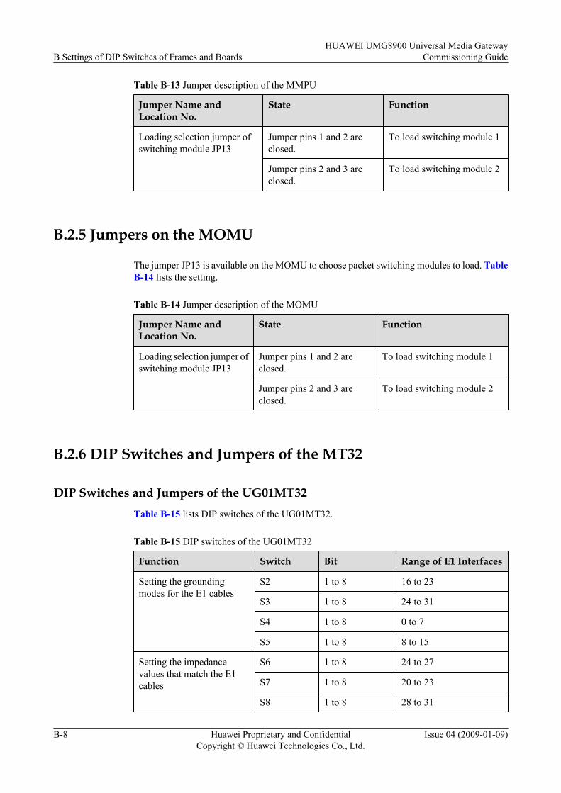
Table B-13 Jumper description of the MMPU
Jumper Name andLocation No.
State Function
Loading selection jumper ofswitching module JP13
Jumper pins 1 and 2 areclosed.
To load switching module 1
Jumper pins 2 and 3 areclosed.
To load switching module 2
B.2.5 Jumpers on the MOMU
The jumper JP13 is available on the MOMU to choose packet switching modules to load. TableB-14 lists the setting.
Table B-14 Jumper description of the MOMU
Jumper Name andLocation No.
State Function
Loading selection jumper ofswitching module JP13
Jumper pins 1 and 2 areclosed.
To load switching module 1
Jumper pins 2 and 3 areclosed.
To load switching module 2
B.2.6 DIP Switches and Jumpers of the MT32
DIP Switches and Jumpers of the UG01MT32Table B-15 lists DIP switches of the UG01MT32.
Table B-15 DIP switches of the UG01MT32
Function Switch Bit Range of E1 Interfaces
Setting the groundingmodes for the E1 cables
S2 1 to 8 16 to 23
S3 1 to 8 24 to 31
S4 1 to 8 0 to 7
S5 1 to 8 8 to 15
Setting the impedancevalues that match the E1cables
S6 1 to 8 24 to 27
S7 1 to 8 20 to 23
S8 1 to 8 28 to 31
B Settings of DIP Switches of Frames and BoardsHUAWEI UMG8900 Universal Media Gateway
Commissioning Guide
B-8 Huawei Proprietary and ConfidentialCopyright © Huawei Technologies Co., Ltd.
Issue 04 (2009-01-09)
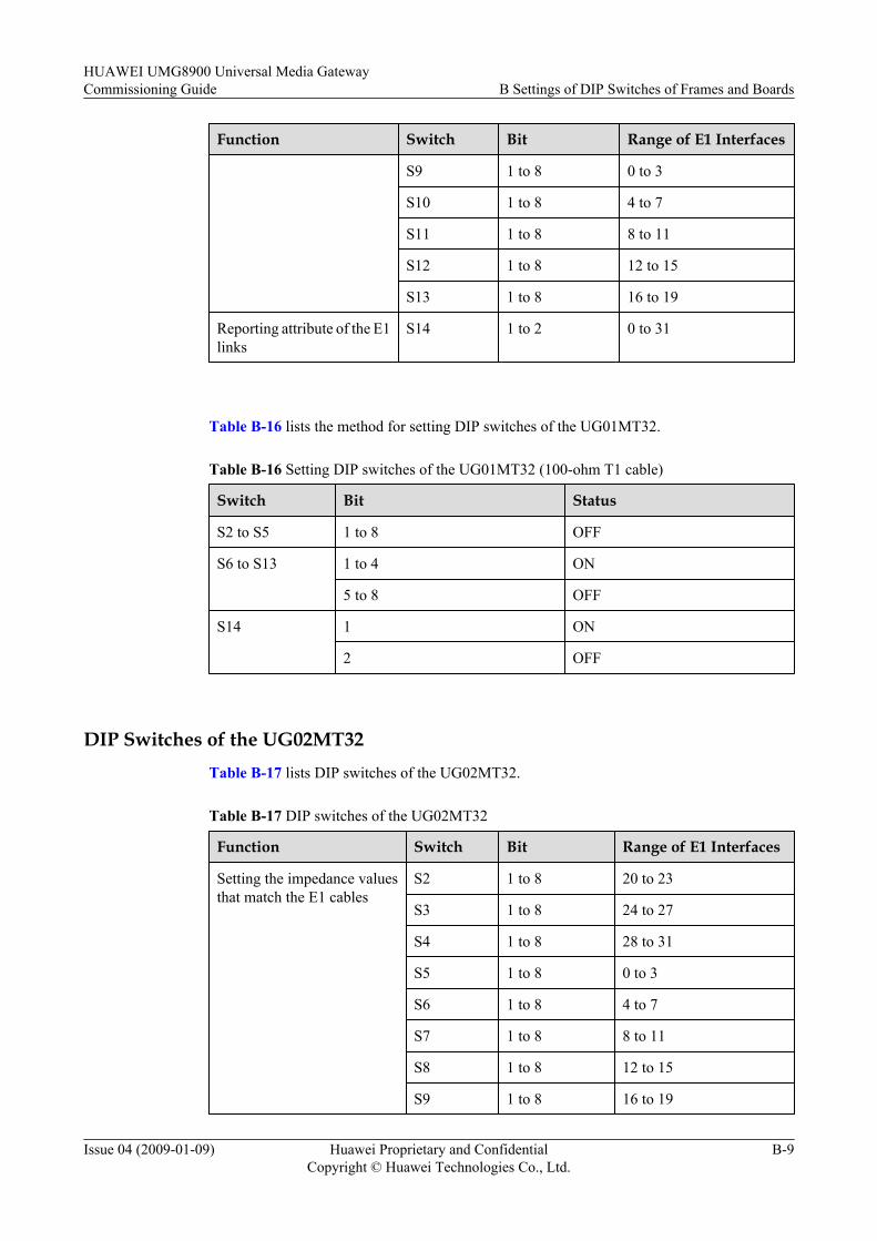
Function Switch Bit Range of E1 Interfaces
S9 1 to 8 0 to 3
S10 1 to 8 4 to 7
S11 1 to 8 8 to 11
S12 1 to 8 12 to 15
S13 1 to 8 16 to 19
Reporting attribute of the E1links
S14 1 to 2 0 to 31
Table B-16 lists the method for setting DIP switches of the UG01MT32.
Table B-16 Setting DIP switches of the UG01MT32 (100-ohm T1 cable)
Switch Bit Status
S2 to S5 1 to 8 OFF
S6 to S13 1 to 4 ON
5 to 8 OFF
S14 1 ON
2 OFF
DIP Switches of the UG02MT32Table B-17 lists DIP switches of the UG02MT32.
Table B-17 DIP switches of the UG02MT32
Function Switch Bit Range of E1 Interfaces
Setting the impedance valuesthat match the E1 cables
S2 1 to 8 20 to 23
S3 1 to 8 24 to 27
S4 1 to 8 28 to 31
S5 1 to 8 0 to 3
S6 1 to 8 4 to 7
S7 1 to 8 8 to 11
S8 1 to 8 12 to 15
S9 1 to 8 16 to 19
HUAWEI UMG8900 Universal Media GatewayCommissioning Guide B Settings of DIP Switches of Frames and Boards
Issue 04 (2009-01-09) Huawei Proprietary and ConfidentialCopyright © Huawei Technologies Co., Ltd.
B-9
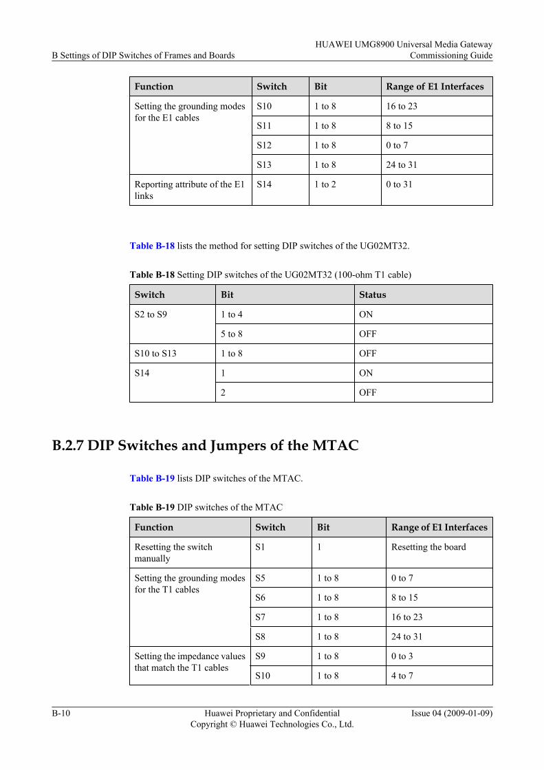
Function Switch Bit Range of E1 Interfaces
Setting the grounding modesfor the E1 cables
S10 1 to 8 16 to 23
S11 1 to 8 8 to 15
S12 1 to 8 0 to 7
S13 1 to 8 24 to 31
Reporting attribute of the E1links
S14 1 to 2 0 to 31
Table B-18 lists the method for setting DIP switches of the UG02MT32.
Table B-18 Setting DIP switches of the UG02MT32 (100-ohm T1 cable)
Switch Bit Status
S2 to S9 1 to 4 ON
5 to 8 OFF
S10 to S13 1 to 8 OFF
S14 1 ON
2 OFF
B.2.7 DIP Switches and Jumpers of the MTAC
Table B-19 lists DIP switches of the MTAC.
Table B-19 DIP switches of the MTAC
Function Switch Bit Range of E1 Interfaces
Resetting the switchmanually
S1 1 Resetting the board
Setting the grounding modesfor the T1 cables
S5 1 to 8 0 to 7
S6 1 to 8 8 to 15
S7 1 to 8 16 to 23
S8 1 to 8 24 to 31
Setting the impedance valuesthat match the T1 cables
S9 1 to 8 0 to 3
S10 1 to 8 4 to 7
B Settings of DIP Switches of Frames and BoardsHUAWEI UMG8900 Universal Media Gateway
Commissioning Guide
B-10 Huawei Proprietary and ConfidentialCopyright © Huawei Technologies Co., Ltd.
Issue 04 (2009-01-09)
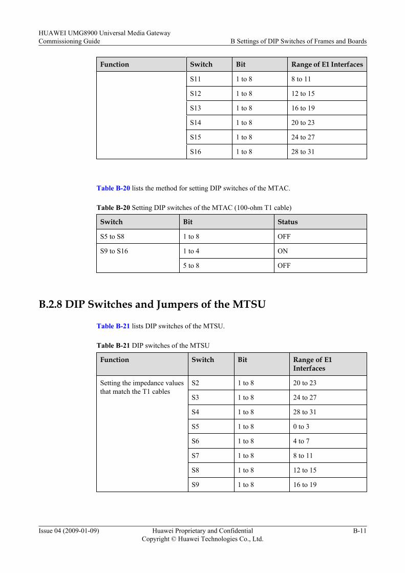
Function Switch Bit Range of E1 Interfaces
S11 1 to 8 8 to 11
S12 1 to 8 12 to 15
S13 1 to 8 16 to 19
S14 1 to 8 20 to 23
S15 1 to 8 24 to 27
S16 1 to 8 28 to 31
Table B-20 lists the method for setting DIP switches of the MTAC.
Table B-20 Setting DIP switches of the MTAC (100-ohm T1 cable)
Switch Bit Status
S5 to S8 1 to 8 OFF
S9 to S16 1 to 4 ON
5 to 8 OFF
B.2.8 DIP Switches and Jumpers of the MTSU
Table B-21 lists DIP switches of the MTSU.
Table B-21 DIP switches of the MTSU
Function Switch Bit Range of E1Interfaces
Setting the impedance valuesthat match the T1 cables
S2 1 to 8 20 to 23
S3 1 to 8 24 to 27
S4 1 to 8 28 to 31
S5 1 to 8 0 to 3
S6 1 to 8 4 to 7
S7 1 to 8 8 to 11
S8 1 to 8 12 to 15
S9 1 to 8 16 to 19
HUAWEI UMG8900 Universal Media GatewayCommissioning Guide B Settings of DIP Switches of Frames and Boards
Issue 04 (2009-01-09) Huawei Proprietary and ConfidentialCopyright © Huawei Technologies Co., Ltd.
B-11
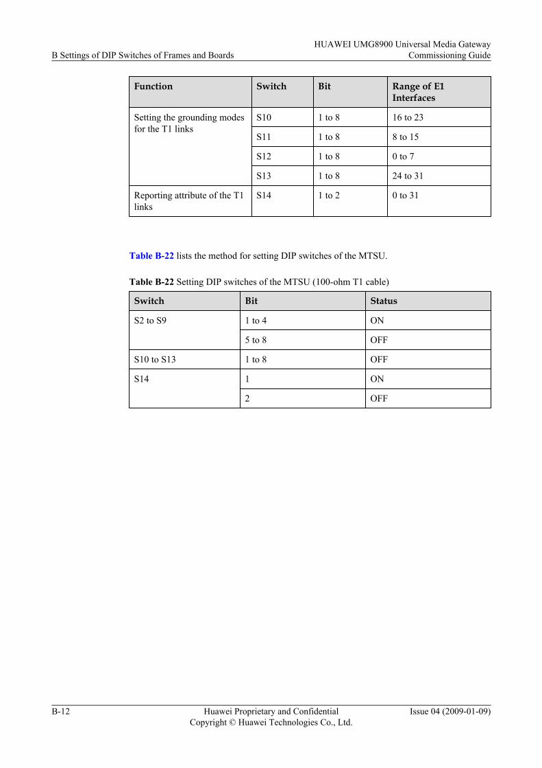
Function Switch Bit Range of E1Interfaces
Setting the grounding modesfor the T1 links
S10 1 to 8 16 to 23
S11 1 to 8 8 to 15
S12 1 to 8 0 to 7
S13 1 to 8 24 to 31
Reporting attribute of the T1links
S14 1 to 2 0 to 31
Table B-22 lists the method for setting DIP switches of the MTSU.
Table B-22 Setting DIP switches of the MTSU (100-ohm T1 cable)
Switch Bit Status
S2 to S9 1 to 4 ON
5 to 8 OFF
S10 to S13 1 to 8 OFF
S14 1 ON
2 OFF
B Settings of DIP Switches of Frames and BoardsHUAWEI UMG8900 Universal Media Gateway
Commissioning Guide
B-12 Huawei Proprietary and ConfidentialCopyright © Huawei Technologies Co., Ltd.
Issue 04 (2009-01-09)
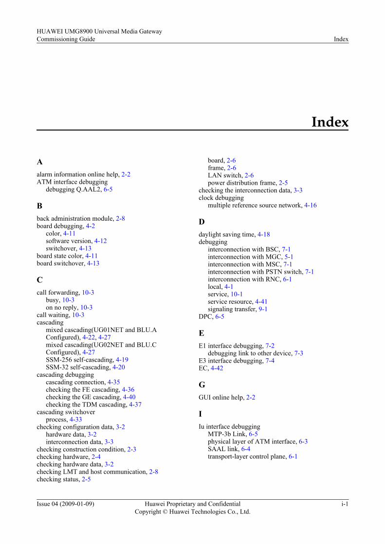
Index
Aalarm information online help, 2-2ATM interface debugging
debugging Q.AAL2, 6-5
Bback administration module, 2-8board debugging, 4-2
color, 4-11software version, 4-12switchover, 4-13
board state color, 4-11board switchover, 4-13
Ccall forwarding, 10-3
busy, 10-3on no reply, 10-3
call waiting, 10-3cascading
mixed cascading(UG01NET and BLU.AConfigured), 4-22, 4-27mixed cascading(UG02NET and BLU.CConfigured), 4-27SSM-256 self-cascading, 4-19SSM-32 self-cascading, 4-20
cascading debuggingcascading connection, 4-35checking the FE cascading, 4-36checking the GE cascading, 4-40checking the TDM cascading, 4-37
cascading switchoverprocess, 4-33
checking configuration data, 3-2hardware data, 3-2interconnection data, 3-3
checking construction condition, 2-3checking hardware, 2-4checking hardware data, 3-2checking LMT and host communication, 2-8checking status, 2-5
board, 2-6frame, 2-6LAN switch, 2-6power distribution frame, 2-5
checking the interconnection data, 3-3clock debugging
multiple reference source network, 4-16
Ddaylight saving time, 4-18debugging
interconnection with BSC, 7-1interconnection with MGC, 5-1interconnection with MSC, 7-1interconnection with PSTN switch, 7-1interconnection with RNC, 6-1local, 4-1service, 10-1service resource, 4-41signaling transfer, 9-1
DPC, 6-5
EE1 interface debugging, 7-2
debugging link to other device, 7-3E3 interface debugging, 7-4EC, 4-42
GGUI online help, 2-2
IIu interface debugging
MTP-3b Link, 6-5physical layer of ATM interface, 6-3SAAL link, 6-4transport-layer control plane, 6-1
HUAWEI UMG8900 Universal Media GatewayCommissioning Guide Index
Issue 04 (2009-01-09) Huawei Proprietary and ConfidentialCopyright © Huawei Technologies Co., Ltd.
i-1

Llocal debugging, 4-1
board, 4-11clock, 4-14system time, 4-17
MMc interface debugging
gateway registration function, 5-4MML command online help, 2-2MTP-3b link debugging
checking configuration, 6-5MTP-3b-M3UA signaling transfer, 9-1MTP2-M2UA signaling link debugging, 9-2
checking M2UA link configuration, 9-2creating M2UA interface tracing task, 9-3
MTP2-M2UA signaling transfer, 9-1MTP3-M3UA signaling link debugging
checking MTP3 link status, 9-5creating MTP3 interface tracing task, 9-5
MTP3-M3UA signaling transfer, 9-1
Oonline help, 2-2OPC, 6-5
Ppackage of document, 2-2preparation
checking construction condition, 2-3checking hardware, 2-4checking software version, 2-7checking status, 2-5checking technical document, 2-2
preparations, 2-1
QQ.AAL2 debugging
testing call, 6-5
RRANAP, 9-6reference document, 2-2
SSDH flag, 7-5SDH interface protection debugging, 7-6service debugging
debugging data service, 10-4debugging MPTY service, 10-4
debugging supplementary service, 10-3service resource debugging, 4-42
debugging IWF resource, 4-44debugging MPTY resource, 4-43
signaling transfer debuggingMTP-3b-M3UA signaling link, 9-6MTP3-M3UA signaling link, 9-4
SLC, 6-5system commissioning, 1-2, 1-3system commissioning process, 1-2system time debugging
checking NTP Server, 4-18checking time zone, 4-17
Ttechnical document, 2-2
IndexHUAWEI UMG8900 Universal Media Gateway
Commissioning Guide
i-2 Huawei Proprietary and ConfidentialCopyright © Huawei Technologies Co., Ltd.
Issue 04 (2009-01-09)