commissioning and early experiments of the phelix facility
TRANSCRIPT

Appl Phys B (2010) 100: 137–150DOI 10.1007/s00340-009-3855-7
Commissioning and early experiments of the PHELIX facility
V. Bagnoud · B. Aurand · A. Blazevic · S. Borneis · C. Bruske · B. Ecker ·U. Eisenbarth · J. Fils · A. Frank · E. Gaul · S. Goette · C. Haefner · T. Hahn ·K. Harres · H.-M. Heuck · D. Hochhaus · D.H.H. Hoffmann · D. Javorková ·H.-J. Kluge · T. Kuehl · S. Kunzer · M. Kreutz · T. Merz-Mantwill · P. Neumayer ·E. Onkels · D. Reemts · O. Rosmej · M. Roth · T. Stoehlker · A. Tauschwitz ·B. Zielbauer · D. Zimmer · K. Witte
Received: 12 October 2009 / Published online: 17 December 2009© The Author(s) 2009. This article is published with open access at Springerlink.com
Abstract At the Helmholtz center GSI, PHELIX (PetawattHigh Energy Laser for heavy Ion eXperiments) has beencommissioned for operation in stand-alone mode and, incombination with ions accelerated up to an energy of13 MeV/u by the heavy ion accelerator UNILAC. The com-bination of PHELIX with the heavy-ion beams available atGSI enables a large variety of unique experiments. Novelresearch opportunities are spanning from the study of ion–matter interaction, through challenging new experiments in
V. Bagnoud (�) · A. Blazevic · S. Borneis · C. Bruske ·B. Ecker · U. Eisenbarth · J. Fils · S. Goette · T. Hahn ·H.-J. Kluge · T. Kuehl · S. Kunzer · M. Kreutz ·T. Merz-Mantwill · E. Onkels · D. Reemts · O. Rosmej ·T. Stoehlker · A. Tauschwitz · B. Zielbauer · D. Zimmer · K. WitteGSI Helmholtzzentrum für Schwerionenforschung GmbH,Planckstr. 1, 64291 Darmstadt, Germanye-mail: [email protected]
V. Bagnoud · A. Blazevic · B. Ecker · J. Fils · T. Stoehlker ·B. ZielbauerHelmholtz Institut Jena, Max Wien Platz 1, 07745 Jena, Germany
B. Aurand · D. Hochhaus · P. NeumayerExtreMe Matter Institute EMMI, GSI Helmholtzzentrum fürSchwerionenforschung GmbH, Planckstr. 1, 64291 Darmstadt,Germany
B. Aurand · B. Ecker · T. Kuehl · D. ZimmerInstitut für Physik, Johannes Gutenberg-Universität Mainz,Staudingerweg 7, 55128 Mainz, Germany
A. Frank · K. Harres · D.H.H. Hoffmann · M. RothInstitut für Kernphysik, Technische Universität Darmstadt,64289 Darmstadt, Germany
E. GaulUniversity of Texas at Austin, Austin, TX 78712, USA
atomic physics, nuclear physics, and astrophysics, into thefield of relativistic plasma physics.
1 Introduction
In the recent years, the commissioning and operation ofhigh-energy petawatt lasers’ (HEPW) facilities [1–3] aroundthe world has enabled tremendous developments in the fieldof high-energy-density physics (HEDP) [4]. Motivated pri-marily by the needs for high-brilliance X-ray sources used in
C. HaefnerLawrence Livermore National Laboratory, Livermore, CA 94550,USA
H.-M. HeuckLeica Microsystems CMS GmbH, Ernst-Leitz-Str. 17-37,35578 Wetzlar, Germany
D. Hochhaus · P. NeumayerGoethe-Universität Frankfurt am Main, Senckenberganlage 31,60325 Frankfurt am Main, Germany
D. JavorkováPhysikalisches Institut, Westfälische Wilhelms-Universität,Wilhelm-Klemm-Str. 10, 48149 Münster, Germany
H.-J. Kluge · T. StoehlkerPhysikalisches Institut, Ruprecht-Karls-Universität Heidelberg,69120 Heidelberg, Germany
D. ZimmerLASERIX-CLUPS, LIXAM UMR 8624, Université Paris-Sud 11,Bât. 350, 91405 Orsay Cedex, France
Present address:K. WitteCentre for Advanced Laser Applications, LMU Munich,Am Coulombwall 1, 85748 Garching, Germany

138 V. Bagnoud et al.
radiographic and spectral diagnostic setups, developmentsin the field of HEPW also show possible applications toemerging new fields like proton radiography, for instance. Inthese cases, the laser is used as a diagnostic tool that probesa sample prepared in a state relevant to HEDP or warm densematter (WDM) studies. These states of matter are relevant toastrophysics as they represent conditions prevalent duringsupernovae explosion, in astrophysical jets or giant planetinteriors.
At the Helmholtz-center GSI, heavy-ion beams are ex-ploited to reach homogeneous WDM conditions for targetof substantial sizes or as a probe to answer still-outstandingquestions about energy loss of ions in plasma targets.These capabilities will be further enhanced when the newFAIR accelerator facility for antiproton research [5] willbe commissioned. The interest in this field is in particu-lar reflected in the large number of countries participat-ing in the HEDgeHOB [6] and WDM [7] collaborationsin charge of developing these experiments. A HEPW laseradds an essential diagnostic capability to the setups envi-sioned and justified the development of a Petawatt HighEnergy Laser for Heavy Ion Experiments (PHELIX) [8]in close proximity with the activities of GSI in the realmof plasma physics [9] and atomic physics [10]. In addi-tion, recent developments in laser-generated particle ac-celeration open a new field of investigation at the inter-face between plasma physics and traditional acceleratorphysics.
In this paper, we report on the commissioning of thePHELIX facility and also on the first experimental resultsobtained at the facility. PHELIX is a hybrid Ti:sapphire/Nd:glass laser system using large aperture amplifiers fromthe former Nova and Phebus laser systems at the LawrenceLivermore National Laboratory in the USA and the CEALimeil-Valenton center in France, respectively. The laserserves three experimental areas that exploit the various ca-pabilities of the machine. The facility is meant to be a user-oriented facility where beam-time is granted based on therecommendation of an international advisory committee thatmeets and inspects experiment proposals on a regular ba-sis. Additionally, PHELIX is a member of the integratedinitiative of European laser research infrastructures, Laser-lab [11], and offers beam-time as such to the scientist ofEuropean laboratories.
After a short overview of the laser architecture, the pa-per focuses on technological aspects that are unique tothe PHELIX facility. Then, in the second part, a reviewof the first experimental results involving PHELIX is pre-sented. This includes results obtained in combined laser andion beam experiments on the ion stopping power of laser-generated plasma, laser-generated coherent and incoherentX-ray sources, and particle acceleration.
2 Overview of the PHELIX facility
The overview of PHELIX presented in Fig. 1 shows theschematic arrangement of the laser building and its neigh-boring experimental area (Z6) in the UNIversal Linear Ac-celerator (UNILAC) hall of GSI. The femtosecond front-endis used to generate the short sub-picosecond pulses. It con-sists of a commercial femtosecond laser oscillator (CoherentMira) delivering pulses with a duration of 100 fs and ener-gies around 4 nJ at a repetition rate of 76 MHz. The oscilla-tor is synchronized to an external clock using the low-jitterSynchrolockTM option from the same vendor. This external76 MHz RF oscillator is also used to generate the timing sig-nals of the facility, while a signal synthesizer is foreseen forfuture use with the GSI 108 MHz reference clock. The pulseis temporally stretched to 2.3 ns full-width half maximum(FWHM) in a pulse stretcher whose architecture is a mod-ified version of the stretcher architecture found in [1]. Thepulse stretcher clips the spectrum at 12 nm because of thefinite size of the optical grating used in its setup. The pulsesare then amplified by two titanium-doped sapphire regener-ative amplifiers with a repetition rate of 10 Hz. The first oneis set up in a linear configuration while the second one is aring amplifier. The typical output energy after the ring re-generative amplifier is 30 mJ. Using ultra fast Pockels cellsthe achievable intensity contrast ratio is better than 60 dB.
For experiments requiring pulses in the nanosecondregime, a nanosecond front-end allows generating laserpulses with durations between 700 ps and 20 ns withprogrammable pulse shapes. The major part of the sys-tem is fiber-based, employing a commercial continuous-wave (CW) single-mode laser source (Koheras Basik), anacousto-optical modulator generating pulse slices of 100 ns,a double-pass fiber amplifier and an intensity modulatorwhich is driven by a programmable waveform genera-tor (Tektronix AWG510). The fiber system delivers pulseenergies up to 10 nJ. A flash-lamp-pumped regenerativeNd:glass ring amplifier amplifies the pulses to energies up to20 mJ with a repetition rate of 0.5 Hz. The timings signalsfor the nanosecond front-end are generated locally at PHE-LIX during maintenance and alignment, but for experimentsit is derived from the linear accelerator of GSI, leading to asynchronization of the ion and laser pulses typically betterthan 1 nanosecond.
Depending on the application the pulses generated byfemtosecond front-end or the nanosecond front-end are thenfurther amplified in the pre-amplifier. The pre-amplifier em-ploys three flash-lamp-pumped Nd:glass amplifiers (2 ×19 mm diameter, and 1 × 45 mm). The input beam deliv-ered by the front-end is stepwise magnified by Keppler tele-scopes up to a maximum exit beam diameter of 70 mm inorder to keep the fluence within safe limits, below the dam-age threshold. Furthermore, a deformable mirror (Night N

Commissioning and early experiments of the PHELIX facility 139
Fig. 1 Schematics of the PHELIX laser system. The beam is presently used at three different target stations: 1. X-ray lab; 2. Target chamber afterpassing the compressor; 3. Target station “Z-6” at the heavy-ion accelerator beam-line in the UNILAC hall
Ltd.), located at the end of the amplifier, can correct wave-front aberrations. This mirror is actively driven in a closed-loop system, which utilizes a Shack–Hartmann sensor as awavefront measurement device. Using this scheme, we suc-cessfully demonstrated correction of the on-shot aberrationsof PHELIX, up to the end of the main amplifier, such that thespot profile available during alignment of the system corre-sponds accurately to the spot shape during the shots. Afterthe pre-amplifier, the laser pulses of up to 10 J can be senteither to the X-ray lab, or to the main amplifier.
The main amplifier is set up in a double-pass configu-ration using five flash-lamp-pumped Nd:glass NOVA andPHEBUS amplifiers. The amplifier hardware was refur-bished to make it compatible with the use in a CPA system.In particular, the Nd:glass slabs were re-polished to λ/10transmitted wavefront quality. The whole amplifier sectionwas folded in order to fit within the building footprint. Thedouble pass architecture is using geometrical separation ofthe incoming and outgoing pulses in the spatial filter. Withamplifier modules having an individual clear aperture of31.5 cm, 28-cm-diameter beams are successfully amplifiedand transported throughout the system; and the correspond-ing output energy available for the experiments exceeds 1 kJ
for 10 ns pulses. This energy is only limited by the laserdamage threshold of the Faraday isolator protecting the laseragainst possible back reflections.
At this point, the beam enters a switch yard where it cantravel through a periscope and a telescope over 70 meters itto the UNILAC hall where combined laser and ion experi-ments can be done. Special care has been taken in design-ing the periscope mirror holders such as to avoid sagging,a source of astigmatism, and vibration, a source of point-ing errors. At the Z6 target chamber, impact of the beamtransport on the beam quality is minimal, while the point-ing stability is about 10 µrad, peak-to-valley. The beam isfocused into the target chamber using lens with a 4-m longfocal length and a phase plate. In this way, a uniform inten-sity distribution is created over a 1-mm large area, at a lo-cation where the ion beam has a 0.5-mm diameter. The ionpulse and the laser meet with a jitter of 1 ns, peak-to-valley.In addition, a second nanosecond laser beam generated bythe nhelix laser [12] is available at this location, either asa three-color probe or a second heating source up to 100 J.All three beams can be synchronized on the target with a jit-ter of 1 ns using the UNILAC 108 MHz clock as a timingreference.

140 V. Bagnoud et al.
Table 1 Present operational parameters of the PHELIX laser system.The temporal intensity contrast is given at 1 ns and 40 ps before themain pulse reaches its maximum for the long pulse and short pulse,respectively
Long pulse Short pulse
Pulse duration 0.7–20 ns 0.4–20 ps
Energy 0.3–1 kJ 120 J
Max intensity 1016 W/cm2 1020 W/cm2
Repetition rate at 1 shot every 90 min 1 shot every 90 min
maximum power
Intensity contrast 50 dB 60 dB
As an alternative to the use in nanosecond regime at Z6,the short pulse capability of PHELIX can be exploited in thelaser bay after the pulses are compressed. The pulse com-pressor uses multi-layer dielectric (MLD) gratings (HoribaJobin-Yvon, France) which span 47 cm in the horizontal di-rection (dispersion) and 33 cm in the vertical direction. Anincidence angle at the gratings of 72° results in lower align-ment and pointing sensitivity at the expense of a largely in-creased size of the compressor tank. In this geometry, theincident beam profile is horizontally limited to 12 cm due tothe size of the gratings. In the vertical direction, the currentlyused beam extension is 24 cm so that the beam is elliptical.In order to achieve an optimal use of this area, the beamis shaped using lithographically produced serrated aperturescombined with spatial filtering. This serrated aperture is lo-cated between the front-end and the pre-amplifier. The max-imum output energy after the pulse compressor is limited bythe damage threshold of the final grating. For 10- to 50-ps-long pulses, the maximal throughput energy is 200 J. For theshortest pulses, below 1 ps duration, it is reduced to 120 J.This corresponds to a nominal peak power of 300 TW for400 fs pulses. An overview of the laser parameters can befound in Table 1 that summarizes the laser output character-istics as a function of the type of operation (long or shortpulse).
The operation of the whole laser facility, which consistsin the routine alignment checks and the control of the shotsequence from the control room, is centralized by the PHE-LIX control system (PCS). The PCS is based on an in-house-developed control system framework also in use inother places [13], and it uses an object-oriented approachimplemented with the LabVIEW programming language.Currently running distributed on 20 computers, this event-driven software architecture is, in addition, readily scalable.About 10,000 process variables are handled to guarantee thesafe operation of the laser. Practically, this corresponds tothe remote operation of more than 50 actuators and 25 cam-eras for the alignment of the laser beam, loading and firingthe capacitor banks of the pre-amplifier and main-amplifierflash-lamps, the collection of the laser parameters during the
shot (e.g., pulse energy, pulse profile, spatial energy densitydistribution in the near and far fields), and the automatic han-dling of interlocks and timing signals relevant to a machine-safe operation of the facility.
3 Commissioning of the main amplifier section
The main amplifier section of the laser is based on flash-lamp-pumped Nd:glass amplifier modules. These and var-ious other assemblies such as telescope lenses or mechan-ical mounts were formerly in use in the Nova and Phebuslaser facilities. They had been designed for use with longpulses and in loose focusing geometries. However, the re-quirements associated with the design of a modern HEPWlaser system put more constraints on these elements. In par-ticular, the maximum allowed transmitted wavefront aberra-tions of the amplifier discs required an extensive refurbish-ment which included a re-polishing of the amplifier slabs tomeet the specifications. Furthermore, the 530-mm-diametertelescope lenses received an improved anti-reflective coat-ing pushing down the residual reflectivity to less than 0.6%.This was necessary because of the operation of the amplifierchain in double-pass configuration, were possible back re-flections could easily become harmful to the system. A Fara-day isolator located after the amplifier completes the lasersystem by shielding it against back-reflected light, and a ro-tating large aperture half-wave plate allows one to adjust thepolarization direction of the light.
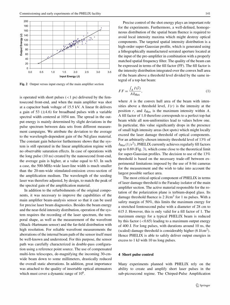
During 2006, most electrical tests in combination withchecks of the control and safety systems were performed.At the end of 2006, a first experiment was carried out us-ing the main amplifier section in a single-pass configuration,which resulted in (uncompressed) pulse energies of up to40 J. At the beginning of 2007, the final double-pass config-uration of the amplifier was commissioned, terminating thebeam on a calorimeter. The maximum pulse energy in ex-cess of 500 Joules obtained with 600 ps long pulses demon-strated the target value for the amplifier gain (100) at a ca-pacitor bank voltage of 18 kV. Following the installation ofthe large-aperture Faraday isolator and the subsequent trans-port beam line to the UNILAC experimental hall, the firstshots on target were successfully performed in May 2008.In this experiment, the precise and reliable synchronizationof PHELIX with the ion beam was demonstrated. The fol-lowing efforts were focused on the commissioning of thepulse compressor and the installation of the target cham-ber for laser-only experiments in the PHELIX building. Firstcompressed pulses were delivered to an experiment in Oc-tober 2008, with a pulse length of 700 fs and energies upto 100 J. A plot of the energy of the full system shots asa function of the main amplifier input energy is presentedin Fig. 2. The data correspond to the case when the system
Commissioning and early experiments of the PHELIX facility 141
Fig. 2 Output versus input energy of the main amplifier section
is operated with short pulses (<1 ps) delivered by the fem-tosecond front-end, and when the main amplifier was shotat a capacitor bank voltage of 15.5 kV. A linear fit deliversa gain of 53 (±4.6) for broadband pulses with a variablespectral width centered at 1054 nm. The spread in the out-put energy is mainly determined by slight deviations in thepulse spectrum between data sets from different measure-ment campaigns. We attribute the deviation to the averageto the wavelength-dependent gain of the Nd:glass material.The constant gain behavior furthermore shows that the sys-tem is still operated in the linear amplification regime withno observable saturation effects. In case of operations withthe long pulse (10 ns) created by the nanosecond front-end,the average gain is higher, at a value equal to 63. In sucha case, the 500-MHz-wide laser-line width is much smallerthan the 20-nm-wide stimulated-emission cross-section ofthe amplification medium. The wavelength of the seedinglaser was therefore adjusted, by design, to match the peak ofthe spectral gain of the amplification material.
In addition to the refurbishments of the original compo-nents, it was necessary to improve the capabilities of themain amplifier beam-analysis sensor so that it can be usedfor precise laser beam diagnostics. Besides the beam energyand the near-field intensity distribution, operation of the sys-tem requires the recording of the laser spectrum, the tem-poral shape, as well as the measurement of the wavefront(Shack–Hartmann sensor) and the far-field distribution withhigh resolution. For reliable wavefront measurements theaberrations of the internal beam path of the sensor itself mustbe well-known and understood. For this purpose, the sensorpath was carefully characterized in double-pass configura-tion using a reference point source. The use of compensatedmulti-lens telescopes, de-magnifying the incoming 30-cm-wide beam down to some millimeters, drastically reducedthe overall static aberrations. In addition, great importancewas attached to the quality of insertable optical attenuatorswhich must cover a dynamic range of 106.
Precise control of the shot energy plays an important rolefor the experiments. Furthermore, a well-defined, homoge-neous distribution of the spatial beam fluence is required toavoid local intensity maxima which might destroy opticalcomponents. The targeted spatial intensity distribution is ahigh-order super-Gaussian profile, which is generated usinga lithographically manufactured serrated aperture located atthe input of the pre-amplifier in combination with a properlymatched spatial frequency filter. The quality of the beam canbe expressed in terms of the fill factor (FF). The fill factor isthe intensity distribution integrated over the convex hull areaof the beam above a threshold level divided by the same in-tegral of a top-hat beam:
FF =∫A
I (�r)AIMax
, (1)
where A is the convex hull area of the beam with inten-sities above a threshold level, I (r) is the intensity at theposition r , and IMax is the maximum intensity within A.A fill factor of 1.0 therefore corresponds to a perfect top-hatbeam while all non-uniformities lead to values below one.In particular, this value significantly drops in the presenceof small high intensity areas (hot spots) which might locallyexceed the laser damage threshold of optical components.For an arbitrarily-chosen intensity threshold level of 13% ofIMax(1/e2), PHELIX currently achieves regularly fill factorsup to 0.69 (Fig. 3), which come close to the theoretical limitfor super-Gaussian profiles. The decision to use of the 13%threshold is based on the necessary trade-off between ex-perimental limitations imposed by the use of 8-bit camerasfor the measurement and the wish to take into account thelargest possible surface area.
The most critical optical component of PHELIX in termsof laser damage threshold is the Faraday isolator of the mainamplifier section. The active material responsible for the ro-tation of the polarization plane is terbium-doped glass. Itsdamage threshold fluence is 2 J/cm2 for 1 ns pulses. With asafety margin of 50%, this limits the maximum energy fora stretched femtosecond pulse with a diameter of 28 cm to615 J. However, this is only valid for a fill factor of 1. Themaximum energy for a typical PHELIX beam is reducedby this factor (<0.65) leading to a maximum output energyof 400 J. For long pulses, with durations around 10 ns, the(scaled) damage threshold is considerably higher (6 J/cm2).Hence PHELIX is able to safely deliver output energies inexcess to 1 kJ with 10 ns long pulses.
4 Short pulse control
Many experiments planned with PHELIX rely on theability to create and amplify short laser pulses in thesub-picosecond regime. The Chirped-Pulse Amplification

142 V. Bagnoud et al.
Fig. 3 Near-field intensitydistribution in the case of around (a) and elliptical (b) beamused in the long- and short-pulseexperiments, respectively. Thewhite contour line represents theconvex hull of the area used inthe fill factor calculation. Thefill factor compares to amaximum theoretical value of89% for the targeted beamshapes
(CPA) [14] is the standard technique used to perform thisand it is employed in the PHELIX system. In this scheme,the short laser pulses are temporally stretched before theamplification, such as to avoid accumulation of nonlin-ear effects during amplification. After final amplificationand just prior entering the interaction chamber they are re-compressed to their original duration. Particular to PHELIXare: first, the large stretching factor necessary to reach ahigh energy; second, the gain narrowing management nec-essary in a system that uses Nd:glass as a main amplificationmedium; and third, spatio-temporal effects originating fromthe amplification of large-diameter laser beams.
Large stretching factors can be reached using variousstretcher designs. Based on a design previously reportedelsewhere [1], the stretcher at PHELIX utilizes a 30-cm di-ameter primary mirror and one 1740 lines/mm grating usedat 72 degree incidence angle. The stretcher distance of 4 myields a stretching factor of 190 ps/nm and stretched pulsesof 2.3 ns duration. One requirement common to all stretch-ers is the excellent surface quality of the optics used in thesetup [15]. The stretcher at PHELIX utilizes spherical andflat mirrors with an optical surface quality better than λ/100in a root-mean-square (rms) sense. This is done so that thespectral phase error introduced by the stretcher stays wellbelow π and does not perturb the final pulse compression.The optical assembly of the stretcher is located on a trans-lation stage which allows an operator to easily adjust thepulse duration up to 20 ps using the motorized stage andpre-set positions. This offers many advantages over the stan-dard technique (adjusting the compressor grating-to-gratingdistance), which quickly becomes unpractical with gratingassemblies that weigh 100 kg. To characterize the stretcherand the femtosecond front-end in general, an auxiliary com-pressor using one 1480 lines/mm grating in a folded configu-ration has been used. Our calculations demonstrated that theresidual spectral phase, originating from mismatched grat-ing groove densities in the stretcher and compressor, is min-imal at pulse durations exceeding 100 fs as it is the case
Fig. 4 Single-shot autocorrelation measurement of the short pulse af-ter the auxiliary compressor (solid line) and theoretical autocorrelation(dashed line) calculated from the pulse spectrum
at PHELIX. As shown in Fig. 4, the pulse duration of theshort pulses generated by the femtosecond front-end can bere-compressed at durations close to their Fourier-transformlimit.
The second point which has to be taken into account isthe reduction of the spectral bandwidth of the laser pulse(known as gain narrowing) during the amplification. Whilethe first part of the amplification uses Ti:sapphire as a broad-band amplification medium at 1054 nm, the second part ofthe amplifier relies on Nd:glass, which seriously limits thewidth of the amplified pulse. A solution that mitigates thiseffect relies on the use of a birefringent filter [16] to shapethe spectrum of the laser such as to compensate for the gainnarrowing occurring in the system. The spectral filtering isdone between the two regenerative amplifiers so that the en-ergy losses induced by the filter are compensated in the sec-ond amplifier. After this stage, the spectrum shows a dip atthe central gain wavelength of Nd:glass, at a wavelength of1054 nm. At the end of the system, this dip is re-filled and

Commissioning and early experiments of the PHELIX facility 143
Fig. 5 Output spectrum of the laser pulse measured as it leaves themain amplifier. The spectral width is 5.3 nm FWHM and correspondsto a 370 fs Fourier-transform limited pulse. In the insert is a sin-gle-shot autocorrelation trace of the pulse at this particular shot. Be-sides large wings, the 490-fs autocorrelation FWHM is within 5% ofthe Fourier-transform limit
the effective spectral width is increased. Figure 5 shows theoutput spectrum of the laser when the birefringent filter isused. The width of the pulse spectrum does not exceed 3 nmFWHM when no pre-compensation is applied. But when thebirefringent filter is used, pulses with stable spectra in excessof 5 nm FWHM are typical for PHELIX on a daily basis.The effect on the Fourier transform limit of the laser pulseis important, reducing the pulse duration from values above600 fs to below 400 fs.
The spatio-temporal effects can have a relatively largeimpact on the pulse compression in a large-beam CPA sys-tem [17], and these effects require careful analysis of thepulse profile over the whole aperture of the beam. A com-plication to that is the need to perform the measurement dur-ing alignment with a few millijoules as well as on-the-shotwith several hundreds of joules. For this, we have developeda down-collimating system that not only adapts the beamsize to the entrance pupil of most measurement device butalso manages the energy delivered to the diagnostic packagewithout an excess of B-integral accumulation. A view of thesetup can be seen in Fig. 6. The diagnostic beam used forthis is the leakage through the diagnostic mirror, which wasmanufactured so that its transmitted wavefront is not only ofhigh quality but the transmitted wavefront of the first inter-nal reflection is also usable. This condition is fulfilled whenthe glass substrate is void of any defect and the surface pol-ished to a perfect flat. The interest lies in the fact that thebeam created by internal reflection in the substrate caries anenergy 4.5 × 10⁻⁴ lower than the main pulse energy andcan therefore propagate without a significant B-integral ac-cumulation through material. The pulse intensity is then fur-ther controlled using five partially transmitting plates that
can be remotely inserted into the beam. During the align-ment phase, only the direct transmission through the leakymirror is used. Both low-energy and high-energy channelsare recombined after the beam is down-collimated as shownin Fig. 6. Finally the diagnostic package uses a home-builthigh-dynamic-range single-shot cross correlator [18], that isused to cover the wide range of possible input energies. Herethe large dynamic range is used not so much to gather infor-mation with a high dynamic range but rather to ease opera-tion of the device that can then still tolerate a large variationof the input energy.
In addition to developing diagnostics and optimizing theshort-pulse profile, we also developed a series of pulse-control tools required for some experiment. The femtosec-ond front-end is hosting, for instance, a Mach–Zehnder in-terferometer that allows the creation of a pre-pulse of knownduration and energy. The pre-pulse duration can be set inde-pendently from the main short pulse using a small compres-sor located in one of the arms of the interferometer [19].Additionally, we use the fact that the compressor is usingtwo gratings in single pass to introduce a pulse front tilt tothe beam when necessary.
The last point concerning the temporal aspects of PHE-LIX deals with the temporal contrast of the laser pulses.Third-order cross-correlation measurements of the laserpulse show a typical pulse pedestal at the level of 10−6,most likely due to amplified spontaneous emission (ASE).This pedestal extends for up to 1 to 2 nanoseconds beforethe pulse. Particular to our setup was a large number ofpre-pulses originating from the cross-talk between the threelaser-cavities used in the front-end. The solution around thisproblem has been to isolate the short pulse oscillator and thesubsequent two amplifiers from each other using Pockelscells. In particular, a fast Pockels cell driver is used at theoutput of the femtosecond front-end to remove pre-pulseslocated 1 and 3 nanoseconds before the main pulse. As aconsequence, we cannot detect any pre-pulse with an en-ergy higher than 100 µJ, which is the detection limit of ourmeasurement scheme.
5 Cost-effective beam focusing
The final focusing optics assembly in a HEPW laser sys-tem is facing contradictory issues. On the one hand, the useof short pulses, which prevent from using transmission op-tics, requires that one employs a demanding off-axis opticalsystem. The solution based on the traditional polishing ofan optical substrate yields long-procurement times and ex-pensive pieces that are often unique. On the other hand, theconditions close to the target, at the time of the shot, areso harsh that the focusing optics is often damaged by debrisand secondary radiation, requiring its regular replacement orextra care for its use.

144 V. Bagnoud et al.
Fig. 6 Schematics of the short-pulse diagnostic beamline showing theenergy attenuation scheme. During the alignment phase, the beam di-rectly transmitted through the leaky mirror is used with an attenuatedenergy of 4 × 10⁻³. At the time of the shot, the beam generated by
internal reflection in the leaky mirror is used with an attenuated energyof 5×10⁻⁵. The beam combiner allows for easy use of one or the otherof the two beams while providing an additional attenuation factor. Thissetup keeps the B integral below 1 for pulses up to 500 J in 500 fs
Thanks to recent progress in diamond turning, we wereable to demonstrate that a diamond turned off-axis parabolamade of copper can be successfully employed for an ex-tended period of time in standard experiments. The advan-tages of a metallic mirror are manifold. First of all, thecosts and lead time for such optics is drastically reducedby roughly one order of magnitude. Second, the constraintsin geometrical arrangement possibilities offered by diamondturning are not these of traditional polishing. For instance, a90◦ large-aperture parabola is not more complicated to man-ufacture than a standard spherical shape, while the compli-cations met by traditional polishing techniques would nor-mally forbid such an optical arrangement. Other quadricsurfaces of any numerical aperture can also be conceivedfor an aberration-free imaging without much increase in themanufacturing complexity. And third, the use of metallicsubstrates offers the possibility to collect the back-reflectedlight over a large spectrum, allowing for additional targetdiagnostics opportunities in the visible and near infraredspectral bandwidths. However, the overall performance ofa diamond-turned piece of optics does not reach that of tra-ditionally polished ones and some trade-off have to be madein order to reach a performance compatible with the use in ahigh-energy laser system. In particular, the surface error andits roughness have to be mitigated.
We worked together with a company (Kaleido, Denmark)to develop a parabola suitable for our application. A featureof the surface is the periodic structure left by the tool dur-ing the machining process. This can be seen in the insert atthe top left of Fig. 7 that shows a measurement of a sam-ple on a microscopic scale. The period and amplitude of thesurface structure is determined by the machining speed anda surface roughness as low as 5 nm rms can be obtainedat lower machining speeds. The effect of the roughness isa spread of the energy out of the main central spot of thelaser. The amount of energy present in the central spot canbe easily estimated in the frame of the Fresnel diffraction,where the far-field energy distribution in the central spot isrelated to the Fourier transform of the disturbed wavefront,
Fig. 7 Calculated scattered energy as a function of the surface rough-ness for surfaces modeled using scaled periodic tooling imprints (upperleft insert) on the surface. The lower right insert is a measurement ofthe energy distribution at the focus of the parabolic mirror, showing a16 × 12 µm2 focal spot
taken at the origin. Figure 7 shows a plot of the estimated en-ergy losses due to surface scattering as a function of the sur-face roughness, using the hypothesis that the tooling marksscale with the surface roughness. As shown, energy losseswell below 5% can be obtained for values of the surfaceroughness well above the technical limits of the turning ma-chine.
In addition to tolerable scattering losses, the beams fo-cused by the copper parabola offer qualitatively good re-sults: the laser far-field distribution at the target chamberand that measured after the compressor using the com-pressor sensor package are showing similar shapes whenthe parabola is aligned to best focus. This indicates thatthe wavefront error introduced by the parabola is prac-tically negligible. Strehl ratio measurements of the farfield distribution of energy of the beam regularly showvalues at about 0.3, which is a good value consider-ing that no adaptive wavefront correction is necessary toachieve this goal. These measurements, together with ex-perimental evidence of high on-target intensities (see be-low), allow us to infer that diamond-turned final focusingsystems offer an interesting alternative to standard op-tics.

Commissioning and early experiments of the PHELIX facility 145
Fig. 8 Experimental set up forthe investigation of theinteraction of ions with laserdriven plasma
6 Experiments with ions and nanosecond pulses
A central line of research of the plasma physics group at GSIconcerns the interaction of energetic ion beams with plasmamatter. The unique combination of powerful laser systemsand an intense ion beam opens the possibility to investigatethe energy deposition and charge state distributions of swiftheavy ions penetrating laser generated plasma, a subject ofinterest for the astrophysics, inertial fusion or fundamentalresearch.
Earlier experiments, where ions were penetrating gas dis-charge or Z-pinch plasmas [20, 21] have shown a signifi-cant increase of both stopping power and mean charge stateof the projectile compared to the interaction with cold mat-ter. However, only few experimental data exist and they arelimited to low free electron densities (ne < 5 × 1019 cm−3)and low plasma temperatures (Tp < 20 eV). The GSI plasmaphysics group has dedicated its efforts to extend the experi-mental data base for the stopping power of ions in plasmasto higher densities and temperatures.
An important step to enable such experiments was thecompletion of the laser beam transport to the heavy-ion tar-get station Z6, a branch of the linear accelerator UNILAC atGSI. In 2008, first successful experiments exploited laser-generated plasma targets for interaction experiments withheavy ions. A new experimental setup, using PHELIX ad-ditionally to the already existing nhelix laser [12], has beenset up (see Fig. 8) and it quickly showed a significant im-provement in the quality of the measured data.
There, a thin foil, mainly a carbon foil with a thicknessof 0.5 µm, is irradiated by the PHELIX laser as well as thenhelix laser from both sides, transforming the foil into a
dense and hot plasma reaching densities of 1% of solid den-sity and temperatures of 100–200 eV. To keep the plasma ashomogeneous as possible for the ion beam, restricted to a500-µm diameter beam by a pinhole, a random-phase platelocated in the laser beam produces a 1-mm-large focal spotwith a “top hat” spatial intensity distribution. Under theseconditions, the plasma expansion in the central region isquasi one-dimensional during the first few nanoseconds. Inearlier experiments, where only the nhelix laser was irradiat-ing the foil from one side, the heating of the foil to a plasmastate was taking too long compared to the characteristic timeof the plasma expansion. Furthermore, the plasma was inho-mogeneous because of the microscopic inhomogeneities inthe laser intensity distribution of the focal spot generatedby a random-phase plate; and the ablation pressure pressedthe foil back for several hundreds of µm. The new set upusing PHELIX irradiating the foil from the opposite side of-fers several advantages: first, the foil is transformed to theplasma state faster; second, the very thin foil remains in thecenter so the ablation pressure differences from both sidesare reduced; and third, the inhomogeneity caused by the twophase plates are smeared out, resulting in significantly morehomogeneous plasma. As this plasma is expanding, densityand temperature gradients develop on both sides; and thesecharacteristics have to be experimentally measured, e.g., bylaser interferometry. At the same time, an ion pulse with alength of a few hundred µs, built up of micro bunches witha length of 3 ns FWHM and a frequency of 108 MHz, isprobing the plasma in a direction perpendicular to the ini-tial foil. This means the expanding plasma is being investi-gated each 9.2 ns. The relative delay between the laser andthe ion bunches can be shifted with an accuracy of 1 ns.

146 V. Bagnoud et al.
A time of flight measurement characterizes energy of theions penetrating first of all the cold foil, followed by denseand hot plasma, which is expanding and cooling down un-til all matter has vanished and the ions fly through vacuumwith their initial energy. Any change of the stopping power,as it occurs, e.g., when the laser heats up the target to theplasma state, can be detected as a deviation from the regular108 MHz periodic signal (see inlay in Fig. 8) [22]. A dipolemagnet behind the target chamber can be employed to mea-sure the charge state distribution of each single ion bunchafter exiting the plasma. As a result, we obtain a set of en-ergy loss data and charge state distributions of ions interact-ing with plasma. From these results, knowledge about thefundamental interaction mechanisms, like ion-energy depo-sition and ion-charge transfer reactions in plasma, can beobtained. To our knowledge, GSI is the only place world-wide where these kinds of experiments can be performed.
7 Experiments with short pulses: protons and X-rays
Using intense pulses of energetic heavy ions, plasma statesrelevant at the Earth center and inside giant planets likeJupiter can be prepared in the laboratory and probed by ad-vanced laser diagnostics. A central point of the research in-terest at GSI is the properties of WDM, which is a highlycoupled plasma state at close to solid density and temper-ature between 1 and 100 eV. Central questions like the lo-cation of critical states and phase transitions under such ex-treme conditions will be in reach of experiments. The roleof PHELIX is in this case to supply novel diagnostic ap-proaches using laser generated X-ray and particle beams.
Interaction experiments have been performed using thePHELIX facility as early as 2006. Since 2007, an exper-imental program involving national and international usergroups is established. These groups exploit the possibilitiesoffered by the experimental places in the X-ray laboratory,the laser bay and the Z6 experimental area.
One of the fields that receive attention in the PHELIXscience program is that of laser-generated soft-X-ray lasers.On the way to realization of soft X-ray lasers close to thewater window, a main obstacle is the high pump laser en-ergy required for the preparation of the lasing medium andthe complexity of the setup. In 2008, we demonstrated theconcept of the double-pulse pumping non-normal incidencegeometry that allows for a drastic simplification of the ex-perimental setup [19, 23]. Recently, we developed this elab-orate pumping scheme further, and we applied it to higherpumping energies in the framework of short-wavelength softX-ray lasers. For that, an optimized double-pulse structureis created in the front-end of the laser system, which thenpropagates collinearly through the amplifiers and the com-pressor and strikes the target under optimized non-normal
incidence. In that way, X-ray lasing is obtained at a lowenergy threshold while the complexity of the setup is dra-matically reduced. The optimized double pulse consists ofa 200 ps long pre-pulse that precedes the 1-ps long mainpulse by 130 ps. The laser beam is focussed to a line with10 mm ×20 µm FWHM, on a slab target under non-normalincidence of 17 degrees with a travelling-wave speed of 1.1times the speed of light, creating the transient collisionallyexcited gain for the soft X-ray laser transition. The focus-ing system consists only of one 90-degree off-axis copperparabola with a diameter of 300 mm and a focal length of1500 mm, producing the line focus via the aberration by the4 degree tilt off the normal off-axis incidence angle. Thetravelling wave is tuned by turning the second grating of thePHELIX two-grating compressor. One can show that a spa-tially dependent additional phase term is added to the pulse,meaning that the compression is not spatially uniform. How-ever, when the beam is large compared to the spectral spreadon the grating, the increase in pulse duration at the edge ofthe beam is minimal. For instance, a 0.17 degree grating tiltyields a 30 ps delay at the focus when a 12 cm beam isused, but at the non-detrimental expense of an increase inthe pulse duration by 250 fs on each side of the beam. Dur-ing the alignment phase, a test plate with two holes separatedby 10 mm is located at the target plane. The two beams arethen focused into a nonlinear crystal were second harmoniclight is generated. The two-pulse front-end is used at thispoint to control the amount of pulse-front tilt introduced bythe compressor. Practically, this corresponds to turning thegrating in the compressor until the delay, necessary for get-ting a signal, equals 30 ps or 15 mm on the delay stage ofthe two-pulse setup. Details about the experimental setupand traveling-wave calculation are beyond the scope of thispaper and will be presented in another publication.
We obtained lasing of Ni-like samarium X-ray laser at7.36 nm with a total pump energy as low as 36 joules [24].Figure 9 shows a measurement of the spectrum used as a sig-nature of the X-ray emission. The X-ray laser line is clearlyvisible in the first and second order of the spectrometer. Thisresult demonstrates the efficiency of the setup, as this pumpenergy is just half of the values required in previous ex-periments. This is an important milestone for applying thepumping scheme also for higher pumping pulse energies,which are necessary for reaching soft X-ray laser wave-lengths close to the water window. In addition, the reductionof the total pump energy now makes X-ray lasers also avail-able at this wavelength for high repetition-rate lasers like theLASERIX facility.
A key application of PHELIX in combined experimentsis to enable X-ray diagnostics of high-energy density statesof matter produced with intense heavy ion beams from GSIor FAIR. This requires multi-keV X-ray energies to pene-trate the dense plasma [25]. The development of laser driven

Commissioning and early experiments of the PHELIX facility 147
Fig. 9 Spectrum of a Ni-likesamarium X-ray laser obtainedwith a flat-field spectrometer.The lasing line at 7.36 nm isvisible in the first and secondorder of the spectrum
high-brightness fast X-ray sources is therefore a researchactivity that constitutes a key application of PHELIX. Thedevelopment of backlighter sources at GSI focuses on high-intensity short-pulse driven sources due to their favorablescaling to higher photon energies. When light is focusedonto matter to relativistic intensities, a large fraction of thelaser energy is converted into super-thermal electrons accel-erated to MeV energies. These electrons propagate throughthe target material and emit high-energy bremsstrahlungwhen scattering off target atoms. In addition they ionizestrongly bound inner-shell electrons of the target atoms giv-ing rise to characteristic line emission. High-intensity short-pulse-driven X-ray sources possess excellent characteristicsfor diagnostic purposes. The duration of the emission isclosely linked to the hot-electron relaxation and is on theorder of few picoseconds. Spatially, the emission is con-fined to the solid density part of the target. Using thin foilor wire targets, source sizes as small as 10 microns are re-alized, enabling high-resolution point projection radiogra-phy [26] with picosecond time resolution. In recent experi-ments at PHELIX, we have optimized a Cu K-alpha back-lighter source. Thin foils and wires with dimensions of fewtens of microns were irradiated, and K-alpha and hard X-rayemission was determined quantitatively as function of thelaser parameters pulse duration and focal spot size over awide range of focal intensities.
A variety of X-ray diagnostics/spectrometers is em-ployed in these experiments. A single photon counting cam-era gives a broad overview of the X-rays produced fromabout 5 keV to over 20 keV. The setup employs a cooledback-illuminated CCD camera (1024 × 1024 pixel) view-ing the target at a distance of about 3.3 m through a thinberyllium window. An evacuated pipe avoids absorptionin air allowing detection of X-rays below 10 keV. Filter-ing and distance are chosen to operate in the single pho-ton mode, so that on average less than 1 photon per pixelis detected. The device is absolutely calibrated using a ra-dioactive source. Post-processing selects single pixel events.A single detection-event probability of about 3% is deter-mined for the calibration energy (5.9 keV).
Figure 10 shows a spectrum obtained from a 100 J lasershot. Up to 1013 Cu K-alpha photons were generated pershot, corresponding to a conversion efficiency of laser en-ergy into line radiation of the order of 10−4, which is typical
Fig. 10 Spectrum of the copper K-shell emission obtained with thesingle-photon counting camera (top). Emission from higher chargestates up to He-like ions indicates strong heating of the target.High-resolution spectra of the K-alpha emission are obtained with theHOPG and mica (FSSR) crystal spectrometers (bottom)
for this class of experiments [27]. Besides strong K-alphaemission the spectra show K-beta and He-alpha radiationwhich can serve as a diagnostics of the target temperaturesreached [28]. Advanced X-ray scattering techniques [29] re-quire a higher spectral resolution to measure Doppler broad-ening [30] or to resolve plasmon resonances in the scatteringspectrum [31]. Low Thomson scattering cross-section ne-cessitates powerful sources and a high collection efficiency
148 V. Bagnoud et al.
of the scattering spectrometer. In favor for that purpose,highly oriented pyrolytic graphite (HOPG) crystals providean exceptionally high peak reflectivity [32]. At GSI weused a 70-mm large curved HOPG crystal in a van Hamostype spectrometer. Coupled with imaging-plate detectors,this constitutes a highly efficient spectrometer suitable forX-ray scattering diagnostics. The resolution is limited toE/�E ∼ 200 due to depth broadening and aberrations dueto the large mosaicity of the HOPG crystals. A much higherresolution can be provided by a focusing spectrometer thatemploys a spherically bent Mica crystal as focusing opti-cal element. In one direction of the imaging plane, the re-solving power of this spectrometer reaches 3000; and in theother direction, it provides in addition high-resolution one-dimensional spatial imaging (see, e.g., [33]), allowing forthe determination of the source size with a 10-µm accu-racy. The spectrum of hard X-ray bremsstrahlung was as-sessed using an 8-channel detector based on an imagingplate with lead filters of varying thickness up to 2 mm. Theresponse is simulated assuming a Boltzmann-type spectraldistribution and using the filter transmission and image platespectral sensitivity. We observe a strong dependence of thebremsstrahlung spectrum and consequently on the hot elec-tron temperature on the focused intensity. While in some ap-plications this background is detrimental, it is also a power-ful backlighter for radiographing macroscopic dense high-Ztargets.
Further experiments used the PHELIX laser system athighest intensities, around 5 × 10¹⁹ W/cm2. The intensityon target was measured using a novel nuclear pyrometry; acombination of selected isotopes is excited via (γ , xn) re-actions near the giant dipole resonance (GDR). Due to theenergy-dependent cross-sections, the bremsstrahlung spec-tra and therefore the electron distribution and laser intensitycould be confirmed. This diagnostics allows for measuringthe real on-target intensity regardless of the influence of pre-plasma conditions.
The interaction between an ultra-intense laser pulse (I >
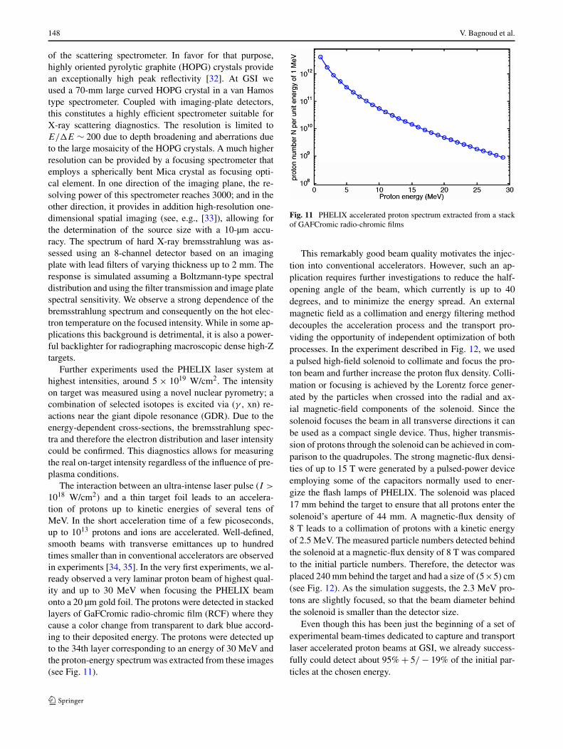
1018 W/cm2) and a thin target foil leads to an accelera-tion of protons up to kinetic energies of several tens ofMeV. In the short acceleration time of a few picoseconds,up to 1013 protons and ions are accelerated. Well-defined,smooth beams with transverse emittances up to hundredtimes smaller than in conventional accelerators are observedin experiments [34, 35]. In the very first experiments, we al-ready observed a very laminar proton beam of highest qual-ity and up to 30 MeV when focusing the PHELIX beamonto a 20 µm gold foil. The protons were detected in stackedlayers of GaFCromic radio-chromic film (RCF) where theycause a color change from transparent to dark blue accord-ing to their deposited energy. The protons were detected upto the 34th layer corresponding to an energy of 30 MeV andthe proton-energy spectrum was extracted from these images(see Fig. 11).
Fig. 11 PHELIX accelerated proton spectrum extracted from a stackof GAFCromic radio-chromic films
This remarkably good beam quality motivates the injec-tion into conventional accelerators. However, such an ap-plication requires further investigations to reduce the half-opening angle of the beam, which currently is up to 40degrees, and to minimize the energy spread. An externalmagnetic field as a collimation and energy filtering methoddecouples the acceleration process and the transport pro-viding the opportunity of independent optimization of bothprocesses. In the experiment described in Fig. 12, we useda pulsed high-field solenoid to collimate and focus the pro-ton beam and further increase the proton flux density. Colli-mation or focusing is achieved by the Lorentz force gener-ated by the particles when crossed into the radial and ax-ial magnetic-field components of the solenoid. Since thesolenoid focuses the beam in all transverse directions it canbe used as a compact single device. Thus, higher transmis-sion of protons through the solenoid can be achieved in com-parison to the quadrupoles. The strong magnetic-flux densi-ties of up to 15 T were generated by a pulsed-power deviceemploying some of the capacitors normally used to ener-gize the flash lamps of PHELIX. The solenoid was placed17 mm behind the target to ensure that all protons enter thesolenoid’s aperture of 44 mm. A magnetic-flux density of8 T leads to a collimation of protons with a kinetic energyof 2.5 MeV. The measured particle numbers detected behindthe solenoid at a magnetic-flux density of 8 T was comparedto the initial particle numbers. Therefore, the detector wasplaced 240 mm behind the target and had a size of (5×5) cm(see Fig. 12). As the simulation suggests, the 2.3 MeV pro-tons are slightly focused, so that the beam diameter behindthe solenoid is smaller than the detector size.
Even though this has been just the beginning of a set ofexperimental beam-times dedicated to capture and transportlaser accelerated proton beams at GSI, we already success-fully could detect about 95% + 5/ − 19% of the initial par-ticles at the chosen energy.

Commissioning and early experiments of the PHELIX facility 149
Fig. 12 Collimating effect of apulsed solenoid on ionsaccelerated by laser. Theradio-chromic film (RCF) stackis located away from the targetplane such that the amount ofparticle hitting it is notdetectable when the solenoid isnot pulsed (a). When the coil isenergized, a clear proton beamsignal (b) can be detected
8 Conclusion and perspectives
To summarize, PHELIX has demonstrated excellent perfor-mance in the high intensity operation mode as well as inthe long pulse mode, in a way that fulfills the needs of theresearch program at GSI. PHELIX offers opportunities forinternational users involved in a wide range of experimentsfrom the generation of high quality ion beams that can betransported through ion optical systems with high efficiency,to low-threshold X-ray laser emission at short wavelengthsand incoherent hard X-ray emission.
Near-term upgrades of the facility include the improve-ment of the temporal contrast of the laser pulses, frequencydoubling for long-pulse operation in order to avoid back re-flections, the development of tight focusing capabilities atthe UNILAC experimental hall for hohlraum heating, andfinally the installation of a short pulse beamline of a some-how reduced power (100 TW) at the accelerator, in order tocouple laser-accelerated particles into conventional acceler-ator structures.
These projects as well as the research program at PHE-LIX will also benefit from the newly funded Helmholtz In-stitute Jena (HIJ), whose goal is to promote research at theinterface of particle accelerators and high power lasers. Thescope of the institutes includes challenging projects in basicresearch such as strong field QED and WDM, both stronglyrelated to the realm of extreme states of matter. It also dealswith the laser technology relevant to high power lasers inthe context of the FAIR and XFEL projects and it offers thescientific environment necessary to keep the performance ofPHELIX in phase with the ever-increasing experimental re-quirements.
Acknowledgements The successful completion of PHELIX andquality of operation depended on a number of very different valuablecontributions. Basis for the whole project was the endowment of ex-pensive large diameter laser components from the former Nova andPhebus systems by DOE and CEA. In this matter, our sincere thanks goto J. Caird, M. Campbell, R. McKnight, G. Logan, and M. Perry, and A.Bettinger, M. Decroisette and F. Kovacs. We also thank D. Habs (LMUMünchen), F. Krausz (MPQ München), W. Sandner (MBI Berlin) andR. Sauerbrey (FZD Rossendorf) for their contributions. Important laserdevelopments and access of European researchers was supported by theEuropean International Infrastructure Initiative Laserlab Europe.
Open Access This article is distributed under the terms of the Cre-ative Commons Attribution Noncommercial License which permitsany noncommercial use, distribution, and reproduction in any medium,provided the original author(s) and source are credited.
References
1. M.D. Perry, D. Pennington, B.C. Stuart, G. Tietbohl, J.A. Britten,C. Brown, S. Herman, B. Golick, M. Kartz, J. Miller, H.T. Powell,M. Vergino, V. Yanovsky, Opt. Lett. 24, 160 (1999)
2. C.N. Danson, P.A. Brummitt, R.J. Clarke, J.L. Collier, B. Fell,A.J. Frackiewicz, S. Hancock, S. Hawkes, C. Hernandez-Gomez,P. Holligan, M.H.R. Hutchinson, A. Kidd, W.J. Lester, I.O. Mus-grave, D. Neely, D.R. Neville, P.A. Norreys, D.A. Pepler, C.J.Reason, W. Shaikh, T.B. Winstone, R.W.W. Wyatt, B.E. Wyborn,IAEA J. Nucl. Fus. 44, S239 (2004)
3. E.W. Gaul, M. Martinez, J. Blakeney, M. Ringuette, D. Hammond,A. Jochmann, R. Escamilla, T. Borger, G. Dyer, T. Ditmire, inConference on Lasers and Electro-Optics/International QuantumElectronics Conference, OSA Technical Digest (CD) (Optical So-ciety of America, 2009), paper JWB2
4. E.I. Moses, R.L. McCrory, D.D. Meyerhofer, C.J. Keane, Opt.Photonics News 20, 42 (2009)
5. http://www.fair-center.org

150 V. Bagnoud et al.
6. HEDgeHOB Collaboration, Technical report for the HEDge-HOB collaboration experiments, in FAIR Base-line Techni-cal Report, ed. by H.H. Gutbrod (GSI, Darmstadt, 2006), orhttp://hedgehob.physik.tu-darmstadt.de
7. WDM Collaboration, Radiative properties of warm dense mat-ter produced by intense heavy ion beams, in FAIR Base-line Technical Report, ed. by H.H. Gutbrod (GSI, Darmstadt,2006), or http://www.gsi.de/forschung/phelix/Experiments/FAIR/WDM/index_e.html
8. R. Bock, S. Borneis, Ch. Bruske, J. Caird, D. Habs, D. Hoffmann,H. Kluge, Th. Kühl, D. Marx, P. Nickles, M. Perry, M. Roth, W.Sandner, W. Seelig, A. Tauschwitz, in Inertial Fusion Sciencesand Applications 99, ed. by C. Labaune, W.J. Hogan, K.A. Tanaka(Elsevier, Paris, 2000), p. 703
9. D.H.H. Hoffmann, A. Blazevic, P. Ni, O. Rosmej, M. Roth, N.Tahir, A. Tauschwitz, S. Udrea, D. Varentsov, K. Weyrich, Y.Maron, Laser Part. Beams 23, 395 (2005)
10. Th. Stöhlker, H. Backe, H.F. Beyer, F. Bosch, A. Bräuning-Demian, S. Hagmann, D.C. Ionescu, K. Jungmann, H.-J. Kluge,C. Kozhuharov, Th. Kühl, D. Liesen, R. Mann, P.H. Mokler, W.Quint, Nucl. Instrum. Methods B 205, 156 (2003)
11. http://www.laserlab-europe.net/12. G. Schaumann, M.S. Schollmeier, G. Rodrigez-Prieto, A. Blaze-
vic, E. Brambrink, M. Geissel, S. Korostiy, P. Pirzadeh, M. Roth,F.B. Rosmej, A.Ya. Faenov, T.A. Pikuz, K. Tsigutkin, Y. Maron,N.A. Tahir, D.H.H. Hoffmann, Laser Part. Beams 23, 503 (2005)
13. D. Beck, K. Blaum, H. Brand, F. Herfurth, S. Schwarz, Nucl. In-strum. Methods 527, 567 (2004)
14. D. Strickland, G. Mourou, Opt. Commun. 56, 219 (1985)15. V. Bagnoud, F. Salin, J. Opt. Soc. Am. B 16, 188 (1999)16. C.P.J. Barty, G. Korn, F. Raksi, C. Rose-Petruck, J. Squier, A.-C.
Tien, K.R. Wilson, V.V. Yakovlev, K. Yamakawa, Opt. Lett. 21,219 (1996)
17. H.-M. Heuck, P. Neumayer, T. Kuehl, U. Wittrock, Appl. Phys. B84, 421 (2006)
18. D. Javorková, V. Bagnoud, Opt. Express 15, 5439 (2007)19. D. Zimmer, B. Zielbauer, V. Bagnoud, U. Eisenbarth, D. Ja-
vorkova, T. Kuehl, Opt. Express 16, 10398 (2008)20. D.H.H. Hoffmann, K. Weyrich, H. Wahl, Th. Peter, J. Meyer-ter-
Vehn, J. Jacoby, R. Bimbot, D. Gardès, M.F. Rivet, M. Dumail, C.Fleurier, A. Sanba, C. Deutsch, G. Maynard, R. Noll, R. Haas, R.Arnold, S. Maurmann, Z. Phys. A 330, 339 (1988)
21. J. Jacoby, D.H.H. Hoffmann, W. Laux, R.W. Müller, H. Wahl,K. Weyrich, E. Boggasch, B. Heimrich, C. Stöckl, H. Wetzler, S.Miyamoto, Phys. Rev. Lett. 74, 1550 (1995)
22. A. Blaževic, V. Bagnoud, S. Borneis, U. Eisenbarth, A. Frank, J.Fils, S. Götte, M. Günther, T. Hahn, T. Heßling, M. Kreutz, S.Kunzer, J. Menzel, T. Merz-Mantwill, E. Onkels, A. Pelka, D.Reemts, O. Rosmej, M. Roth, M. Schollmeier, D. Schumacher, T.Stöhlker, A. Tauschwitz, H. Wahl, K. Witte, in GSI Annual Report2008, Plasma-Physics-02 (2009), p. 315
23. D. Zimmer, V. Bagnoud, B. Ecker, U. Eisenbarth, J. Habib, D.Hochhaus, D. Javorkova, S. Kazamias, T. Kuehl, D. Ros, D. Urs-escu, B. Zielbauer, Springer Proc. Phys. 130, 91 (2009)
24. D. Zimmer, V. Bagnoud, B. Ecker, D. Hochhaus, T. Kuehl, D. Ros,B. Zielbauer, B. Aurand, in Ultrafast Optics Conference, Arca-chon, France (2009), paper p.2.25
25. N.A. Tahir, I.V. Lomonosov, A. Shutov, V.E. Fortov, M. Geissel,A.R. Piriz, C. Deutsch, D.H.H. Hoffmann, Nucl. Instrum. Meth-ods A 606, 128 (2009)
26. E. Brambrink, H.G. Wei, B. Barbrel, P. Audebert, A. Benuzzi-Mounaix, T. Boehly, T. Endo, C. Gregory, T. Kimura, R. Kodama,N. Ozaki, H.-S. Park, M. Rabec le Gloahec, M. Koenig, Phys.Plasmas 16, 033101 (2009)
27. H.-S. Park, D.M. Chambers, H.-K. Chung, R.J. Clarke, R. Eagle-ton, E. Giraldez, T. Goldsack, R. Heathcote, N. Izumi, M.H. Key,J.A. King, J.A. Koch, O.L. Landen, A. Nikroo, P.K. Pate, D.F.Price, B.A. Remington, H.F. Robey, R.A. Snavely, D.A. Steinman,R.B. Stephens, C. Stoeckl, M. Storm, M. Tabak, W. Theobald,R.P.J. Town, J.E. Wickersham, B.B. Zhang, Phys. Plasmas 13,056309 (2006)
28. W. Theobald, K. Akli, R. Clarke, J.A. Delettrez, R.R. Freeman, S.Glenzer, J. Green, G. Gregori, R. Heathcote, N. Izumi, J.A. King,J.A. Koch, J. Kuba, K. Lancaster, A.J. MacKinnon, M. Key, C.Mileham, J. Myatt, D. Neely, P.A. Norreys, H.-S. Park, J. Pasley,P. Patel, S.P. Regan, H. Sawada, R. Shepherd, R. Snavely, R.B.Stephens, C. Stoeckl, M. Storm, B. Zhang, T.C. Sangster, Phys.Plasmas 13, 043102 (2006)
29. S.H. Glenzer, R. Redmer, Rev. Mod. Phys. (2009, to be published)30. S.H. Glenzer, G. Gregori, R.W. Lee, F.J. Rogers, S.W. Pollaine,
O.L. Landen, Phys. Rev. Lett. 90, 175002 (2003)31. S.H. Glenzer, O.L. Landen, P. Neumayer, R.W. Lee, K. Widmann,
S.W. Pollaine, R.J. Wallace, G. Gregori, A. Höll, T. Bornath, R.Thiele, V. Schwarz, W.-D. Kraeft, R. Redmer, Phys. Rev. Lett. 98,065002 (2007)
32. M.K. Urry, G. Gregori, O.L. Landen, A. Pak, S.H. Glenzer,J. Quant. Spectrosc. Radiat. Transf. 99, 636 (2006)
33. A.Ya. Faenov, S.A. Pikuz, A.I. Erko, B.A. Bryunetkin, V.M.Dyakin, G.V. Ivanenkov, A.R. Mingaleev, T.A. Pikuz, V.M. Ro-manova, T.A. Shelkovenko, Phys. Scr. 50, 333 (1994)
34. T.E. Cowan, J. Fuchs, H. Ruhl, A. Kemp, P. Audebert, M. Roth,R. Stephens, I. Barton, A. Blazevic, E. Brambrink, J. Cobble, J.Fernández, J.-C. Gauthier, M. Geissel, M. Hegelich, J. Kaael, S.Karsch, G.P. Le Sage, S. Letzring, M. Manclossi, S. Meyroneinc,A. Newkirk, H. Pépin, N. Renard-LeGalloudec, Phys. Rev. Lett.92, 204801 (2004)
35. F. Nürnberg, M. Schollmeier, E. Brambrink, A. Blaževic, D.C.Carroll, K. Flippo, D.C. Gautier, M. Geißel, K. Harres, B.M.Hegelich, O. Lundh, K. Markey, P. McKenna, D. Neely, J.Schreiber, M. Roth, Rev. Sci. Instrum. 80, 033301 (2009)