combustion characteristics of waste fuels in a fluidized bed · 2002-08-22 · 523 hwahak konghak...
TRANSCRIPT

HWAHAK KONGHAK Vol. 40, No. 4, August, 2002, pp. 523-528
��� ����� �� ��� ��� � �� �� ��
�����������†
������� ����(2002 3� 31� �, 2002 6� 18� ��)
Combustion Characteristics of Waste Fuels in a Fluidized Bed
Jin Hwan Choi, Sang Deuk Lee and Sang Min Choi†
Department of Mechanical Engineering, KAIST, Daejeon 305-701, Korea(Received 31 March 2002; accepted 18 June 2002)
� �
���� ���� �� �� ��� ���� �� ��� ��� �� ��� �� ��� �� �� ��
�� ���� � �� ! "# $% &'�(. ) �* +,- �� �� �.� /0� 12 �� 34 56� 789
��� :;�� <��� =�(. �� ��� >�?/�� 34@ AB,C� DE�� F? GHI JB 789 KL�
� MNO 789 ��DP@ QR�S�, � TU� �V�W �. NO� XY ��@ :Z�S(. �* �[ �.� \],
G^ _`^, �a _`^ bc� �� Qd �.� e��S(. fg(700oC)C� 7^h� 789 ���� ̂ i� a cm
�. NO� jN�S(. �� XY k �l[C� mnh� CO, CxHy, CO2 op� ��A n*�� �q,C� r��
W XY 34@ ��, s ��� *��W t�S(. �.� a�uv 56� �� ��� wU� xy@ z{�|�, N
O� }�� XY� wU� xy@ <�uC�~ NO� }�� ��� �? H�^� ��� t�S(. AB,C� t
I �.� �� 34� 789 ��� "#� �� �w� <��� �� 34@ ��� �� ��@ GJ�S(.
Abstract − The information on the processes of volatile combustion and devolatilization is important in designing and oper-
ating the combustor of solid waste fuels of which volatile proportion in the combustible is very high. The aims were to com-
pare the reactions of the waste fuels having different origin and to sort out their own distinguishable characteristics that are
important in designing the FBC(fluidized bed combustor). Waste fuels were selected to examine their characteristics of pyrolysis
and combustion in a laboratory scale combustor in which a nearly single particle combustion condition was reproduced. Wood,
paper sludge, sewage sludge and RDF were selected and the fuel particles whose characteristic lengths were a few centimeters
were injected into a fluidizing environment of 700oC sand in the thermally maintained reactor. By introducing some experimental
parameters such as the rate and the fraction of carbon conversion, the combustion characteristics of the fuels were checked for thetwo separated processes of devolatilization and char combustion. Additional experimental work was carried out to determine the
influence of the high water content of sludge fuels on its combustion process. The comminution effects on the combustion process
of the large fuel particle were rechecked by performing the experiments for the wood particles of various size. The meanings of the
fuel combustion characteristics in designing of FBC were checked and some design strategies were suggested.
Key words: Devolatilization, Solid Waste Fuel, Char Combustion, FBC
1. � �
��� ��� �� �� ��� ����� ��� ��� �
�� ��� �� �� !�. "� #$ �%� ������ &'
(� )*+ , -.� / 012�3 4 567 8 9��:�
;<=� ��� ����� >?@ AB@C� �D�� !�[1, 2].
��� &'��� �D EF ���G HIJ (� ��� K �
G LM NO !� PQ� RS@T &' UAC� VW2X !�.
� Y�� ZC� / ����[ \ �� ]^� ;<=� ���
���� �_(V &'` aC� bcd�[3].
X9 ��� 3� ����� e<, fg ���� hi K ��[
Rj ��(�. X9 ��� kl, -.� \X ,�m n,� -
. ��� op LM q�� ;�� a� rs��. ��� ��tu
v X9 ���� �� rt3 ��� op LM q�� ;�� PQ�
��� ��� wx� !)� ���� X�� �� rt Rj yz
� B;��[4, 5].
2{|2 ��� } X9 ��� �� ~�� U� ��[ ���(†To whom correspondence should be addressed.E-mail: [email protected]
523

524 �����������
M ��)��C� r� �� U� �� ��[ /� �;=) !�.
�b� ����� X9 ��� �� rt� U� �I[ �� � B
�=) !Cm ��� ��� ����� ��tG ��(� �� �
x� ;V ��[4]. � ��� �@ ��� �� ���� X9 ��
�� �,I/�� rtG ��@C� ��(V ��� X9 ��� �
�� �� rtG >?-C�� ���� ��� o� U�@T rs
G �,I }X ���� �� rt� ��� ��� ��� ¡�
�¢G £[(� a��.
2. �� ��� �� ��� ��
Fig. 1� ��� ��� wx �� wB� !)� ¤z� ��� rt
7 �¥ �x� 3F@C� m¦}§�.
��� wx� !)� ��@C� ¨=� � © �ª B« �� ¬
� , © eg , K'X l�. B ®7[ ��d�. � 7B�
� e�>� ¯° �� ±²., �� e�., ��� ��( ³G ®B
(� , -�.� \ 012� ´� l�.� µ ��� ���
� ¶j ;� �� ·_.�m ��^G ®B��.
��� ���� LM ¸¹� º';¹� m»)2� ¸¹�� ��
� ��7B� ¼¨=X º';¹�� kl, ½� �� >«d [�
t �ª� 2q ��[ ��)¼�. \ �� ]^7 �eI ¾¿� �
�� ���� wx(X +b(� �� [< yz� ·À� (m� ¸
¹/º';¹ Á3� �2 �'��. wx Âx�� @B Á3� wB(
*$ ¸¹� º';¹ �Ã� U� ±² ��� ��^G ®B(V �
© �ª B«G IÄ ��. K1m ±²d ��� �� rt� �Åd
B;[ Æ� �Ç�� È �Ã� �� �(� ®B(� a ÉÊ(�.
��� wx 7B�� �� rt� �I ®Bd �,I Ë3 © ��^
G @_(V ¸¹� º';¹ ���� � © �ª B«F#G ®6Ì
!C� �� ´ wx Íq y� ÎÏ� =� �, ��� ¸¹
�� º';¹� EÐ=� �,� �G ®B(� a��. kl,
¸¹Ñu ÒÓp º';¹��3 ��=� ��^ ��J Ë3, ̧ ¹
��� «� f3, Á3 ³7 ´ ��� +b ��� op Ôp¼�.
kl,� >y� \ X9 ���� ¶j� kl,� ¸¹/º';¹
��^G ®B(� a� ÕÖ yzI¼�. ��� wx� !)� ¸¹/
º';¹ Á3� wx ��� ¯° �2(� �I�� ��� ���
kl, -., ×kl Ë3, kl, �� 7B� U� B;[ ¤ @��.
3. ���� � ��
3-1. ����
�� <¡� Fig. 2� ´� 2Ø 100 mm �ÙTÚ� �C� u#)
¼ \� 1,100 mm� ¬Û ��� �����. ��� ¸¹� £Ü 2
Ø� 550µmT ÝÞ� ��)ßC� \�� 200 mm�X à� ��J
Ë3� �Á�� 0.15 m/sec��. ��� ���� ��J [�� á�
[��� [�(V ��� }�� Á3� OB(M �2Ì !3â
wx(ã�. ��[�� ��� Ð��� �Ë@C� äå=) , �
�� f3 B� ��)¼�. CO� CO2 [� B�� >,« @á
æç f3 B�, �J �(Hydrocarbon, CxHy)� Jè �ÁJç f3
B�, «�� ¶j ��tç B�[ �_d�. , ��� ÐSd
é¥� ��� êë ��� �I ìí�� �<d�.
3-2. ����
¸¹ Á3[ 700oC� �2=� ��� îÝ ��� ���� X9 �
� ²�� ÂO ½� ¾ Â�(�� 5 g� I�=� ��.)� ���
±²(X �:� o� ��[�(CO2, CxHy, CO, O2) B ®7� ÛI
� X9 ²�� �,I, �� 7BG ��(ã�. ��J [��� e�
� ·_ïC� �,I 7BG ��Ì P�� e� Ué ª�[�� �
�J [�� ·_(V ²�[ 9�(� ¸¹�� H«� ,��� �t
(ã�[6]. Fig. 2� ��d a7 ´� º';¹�� «�(20 Nl/min)�
ð²(V � 7B�� lñd �,I ñt�(kl,)G ���ò�.
H«� ,��� �,I �� ���� ×kl 7B ó� ô õ�
×kl 7B� öm� �Y� ��J [�� ª��� e�� b÷(
V ���ò�. ×kl 7B� öm� �Y O«J�� ½� �«J
��� lñ� Õ �� m¦m2 ø� �YC� æBï�. � EçC�
×kl 7B7 õ �� 7BG ,'I� ��Ì [ !§�.
Bd CO2, CxHy� CO f3� �_(V ��d ��.G x«(
Fig. 1. Schematic diagram for the relation between fuel properties and FBC design parameters.
���� �40� �4� 2002� 8�

�� ��� ��� �� 525
ãC� �aC��� �� b÷ Ë3(rate of carbon conversion, 1/sec),
�� n ^(carbon recovery, %)7 £Ü �� b÷ �:(mean carbon
conversion time, sec) ³G x«(ã�. �# T�� Table 1� B'=
) !C� �ù� I Eç7 �x� �b� l�d úQ� û�=§
�[7-9].
3-3. ��
� ����� �� U� X9 ��� ���� mH, �û ��� �
���� ��=� ( 012, û2 012, K'X üý(pellet)C�
tþd RDF(refuse derived fuel)� äÿ(ã�. Table 2� U� ���
�� , ®7� m¦}§�. mH� B�$9(2×2×2 cm), RDF� ¬
��(2Ø 2 cm, \� 2 cm)� þÇ�� 012� 2Ø� 2 cmT �)
' þÇ� �iß�. U� ��� [�, y kl, -. 85%- 88%
� Rj \�. õ� [� t,G ��� [B(X ¬� , ®7� �
_($ b9 ��. y kl,� -�d ��.� "Ì !�. m
H 70%, ( 012 68%, û2 012 68%, RDF 79%� ��[ k
l, y� %�(� aC� x«=§�.
4. �� �
4-1. �� �
²�� L�[ cmT >?@ � X9 ��� ��7B�� ²��
,� 7B Rj yz� ÃÌG ��[10]. ��� ��� �G Û
I ²�� �7 ,� 7BG ��(ã�. mH� ��d ( 012
� ¶j õ ��� ¾� ²�� m»)� ¼¨=� ��d û2 0
12� ��[ �H'` P|2 �� ²� þ�G �2(ã�. �$�
RDF� �J ó �) � ²�� ��� ¦� aG ��Ì [ !
�. �� ��� ��M ��d û2 012� ( 012� �� ó
��� ¸¹� ²� þÇ� n,G ô8�. û2 012� n, ²��
±² �� �Þ� þÇ� �2(X !C� ( 012� ¶j� ¾
� � ²�� �¾¼ þÇ[ =§�.
4-2. ��� ��� �� �� �� ��
�� U�� d 4[2 ��� UI ��J [�� e�� � �� �
� �� ®7� ª�� b÷(V ¸¹�� ��� �û� �,I ��
�� ®7� Fig. 37 Table 3� m¦}§C� 3n �� ��� ®7�
£Ü��.
�� n ^ e�� ð²� ¶j Ý� ��� UI 90% �� 3Ô
(ãC� � ®7� e�� ð²� ¶j X9 �� ²�� ±²d U�
,� ��[ [��� �� [�(CO, CO2, CxHy)� �Ð=) [� ,
��� �I n d aG � ��. K1m ��J [�� ª� [
�� ��$ kl,� ��=� �à º';¹� «� ð²����
��� �|2�=) ��� } kl,� 9��:� �Ҽ�.
��� Ð��� Á3[ µX �� �:� �,(2 ø� PQ�
� �� ��� lñ(V �� n ^� Table 3� ®7� ´� �� �
� ����;� µM m��.
Fig. 3(a)� ×kl 7B�� õ ��� b÷=� �YG J��� �
Fig. 2. Lab-scale fluidized bed combustor.
Table 1. Equations for the determination of the parameters(CCxHy is measuredon CH4 base)
Experimental parameter Definition
Rate of carbon conversion(sec−1)
Fraction of carbon conversion(%)
Mean carbon conversion time(sec)
Carbon recovery(%)
Amount of carbon burnt up to specific time t(n), and total carbon burnt(N)
ddt---- n
N----
QN---- CCO CCO2
CCxHy+ +( )=
f nN---- 100 %( )×=
tc 1 nN----–
o
tB∫ dt=
C_Rec Ncarbon in fuel----------------------------------- 100 %( )×=
carbon in fuelf c mfuel×
12--------------------=
n Q CCO CCO2CCxHy
+ +( )dt0
t∫=
N Q CCO CCO2CCxHy
+ +( )dt0
tB∫=
Table. 2 Results of ultimate analysis, proximate analysis and calorimetric analysis of the fuels
FuelsWater(%)
HHV(cal/g)
Dry base
Combustible (%) Ash(%)C H O N S Volatile Char Sum
Wood 6 4,200 49.8 5.2 44.5 <.01 <.01 85 15 100 <.1Sewage sludge 74 2,100 17.6 3.0 14.6 2.8 <.01 32 6 38 62Paper sludge 57 2,400 27.9 4.2 27.9 0.4 <.01 50 9 59 41RDF 4 5,600 51.2 7.6 23 1.4 <.01 72 11 83 17
HWAHAK KONGHAK Vol. 40, No. 4, August, 2002

526 �����������
�(ãC� �a� U� w� � l�d úQ� �ù� ��§�
[7]. ��� ��t� op � �� �: ��2u �� b÷� Ý�
È [2 þÇ� �,` !�. Fig. 3(a)�� mH� ��d 01
2� ×kl 7B7 õ �� 7B� ��� �,=� �·� ¶¢G ;
�m, RDF� õ ��� I�(� �:� �� M m¦m2 ø� a
G ! !�. RDF ²�� ¶j� È 7B� ��� y"=) O)m
X !�. ²� ,� rt� �� 7B� ®B@T ÃÌG � aC� #
Âd�. kl, -.� �U@C� \C� $M ��2X %ÜO� L
�� / õ ²�� ��2� t¢� � RDF� ¶j ù(M �
�¼ ²�� u#) &C�� ��� Rj '�M ¼¨d�. ��¼ ²
�� � �_.7 ²�� �(� >I � �$@ \ [� Ë3�
«� �« Ë3� ;<(� PQ� ×kl, õ �� 7B ÝÈ[ '�
M ¼¨d�. ®7@C� $M ��2� �� ²�� ¶j ×kl 7B
7 õ �� 7B� �,� ��(M m¦m2 ø��.
4-3. ��� �� ����
Fig. 3(b)� ®7� Z Í�� w�� �,I �� ���� ��� ®
7��. ��J [�� ª�� ·_� ×kl 7B7 e�� b÷� �
)� õ �� 7B� ��(M �,=� aG ! !�. $M ���
õ ��[ '�M ¼¨=) ×kl 7B7 õ �� 7B� �,� )*
*+ RDF� ¶j�3 È 7B� ��(M �,=X !�. �� ���
� ��� ®7� >?(V ×kl 7B�� �� b÷� þÇ� LM
q�� ;�2 ø��.
�� b÷ Ë3��� , !� ×kl Ë3� H«� ÷¶�� �
� ��� ��� ��� op LM ��2 ø aG �TÌ !�.
Fig. 3(b)�� �� ��� 100� �A� ×kl 7B� Ý�7 Ë3[
û2 012� ûá� m-2 ��[ ÝÈ >.(M m¦mX !�. ×
kl 7B� UI x«d £Ü�� b÷ �:� 102-129�� ��� �
�� op LM q� m2 ø��. ²�� þÇ[ �2=� ��d û2
012� ¶j� ²� }��� ×kl 7B� �I lñd kl,� È
/+ n,�G Û7IÄ (� PQ� ×kl 7B� V1 �DC� ��
2� �� ��� >?(V 0'M ¼¨=� aC� #Âd�. K1m õ
�� Ë3� �� �: ��� op �� ,� rt PQ� LM Ôp
2� a� �Td�. õ �� Ë3� $M ��2� RDF� ¶j[ [<
\X ²�� þÇ[ �2=� ��d û2 012� ¶j� [< µ�.
4-4. �� � ! �"
Z Í� �� ®7�� ²�� L�[ 2 cm� � ¶j ²�� ,�
]7[ ��t� �¢G ð� aG , !§�. ×kl 7B �ó�
3 ²�� þÇ[ >?@ 1 �2=� mH ��� L�� 2J�3 ²
� L�[ ��� ¡� �¢G ��@C� �4;5�. Fig. 4� mH
²�� L�� 1, 2, 3 cm(2� 6�)� 2J�3[$� ��� ®7�
�[8]. ²�� L�[ �G â '�M [�=� PQ� �� Ë3[ 7
[(� aG �� b÷ Ë3��� , [ !�.
Table 4� ®7�� ²� ·�8[ �G P mH� ¶j �� n ^�
9)2� a ×kl Ë3� 7[[ ���� �� �:^G 2m¡M \
V � �� ��G OCò� PQC� #Âd�. �� £Ü �� �:C
��� L�[ ;2$� �� �:� 7[(� ¶¢G ��(M ! !�.
4-5. #$%� &� '( )*��
012�� , -.� \Ò l�.� µ� PQ� ;� ��� -
< ��=m ���� ±²(� b ����� ��d�. 012�
, -.� o� �� rt 012� ��� ��� wx� !)�
yz(�.
Fig. 3. Fraction and rate of carbon conversion: dry wood, paper sludge, RDF, sewage sludge, Tbed 700oC, flow rate 120 Nl/min(0.86 m/sec), size : 2 cm,fluidization gas : N2, air.
Table 3. Carbon recovery(%), mean conversion time tc(sec)
Case Wood Sewage sludge Paper sludge RDF
Combustion environment Air Fig. 3(a)
T(oC) C_Rec. tc C_Rec. tc C_Rec. tc C_Rec. tcTotal 95 113 91 134 92 192 97 93
Pyrolysis N2→air Fig. 3(b)
Total 85 151 89 186 90 249 89 124Volatile 59 115 51 102 50 129 75 118
Char 26 36 38 84 41 120 14 6
���� �40� �4� 2002� 8�
�� ��� ��� �� 527
Fig. 5�� �� Ë3� m¦}� �� b÷ Ë3� ;$ ±² ���
� , �� 7B� ²�� [�G 2��=� PQ� , -.� /
Òª â K >� 9)2� a� ��d�. 012 ²�� , -�.
� 50% ��C� \Ò2$ ?3[ @I� , �� 7B�� ²��
þÇ[ �2=2 A(X ,�=� PQ� �� Ë3� , -.� \
¶j� B�* Cp¼�. , -.� ²� þÇ� DÐ !� �
x� E)�$ $M ��� RDF� ´ þÇ� �� 7B� ¼¨=�
aG , !�. �� £Ü b÷ �:G ;$ ,-.� 7[($�
F)m�[ �� N)¹� aG Table 5�� �TÌ !�. ,-.
� \ ¶j�� ²�� ,�[ 012� �� 7BG 2�(� aG
, !�.
���� ±²d � ²�� �� © ×kl 7B�� ,7 kl,
� '�m[$� ñ8 }� �GÚ�� �I ,�d�. õ �� 7B�
� ×kl 7B �ó å@I¼ ²�� ��·�� HI� �I � ²
�� ,�d�. ,� 7B ²�� L�� N�� PQ� � �� ®
7� ´� ��G I¼�=� ÃÌG ��.
5. ��� �� �� � �� ��� ��
��� ��� wx/+b�� [< yz� ·À� (m� ¸¹/º'
;¹� Á3 �2 �'��. õ t,� >I kl, -.� \ 01
2, ��BR�, X,� ���� ���� kl,� ðz �¬� =�
PQ� ¸¹� º';¹�� kl,� ��.G �Í(V �. e�G
à@JIÄu ¸¹� º';¹�� Á3� @Í(M �2Ì !�.
Fig. 6� ��� rt7 ��� ��� wx�� �x� :J(M B'
(ã�. ��� �� ��� �,I/�� ��G ûe(X ���
��� � ��� �¢G ��. �� ´� ��@C� �®=) !� È
��� �¥�_C� ¸¹� º';¹��� �� �:^� ®Bd
�. �� �:^ ��� rt� op Ôp2� ��� ��� +b �
�G 2J�KC�� �a� �� [L(�. ��� ���� wx
7B�� ��� �,I/�� rtG X*(V �aG û)Ì !3
â wx ��G wBIÄ ��.
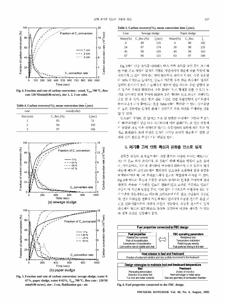
Fig. 4. Fraction and rate of carbon conversion : wood, Tbed 700oC, flowrate 120 Nl/min(0.86 m/sec), size 1, 2, 3 cm cube.
Table 4. Carbon recovery(%), mean conversion time tc(sec)
case wood(cube)
Size (cm) C_Rec.(%) tc(sec)1 83 512 94 1053 97 166
Fig. 5. Fraction and rate of carbon conversion: sewage sludge, water 0-67%, paper sludge, water 0-63%, Tbed 700oC, flow rate : 120 Nl/min(0.86 m/sec), size : 2 cm, fluidization gas : air.
Table 5. Carbon recovery(%), mean conversion time tc(sec).
Case Sewage sludge Paper sludge
Water(%) C_Rec.(%) tc(sec) Water(%) C_Rec. tc
0 89 125 0 89 18224 87 174 30 98 23545 99 193 49 94 16367 96 121 63 97 100
Fig. 6. Fuel properties connected to the FBC design.
HWAHAK KONGHAK Vol. 40, No. 4, August, 2002

528 �����������
un,
op-
��� ��� �� ®7�� ;V� U� ���� D� �� ��
rtG ��� ���� ¸¹/º';¹ Á3 �2p� wx �Y��
£[(� a� ¤z(�.
RDF� ´� l�.� \X $M ��2� '�M ��(� ���
¸¹�� 9��:� �X ��¼ ù ²�� >«7 º';¹� b
�d kl,� �I º';¹��� �� �:^G [y�� !�.
�� U>(V º';¹� Á3 �'� 2q ��� �� EA� ÝM
=)Ä Ì aC� #Âd�. � ��� ¶j l�.� \� PQ� ¸
¹ Á3� �2(� a )N2 ø2u à@ �� ��� 3Ô(� �
I�� º';¹ 9��:, 2q e� ð², e�>, e� "�Á3� ´
wx T� wB� ùÏ� ð�[ z�d�.
,G �. -�� 012�� l�.� Rj µ� PQ� ¸¹ Á
3� �2(� �I�� ;� ��� ´ á� �¬� ¤z(�. ��
�[ w¡=) 012[ ���� ±²=� b� ��=� ¶j, ��
^� op �� rt� Ôp2� aG wx �� wB� ��IÄu �
�. , -.� / ¶j� �� �� Ë3[ 9)22u �� 7B
�� $M ��2� PQ� b9 ���: B�* ��d 012;
� �Ò¼�. 012 ²�� , -.� \G â ²�� ¸¹ 9��
:� �Ò2X ̧ ¹ Á3[ 9)¼�. � P kl,� ¸¹ ��^ �
O� �(=) kl, �� �Ã� º';¹ ��� ��Ì [Lt�
!�. ¸¹ Á3� �2(� �I�� ¸¹�� � EÐ.G 7[��
!� �7 ́ � õ t,� / ��[ ;� ��� @�(�. RDF
m mH� ´� kl, -.� / ��� ;� ��� ·_Ì ¶j
��J e�� "�Á3 wB� ð�[ z�=� ;� �� ·_.�
ûU� wB=2 øG ¶j º';¹ �� �:^G 2m¡M \O �
�� !�
6. � �
��_ ��� ��� }�� X9 ²� �� © �,I ��G ¨
(ã�. � ®7��� X9 ���� ��� o� �,I © �� r
tG £[Ì !§�.
��� ,� rt ��� �� rt� Rj � �¢G ð§�. ×
kl 7B�� ?3[ @I2� RDF� ¶j ��� ¸¹�� ²�[
$M ,�=) ×kl7B7 õ �� 7B� ��� O)m� b9@
C� ��� '�M ¼¨=� a� �T=§�. ²�� ,�[ @M O
)m� ²�� þÇ[ �2=� mH, ��d ( 012� û2 01
2� ¶j� Âx@C� ��� ¼¨=§�.
H«� ¸¹ ÷¶G �t-C�� ,� rt� ?� ��� P-�
Ý� ��� UI ×kl 7B7 õ �� 7BG �,Ì !§�. ×
kl 7B ��� ��� op LM 2J[ Æ2u õ ��� ���
,� rt� op LM �¢G Q5�.
012� ¶j , -.� op �� rt� 2(� aG �TÌ
!§�. , -.� \Ò2$ ��� , ��7B� �I ×kl 7
B� 0*22u � ó ��[ ,�=$� ×kl 7B7 õ �� ��
ÝÈ[ [Ë=� aG �TÌ !�.
��� ���� ¸¹/º';¹ Á3 �2p� wx �Y�� ��®
7� ;V� U� ���� D� �� �� rtG £[(ã�.
���
+,-. /�
C* : concentration of CO, CO2, CxHy(CH base) [mol/Nm3]
f : fraction of carbon conversion [%]
fC : carbon mass fraction from element analysis
F_rate : flow rate [l/min]
HHV : higher heating value [cal/g]
MFC : mass flow controller
mfuel : mass of fuel input [g]
n : mole number [mol]
N : total mole number [mol]
C_Rec : carbon recovery [%]
Q : combustion gas flow rate [Nm3/sec]
t : time [sec]
: overall burnout time [sec]
tc : mean carbon conversion time [sec]
!�"#
1� Hodgkinson, N. and Thurlow, G. G.: AIChE symposium series, 73,
109(1977).
2. Lee, J. K., Lee, K. H., Jang, J. G., Lee, N. S., Lim, J. S. and Ch
H. S.: HWAHAK KONGHAK, 30, 228(1992).
3. Jacobs, J. P.: Chem. Eng. Science, 54, 5559(1999).
4. Bautista-Margulis, R.G., Siddall, R.G. and Manzanares-Papayan
oulos, L.Y.: Fuel, 75, 1737(1996).
5. Winter, F., Prah, M. E. and Hofbauer, H.: Combustion and Flame,
108, 302(1997).
6. Kim, J.-S., Kim, S.-J., Yun, J.-S., Kang, Y. and Choi, M.-J.: HWA-
HAK KONGHAK, 39, 465(2001).
7. Lau, I. T. and Friedrich, F. D.: AIChE symposium series, 84, 89(1980).
8. Choi, J., Park, Y. and Choi, S.: HWAHAK KONGHAK, 39, 629(2001).
9. Choi, J., Park, Y. and Choi, S.: J. Korean Solid Wastes Eng. Society,
18, 1(2001).
10. Arena, U., Cammarota, A. and Mastellone, M. L.: Fuel, 77, 1185(1998).
tB
���� �40� �4� 2002� 8�