combinational circuits - rpedroni
TRANSCRIPT
DigitalElectronicsandDesignwithFPGAsandVHDL,VolneiA.Pedroni 1
Review of
Combinational Circuits
DigitalElectronicsandDesignwithFPGAsandVHDL,VolneiA.Pedroni 2
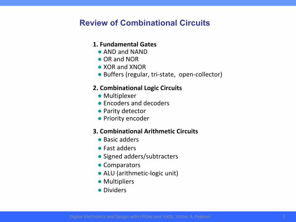
Review of Combinational Circuits
1.FundamentalGates●ANDandNAND●ORandNOR●XORandXNOR●Buffers(regular,tri-state,open-collector)2.CombinationalLogicCircuits●Multiplexer●Encodersanddecoders●Paritydetector●Priorityencoder3.CombinationalArithmeticCircuits●Basicadders●Fastadders●Signedadders/subtracters●Comparators●ALU(arithmetic-logicunit)●Multipliers●Dividers
DigitalElectronicsandDesignwithFPGAsandVHDL,VolneiA.Pedroni 3
input
output
Combinational logic
clock
reset
input
output
Combinational logic
Storage
elements
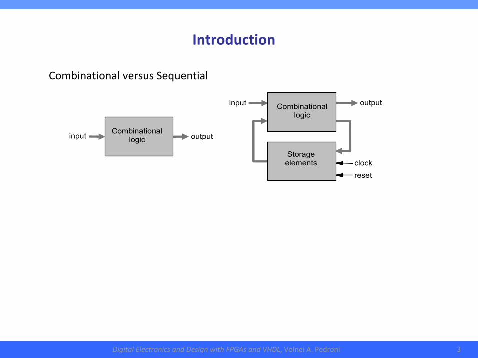
CombinationalversusSequential
Introduction
DigitalElectronicsandDesignwithFPGAsandVHDL,VolneiA.Pedroni 4
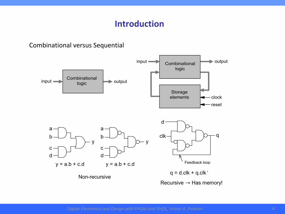
Introduction
clk
d q
Feedback loop
q = d.clk + q.clk ʹ
a
b c
d
y y = a.b + c.d
a
b c
d
y y = a.b + c.d
Non-recursive
Recursive → Has memory!
CombinationalversusSequential
input
output
Combinational logic
clock
reset
input
output
Combinational logic
Storage
elements
DigitalElectronicsandDesignwithFPGAsandVHDL,VolneiA.Pedroni 5
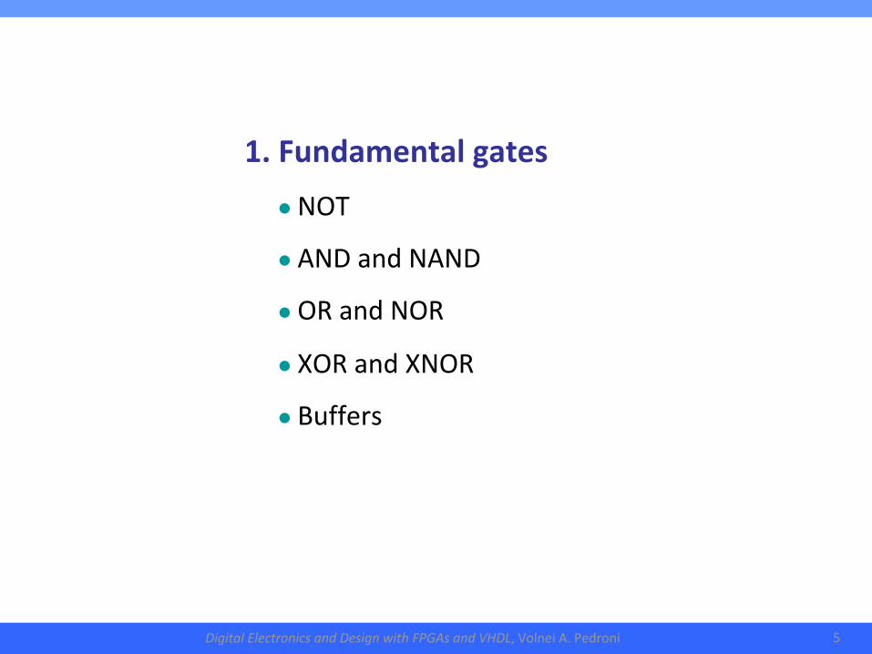
1.Fundamentalgates●NOT
●ANDandNAND
●ORandNOR
●XORandXNOR
●Buffers
DigitalElectronicsandDesignwithFPGAsandVHDL,VolneiA.Pedroni 6
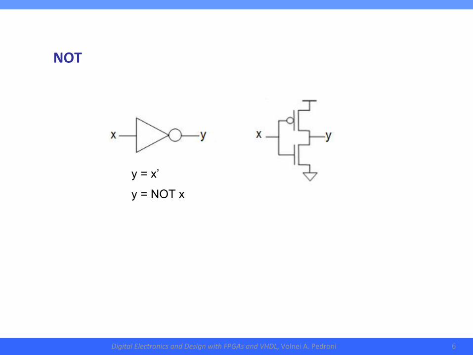
NOT
y = x’
y = NOT x
DigitalElectronicsandDesignwithFPGAsandVHDL,VolneiA.Pedroni 7
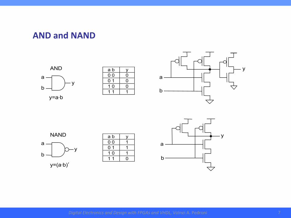
ANDandNAND
a b
a b
y
y a b y 0 0 0 0 1 0 1 0 0 1 1 1
a b
y
AND
a b y 0 0 1 0 1 1 1 0 1 1 1 0
NAND
a b
y
y=a⋅b
y=(a⋅b)ʹ
DigitalElectronicsandDesignwithFPGAsandVHDL,VolneiA.Pedroni 8
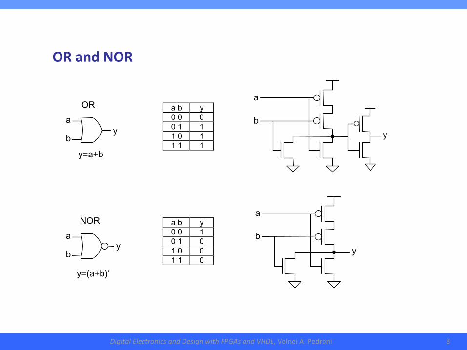
ORandNOR
a b
a b
OR
NOR
a b y 0 0 0 0 1 1 1 0 1 1 1 1
a b
y
a b y 0 0 1 0 1 0 1 0 0 1 1 0
a b
y
y
y
y=a+b
y=(a+b)ʹ
DigitalElectronicsandDesignwithFPGAsandVHDL,VolneiA.Pedroni 9
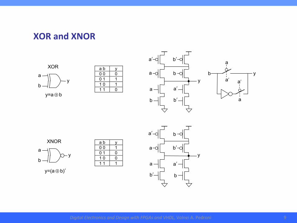
XORandXNOR
aʹ
a
a
aʹ
b
y
a b y 0 0 0 0 1 1 1 0 1 1 1 0
a b y 0 0 1 0 1 0 1 0 0 1 1 1
bʹ
aʹ
a
aʹ
b
a
b
bʹ
y
b
aʹ
a
aʹ
bʹ
a
bʹ
b
y
XOR
a b
y
y=a ⊕ b
XNOR
a b
y
y=(a ⊕ b)ʹ
DigitalElectronicsandDesignwithFPGAsandVHDL,VolneiA.Pedroni 10
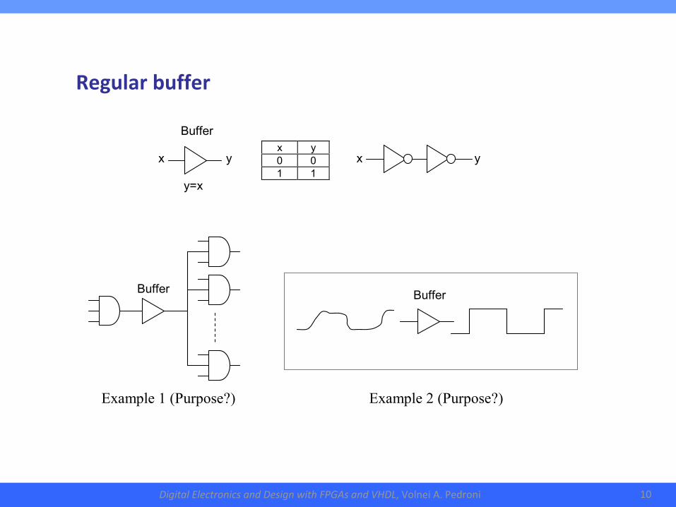
Regularbuffer
Buffer
Buffer
Example 1 (Purpose?)
x y 0 0 1 1
x
y
x
y
Buffer y=x
Example 2 (Purpose?)
DigitalElectronicsandDesignwithFPGAsandVHDL,VolneiA.Pedroni 11
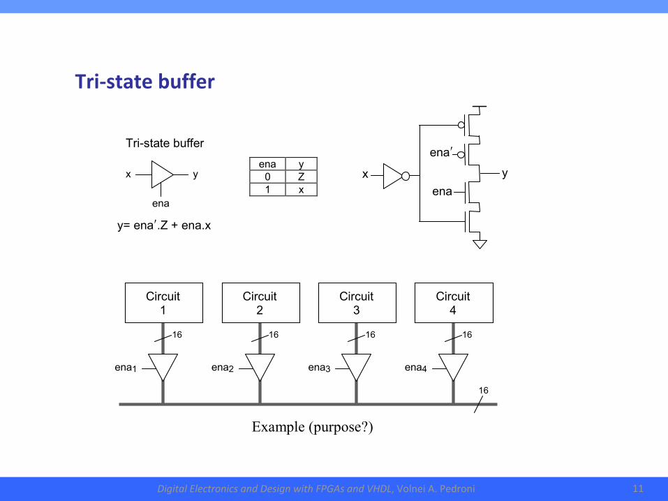
Tri-statebuffer
Tri-state buffer
ena y 0 Z 1 x
ena
x
y
enaʹ
ena
x
y
y= enaʹ.Z + ena.x
ena2 ena3 ena4 ena1
Circuit 1
Circuit 2
Circuit 3
Circuit 4
16
16
16
16
16
Example (purpose?)
DigitalElectronicsandDesignwithFPGAsandVHDL,VolneiA.Pedroni 12
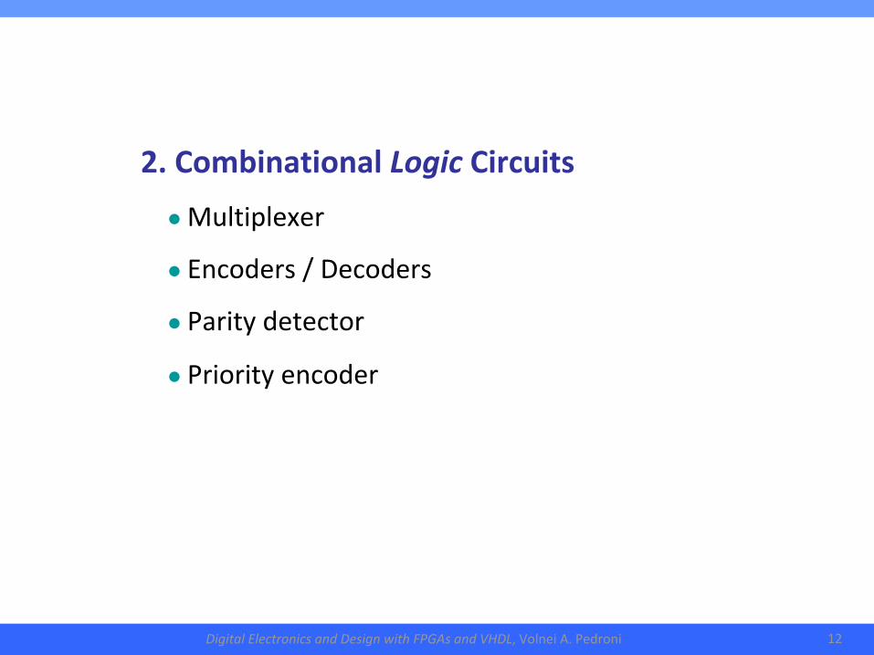
2.CombinationalLogicCircuits●Multiplexer
●Encoders/Decoders
●Paritydetector
●Priorityencoder
DigitalElectronicsandDesignwithFPGAsandVHDL,VolneiA.Pedroni 13
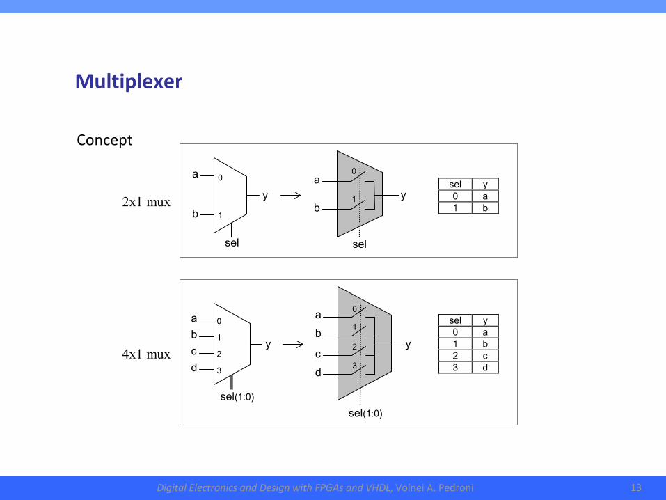
Multiplexer
sel y 0 a 1 b
a
sel
y
b
0
1
sel
a b
0
1
y
sel(1:0)
a b
0
1
y
2
3
c d sel(1:0)
y
a b c d
0
1
2
3
sel y 0 a 1 b 2 c 3 d
2x1 mux
4x1 mux
Concept
DigitalElectronicsandDesignwithFPGAsandVHDL,VolneiA.Pedroni 14
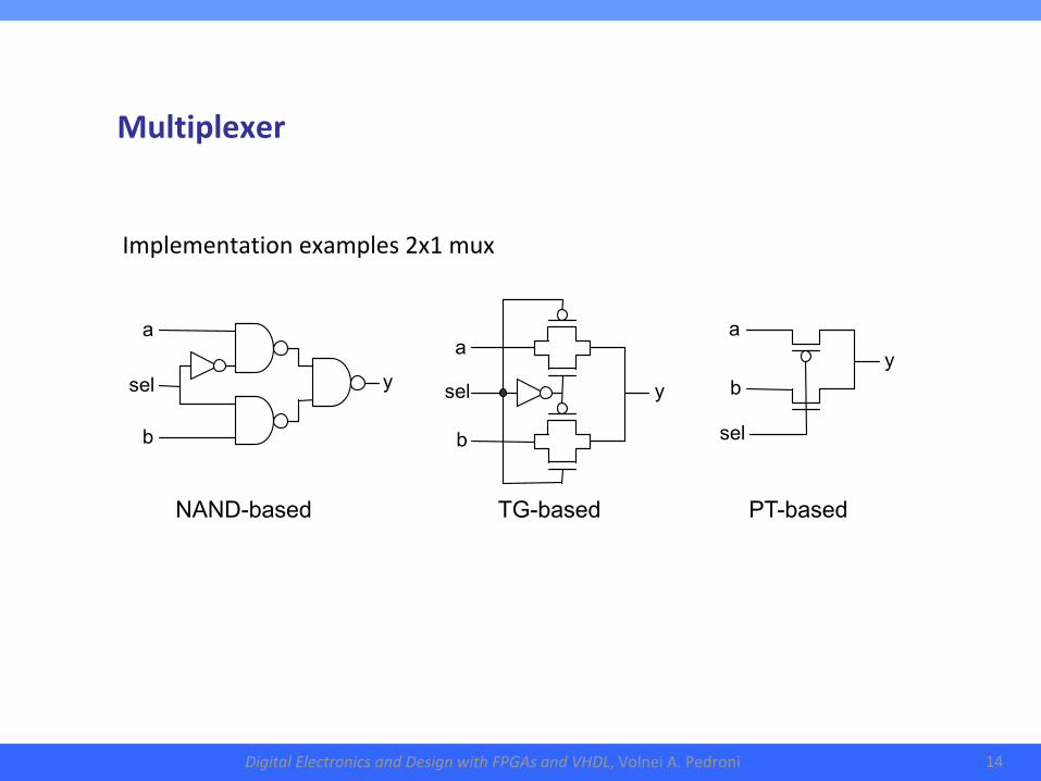
Implementationexamples2x1mux
a b
sel
y
sel
a
b
y sel
a b
y
NAND-based TG-based PT-based
Multiplexer
DigitalElectronicsandDesignwithFPGAsandVHDL,VolneiA.Pedroni 15
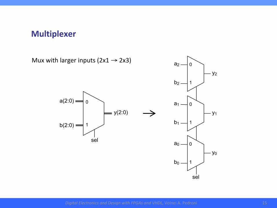
Muxwithlargerinputs(2x1→2x3)
sel
a2 b2
y2
0 1
a1 b1
y1
0 1
a0 b0
y0
0 1
y(2:0)
sel
a(2:0) b(2:0)
0 1
Multiplexer
DigitalElectronicsandDesignwithFPGAsandVHDL,VolneiA.Pedroni 16
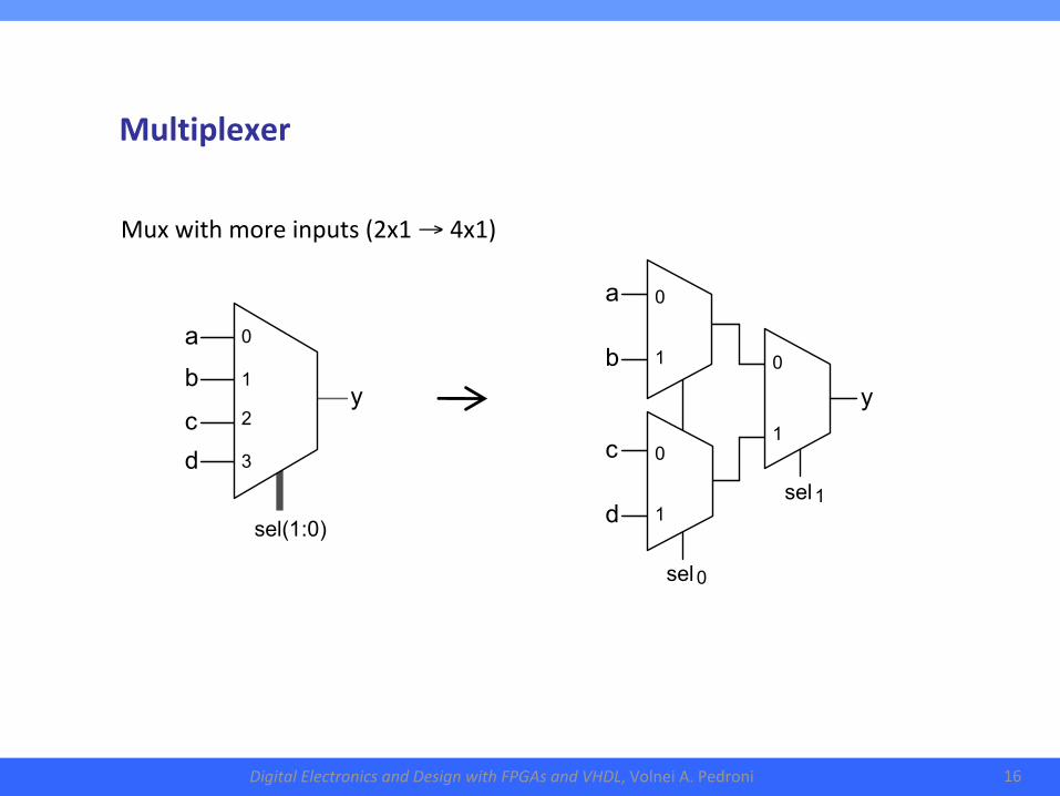
Muxwithmoreinputs(2x1→4x1)
sel 0
sel 1
a b c d
0 1
0 1
y
0 1
sel(1:0)
y
a b c d
0 1 2 3
Multiplexer
DigitalElectronicsandDesignwithFPGAsandVHDL,VolneiA.Pedroni 17
2.CombinationalLogicCircuits●Multiplexer
●Encoders/Decoders
●Paritydetector
●Priorityencoder
DigitalElectronicsandDesignwithFPGAsandVHDL,VolneiA.Pedroni 18
Encoders/Decoders
x0
x1
…
xN−1
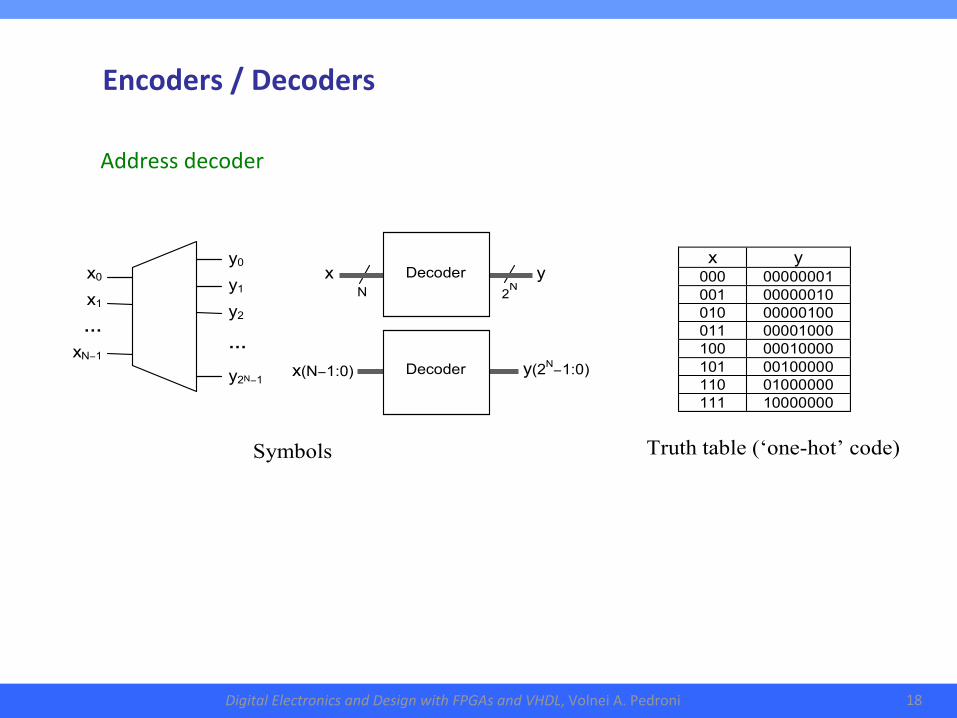
x y 000 00000001 001 00000010 010 00000100 011 00001000 100 00010000 101 00100000 110 01000000 111 10000000
y0
y1
y2
…
y2N−1
x
y
N
2N
Decoder
x(N−1:0)
y(2N−1:0)
Decoder
Symbols Truth table (‘one-hot’ code)
Addressdecoder
DigitalElectronicsandDesignwithFPGAsandVHDL,VolneiA.Pedroni 19
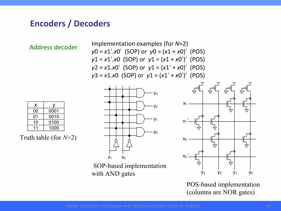
Implementationexamples(forN=2)y0=x1ʹ.x0ʹ(SOP)ory0=(x1+x0)ʹ(POS)y1=x1ʹ.x0(SOP)ory1=(x1+x0ʹ)ʹ(POS)y2=x1.x0ʹ(SOP)ory1=(x1ʹ+x0)ʹ(POS)y3=x1.x0(SOP)ory1=(x1ʹ+x0ʹ)ʹ(POS)
SOP-based implementation with AND gates
Truth table (for N=2)
x y 00 0001 01 0010 10 0100 11 1000
x1 x1 ʹ
x0 x0 ʹ
y3 y2 y1 y0
POS-based implementation (columns are NOR gates)
y3 y2
y1 y0
x1 x0
Encoders/Decoders
Addressdecoder
DigitalElectronicsandDesignwithFPGAsandVHDL,VolneiA.Pedroni 20
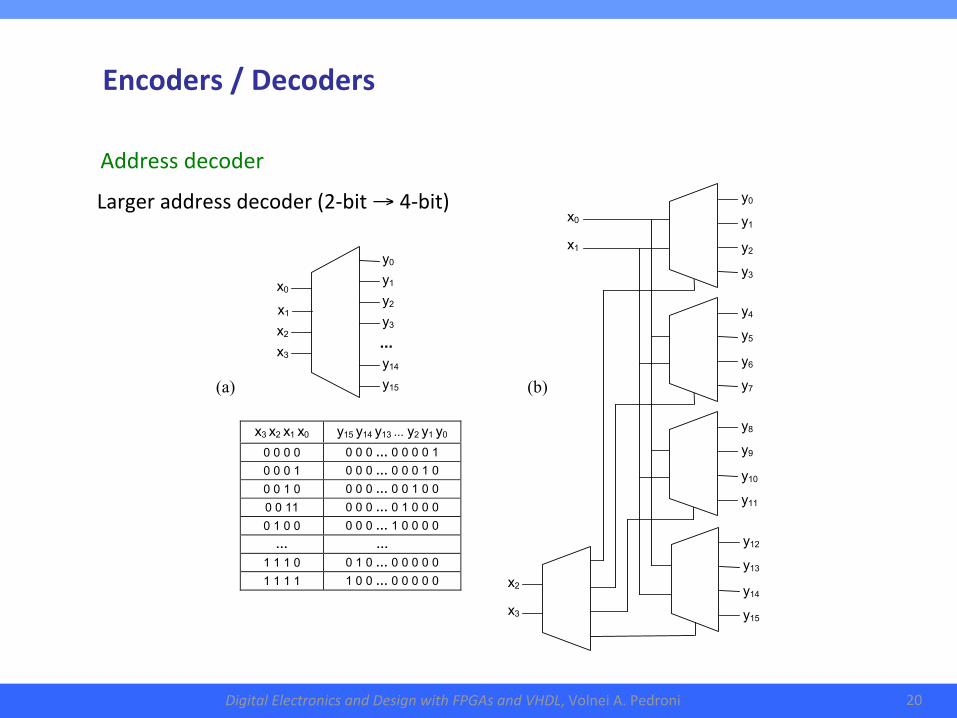
Largeraddressdecoder(2-bit→4-bit)
(a)
x3 x2 x1 x0 y15 y14 y13 ... y2 y1 y0 0 0 0 0 0 0 0 … 0 0 0 0 1 0 0 0 1 0 0 0 … 0 0 0 1 0 0 0 1 0 0 0 0 … 0 0 1 0 0 0 0 11 0 0 0 … 0 1 0 0 0 0 1 0 0 0 0 0 … 1 0 0 0 0 … …
1 1 1 0 0 1 0 … 0 0 0 0 0 1 1 1 1 1 0 0 … 0 0 0 0 0
x0
y0
y1
y2
y3
y14
y15
x1
x2
x3 ...
y0
y1
y2
y3
y4
y5
y6
y7
y8
y9
y10
y11
y12
y13
y14
y15
x2 x3
x0 x1
(b)
Encoders/Decoders
Addressdecoder
DigitalElectronicsandDesignwithFPGAsandVHDL,VolneiA.Pedroni 21
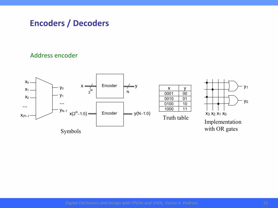
Addressencoder
x y
0001 00 0010 01 0100 10 1000 11
y1 y0 x3 x2 x1 x0
x(2N−1:0)
y(N−1:0)
x
y
N
2N
Encoder
Encoder
y0
y1
…
yN−1
x0
x1
x2
…
x2N−1
Symbols
Truth table Implementation with OR gates
Encoders/Decoders
DigitalElectronicsandDesignwithFPGAsandVHDL,VolneiA.Pedroni 22
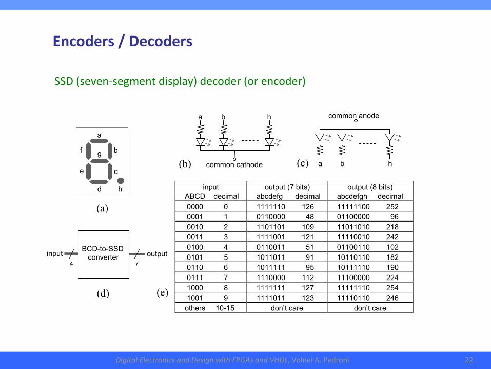
SSD(seven-segmentdisplay)decoder(orencoder)
input
output
BCD-to-SSD converter
7
4
input ABCD decimal
output (7 bits) abcdefg decimal
output (8 bits) abcdefgh decimal
0000 0 1111110 126 11111100 252 0001 1 0110000 48 01100000 96 0010 2 1101101 109 11011010 218 0011 3 1111001 121 11110010 242 0100 4 0110011 51 01100110 102 0101 5 1011011 91 10110110 182 0110 6 1011111 95 10111110 190 0111 7 1110000 112 11100000 224 1000 8 1111111 127 11111110 254 1001 9 1111011 123 11110110 246 others 10-15 don’t care don’t care
(a)
a
b
c
d
e
f g
h
(c) (b)
(d) (e)
common cathode
common anode
a
b
h
a
b
h
Encoders/Decoders
DigitalElectronicsandDesignwithFPGAsandVHDL,VolneiA.Pedroni 23
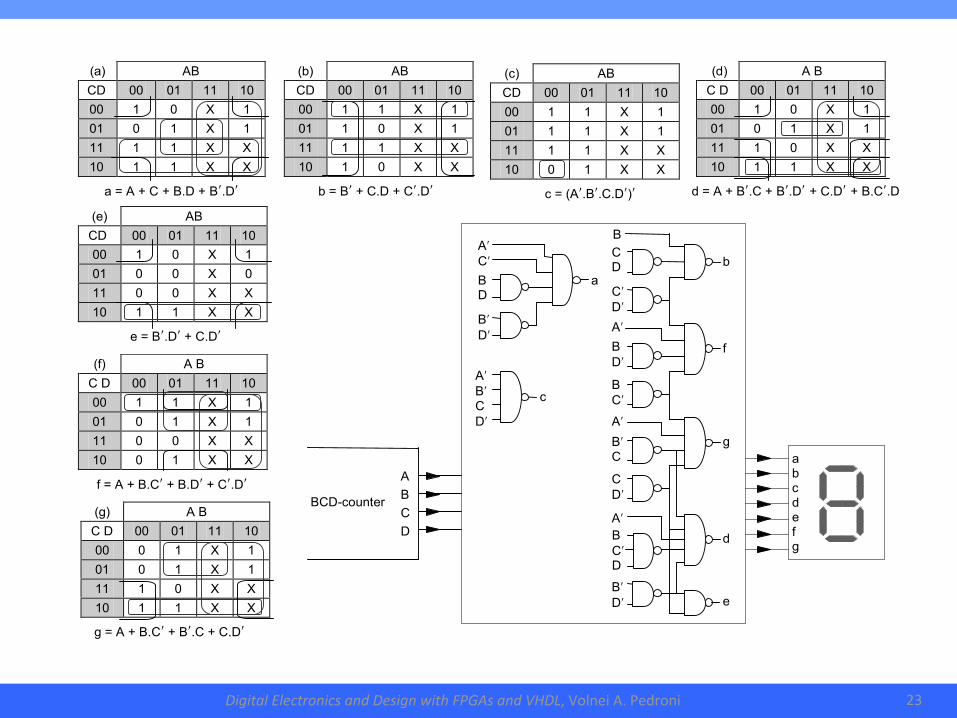
a = A + C + B.D + Bʹ.Dʹ
(a) AB
CD 00 01 11 10 00 1 0 X 1 01 0 1 X 1 11 1 1 X X 10 1 1 X X
c = (Aʹ.Bʹ.C.Dʹ)ʹ
(c) AB
CD 00 01 11 10 00 1 1 X 1 01 1 1 X 1 11 1 1 X X 10 0 1 X X
(b) AB
CD 00 01 11 10 00 1 1 X 1 01 1 0 X 1 11 1 1 X X 10 1 0 X X
b = Bʹ + C.D + Cʹ.Dʹ Bʹ.Dʹ
d = A + Bʹ.C + Bʹ.Dʹ + C.Dʹ + B.Cʹ.D
(d) A B
C D 00 01 11 10 00 1 0 X 1 01 0 1 X 1 11 1 0 X X 10 1 1 X X
e = Bʹ.Dʹ + C.Dʹ
(e) AB
CD 00 01 11 10 00 1 0 X 1 01 0 0 X 0 11 0 0 X X 10 1 1 X X
f = A + B.Cʹ + B.Dʹ + Cʹ.Dʹ
(f) A B
C D 00 01 11 10 00 1 1 X 1 01 0 1 X 1 11 0 0 X X 10 0 1 X X
g = A + B.Cʹ + Bʹ.C + C.Dʹ
(g) A B
C D 00 01 11 10 00 0 1 X 1 01 0 1 X 1 11 1 0 X X 10 1 1 X X
B Cʹ D
Bʹ Dʹ
Cʹ Dʹ
C D
Aʹ
B Cʹ
B Dʹ Aʹ
C Dʹ
Bʹ C
Aʹ
B
d
b
f g
e
A B C D
BCD-counter
a b c d e f g
Aʹ Bʹ C Dʹ
Aʹ Cʹ
B D
Bʹ Dʹ c
a
DigitalElectronicsandDesignwithFPGAsandVHDL,VolneiA.Pedroni 24
2.CombinationalLogicCircuits●Multiplexer
●Encoders/Decoders
●Paritydetector
●Priorityencoder
DigitalElectronicsandDesignwithFPGAsandVHDL,VolneiA.Pedroni 25
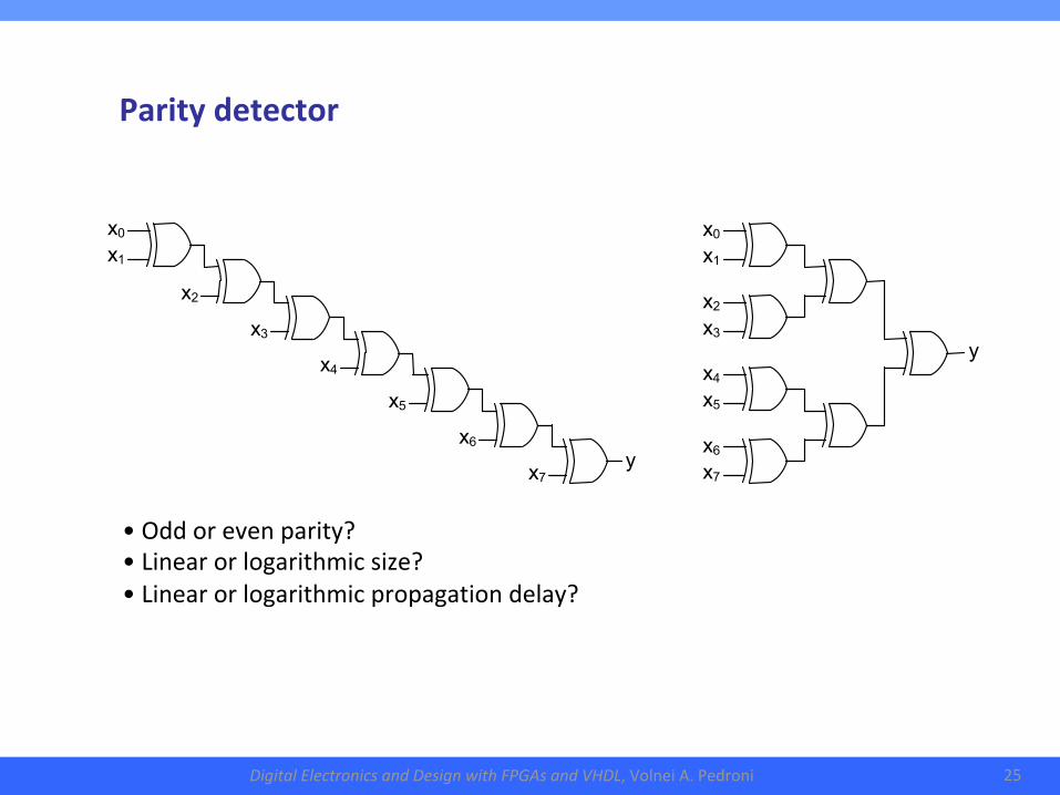
Paritydetector
y
x0
x1
x2
x3
x4
x5
x6
x7
y
x0
x1
x2
x3
x4
x5
x6
x7
• Oddorevenparity?• Linearorlogarithmicsize?• Linearorlogarithmicpropagationdelay?
DigitalElectronicsandDesignwithFPGAsandVHDL,VolneiA.Pedroni 26
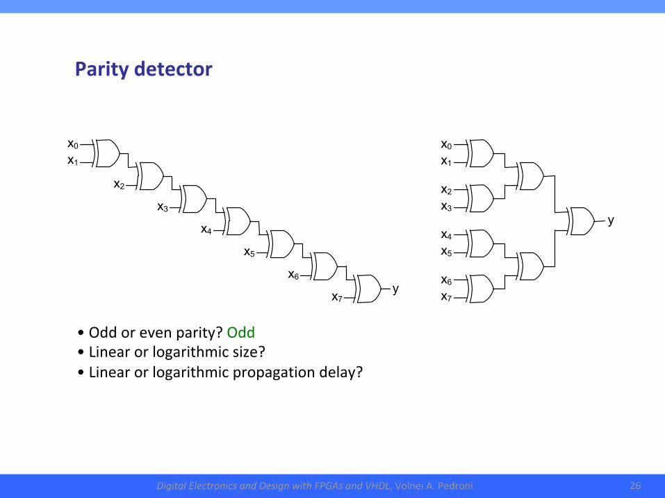
Paritydetector
y
x0
x1
x2
x3
x4
x5
x6
x7
y
x0
x1
x2
x3
x4
x5
x6
x7
• Oddorevenparity?Odd• Linearorlogarithmicsize?• Linearorlogarithmicpropagationdelay?
DigitalElectronicsandDesignwithFPGAsandVHDL,VolneiA.Pedroni 27
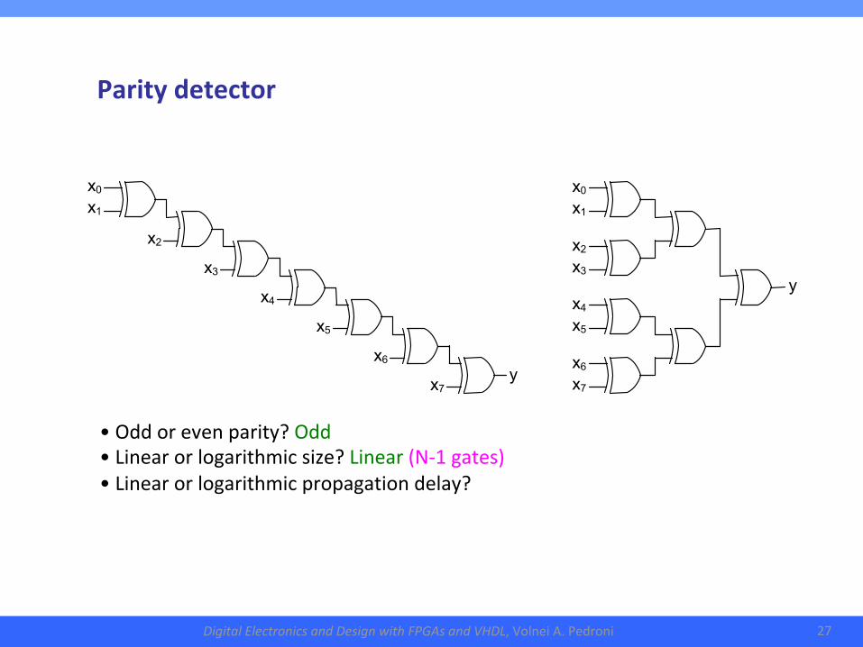
Paritydetector
y
x0
x1
x2
x3
x4
x5
x6
x7
y
x0
x1
x2
x3
x4
x5
x6
x7
• Oddorevenparity?Odd• Linearorlogarithmicsize?Linear(N-1gates)• Linearorlogarithmicpropagationdelay?
DigitalElectronicsandDesignwithFPGAsandVHDL,VolneiA.Pedroni 28
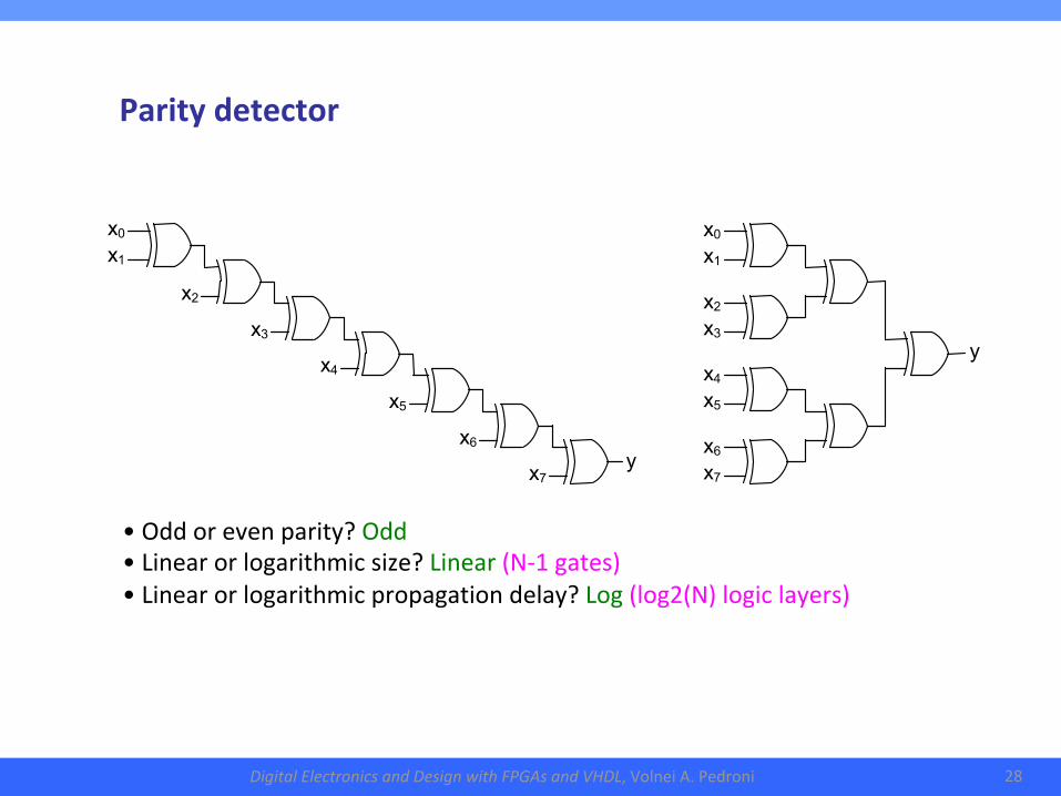
Paritydetector
y
x0
x1
x2
x3
x4
x5
x6
x7
y
x0
x1
x2
x3
x4
x5
x6
x7
• Oddorevenparity?Odd• Linearorlogarithmicsize?Linear(N-1gates)• Linearorlogarithmicpropagationdelay?Log(log2(N)logiclayers)
DigitalElectronicsandDesignwithFPGAsandVHDL,VolneiA.Pedroni 29
2.CombinationalLogicCircuits●Multiplexer
●Encoders/Decoders
●Paritydetector
●Priorityencoder
DigitalElectronicsandDesignwithFPGAsandVHDL,VolneiA.Pedroni 30
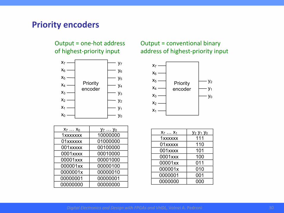
Priorityencoders
y2
y1
y0
x7
x6
x5
x4
x3
x2
x1
Priority encoder
x7 … x0 y7 … y0
1xxxxxxx 10000000 01xxxxxx 01000000 001xxxxx 00100000 0001xxxx 00010000 00001xxx 00001000 000001xx 00000100 0000001x 00000010 00000001 00000001 00000000 00000000
x7 … x1 y2 y1 y0 1xxxxxx 111 01xxxxx 110 001xxxx 101 0001xxx 100 00001xx 011 000001x 010 0000001 001 0000000 000
x7
x6
x5
x4
x3
x2
x1
x0
y7
y6
y5
y4
y3
y2
y1
y0
Priority encoder
Output=one-hotaddressofhighest-priorityinput
Output=conventionalbinaryaddressofhighest-priorityinput
DigitalElectronicsandDesignwithFPGAsandVHDL,VolneiA.Pedroni 31
3.CombinationalArithmeticCircuits●Basicadders
●Fastadders
●Signedadders/subtracters
●Comparators
●ALU(arithmetic-logicunit)
●Multipliers
●Dividers
DigitalElectronicsandDesignwithFPGAsandVHDL,VolneiA.Pedroni 32
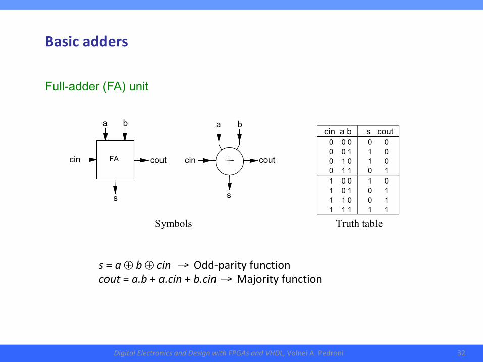
Basicadders
a b a b cin a b s cout
0 0 0 0 0 1 0 1 0 0 1 1
0 0 1 0 1 0 0 1
1 0 0 1 0 1 1 1 0 1 1 1
1 0 0 1 0 1 1 1
Symbols Truth table
s
cin
cout
FA cin
cout
s
s=a⊕b⊕cin→Odd-parityfunctioncout=a.b+a.cin+b.cin→Majorityfunction
Full-adder (FA) unit
DigitalElectronicsandDesignwithFPGAsandVHDL,VolneiA.Pedroni 33
3.CombinationalArithmeticCircuits●Basicadders
●Fastadders
●Signedadders/subtracters
●Comparators
●ALU(arithmetic-logicunit)
●Multipliers
●Dividers
DigitalElectronicsandDesignwithFPGAsandVHDL,VolneiA.Pedroni 34
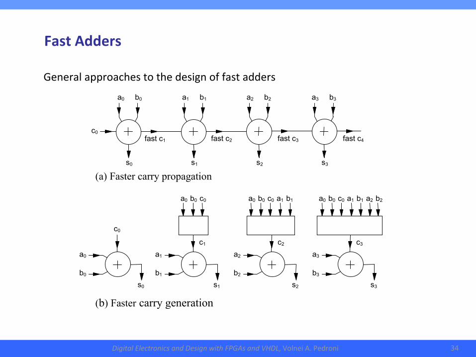
Generalapproachestothedesignoffastadders
(a) Faster carry propagation
a0 b0 c0 a1 b1 a2 b2
c3
a0 b0 c0 a1 b1
c2
a0 b0 c0
c1
c0
s1
a1 b1
s2
a2 b2
s3
a3 b3
s0
a0 b0
c0
a0 b0 a1 b1 a2 b2 a3 b3 s
s0
s1
s2
s3
fast c1 fast c2 fast c3 fast c4
(b) Faster carry generation
FastAdders
DigitalElectronicsandDesignwithFPGAsandVHDL,VolneiA.Pedroni 35
3.CombinationalArithmeticCircuits●Basicadders
●Fastadders
●Signedadders/subtracters
●Comparators
●ALU(arithmetic-logicunit)
●Multipliers
●Dividers
DigitalElectronicsandDesignwithFPGAsandVHDL,VolneiA.Pedroni 36
s0
s3
s1
s2
b3* s0
s1
s2
s3
op_a op_b
c4 (cout) overflow
c0 (cin)
Two’s com plement er
Adder
b0 a0
0 1
0 1
b1 a1
0 1
0 1
b2 a2
0 1
0 1
b3 a3
0 1
0 1
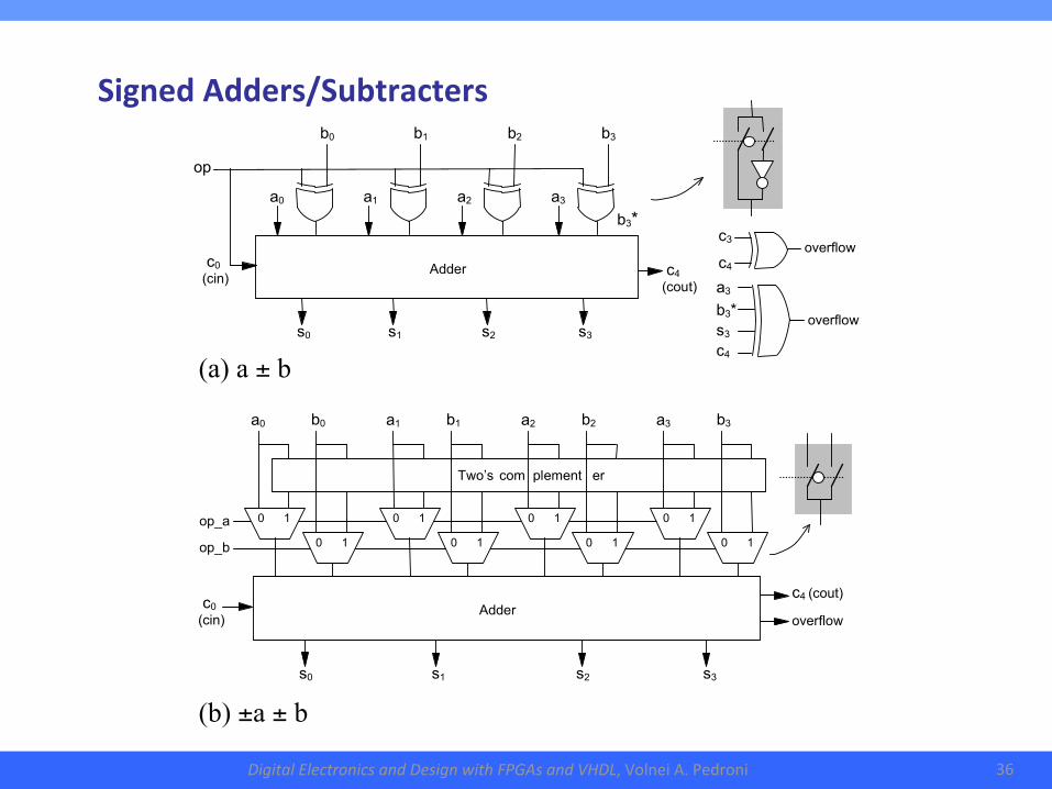
(a) a ± b
op
c0 (cin)
a0 a1 a2 a3
b0 b1 b2 b3
c4 (cout)
Adder
c3
c4
overflow
a3
b3*
s3
c4
overflow
(b) ±a ± b
SignedAdders/Subtracters
DigitalElectronicsandDesignwithFPGAsandVHDL,VolneiA.Pedroni 37
3.CombinationalArithmeticCircuits●Basicadders
●Fastadders
●Signedadders/subtracters
●Comparators
●ALU(arithmetic-logicunit)
●Multipliers
●Dividers
DigitalElectronicsandDesignwithFPGAsandVHDL,VolneiA.Pedroni 38
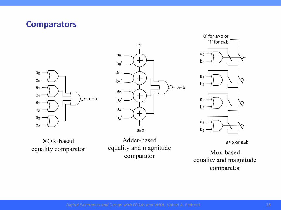
a0
b0ʹ
a1
b1ʹ
a2
b2ʹ
a3
b3ʹ
‘1’
a≥b
a=b
XOR-based equality comparator
a=b
a0
b0 a1
b1 a2
b2 a3
b3
a>b or a≥b
a0
b0
a1
b2
a2
b2
a3
b3
‘0’ for a>b or ‘1’ for a≥b
Adder-based equality and magnitude
comparator Mux-based equality and magnitude
comparator
Comparators
DigitalElectronicsandDesignwithFPGAsandVHDL,VolneiA.Pedroni 39
3.CombinationalArithmeticCircuits●Basicadders
●Fastadders
●Signedadders/subtracters
●Comparators
●ALU(arithmetic-logicunit)
●Multipliers
●Dividers
DigitalElectronicsandDesignwithFPGAsandVHDL,VolneiA.Pedroni 40
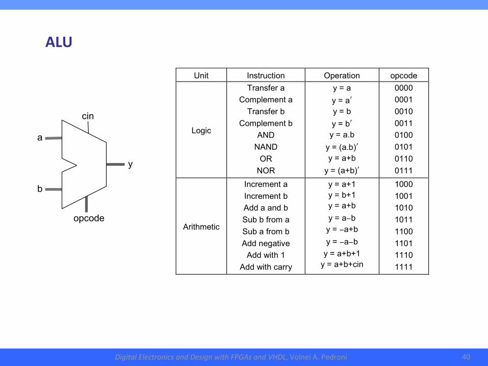
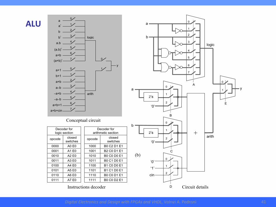
Unit Instruction Operation opcode
Logic
Transfer a Complement a
Transfer b Complement b
AND NAND
OR NOR
y = a y = aʹ y = b y = bʹ y = a.b
y = (a.b)ʹ y = a+b
y = (a+b)ʹ
0000 0001 0010 0011 0100 0101 0110 0111
Arithmetic
Increment a Increment b Add a and b Sub b from a Sub a from b Add negative
Add with 1 Add with carry
y = a+1 y = b+1 y = a+b y = a−b
y = −a+b y = −a−b
y = a+b+1 y = a+b+cin
1000 1001 1010 1011 1100 1101 1110 1111
cin
a
b
y
opcode
ALU
DigitalElectronicsandDesignwithFPGAsandVHDL,VolneiA.Pedroni 41
a b
aʹ
a.b
bʹ
a+b
(a.b)ʹ (a+b)ʹ a+1
b+1 a+b a−b −a+b
−a−b a+b+1
a+b+cin
0 1 2 3 4 5 6 7 0 1 2 3 4 5 6 7
arith
logic
0 1
y
Decoder for logic section
opcode closed switches
0000 A0 E0 0001 A1 E0 0010 A2 E0 0011 A3 E0 0100 A4 E0 0101 A5 E0 0110 A6 E0 0111 A7 E0
Decoder for arithmetic section
opcode closed switches
1000 B0 C2 D1 E1 1001 B2 C0 D1 E1 1010 B0 C0 D0 E1 1011 B0 C1 D0 E1 1100 B1 C0 D0 E1 1101 B1 C1 D0 E1 1110 B0 C0 D1 E1 1111 B0 C0 D2 E1
Conceptual circuit
Instructions decoder
(b)
logic
arith
A
b
a
1
0
4 5
7
6
3
2
‘0’ cin
‘1’
0
2
1
‘0’
a
0
2
1
2’s
‘0’
b
0
2
1
2’s
+
B
C
D
0 1
E
y
Circuit details
ALU

DigitalElectronicsandDesignwithFPGAsandVHDL,VolneiA.Pedroni 42
3.CombinationalArithmeticCircuits●Basicadders
●Fastadders
●Signedadders/subtracters
●Comparators
●ALU(arithmetic-logicunit)
●Multipliers
●Dividers
DigitalElectronicsandDesignwithFPGAsandVHDL,VolneiA.Pedroni 43
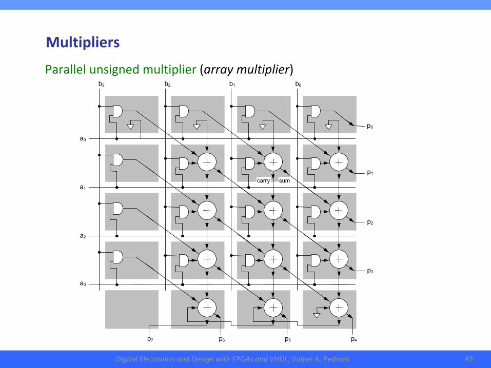
Parallelunsignedmultiplier(arraymultiplier)
p7
p6
p5
p4
p2
p3
p1
p0
a2
a3
a1
a0
b3
b2
b1
b0
carry
sum
Multipliers
DigitalElectronicsandDesignwithFPGAsandVHDL,VolneiA.Pedroni 44
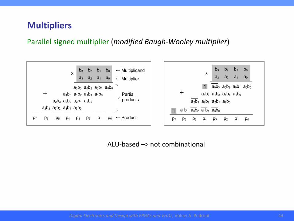
a3 a2 a1 a0
x
b3 b2 b1 b0
a0b3 a0b2 a0b1 a0b0
a1b3 a1b2 a1b1 a1b0
a2b3 a2b2 a2b1 a2b0
a3b3 a3b2 a3b1 a3b0
+
p7 p6 p5 p4 p3 p2 p1 p0
1
1
a3 a2 a1 a0 x
b3 b2 b1 b0
a0b3 a0b2 a0b1 a0b0
a1b3 a1b2 a1b1 a1b0
a2b3 a2b2 a2b1 a2b0
a3b3 a3b2 a3b1 a3b0
+
p7 p6 p5 p4 p3 p2 p1 p0
← Multiplicand
← Multiplier
Partial products
← Product
Parallelsignedmultiplier(modifiedBaugh-Wooleymultiplier)
Multipliers
ALU-based–>notcombinational
DigitalElectronicsandDesignwithFPGAsandVHDL,VolneiA.Pedroni 45
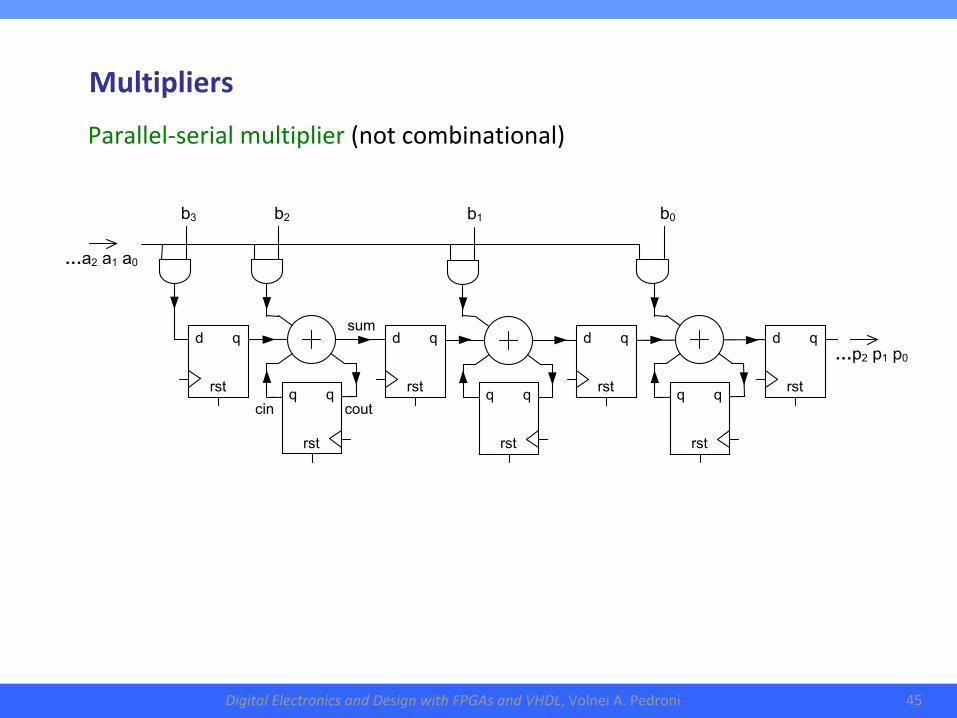
…a2 a1 a0
cout
cin
…p2 p1 p0
sum
b3
b2
d q
rst
b1
b0
q q
rst
d q
rst q q
rst
d q
rst q q
rst
d q
rst
Parallel-serialmultiplier(notcombinational)
Multipliers
DigitalElectronicsandDesignwithFPGAsandVHDL,VolneiA.Pedroni 46
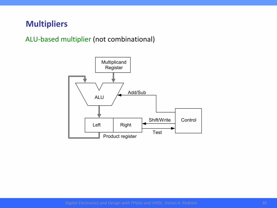
Test
Add/Sub
Product register
Shift/Write
Multiplicand Register
ALU
Control
Right
Left
ALU-basedmultiplier(notcombinational)
Multipliers
DigitalElectronicsandDesignwithFPGAsandVHDL,VolneiA.Pedroni 47
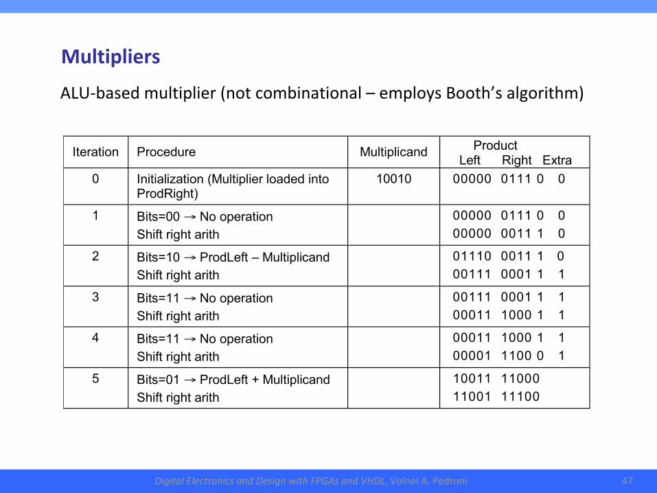
Iteration Procedure Multiplicand Product Left Right Extra
0 Initialization (Multiplier loaded into ProdRight)
10010 00000 0111 0 0
1 Bits=00 → No operation Shift right arith
00000 0111 0 0 00000 0011 1 01
2 Bits=10 → ProdLeft – Multiplicand Shift right arith
01110 0011 1 0 00111 0001 1 1
3 Bits=11 → No operation Shift right arith
00111 0001 1 1 00011 1000 1 11
4 Bits=11 → No operation Shift right arith
00011 1000 1 1 00001 1100 0 1
5 Bits=01 → ProdLeft + Multiplicand Shift right arith
10011 11000 11001 11100
ALU-basedmultiplier(notcombinational–employsBooth’salgorithm)
Multipliers
DigitalElectronicsandDesignwithFPGAsandVHDL,VolneiA.Pedroni 48
3.CombinationalArithmeticCircuits●Basicadders
●Fastadders
●Signedadders/subtracters
●Comparators
●ALU(arithmetic-logicunit)
●Multipliers
●Dividers
DigitalElectronicsandDesignwithFPGAsandVHDL,VolneiA.Pedroni 49
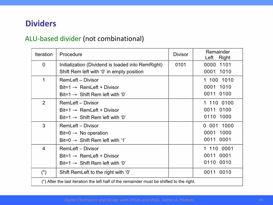
Iteration Procedure Divisor Remainder Left Right
0 Initialization (Dividend is loaded into RemRight) Shift Rem left with ‘0’ in empty position
0101 0000 1101 0001 1010
1 RemLeft – Divisor Bit=1 → RemLeft + Divisor Bit=1 → Shift Rem left with ‘0’
1 100 1010 0001 1010 0011 0100
2 RemLeft – Divisor Bit=1 → RemLeft + Divisor Bit=1 → Shift Rem left with ‘0’
1 110 0100 0011 0100 0110 1000
3 RemLeft – Divisor Bit=0 → No operation Bit=0 → Shift Rem left with ‘1’
0 001 1000 0001 1000 0011 0001
4 RemLeft – Divisor Bit=1 → RemLeft + Divisor Bit=1 → Shift Rem left with ‘0’
1 110 0001 0011 0001 0110 0010
(*) Shift RemLeft to the right with ‘0’ 0011 0010
(*) After the last iteration the left half of the remainder must be shifted to the right.
ALU-baseddivider(notcombinational)
Dividers