columbia county stormwater design amendment
TRANSCRIPT

COLUMBIA COUNTY, GEORGIA SUPPLEMENT TO THE
2018

Columbia County, Georgia Supplement to the GSMM Page 1
{This page left intentionally blank}

Columbia County, Georgia Supplement to the GSMM Page 2
TABLE OF CONTENTS
CHAPTER 1: PURPOSE AND APPLICABILITY ............................................................................. 4
1.1 Applicability ................................................................................................................. 4
1.2 Exemptions .................................................................................................................. 5
CHAPTER 2: STORMWATER MANAGEMENT PLANNING, DESIGN & IMPLEMENTATION ........... 6
2.1 Impacts of Development and Stormwater Runoff ......................................................... 6
2.2 Stormwater Management Standards & Numerical Sizing Criteria .................................. 6
2.2.1 Natural Resources Inventory .......................................................................................... 6
2.2.2 Better Site Design Practices for Stormwater Management ........................................... 6
CHAPTER 3: STORMWATER HYDROLOGY ............................................................................... 8
3.1 Methods for Estimating Stormwater Runoff .................................................................. 8
CHAPTER 4: STORMWATER MANAGEMENT PRACTICES ........................................................ 10
4.1 Stormwater Design Requirements .............................................................................. 10
4.2 Water Quality Performance Criteria ............................................................................ 12
4.3 Criteria for Requiring Stormwater Management ......................................................... 12
4.3.1 Stormwater Management Not Required ..................................................................... 13
4.3.2 Special Provisions for Redevelopment ......................................................................... 14
4.4 Stormwater BMP Specifications .................................................................................. 14
4.5 Miscellaneous Requirements for Stormwater Facilities ............................................... 14
4.5.1 Stormwater Management Facility Access .................................................................... 14
4.5.2 Stormwater Management Facility Fencing .................................................................. 14
4.5.3 Silt Gauge ...................................................................................................................... 15
4.5.4 State Waters Regulated by the Georgia EPD ................................................................ 15
4.5.5 Earthen Berms and Embankments ............................................................................... 15
4.5.6 Dedication of Stormwater Management Facilities ...................................................... 15
CHAPTER 5: STORMWATER DRAINAGE SYSTEM DESIGN ....................................................... 15
5.1 Stormwater Drainage Design Overview 17
5.2 Minor Drainage System Design ................................................................................... 16
5.2.1 Street and Roadway Gutters ........................................................................................ 16
5.2.2 Catch Basins and Inlets ................................................................................................. 16
5.2.3 Storm Drain Pipe Design ............................................................................................... 16

Columbia County, Georgia Supplement to the GSMM Page 3
5.3 Culvert Design ............................................................................................................ 17
5.3.1 Velocity ......................................................................................................................... 17
5.3.2 Length and Slope .......................................................................................................... 17
5.3.3 Headwater Limitations ................................................................................................. 17
5.4 Open Channel Design ................................................................................................. 18
5.4.1 Velocity Limitations ...................................................................................................... 18
5.5 Residential Lot Drainage ............................................................................................. 18
CHAPTER 6 : STORMWATER MANAGEMENT REVIEW REQUIREMENTS ............................. 20
6.1 Pre-Construction Requirements .................................................................................. 20
6.1.1 Stormwater Management Report ................................................................................ 20
6.1.2 Drainage Plans and Details ........................................................................................... 22
6.1.3 Stormwater Quality Site Development Review Tool .................................................... 22
6.2 Post-Construction Requirements ................................................................................ 23
6.2.1 Record Drawing Requirements of Stormwater Management Facilities ...................... 23
6.3 Inspection and Maintenance ...................................................................................... 24
6.3.1 Maintenance by Private Parties ................................................................................... 24
6.3.2 Maintenance by Property or Homeowners Associations ............................................. 24
APPENDICES ........................................................................................................................ 26
Appendix #1: Stormwater Quality Site Development Review Tool Instructions ................. 27
Appendix #2: Inspection and Maintenance Agreement ..................................................... 28
Appendix #3: Greenspace Deed and Covenants ................................................................ 29
Appendix #4: Indemnity Statement .................................................................................. 30
Appendix #5: Memo from Georgia EPD Regarding “Roadway Drainage Structures” ........... 31
Appendix #6: Memo from Georgia EPD Regarding “Dams Located in Buffers” ................... 32
Appendix #7: Memo from Georgia EPD Regarding “Minor Land Disturbing Activities” ....... 33
Appendix #8: Memo from Georgia EPD Regarding “State Waters Issues” .......................... 34
Appendix #9: Columbia County SOP for State Waters Determinations .............................. 35
SPECIFICATIONS .................................................................................................................. 36
Section 16.0: Construction of Storm Drain Pipe Systems ................................................... 37
Section 17.0: Construction of Open Drainage Systems ...................................................... 38
Section 18.0: Construction of Storm Drainage Structures and Facilities ............................. 39

Columbia County, Georgia Supplement to the GSMM Page 4
CHAPTER 1: PURPOSE AND APPLICABILITY
The Columbia County Engineering Services Division, specifically the Stormwater Utility Department has
adopted the Georgia Stormwater Management Manual (GSMM) as the basis for the design and review of
stormwater management facilities and practices in Columbia County, Georgia. The purpose of this
Supplement is to clarify the guidelines set out in the GSMM for the specific management of stormwater
runoff within unincorporated areas of Columbia County, Georgia. Chapter 34, Article IV Stormwater
Management, of the Columbia County Code of Ordinances (the Ordinance) provides the Department with
the authority to manage stormwater based on the scope of responsibilities it defines. In summary,
persons wishing to develop land in Columbia County should reference the following documents for
guidance:
Chapter 34, Article IV Stormwater Management, of the Columbia County Code of Ordinance provides the legal authority for stormwater management, definitions, and a description of the appeal / penalty processes. Georgia Stormwater Management Manual (GSMM) Volume I, Chapter 4 provides guidance on implementing stormwater management requirements during development. Volume II provides specific guidance for unified stormwater sizing criteria and for methods of estimating stormwater runoff. Columbia County Supplement (this document) to the GSMM provides county specific clarification and is organized into the following sections:
Chapter 1: Purpose and Applicability - provides guidance on the application and
exemption of these regulations to new development and redevelopment projects;
Chapter 2: Stormwater Management Planning, Design & Implementation – explains the
need for stormwater management and stormwater management standards
Chapter 3: Stormwater Hydrology- describes methods of computing runoff and
generating hydrographs required in computations;
Chapter 4: Stormwater Best Management Practices - describes the criteria for requiring
stormwater detention, provides guidance on the design of stormwater detention facilities
and practices, and other miscellaneous requirements;
Chapter 5: Stormwater Drainage System Design - provides guidance on the design of
stormwater conveyance facilities such as gutter flow and inlets, storm drain pipes,
culverts, and small open channels and swales;
Chapter 6: Stormwater Management Review Requirements - delineates the process for
the design and review of stormwater management facilities for new and redevelopments,
including the pre- and post-construction requirements necessary to obtain development
permits; and,
Appendices –provides information to meet the requirements above as well as reference
information from Federal and State agencies necessary to obtain development permits.
1.1 Applicability
All land development activities in Columbia County including planned construction of commercial, industrial, governmental, residential, parks, recreational, or linear type developments shall be governed by the Ordinance. Land development activities meeting any of the following criteria will be required to comply with the stormwater management standards of the Ordinance, the GSMM, and this Supplement:

Columbia County, Georgia Supplement to the GSMM Page 5
1. New development that creates or adds 5,000 square foot or greater of new impervious area, or
that involves land disturbing activity of one (1) acre of land or greater;
2. Redevelopment that creates, adds, or replaces 5,000 square feet or greater of new impervious
surface area, or that involves land disturbing activity of one (1) acre or more, including projects
less than 1 acre if they are part of a larger common plan of development or sale;
3. Those developments that construct improvements in phases and that meet criterion No.1 above
when considering the cumulative runoff increase due to all phases; and,
4. Any development that would increase post-developed runoff more than 1.0 cubic feet per second
over the pre-developed runoff.
When one of these conditions is met or development conditions set forth in the current NPDES
Stormwater Permit No. GAG610000 is met, the development shall be governed by the stormwater design
specifications in the GSMM and Chapter 4 of this Supplement. The Columbia County Stormwater Quality
Development Review Tool described in Chapter 6 should be used to determine compliance with standards
for total suspended solids (TSS) reduction for the proposed development.
1.2 Exemptions
The following activities are exempt from the requirements of the Ordinance:
1. Additions or modifications to existing single-family detached or duplex residential structures if
they do not disturb over 5,000 square feet of land area;
2. Individual single-family residential lots that are not part of a subdivision or phased development
project;
3. Agricultural or silvicultural land management activities within areas zoned for these activities;
4. Repairs or maintenance to any stormwater management facility or practice deemed necessary by
the Stormwater Department.

Columbia County, Georgia Supplement to the GSMM Page 6
CHAPTER 2: STORMWATER MANAGEMENT PLANNING, DESIGN & IMPLEMENTATION
2.1 Impacts of Development and Stormwater Runoff
Land development changes not only the physical, but also the chemical and biological conditions of
Columbia County’s waterways and water resources. When land is developed, the hydrology, or the
natural cycle of water is disrupted and altered. Clearing removes the vegetation that intercepts, slows
and returns rainfall to the air through evaporation and transpiration. Grading flattens hilly terrain and
fills in natural depressions that slow and provide temporary storage for rainfall. The topsoil and sponge-
like layers of humus are scraped and removed and the remaining subsoil is compacted. Rainfall that once
seeped into the ground now runs off the surface. The addition of buildings, roadways, parking lots and
other surfaces that are impervious to rainfall further reduces infiltration and increases runoff.
2.2 Stormwater Management Standards & Numerical Sizing Criteria
The goal of a set of recommended stormwater management standards for areas of new development and
significant redevelopment is to reduce the impact of post-construction stormwater runoff on the
watershed. This can be achieved by:
1. Maximizing the use of site design and nonstructural methods such as canopy interception,
infiltration, evapotranspiration and reuse to reduce the generation of runoff and pollutants;
2. Managing and treating stormwater runoff through the use of best management practices (BMPs);
3. Implementing pollution prevention practices to limit potential stormwater contaminants.
2.2.1 Natural Resources Inventory
Prior to the start of any land disturbing activities (including any clearing or grading activities), acceptable
site reconnaissance and surveying techniques shall be used to complete a thorough assessment of the
natural resources, both terrestrial and aquatic, found on a development site. The site’s critical natural
features and drainage patterns shall be identified early in the site planning process. The Natural Resources
Inventory (Standard #1) shall be used to identify and map the natural resources on site, as they exist prior
to the start of any land disturbing activities. The identification, and subsequent preservation and/or
restoration of these natural resources, through the use of better site design practices, helps reduce the
negative impacts of the land development process “by design”. Resources to be identified and mapped
during the Natural Resources Inventory include, at a minimum (as applicable):
1. Topography and Steep Slopes (i.e., Areas with slopes greater than 15%);
2. Natural drainage divides and patterns;
3. Natural drainage features (e.g., swales, basins, depressed areas, ephemeral ditches);
4. Wetlands;
5. Water bodies;
6. Floodplains;
7. Aquatic buffers;
8. Soils types and erodible soils;
9. Trees and Other Existing Vegetation; and
10. Protected River Corridors.
All relevant resources should be shown on the Conceptual Plan (if required) and/or the Stormwater
Management Site Plan.
2.2.2 Better Site Design Practices for Stormwater Management

Columbia County, Georgia Supplement to the GSMM Page 7
All site designs shall implement a combination of approaches collectively known as Stormwater Better
Site Design Practices (Standard #2) to the maximum extent practicable. Through the use of these practices
and techniques, the impacts of urbanization on the natural hydrology of the site and water quality can be
significantly reduced. The goal is to reduce the amount of stormwater runoff and pollutants that are
generated, provide for natural on-site control and treatment of runoff, and optimize the location of
stormwater management facilities. Better site design concepts can be viewed as both water quantity and
water quality management tools and can reduce the size and cost of required BMPs. Site designs shall
preserve the natural drainage and treatment systems and reduce the generation of additional stormwater
runoff and pollutants to the maximum extent practicable. More information on Better Site Design is
provided in Section 2.3, Volume II of the GSMM.
The use of certain better site design practices that provide water quality benefits allows for a reduction
(known as a “credit”) of the water quality volume. The applicable design practices and stormwater site
design credits are covered in Section 2.3.2, Volume II of the GSMM.

Columbia County, Georgia Supplement to the GSMM Page 8
CHAPTER 3: STORMWATER HYDROLOGY
3.1 Methods for Estimating Stormwater Runoff
Unless otherwise noted in this Supplement, computing runoff and generating hydrographs must be done
by one of the methods outlined in the GSMM. Table 3-1 summarizes the hydrologic calculation methods
that will be accepted by the Stormwater Department and the section reference from the GSMM that
explains each. The table also provides guidelines for using the appropriate method based on the size of
the drainage area. Additional information relating to the design of conveyance structures can be found in
Section 5.1 of the GSMM. The Rational Formula shall only be used to design conveyance systems. The
Modified Rational Method may be used to estimate storage volumes for detention calculations in
accordance with Section 3.3, Volume II of the GSMM.
TABLE 3·1
Methods for Runoff Computation
Computation Task GSMM
Chapter
Rational
Formula
NRCS
TR-55
USGS
Equations
Water
Quality
Volume
Size Limitations for Each Method Up to 25
acres
0 to 2,000
acres
25 acres to
25 square
miles
Based on
Structural
Control
Water Quality Volume (WQv) 2.2 X
Channel Protection Volume (Cpv) 2.2 X
Overbank Flood Protection (Qp25) 2.2 X X
Extreme Flood Protection (Qf) 2.2 X X
Storage Facilities 3.3 X X
Outlet Structures 3.4 X X
Gutter Flow and Inlets 5.2 X
Storm Drain Pipes 5.2 X X X
Culverts 5.3 X X X
Small Ditches 5.4 X X X
Open Channels 5.4 X X
Energy Dissipation 5.5 X X
Source: Georgia Stormwater Management Manual, Volume II, p. 57 & 58.

Columbia County, Georgia Supplement to the GSMM Page 9
{This page left intentionally blank}

Columbia County, Georgia Supplement to the GSMM Page 10
CHAPTER 4: STORMWATER MANAGEMENT PRACTICES
Stormwater management typically relies on a system of natural and constructed stormwater
management facilities for the storage, treatment, and conveyance of runoff. In Columbia County,
stormwater management facilities may be deeded to the County for ownership and maintenance or
remain the responsibility of the property owner. Due to the necessary maintenance and operation of
these systems, Columbia County recognizes its role in facilitating these activities and addressing regional
stormwater planning needs.
Columbia County encourages the use of better site design practices that preserve the natural drainage
system and on-site, non-structural stormwater management practices whenever practical. These
practices decrease the quantity and increase the quality of stormwater discharged to lakes and streams
during rain events. Columbia County also encourages the protection and enhancement of existing
wetlands and floodplains, which are protected from dredging and filling by 33 CFR Part 330 of the Federal
Register and Section 404 of the Clean Water Act.
4.1 Stormwater Design Requirements
The GSMM has developed a set of Unified Stormwater Sizing Criteria that serves as the basis of designing
stormwater management facilities in Columbia County. These criteria provide an integrated approach for
meeting the stormwater runoff quality and quantity management requirements for those applicable
developments identified in Section 1.1 of this Supplement. The purpose of the Unified Stormwater Sizing
Criteria is to design a stormwater management system to:
1. Remove stormwater runoff pollutants and improve water quality;
2. Prevent downstream stream bank and channel erosion;
3. Reduce downstream overbank flooding; and
4. Reduce the runoff from and safely pass extreme storm events.
Stormwater management facilities in Columbia County must be designed to meet the criteria in Table 4-
1 below using the appropriate runoff calculation methods described in Table 3-1 of Chapter 3 of this
Supplement. Additional discussion of these criteria can be found in Section 2.2, Volume II of the GSMM.

Columbia County, Georgia Supplement to the GSMM Page 11
TABLE 4·1
Summary of the Statewide Stormwater Sizing Criteria for Stormwater Control and Mitigation
Sizing Criteria Description
Water Quality
Runoff Reduction, RRV
(Standard #3)
Retain the runoff for the first 1.0 inch of rainfall on site,
to the maximum extent practicable. Since runoff
reduction practices eliminate stormwater runoff, and
the pollutants associated with it, rather than treating or
detaining, they can contribute to other stormwater
management standards. If the entire 1.0 inch runoff
reduction cannot be achieved, the remaining runoff from
the 1.2 inch rainfall must be treated, as described in
Standard #4.
Treatment, WQV
(Standard #4)
Retain or treat the runoff from 85% of the storms that
occur in an average year. For Georgia, this equates to
providing water quality treatment for the runoff
resulting from a rainfall depth of 1.2 inches. The water
quality treatment goal is to reduce average annual post-
development total suspended solids loadings by 80%
Channel Protection
(Standard # 5)
Provide extended detention of the 1-year, 24-hour storm
event released over a period of 24 hours to reduce
bankfull flows and protect downstream channels from
erosive velocities and unstable conditions.
Overbank Flood Protection
(Standard #6)
Provide peak discharge control of the 25-year, 24 hour
storm event such that the post-development peak rate
does not exceed the predevelopment rate to reduce
overbank flooding.
Extreme Flood Protection
(Standard #7)
Evaluate the effects of the 100-year, 24 hour storm on
the stormwater management system, adjacent property,
and downstream facilities and property. Manage the
impacts of the extreme storm event through detention
controls and/or floodplain management.
Source: Georgia Stormwater Management Manual, Volume II, Table 2.2.3-1 p. 12.
Columbia County requires that all sites utilizing dry detention structures discharge at 90% or less of the
pre-developed rate of release. Sites using wet or regional detention structures will be allowed to release
runoff at 100% of the pre-developed rate or release. It is presumed that a stormwater management
system complies with this performance standard if:
1. It is sized to retain the first 1.0 inch of rainfall on the site, to the maximum extent practicable. If
the 1.0 inch cannot be retained onsite, the remaining runoff from a 1.2 inch rainfall event must
be treated to remove at least 80% of the calculated average annual post-developed total
suspended solids (TSS) load.; and,
2. Appropriate structural stormwater controls are selected, designed, constructed, and
maintained according to the specific criteria in this Supplement.

Columbia County, Georgia Supplement to the GSMM Page 12
Stormwater management facilities shall also be designed to provide peak discharge control of the 50-
year, 24 hour storm event such that the post-development peak rate does not exceed the pre-
development rate. The water surface elevation of the 50-year shall be detained within the facility without
engaging the principal spillway or riser. The principal spillway or riser should be used to pass the 100-year
design storm prior to the water surface elevation reaching the elevation of the emergency spillway. The
emergency spillway shall be sized to convey the 100-year design storm assuming the stormwater
management facility’s outfall is 100% clogged providing a minimum freeboard of 12 inches to the top of
embankment. Spillways shall be adequately sized to convey runoff in accordance with the GSMM and
this Supplement.
The bottom of dry detention stormwater management facilities shall be sloped at a minimum fall of two
percent (2%) to provide positive drainage. If these grades cannot be achieved, a pilot channel shall be
used to convey low runoff flows from each facility inlet to the outlet control structure. Pilot channels are
not required for extended detention stormwater management facilities.
4.2 Water Quality Performance Criteria
Total suspended solids (TSS) are a key pollutant associated with sediment runoff. It also serves as a
"carrier" of other pollutants such as organics, nutrients, and metals. Thus, TSS, a measure of suspended
matter-including soils and sediments-will serve as the watershed improvement guideline for managing
pollutants.
Stormwater management systems (which can include both structural stormwater controls and better site
design practices) must be designed to remove 80% of the average annual post-development TSS load and
be able to meet any other additional watershed or site-specific water quality requirements.
Use of the Stormwater Quality Site Development Review Tool, described in the Appendix of this
Supplement, provides the developer and reviewer with a summary of the TSS reduction from each of the
drainage areas and also presents the overall TSS reduction efficiency of the planned site. All runoff leaving
the site shall be accounted for in the review tool. Please note that if this overall efficiency is less than
80%, then the site will fail to meet the recommendations of the Georgia Stormwater Management Manual
and will not be approved.
4.3 Criteria for Requiring Stormwater Management
Whenever a Stormwater Management Report indicates that adverse stormwater runoff impact is
expected from the development of a property, that project shall be required to provide a stormwater
management facility or facilities so that the Unified Sizing Criteria are met. The following criteria shall be
evaluated by the Engineer of Record preparing the Stormwater Management Report and used in
determining whether stormwater management facilities should be required for any portion of any site:
1. Existing land uses downstream;
2. Anticipated future land uses downstream;
3. Magnitude of increase in peak flows due to development;
4. Presence of existing drainage problems;
5. Capacity of existing and anticipated drainage systems;
6. Creation of concentrated flows where none had occurred previously;
7. Existing flows generated off-site that pass through the project site; and,

Columbia County, Georgia Supplement to the GSMM Page 13
8. The nature of the receiving watercourse.
4.3.1 Stormwater Management Not Required
Stormwater management facilities shall be required for all development activities not meeting the Unified
Sizing Criteria described in Section 4.1, unless the Engineer of Record provides certified documentation
supporting the conclusion that one of the following is true and correct as applicable:
1. The uncontrolled, post-development runoff will leave the project site as sheet flow and will not
have an adverse impact upon downstream properties due to dispersal of stormwater;
2. The effect of stormwater management will be to concentrate flows where sheet flow had
occurred under pre-developed conditions, and any impact of increased sheet flows upon
downstream properties would be less adverse than that which would result from the
concentrated flow from a stormwater management facility, even if energy dissipation devices
were employed;
3. The runoff will flow directly into a flood plain without crossing off-site properties, and the post-
development runoff will constitute less than five (5%) percent of the total peak flow in the
watercourse, at the point where the watercourse crosses the project site's downstream property
line. This condition will be referred to hereafter as the "5% rule”; and,
4. The uncontrolled flow will pass through downstream properties in drainage easements obtained
by the developer to existing stormwater management facilities that have been designed to
manage the upstream property's runoff, and the flow is shown not to produce adverse impacts
to the downstream properties.
Should the Engineer of Record conclude that stormwater management facilities may not be necessary
because of anticipated compliance with the foregoing items, and then rigid compliance with all of the
following criteria is mandatory:
1. A Stormwater Management Report (Section 6.1.2) shall always be required whether or not
stormwater management facilities are required; and,
2. If the applicant proposes to show that the detention requirements may be eliminated for all or a
portion of a project, then a Pre-Submittal Conference with the Stormwater Department is
required prior to preparation and submittal of construction plans for the project.
At the Pre-Submittal Conference with Columbia County staff and the Engineer of Record shall be prepared
to discuss the downstream analysis findings as follows:
1. The affected stream must be analyzed for a distance downstream to a point where the proposed
development represents less than (10%) percent of the total watershed. This analysis shall be
referred to hereafter as the "10% rule." The analysis must include all culverts, obstructions,
existing and potential erosion problems, existing structures, proposed structures, proposed
improvements and any other pre-developed or post-developed modifications to natural
conditions; and,
2. If the existing downstream conditions are overburdened within the "10% downstream point" by
the pre-development flows in the stream, then stormwater management shall be required unless
the developer elects to eliminate the downstream overburdened conditions at his or her expense
when the development occurs.

Columbia County, Georgia Supplement to the GSMM Page 14
If the 5% percent rule described above is to be used to show that the stormwater management
requirements may not apply, then the following must be included in the Stormwater Management
Report:
1. The 5% study point has to be at the downstream property line; and,
2. The 5% study will compare peak developed flows originating on the site against peak flows for
the 1-, 25-, 50- and 100-year storm events of the major stream at the downstream property line.
Comparison of the peak flows shall include the timing of the peak flows.
4.3.2 Special Provisions for Redevelopment
Urban redevelopment has numerous advantages. It reduces the loss of natural areas and open space,
revitalizes older neighborhoods, and avoids the need to build infrastructure to support new development.
However, space limitations sometimes preclude the application of the stormwater management criteria
specified above. In these cases, alternate stormwater management requirements can be applied for
redevelopment projects.
Redevelopment projects that are shown to be unable to meet the stormwater criteria above are required
to implement one of the following options:
1. Reduce existing site imperviousness by 20%;
2. Provide water quality treatment for 20% of the site's imperviousness; or,
3. A combination of 1 and 2.
Some techniques that may be used to achieve the 20% imperviousness reduction are green roofs, smaller
parking areas, or landscaping. Water quality treatment can be implemented through the application of
bioretention facilities, stormwater planters, rainwater capture devices, and sand filters.
4.4 Stormwater BMP Specifications
Table 4.1.1-1 from Section 4.1, Volume II of the GSMM provides an overview of the structural BMPs that
can be used for stormwater control in Columbia County.
For specific design criteria and examples refer to Sections 4.2 through 4.29, Volume II of the GSMM. These
BMPs are for general application and can be designed for use in a variety of situations.
4.5 Miscellaneous Requirements for Stormwater Facilities
The following criteria shall be required for public and private stormwater facilities unless waived by the
Director of Engineering Services Division.
4.5.1 Stormwater Management Facility Access
All stormwater management facilities shall be on one parcel to include a 20-foot minimum access from a
public street. The access road shall be a minimum width of 16 feet and be hard surface such as gravel
with a geotextile, articulating block matting, or asphalt pavement, depending on slope. Configuration and
type shall be approved by the Stormwater Department. Access for maintenance shall be provided to the
pond bottom, outlet structure, and outfall.
4.5.2 Stormwater Management Facility Fencing
When a stormwater management pond is over four (4) feet deep and in a location that constitutes a
danger to humans, access shall be restricted by a permanent fence or barrier and warning signs. Fences

Columbia County, Georgia Supplement to the GSMM Page 15
shall be six (6) feet high chain link with 3 strands of barbed wire or other approved material with a sixteen
(16) foot wide gate. Fences shall be located on the property lines. Fences and gates may be located away
from the right-of-way if approved by the Stormwater Department. Privately owned facilities may file an
Indemnity Statement if other fencing alternatives are accepted by the County.
4.5.3 Silt Gauge
A silt gauge will be installed on all dry detention ponds and sediment forebays consisting of a durable
weather resistant post. The post will be embedded a minimum of 2 feet and extend a minimum of 5 feet
above ground. Numbers and adjacent tick marks must be on the post beginning with the number "1" at 1
foot above the ground elevation and thereafter a number tick mark for each corresponding foot. Numbers
and tick marks must be clear, readable, weather resistant, and durable. A comparable alternative may be
used upon approval by the Stormwater Department.
4.5.4 State Waters Regulated by the Georgia EPD
Stormwater management facilities are not allowed in any classified State Water that requires a buffer (i.e.
perennial and intermittent streams).
4.5.5 Earthen Berms and Embankments
All earthen berms and embankments for Stormwater Management Facilities shall at a minimum be
designed and constructed in accordance with Columbia County Specifications.
4.5.6 Dedication of Stormwater Management Facilities
Columbia County Stormwater Utility Department will not accept dedication of any stormwater
management facility (structural, vegetative, and/or proprietary) required to meet water quality
requirements. These facilities shall be located on private parcels owned by the developer or other entity
with the operation and maintenance requirements listed on the plat and deed of the property.
Columbia County Stormwater Utility Department will accept the dedication of stormwater management
facilities designed, permitted, and constructed to County standards for peak flow reduction. The facility
will not be accepted and dedicated to the County until the property containing the facility has filed a
Notice of Termination of coverage of the NPDES General Construction Permit that has been accepted by
Georgia EPD and Columbia County.
CHAPTER 5: STORMWATER DRAINAGE SYSTEM DESIGN

Columbia County, Georgia Supplement to the GSMM Page 16
In every location, there are two stormwater drainage systems, the minor and major system. Three
considerations largely shape the design of these systems: flooding, public safety, and water quality.
Additional discussion of these criteria can be found in the GSMM, Volume II, Chapter 4.
5.1 Stormwater Drainage Design Overview
Storm drainage systems and open channel designs shall be designed to the 25-year design storm. Culverts
carrying live streams shall be designed to the 100-year design storm. The 100-year design storm should
be used for the check storm in order to determine the effects of the facilities, adjacent properties,
floodplain encroachment, and downstream areas.
5.2 Minor Drainage System Design
This section is intended to provide design criteria for the design of minor drainage system components
including:
Street and roadway gutters;
Stormwater inlets; and,
Storm drain pipe systems.
5.2.1 Street and Roadway Gutters
Catch basins shall be spaced so that the spread in the street for the 25-year design flow shall not exceed
the following as measured from the face of the curb:
16 feet at any given section, but in no case greater than 10 feet on one side of the street; or,
4-inches in depth within the gutter section.
Catch basins shall be spaced so that the spread in the street for a 10-year design flow shall not exceed 8
feet as measured from the face of the curb.
All driveways tying into the curb and gutter section shall be a height equal to or greater than the height
of the curb at the right-of-way.
5.2.2 Catch Basins and Inlets
Catch basins shall be constructed in accordance with Columbia County specifications. Additional
discussion of design criteria can be found in Section 5.2, Volume II of the GSMM.
5.2.3 Storm Drain Pipe Design
Piped drainage structures shall be designed to meet the following criteria:
1. Street catch basins, inlets, cross drains, and longitudinal piping shall be designed to be full or
practically full but not under pressure head during the 25-year storm and shall have a minimum
size of 18 inches in diameter. Hydraulic grade line shall not be no more than one foot above the
crown of the pipe;
2. The 100-year storm frequency shall be used on live streams, cross drains serving tributary areas
of 10 acres or larger and any other drainage system receiving and/ or transferring offsite drainage
flow with 20% of the pipe to be embedded per U.S. Corps of Engineers standards;
3. All pipes should be kept to a minimum slope of 1% or minimum velocity of 2.5 feet per second
with a maximum of 15 feet per second. Outlet velocities, if practical, shall not exceed four (4)
feet per second when flowing full. However, if outlet velocities exceed five (5) feet per second
then headwalls with energy dissipation devices and/ or channel protection must be provided. For
outlet velocities less than five (5) feet per second, then flared end sections or headwalls can be
used;

Columbia County, Georgia Supplement to the GSMM Page 17
4. The downstream end of all storm drain pipe shall be located at a minimum of fifty (50) feet past
the building line or to the property line, whichever is less, for pipe sizes up to and including thirty-
six (36) inches in diameter, unless the storm drainage is on a live stream;
5. For all pipe design, the Engineer of Record shall check the 100-year hydraulic grade line to
determine that no building structures or property will be flooded; and,
6. Easements suitable for the construction and maintenance of the drainage system shall be
provided for drainage pipe to be deeded to Columbia County. Minimum easement width shall be
twenty (20) feet. Easement widths shall be calculated as ((2 * depth) + pipe diameter)) and
rounded up to the nearest 5 foot distance (i.e. 23 feet minimum width should be rounded to 25
feet). Easements shall be located on only one parcel and not split along property lines. No
obstruction shall be built; constructed or planted that would inhibit proper function of the
drainage system. No permanent structures or equipment may be placed within a piped drainage
easement, unless an Encroachment Agreement is approved by Columbia County Board of
Commissioners.
The storm drain pipe designs and related plans and specifications shall be prepared by a Professional Civil
Engineer currently registered in the State of Georgia. The computations must be dated, project identified,
signed and sealed by the Engineer. The Engineer of Record’s seal and signature shall be on all residential
and commercial subdivision plans that involve new public improvements.
Plans, specifications and computations must be complete in detail sufficient to enable an engineer to fully
check and verify the results and computations. The plans used for construction must contain basic design
data, a project narrative, schedule of construction, name and address of person responsible for
construction, and the Engineer of Record's seal, signature and address.
All storm drain pipes shall be constructed in accordance with Columbia County Specifications.
5.3 Culvert Design
All culverts shall be designed to convey the 25-year design storm and the conditions below shall be
checked for the 100-year design storm to ensure building structures and properties are not flooded or
damaged. All culverts shall be constructed of concrete with a minimum size of 18 inches. Culverts shall
not skew more than 45 degrees as measured from perpendicular to the roadway. Inlet and outlet
headwalls are required for all culverts.
5.3.1 Velocity
The maximum velocity should be consistent with the channel stability downstream from the culvert outlet
for the 25-year design storm. The minimum velocity shall be 2.5 feet per second for the 2-year design
storm to ensure the culvert will be self-cleaning.
5.3.2 Length and Slope
The culvert inverts should be aligned with the channel bottom and alignment should match the angle of
the stream. Pipe restraining methods must be used if the maximum slope exceeds 10%. The maximum
drop between the inlet and outlet inverts of a culvert is 5 feet.
5.3.3 Headwater Limitations
The allowable headwater shall:
1. Not adversely affect upstream properties; and,

Columbia County, Georgia Supplement to the GSMM Page 18
2. Provide 18 inches of freeboard from low point in the roadway or where flow diverts around
culvert.
5.4 Open Channel Design
The following criteria should be followed for open channel design:
1. Channel side slopes shall be stable throughout the entire length and side slope shall depend on
the channel material. A maximum of 2:1 should be used for channel side slopes, unless otherwise
justified by calculations. Roadside ditches should have a maximum front slope of 4:1 and back
slope of 2:1;
2. Trapezoidal or parabolic cross sections are preferred over triangular shapes;
3. For vegetative channels, flow velocities within the channel should not exceed the maximum
permissible velocities given in Tables 5.4-2 and 5.4-3, Volume II of the GSMM;
4. If relocation of a stream channel is unavoidable, the cross-sectional shape, meander, pattern,
roughness, sediment transport, and slope should conform to the existing conditions insofar as
practicable. Some means of energy dissipation may be necessary when existing conditions cannot
be duplicated;
5. Stream bank stabilization should be provided, when appropriate, as a result of any stream
disturbance such as encroachment and should include both upstream and downstream banks as
well as the local site; and,
6. Open channel drainage systems are sized to handle a 25-year design storm. The 100-year design
storm should be routed through the channel system to determine if the 100-year plus applicable
building elevation restrictions are exceeded, structures are flooded, or flood damages increased.
5.4.1 Velocity Limitations
The final design of artificial open channels should be consistent with the velocity limitations for the
selected channel lining. Maximum velocity values for selected lining categories are presented in Table 5.4-
2 in the GSMM, Volume II. Seeding and mulch should only be used when the design value does not exceed
the allowable value for bare soil. Velocity limitations for vegetative linings are reported in Table 5.4-3 in
the GSMM, Volume II. Vegetative lining calculations are presented in Section 5.4.7 and riprap procedures
are presented in Section 5.4.8, Volume II of the GSMM.
5.5 Residential Lot Drainage
The following criteria are required for all proposed residential developments which will be mass graded
and considered for all other lots:
1. A minimum 5-foot side yard drainage easement and a minimum 10-foot rear yard drainage
easement shall be located on all lots to convey runoff to a minor or major drainage system, or
natural water course;
2. Finished floor elevations shall be provided for all lots and building structures;
3. All engineered swales used in residential drainage shall have maximum side slopes of 5:1. Side
lot swales shall have maximum side slopes of 2:1 and can be no more than 4 ft. in height.
Retaining wall shall be required when the side slopes exceed the 2:1. The option of a retaining
wall or plantings will be required when the side slopes exceed 4 ft. in height. All portions of the
residential lot shall have positive drainage to a residential drainage easement;

Columbia County, Georgia Supplement to the GSMM Page 19
4. Swales shall be designed with a minimum longitudinal slope of 2% or be enhanced by the use of
french drains and elevations shall be verified before acceptance of the proposed development for
occupation or final plat approval;
5. Swales are required to discharge into a minor drainage system per Chapter 5 of this Supplement
or by level spreader into a natural water course once calculations show that the channel reaches
or exceeds 50% of its capacity;
6. Swales shall be constructed and covered in final stabilization before acceptance of the proposed
development for occupation or final plat approval;
7. Lot drainage and swales shall be rough graded for the development and fine grading with
enhancements will be required during home construction; and,
8. Home construction shall comply with elevations and drainage shown on approved Development
Plans. Any variation from the Development Plan will require a Clearing and Grading Permit, Land
Disturbance Permit or a revision to the Development Plan prior to land disturbance.

Columbia County, Georgia Supplement to the GSMM Page 20
CHAPTER 6 : STORMWATER MANAGEMENT REVIEW REQUIREMENTS
This section provides guidance on the process for the design and review of stormwater management
facilities for new and redevelopments in Columbia County, including the pre- and post-construction
requirements necessary to obtain development permits.
6.1 Pre-Construction Requirements
Approval from Columbia County Stormwater Department will be required for all Land Disturbance Permits
(LDP) per Section 34 of the Columbia County Code of Ordinances. LDP submittals shall contain the
minimum information to be deemed a complete submittal:
Executed Land Disturbance Permit Application and applicable fee;
Appropriate Plan Checklist (GSWCC, Stormwater, Grading);
Stormwater Management Report, unless exempted per Section 4.3.1 of this Supplement; and,
Two (2) copies of Grading, Drainage, and Erosion Control Plans with separate cover;
Notice of Intent and applicable fees, if required; and,
Environmental Bond, if required.
Electronic submittals are accepted. Please contact the Stormwater Department for Electronic Permit
Submittal requirements.
6.1.1 Stormwater Management Report
For every project, a Stormwater Management Report shall be prepared and sealed by a Professional Civil
Engineer currently registered in the State of Georgia. The purpose of this report shall be to formulate a
plan to manage stormwater, so that stormwater runoff hazards are not created, existing runoff-related
problems are not exacerbated, and stormwater quality is not adversely affected, either upstream or
downstream from or within the boundaries of the property being developed. Nevertheless, a Stormwater
Management Report shall be prepared regardless of whether the project requires stormwater
management.
At a minimum, the Stormwater Management Report shall address the following issues and analyze
compliance with the water quantity and water quality performance indicators noted in Chapter 1 of this
Supplement if the design Engineer determines that stormwater management facility(s) is/are not required
per section 4.3.1 of this Supplement:
1. A brief narrative description of the project;
2. Geotechnical investigations including soil maps, borings, site specific recommendations, and any
additional information necessary for the proposed stormwater management design;
3. Site plan that depicts all streams, lakes, wetlands and other bodies of water. Include letter from
Columbia County staff acting as the Local Issuing Authority acknowledging the presence or lack
thereof of State Waters;
4. Additionally, the plan shall depict relevant boundaries of the 100-year floodplain for ultimate
build-out conditions. The floodplain boundary must be calculated using Federal Emergency
Management Agency (FEMA) methodologies for delineating floodplains;
5. Hydrologic computations, including drainage area maps depicting pre-development and post-
development runoff flow paths and land use, including the locations and quantities of stormwater
runoff entering and exiting the site for both pre-developed and post-developed conditions.
Analysis of the off-site properties shall anticipate future development in addition to addressing
existing conditions;

Columbia County, Georgia Supplement to the GSMM Page 21
6. Drainage area delineation maps and other exhibits at a satisfactory scale and sufficient in quantity
and scope to define the boundaries of the site relative to any applicable water courses, drainage
divides, drainage structures and other pertinent features;
7. Soils map depicting soil types and delineation per USDA-NRCS and indicate any jurisdictional
wetlands, if present;
8. Estimates of the stormwater quality in terms of total suspended solids for both pre-developed
and post-developed conditions using the Stormwater Quality Site Development Tool described in
Appendix of this Supplement, if project disturbs 5,000 square feet or more;
9. Hydraulic computations for all open channels and closed piped drainage systems;
10. Structural computations, as required;
11. Unified sizing criteria volume computations in accordance with this Supplement;
12. Analysis of downstream conditions at each and every point or area along the project site
boundaries at which runoff will exit the property.
Whenever adverse stormwater runoff related impacts are expected to result from the development of a
property, stormwater management facility(s) shall be required. The Stormwater Management Report
shall describe in detail the proposed stormwater management facility(s). Plans, specifications and
computations must be complete in detail sufficient to enable another engineer to fully check and verify
the results and computations. The plans used for construction must contain design data, a project
narrative, schedule of construction, name and address or person responsible for construction and the
Engineer of Record's seal, signature and address on the engineering drawings required for the project
construction.
This section of the Stormwater Management Report shall include the following items:
1. Description of the overall stormwater management strategy;
2. Topographic maps showing all on-site and off-site contributing drainage areas;
3. Basis for determining runoff coefficients and times of concentration;
4. Inflow and outflow hydrographs with peak flows for the 1-, 25-, 50- and 100-year storm
frequencies;
5. Hydraulic performance properties for all stormwater management facilities (e.g., stage/ storage/
discharge curves, infiltration capacities, overflow relationships);
6. Details and calculations for all outlet control structures, including buoyancy calculations and
principal and emergency spillways;
7. Configuration of the stormwater management facilities, including outflow and overflow control
devices, shall be clearly described in Report with cross-sections depicted on all construction
drawings; and,
8. Temporary sediment basins or forebays are required for all dry detention sites and major drainage
exits unless located on Buffered State Waters.
Proposed developments with underground detention facilities with details that must provide the
additional information below:
1. The location and type of access protection for the detention facility;
2. Safety requirements for the site;
3. Outline of the maintenance procedure to be filed with Columbia County for all components of the
stormwater management report; and,

Columbia County, Georgia Supplement to the GSMM Page 22
4. Summary of the proposed stormwater management approach and the expected performance.
6.1.2 Drainage Plans and Details
Construction drawings submitted for stormwater management plan approval shall include the following:
1. A vicinity map showing the site in relation to the Stormwater Service Area;
2. Topography survey including Natural Resource Inventory showing existing and proposed terrain,
including the area to be included in the downstream analyses;
3. Any proposed improvements including location and finish floor elevations of buildings or other
structures, impervious surfaces, storm drainage facilities, and all grading;
4. The location of existing and proposed structures and utilities;
5. Any easements and rights-of-way (public or private with description of ownership);
6. The delineation, if applicable, of the 100-year administrative floodplain, any on site wetlands, and
State Waters with buffer (if applicable);
7. Structural and construction details for all components of the proposed drainage system or
systems, and stormwater management facilities;
8. Stormwater management facility cross section detail showing outfall, outlet control structure,
and pond profile. Show all elevations including proposed water surface elevations for all design
storms.
9. All necessary construction specifications;
10. A sequence of construction;
11. Data for total site area, disturbed area, new impervious area, and total impervious area;
12. A table showing the unified sizing criteria volumes required in this Supplement;
13. A table of materials to be used for storm water management facility planting;
14. All soil boring logs and locations;
15. An operations and maintenance schedule; and,
16. Certification statement signed by the Owner, Developer, and Contractor stating “I have reviewed
the approved Grading and Drainage and Stormwater Management Plans for this project and
understand that drainage patterns shown on the approved Plans cannot be altered without
approval by Columbia County. Any alterations to the approved Plans without prior approval
may result in delays of the Final Plat approval.”
6.1.3 Stormwater Quality Site Development Review Tool
An automated spreadsheet tool was specifically designed to meet the unified sizing and water quality
performance criteria outlined in the Georgia Stormwater Management Manual. The overall goal is to
provide an effective tool for both Columbia County review staff and the development community to
quickly evaluate the water quality performance of stormwater management plans for development sites.
It allows the developer to use a variety of BMPs and provides incentives for leaving key areas, particularly
riparian buffers, undisturbed.
Columbia County currently requires every project, unless otherwise exempt, to use this tool. Additional
information and instructions for using the Stormwater Quality Site Development Review Tool are
provided in Appendix of this Supplement.

Columbia County, Georgia Supplement to the GSMM Page 23
6.2 Post-Construction Requirements
Approval from the Stormwater Department is required as part of the Final Acceptance process for
infrastructure to be dedicated to Columbia County. The following must be submitted prior to the
Stormwater Department conducting an inspection of the project:
A letter from the Developer requesting to dedicate stormwater infrastructure;
Completed Stormwater Facilities Asbuilt Checklist(s);
Three (3) copies of the Record Drawings of the Grading and Drainage and Stormwater
Management Plans;
Copies of all “as built” hydraulic and hydrologic calculations required; and,
Notice of Termination, if applicable.
Electronic submittals are accepted. Please contact the Stormwater Department for Electronic Permit
Submittal requirements.
6.2.1 Record Drawing Requirements of Stormwater Management Facilities
After completion of construction of the project and before final project acceptance by the Stormwater
Department, professionally prepared and certified Record Drawings by a Professional Engineer or licensed
Land Surveyor registered in the State of Georgia shall be submitted for review. Data shall include, but not
be limited to:
1. Horizontal alignment of storm drain pipes, culverts, streets, and storm drain structures;
2. Location of all drainage easements;
3. Pipe length, size, and pipe material;
4. Invert elevations;
5. Top and ground rim elevations;
6. Flowline of all engineered swales and elevations at fifty (50) foot intervals or at lot lines;
7. BMP types, dimensions, and boundaries/easements;
8. “As planted” plans for BMPs, as applicable;
9. Data and calculations showing BMP treatment capacity;
10. Data and calculations showing Stormwater Management Facility(s) storage volume;
11. The horizontal locations and/or bank cross sections for all Stormwater Management Facility(s) or
other information sufficient to verify that the Stormwater Management Facility(s) provide the
required minimum runoff storage volume per the approved plans;
13. Certification statement signed by the Engineer of Record stating “I have visited this project and
certify that the direction of drainage and the storm system complies with the approved Grading
and Drainage Plan.”;
14. Certification statement signed by the Engineer of Record stating "I certify that the Stormwater
Management Facilities are in conformance with the approved Stormwater Management Plan.";
and,
15. Any other pertinent data relevant to the completed storm drainage system and Stormwater
Management Facilities.
Columbia County, Georgia Supplement to the GSMM Page 24
6.3 Inspection and Maintenance
Prior to the issuance of any permit of occupancy or final plat approval, the developer must execute an
Inspection and Maintenance Agreement, and/ or a Greenspace Deed and Covenants, if applicable, that
shall be binding on all subsequent owners of the site, by reference in the Property Deed. A copy of this
agreement is provided in the Appendix. The Inspection and Maintenance Agreement shall identify by
name or official title the person(s) responsible for carrying out the inspection and maintenance.
Responsibility for the operation and maintenance of the stormwater management facility or practice shall
remain with the property owner and shall pass to any successor owner. If portions of the land are sold or
otherwise transferred, legally binding arrangements shall be made to pass the inspection and
maintenance responsibility to the appropriate successors in title. These arrangements shall designate for
each portion of the site, the person to be permanently responsible for its inspection and maintenance.
As part of the Inspection and Maintenance Agreement, a schedule shall be developed for routine
inspection and maintenance to ensure proper function of the stormwater management facility or
practice. The agreement shall also include plans for annual inspections to ensure proper performance of
the facility between scheduled maintenance events and shall also include remedies for the default
thereof.
Columbia County will only be responsible for the operation and maintenance of stormwater management
facilities deeded to Columbia County. Columbia County does not maintain privately owned drainage
easements or stormwater management facilities.
6.3.1 Maintenance by Private Parties
On all commercial sites and on residential property where private stormwater management facilities exist,
the maintenance is the responsibility of the owner or operator of the property. Columbia County
Stormwater Department personnel may perform periodic inspections of existing and new private
stormwater management facilities to determine whether they are maintained properly. Deficiencies will
be noted to the owner or operator in writing. It shall be the responsibility of the owner or operator to
repair deficiencies in a timely manner. Failure on the part of the owner or operator to repair deficient
stormwater management facilities will be a violation of the Ordinance and will be punishable according
to Section 34-162, Violations; penalties.
6.3.2 Maintenance by Property or Homeowners Associations
When a subdivision or industrial/commercial park has a legally created property or homeowners
association, the association will be responsible for maintenance of all drainage easements and all private
stormwater facilities within the entire development. The association may be required to apply larvicides,
stock mosquito fish or take other measures, as required by the Engineering Division, to protect the health,
safety and welfare of the public. The association will have to be formed prior to final plat approval. Any
emergency maintenance required by Columbia County will be done or subcontracted and the charge will
be assessed to the association. Columbia County Stormwater Department personnel may perform
periodic inspections of existing and new private stormwater management facilities to determine whether
they are maintained properly. Deficiencies will be noted to the association in writing. It shall be the
responsibility of the association to repair deficiencies in a timely manner. Failure on the part of the
association to repair deficient stormwater management facilities will be a violation of the Ordinance and
will be punishable according to Section 34-162, Violations; penalties.

Columbia County, Georgia Supplement to the GSMM Page 25

Columbia County, Georgia Supplement to the GSMM Page 26
APPENDICES

Columbia County, Georgia Supplement to the GSMM Page 27
Appendix #1: Stormwater Quality Site Development Review Tool Instructions

User’s ManualGeorgia Stormwater Management Manual (GSMM) Stormwater Quality Site Development Review Tool, Version 2.2

i
Stormwater Quality Site Development Review Tool Document – User’s Manual
Contents
Introduction .................................................................................................................................. 11.0
Summary Worksheet .................................................................................................................... 32.0
General Information ............................................................................................................ 3 2.1
Site Summary ..................................................................................................................... 3 2.2
Official Use Only ................................................................................................................. 4 2.3
Runoff Reduction and TSS Removal Efficiencies Worksheet ................................................... 53.0
Drainage Basin Worksheets ........................................................................................................ 74.0
4.1 Site Data ............................................................................................................................. 7
4.2 Conservation Area Credits ................................................................................................ 10
4.3 Water Quality Goals .......................................................................................................... 12
4.4 Select BMPs for Runoff Reduction and Water Quality ....................................................... 12
4.4.1 Runoff Reduction Calculations .............................................................................. 14
4.4.2 TSS Removal Calculations .................................................................................... 16
4.5 Channel and Flood Protection Calculations....................................................................... 18
4.6 Comments ........................................................................................................................ 19
Examples .................................................................................................................................... 205.0
5.1 Example 1 ......................................................................................................................... 20
5.2 Example 2 ......................................................................................................................... 23
5.3 Example 3 ......................................................................................................................... 27
Frequently Asked Questions ..................................................................................................... 326.0

Page 1
Stormwater Quality Site Development Review Tool Document – User’s Manual
Introduction 1.0
Following is a User’s Manual for the Georgia Stormwater Management Manual (GSMM) Stormwater Quality Site Development Review Tool, version 2.0. Worksheets include:
Instructions is a general overview of the Tool. It provides general guidance on the
inputs and how to use the Tool.
Tool Flowchart visually represents the step-by-step process to use the Tool. A copy of
the flowchart is included on the following page.
Summary is a single sheet that summarizes the project drainage areas and water
quality benefits achieved.
Runoff Reduction and TSS Removal Efficiencies includes a table that lists each BMP
and its associated runoff reduction and TSS removal efficiencies. It also indicates
whether the BMP provides a storage volume for runoff reduction and any drainage area
restrictions.
Drainage Basins is where the user’s input the pre- and post-development site
information as well as conservation area credits and stormwater BMP information. The
worksheet uses these values to calculate water quality criteria met at the basin level.
Each drainage basin worksheet includes the following sections:
o Site Data
o Select BMPs for Runoff Reduction and Water Quality
o Channel and Flood Protection Calculations
o Comments
In the spreadsheet, all cells highlighted in green are user input cells. Cells highlighted in gray are calculation cells, and cells highlighted in yellow are constant values that generally should not be changed. Lastly, cells highlighted orange require input from the local review staff.
Additional guidance is provided below on the worksheets that require user inputs.
This formatting indicates a step to be completed by the user when using the Tool.

Page
2
Sto
rmw
ate
r Q
ual
ity
Site
De
velo
pm
en
t R
evi
ew
To
ol
Do
cum
en
t–
Use
r’s
Man
ua
l
BM
P C
alc
ula
tion T
ool F
low
chart
Use
r in
pu
t a
s a
llow
ed
by lo
ca
l co
mm
un
ity
Ca
lcu
late
d o
uts
ide
the
to
ol
Ob
tain
1-y
ea
r, 2
-ye
ar,
25
-ye
ar,
a
nd
10
0-y
ea
r ra
infa
ll da
ta a
nd
inp
ut
for
the
pro
ject
are
a
Ca
lcu
late
s p
re-d
eve
lop
me
nt
run
off
dep
ths (
in)
Ca
lcu
late
s p
ost-
deve
lop
men
t ru
noff
dep
ths w
ith
no
BM
Ps
(in
)
Ca
lcu
late
s a
dju
ste
d C
N b
ased
o
n u
se
of
sto
rmw
ate
r B
MP
s
that
pro
vid
e r
un
off
red
uctio
n
Se
e S
torm
wa
ter
Ma
nag
em
en
t S
tan
da
rds to
De
term
ine
De
ten
tion
Re
qu
ire
me
nts
Ca
lcu
late
s p
ost-
deve
lop
men
t ru
noff
dep
ths w
ith
BM
Ps (
in)
De
term
ine
s if
targ
et
runoff
re
du
ctio
n v
olu
me
wa
s
ach
ieved
De
term
ine
s if
targ
et
80%
TS
S
rem
ova
l w
as a
ch
ieved
Inp
ut a
rea
dra
inin
g to
ea
ch
BM
P &
pre
limin
ary
sto
rage
vo
lum
e p
rovid
ed
by e
ach
BM
P
Se
lect
BM
P(s
) fo
r e
ach
ba
sin
Ca
lcu
late
s ta
rge
t ru
noff
re
du
ctio
n v
olu
me
fo
r e
ach
ba
sin
(cf)
Ca
lcu
late
s ta
rge
t w
ate
r qu
alit
y
vo
lum
e fo
r e
ach
ba
sin
(cf)
T
his
will
typ
ica
lly b
e th
e 1
-in
ch r
ain
e
ven
t, b
ut
the
re w
ill b
e a
use
r in
pu
t o
ptio
n fo
r e
xcep
tio
ns o
r co
mm
un
itie
s w
ith
diffe
ren
t
Fill
ou
t g
en
era
l p
roje
ct
info
rma
tio
n o
n
Su
mm
ary
wo
rkshe
et
Ou
tsid
e o
f th
e t
oo
l,
de
line
ate
ba
sin
s p
re-
and
po
st-
de
ve
lop
me
nt
Inp
ut
land
ch
ara
cte
rization
da
ta f
or
ea
ch
ba
sin
pre
- a
nd
po
st-
de
ve
lop
me
nt
(la
nd
co
ve
r t y
pe,
so
il ty
pe
, &
are
a)
Inp
ut
runoff
re
du
ction
sto
rm e
vent
If u
sin
g a
BM
P w
ith
a r
an
ge
of
accep
tab
le v
alu
es fo
r R
R c
red
its o
r T
SS
% r
em
ova
l, d
ete
rmin
e a
nd
in
put
va
lue
in
the
RR
_T
SS
R
em
ova
l %
wo
rksh
ee
t
De
sig
na
te if
a p
ort
ion
of
the
pro
ject a
rea
will
b
e p
rote
cte
d b
y a
n
atu
ral co
nse
rva
tio
n
ea
se
me
nt

Page 3
Stormwater Quality Site Development Review Tool Document – User’s Manual
Summary Worksheet 2.0
The Summary worksheet is divided into three sections:
General Information
Site Summary
Official Use Only
General Information 2.1
The General Information section is the only section in the Summary worksheet with user inputs. The following inputs may be entered: Name of Developer, Development Name, Site Location/Address, Development Type, Date Submitted, Permit Number, Developer Contact, Phone Number, Name of Engineer(s), and Maintenance Responsibility.
Enter General Information 1. Input project-specific information in the green fields (Lines 8-13), as shown below. Note
that the Development Name as entered on this sheet will automatically update on eachDrainage Basin worksheet.
Site Summary 2.2
The information in the Site Summary section provides a snapshot of the areas and water quality achievements of each drainage basin. It also indicates whether the target runoff reduction volume was achieved and if the target TSS removal was achieved on the project level. These values are automatically calculated based on the inputs in each Drainage Basin worksheet regardless of whether a community requires the water quality standards be met through runoff reduction or water quality treatment. It is the responsibility of the project reviewer, however, to verify the BMPs were sized for the water quality volume (WQv) and the WQv was treated if the project was designed to meet the water quality standard.

Page 4
Stormwater Quality Site Development Review Tool Document – User’s Manual
Official Use Only 2.3
The Official Use Only section helps the local review authority track submittals and reviews. This section is to be completed by the plan reviewer.
Outside of the Tool, Delineate Basins Pre- and Post-development 1. Delineate basins pre- and post-development2. Determine if the outflow from one drainage basin or a portion of one drainage basin is
routed to another drainage basin. More information about modeling the outflow from onedrainage basin to another is provided in Section 4.4 below.

Page 5
Stormwater Quality Site Development Review Tool Document – User’s Manual
Runoff Reduction and TSS Removal Efficiencies Worksheet 3.0
The Runoff Reduction and TSS Removal Efficiencies worksheet lists each BMP with their corresponding runoff reduction and TSS removal efficiencies. The values are based on published data, and references are included in Volume 2, Chapter 4 of the Manual.
Column F indicates whether the BMP provides a storage volume or conveys runoff. Some of
the BMPs are designed to store a volume of water for a certain amount of time prior to runoff being infiltrated or discharged. Examples include bioretention basins and detention basins. Some of the BMPs, on the other hand, convey a volume of stormwater runoff, such as downspout disconnects and grass channels. The designation determines how the amount of runoff reduction achieved is calculated in the individual Drainage Basin worksheets (see Section 4.4).
As a reference for the designer, this worksheet also includes drainage area restrictions that are associated with each BMP.
The TSS removal efficiency and/or runoff reduction efficiency can vary for the three BMPs listed below. If using one of these BMPs in the project, the user must input the removal percentage value(s). It is recommended that the local review authority require back-up documentation supporting these user inputs.
Multi-Purpose Detention Basins: TSS Removal Efficiency
Proprietary Systems: Runoff Reduction and TSS Removal Efficiency
Rainwater Harvesting: Runoff Reduction and TSS Removal Efficiency
In addition, there are three User Input options in the event a BMP to be used on a project is not included in the dropdown list. It could also be used to designate differences in trapping efficiencies due to slight differences in the design, such as the use of a geomembrane. It is recommended that the local review authority require back-up documentation supporting these user inputs.
Enter BMP Information, if applicable 1. Enter BMP information if using a Multi-Purpose Detention Basin, Proprietary System,
Rainwater Harvesting, or a User Input BMP and compile backup information supportingthe data to be submitted with the stormwater report.

Page 6
Stormwater Quality Site Development Review Tool Document – User’s Manual

Page 7
Stormwater Quality Site Development Review Tool Document – User’s Manual
Drainage Basin Worksheets 4.0
The Drainage Basin worksheets are used to provide the land use and stormwater management information for the proposed site. On many sites, there is more than one drainage outlet from the site or it may not be physically possible to treat the runoff from the entire site at a single location. In these cases, the proposed site needs to be evaluated as two or more separate drainage areas, with the information for each area provided on a separate Drainage Basin worksheet. Note that stormwater runoff treatment in every drainage basin is not necessarily required in order to meet the project level water quality requirements. This tool allows a proposed development to be split into ten (10) drainage basins. Each Drainage Basin worksheet is divided into six sections:
Site Data
Conservation Area Credits
Water Quality Goals
Select BMPs for Runoff Reduction and Water Quality
Channel and Flood Protection Calculations
Comments
Enter Drainage Basin Name 1. Enter the Drainage Basin name in Line 8. This name will be populated in column A, rows
22-31 of the Summary worksheet.
4.1 Site Data
The Site Data section is where the user inputs the pre-development and post-development drainage basin characteristics. Characteristics include the amount of area associated with each land cover and soil type. Several pervious cover types and one impervious cover type is included in the drop down box. The curve numbers assume an average moisture condition preceding a storm and will automatically populate based on the land cover and soil type selection.
Enter Pre- and Post-Development Land Cover 1. Use the drop-down box to select the land cover type(s) and condition for the pre-
developed site.

Page 8
Stormwater Quality Site Development Review Tool Document – User’s Manual
2. Enter the area (acres) associated with each land cover in the appropriate column basedon the hydrologic soil group (HSG)1 of the site.
3. If the local jurisdiction requires a specific pre-development curve number, use line 21 to
enter the area (acres) associated with each HSG as well as the required curve number.
4. If the pre-development land cover type is not provided, use line 22 to enter the area
(acres) associated with each HSG as well as the associated curve number. Overwrite“Other” to indicate the cover type. It is recommended that notes be added at the bottomof the page justifying the cover type and curve number.
1Group A is sand, loamy sand or sandy loam types of soils. It has low runoff potential and high infiltration rates even
when thoroughly wetted. They consist chiefly of deep, well to excessively drained sands or gravels and have a high rate of water transmission.Group B is silt loam or loam. It has a moderate infiltration rate when thoroughly wetted and consists chiefly or moderately deep to deep, moderately well to well drained soils with moderately fine to moderately coarse textures. Group C soils are sandy clay loam. They have low infiltration rates when thoroughly wetted and consist chiefly of soils with a layer that impedes downward movement of water and soils with moderately fine to fine structure. Group D soils are clay loam, silty clay loam, sandy clay, silty clay or clay. This HSG has the highest runoff potential. They have very low infiltration rates when thoroughly wetted and consist chiefly of clay soils with a high swelling potential, soils with a permanent high water table, soils with a claypan or clay layer at or near the surface and shallow soils over nearly impervious material.

Page 9
Stormwater Quality Site Development Review Tool Document – User’s Manual
5. Repeat steps 1-4 above for the post-development table.
The volumetric runoff coefficient, Rv, is automatically calculated in cell K39 using Equation 1
below. This value is used to calculate the water quality and runoff reduction volume. Note that the volumetric runoff coefficient is only calculated for the post-development area. Therefore, the water quality volume is only dependent on the post-development land characteristics.
The pre-development weighted curve number is calculated in cell K25. The post-development weighted curve number is calculated in cell K40. The weighted curve numbers are used to calculate the potential maximum soil retention values.
The potential maximum soil retention, S, in inches is automatically calculated in cell K26 for the pre-developed area and in cell K41 for the post-developed area. These values are used to calculate the Pre-Development Runoff Volumes (in) in line 110 and Post-Development Runoff Volumes (in) with no BMPs in line 111.
= 0.009( ) + 0.05Equation 1: Volumetric Runoff Coefficient, Rv
Where: I = Percent impervious area (i.e., for 80% impervious area, use 80, not 0.8)
= 1000 10Equation 3: Potential Maximum Soil Retention, S (in)
Where: S = Potential maximum soil retention (in) CNweighted = Weighted curve number
= ( × )Equation 2: Weighted Curve Number, CNweighted
Where: CNi = Curve number associated with land cover i Ai = Area of land cover i (acres) A = Total area

Page 10
Stormwater Quality Site Development Review Tool Document – User’s Manual
4.2 Conservation Area Credits
The Conservation Area Credits section is where the user has the option to indicate whether a portion of the drainage basin is protected under a conservation easement or equivalent form of protection. There are four scenarios that could qualify for a conservation area credit. If a portion of the drainage basin is protected under one or more of the four scenarios, check the appropriate box and the corresponding area input cell will unlock.
Scenario 1: Natural Conservation Area Scenario 1 is applicable if a portion of the post-developed area is left in its natural condition and protected, in perpetuity, by a conservation easement or equivalent form of protection. If this scenario is applicable, 100% of the protected natural area will be subtracted from the total site area when calculating the water quality volume. See the GSMM Volume 2, Section 2.3.3.3 for more information on the natural conservation area credit.
Scenario 2: Reforestation/Revegetation Scenario 2 is applicable if a portion of the post-developed area employs site reforestation/revegetation and is protected, in perpetuity, by a conservation easement or equivalent form of protection. If this application is used alone, 50% of the reforested/revegetated area will be subtracted from the total site area when calculating the water quality volume. See the GSMM Volume 2, Section 4.22 for more information.
Scenario 3: Soil Restoration Scenario 3 is applicable if a portion of the post-developed area employs soil restoration and is protected, in perpetuity, by a conservation easement or equivalent form of protection. If this application is used alone, 50% of the soil restoration area will be subtracted from the total site area when calculating the water quality volume. See the GSMM Volume 2, Section 4.23 for more information on the conservation area credit.
Scenario 4: Reforestation/Revegetation & Soil Restoration Scenario 4 is applicable if the same portion of the post-developed area employs site reforestation/revegetation as well as soil restoration and is protected, in perpetuity, by a conservation easement or equivalent form of protection. 100% of the acres of development with restored soils in a reforested and revegetated area will be subtracted from the total site area when calculating the water quality volume. See the GSMM Volume 2, Sections 4.22 and 4.23 for more information on the conservation area credit.
If a conservation area credit applies to a drainage basin, a note pops up at the bottom of the Drainage Basin worksheet as well as the Summary worksheet as a reminder that a recorded conservation easement or similar form of protection is required for the project.

Page 11
Stormwater Quality Site Development Review Tool Document – User’s Manual
Select Conservation Area Credits, if applicable 1. Determine which, if any, of the four scenarios apply to the basin. If a scenario applies,
check the associated box.2. Checking the box unlocks the associated user input cell. Enter the area (acres) that is
protected by a conservation easement or equivalent form of protection.

Page 12
Stormwater Quality Site Development Review Tool Document – User’s Manual
4.3 Water Quality Goals
The Water Quality Goals section summarizes the target water quality goals, i.e., target runoff reduction volume and target water quality volume. Although the water quality standards are not met on the drainage basin level, the standards at the drainage basin level are shown as an indication of the progress made toward the overall goal in each drainage basin.
The Total Site Area for Water Quality Volume (cell I64) is equal to the post-development area minus any conservation area credits.
Enter the Target Runoff Reduction Storm (in) 1. The default value of cell C64 is 1 inch, but the user may select a different storm event to
set the target runoff reduction volume.
4.4 Select BMPs for Runoff Reduction and Water Quality
This section is where the user inputs the BMPs in each drainage basin. The user must calculate outside the tool the amount of impervious area and disturbed pervious area that drains to each BMP. If using a green roof or permeable pavement system, the area of the green roof or permeable pavement should be included in the impervious cover area. The user may also indicate if there is offsite area draining to a BMP. Please note that no water quality credit is given for treating offsite area; only on-site area routed to a BMP will be used in the runoff reduction and TSS calculations. The Tool compares the total area draining to a BMP with the total post-development area (cell L37) and indicates in row 89 the amount of on-site untreated
area in the drainage basin.
= × × × 43,560 /12 /Equation 4: Target Runoff Reduction Volume, RRv (ft3)
Where: P = Target runoff reduction storm (in) Rv = Volumetric runoff coefficient A = Total site area (ac) for water quality volume (post-development area minus conservation area credits)
= 1.2 × × × 43,560 /12 /Equation 5: Target Water Quality Volume, WQv (ft3)
Where: 1.2 = 85% storm event (in) Rv = Volumetric runoff coefficient A = Total site area (ac) for water quality volume (post-development area minus conservation area credits)

Page 13
Stormwater Quality Site Development Review Tool Document – User’s Manual
As stated in Section 3.0, some of the BMPs are designed to store a volume of water for a
certain amount of time prior to runoff being infiltrated or discharged. Examples include bioretention basins and detention basins. Some of the BMPs, on the other hand, convey a
volume of stormwater runoff, such as downspout disconnects and grass channels. This designation affects the runoff reduction achieved calculations. Equations 9a and 9b below indicate how the runoff reduction achieved is calculated with each method.
For the BMPs that have a storage volume, the user must calculate its storage volume outside of the tool and enter the value in column F. The storage volume is equal to the ponding volume plus the void space in the media, if applicable. Guidance on calculating the storage volumes is included in each BMP section of Volume 2, Chapter 4.
If the BMP conveys a runoff volume as indicated in the Runoff Reduction and TSS Removal
Efficiencies worksheet, the ‘Storage Volume Provided by BMP (cf)’ cell turns black and no value can be entered. The Runoff Reduction Conveyance Volume provided by the BMP (cf) (column G) is automatically calculated as the sum of the Runoff Reduction Volume from Direct Drainage(cf) (column I) and the Runoff Reduction Volume from Upstream Practices (cf) (column J). This value will be equal to the Total Runoff Reduction Volume Received by the BMP (cf) (column K).
The user may indicate a treatment train by designating downstream BMPs. Multiple BMPs may be used in a drainage basin without being part of a treatment train. If the outflow from one drainage basin or a portion of one drainage basin flows to another drainage basin, the basins should be modeled in one worksheet. Name the basin accordingly and provide any comments necessary to communicate the drainage path.
The Tool will indicate whether the target runoff reduction volume and target TSS removal goal were achieved for the drainage basin.
Enter the BMP(s) Data 1. Select the BMPs for the drainage area in column B.
2. For each BMP, enter the on-site pervious and impervious area as well as offsite area inacres draining to the BMP (columns C – E).
3. If the BMP selected provides a storage volume, column F will be green. Enter the
storage volume provided by the BMP in cubic feet.

Page 14
Stormwater Quality Site Development Review Tool Document – User’s Manual
4. If the BMP selected does not provide a storage volume, column F will be black and the
RR Conveyance Volume Provided by the BMP (cf) will be automatically calculated incolumn G. Do not enter a storage volume.
5. If the drainage basin is using a treatment train, use the dropdown box in column H to
indicate the downstream BMP. This will direct the remaining Runoff Reduction and TSSunits to the practice identified. Note that if there are multiple BMPs in a drainage basin,they do not need to be part of a treatment train. Also, a BMP that is numerically labelledhigher in column A may be upstream of a BMP that is numerically labelled lower.
4.4.1 Runoff Reduction Calculations
The following runoff reduction calculations are completed automatically in columns Ithrough N.

Page 15
Stormwater Quality Site Development Review Tool Document – User’s Manual
BMPs may be oversized and receive credit for additional runoff reduction up to the total runoff reduction volume received by the practice (column K). The total volume received
by the practice includes the runoff reduction volume from direct drainage as well as the volume from upstream practices that was not captured.
= 0.05 + 0.9 × × × × 43,560 /12 /Equation 6: Runoff Reduction Volume from Direct Drainage, RRvdirect (ft3)
Where: P = Target runoff reduction storm (in) I = On-site impervious cover in BMP drainage area (acres) A = On-site BMP drainage area (pervious cover plus impervious cover) (acres)
= × %Equation 9a: Runoff Reduction Achieved for BMPs that Provide a Storage Volume, RRachieved-storage (ft
3)
= × %Equation 9b: Runoff Reduction Achieved for BMPs that Convey a Volume, RRachieved-convey (ft
3)
=Equation 10: Remaining Volume, Vremaining (ft3)
= +Equation 8: Total Runoff Reduction Volume Received by BMP (ft3)
Equation 7: Runoff Reduction Volume from Upstream Practices (ft3)
Calculated in column J and is equal to the sum of the Remaining RR Volume(calculated in Equation 10 below) from other practices that are directed to the practice evaluated in this row.

Page 16
Stormwater Quality Site Development Review Tool Document – User’s Manual
4.4.2 TSS Removal Calculations
The TSS Removal calculations are hidden in the Tool, but are explained in detail below.
The total TSS in the water quality volume must be established to set a starting point for the TSS removal efficiency calculations. This value can be arbitrarily assigned because the measurement of TSS removal efficiency is a percentage. In the Tool, the TSS in the water quality volume is set equal to the water quality volume; for one cubic foot of water quality volume, there is one “unit” of TSS. The “unit” is not a specific measure of actual TSS in the water quality volume.
The Water Quality Volume from Direct Drainage is automatically calculated for each BMP in column O based on the amount of
pervious and impervious area draining to each BMP. See Equation 11 below. Because there is one “unit” of TSS associated with one cubic foot of water quality volume, the amount of TSS received by each BMP from direct drainage is equal to the water quality volume from direct drainage.
Similar to the runoff reduction calculations above, the amount of TSS received by each BMP from upstream practices is also calculated. It is equal to the sum of the Remaining TSS from other practices that are directed to the practice evaluated in this row. Adding the TSS received from upstream practices to the TSS from direct drainage provides the total amount of TSS received by the practice.

Page 17
Stormwater Quality Site Development Review Tool Document – User’s Manual
Each BMP is assigned an Effective TSS Removal Efficiency based on accepted, published research, as shown in column P. The Effective TSS Removal Efficiency takes
into account the total amount of TSS removed by the practice, regardless of the method of removal. For example, if a BMP achieves 80% TSS removal, a portion of that percentage could be achieved through infiltration and a portion through settling. Therefore, the Effective TSS Removal Efficiency takes into account the TSS removed through runoff reduction practices. The Partial Runoff Reduction Approach diagram below illustrates the concept. Equation 12 specifies how the TSS Removal Achieved is calculated.
The total TSS received by the practice includes the TSS from direct drainage as well as the TSS from upstream practices that was not captured. BMPs will not be given credit for TSS removal by oversizing the BMP.
Partial Runoff Reduction Approach
500 FT3
200 Units of TSS
300 Units of TSS Removed
500 FT3
500 Units of TSS
1,000 FT3
1,000 Units of TSS
INFLOW
OUTFLOW
RUNOFF REDUCTION
BMP RRV = 50% TSS = 80%
= × %Equation 12: TSS Removal Achieved, TSSachieved
= 0.05 + 0.9 × × × 1.2 × 43,560 /12 /Equation 11: Water Quality Volume from Direct Drainage, WQvdirect (ft3)
Where: 1.2 = 85% storm event (in) I = On-site impervious cover in BMP drainage area (acres) A = On-site BMP drainage area (pervious cover plus impervious cover) (acres)

Page 18
Stormwater Quality Site Development Review Tool Document – User’s Manual
4.5 Channel and Flood Protection Calculations
The user must input the target rainfall event (in) for the 1-year, 2-year, 25-year, and 100-year, 24-hour storm events. The Tool calculates the adjusted curve number and indicates whether the post-development peak flow is greater than the pre-development peak flow.
Enter the target rainfall events 1. Enter the target rainfall event in inches for the 1-year, 2-year, 25-year, and 100-year, 24-
hour storm events. Rainfall data can be found online using the National Oceanic and Atmospheric Administration (NOAA) Precipitation Frequency Data Server database for any location across Georgia (http://hdsc.nws.noaa.gov/hdsc/pfds/).
The following values are automatically calculated:
= ( 0.2 )+ 0.8Equation 13: Pre-Development Runoff Volume, Qpre (in)
Where: P = Target rainfall event (in) Spre = Pre-development potential maximum soil retention (in)
= ( 0.2 )+ 0.8Equation 14: Post-Development Runoff Volume with no BMPs, Qpost (in)
Where: P = Target rainfall event (in) Spost = Post-development potential maximum soil retention (in)

Page 19
Stormwater Quality Site Development Review Tool Document – User’s Manual
The adjusted curve number is calculated by using lookup tables.
4.6 Comments
The Comments section provides the user an opportunity to explain the model or site in more detail. It also provides the reviewer a space to provide comments on the model.
Provide comments, if necessary 1. Provide any further explanation in the Comments box.
= × 12 /× 43,560 /Equation 15: Post-Development Runoff Volume with BMPs, Qpost-BMP (in)
Where: Total RRachieved = Sum of RRachieved from all BMPs in the drainage basin (ft
3) (cell M89)
Apost = Total post-development drainage basin area (acres)
, ( 0.2 × )+ 0.8 × =Equation 16: Adjusted Curve Number, CNadjusted
Where: Sadjusted = 1000/(CNadjusted – 10) P = Target rainfall event (in)

Page 20
Stormwater Quality Site Development Review Tool Document – User’s Manual
Examples 5.0
5.1 Example 1
The first example is based on the GSMM Appendix B2, Bioretention Area example.
Base Data
Site Area = Total Drainage Area (A) = 3.0 ac (130,680 ft2)Impervious Area = 1.9 ac; or I =1.9/3.0 = 63.3% Soils Type “C” 1-yr, 24-hour Rainfall “P” = 3.4 inches 2-yr, 24-hour Rainfall “P” = 3.8 inches 25-yr, 24-hour Rainfall “P” = 6.5 inches 100-yr, 24-hour Rainfall “P” = 7.9 inches
Hydrologic Data
Pre Post CN 70 88 tc .39 .20
The layout of the project is shown above. This example focuses on the design of a bioretention facility to meet the water quality requirements of the site. Due to the Class C soils identified on-site, an underdrain will be provided in this practice that will provide a runoff reduction volume credit of 50%. This example assumes that the local community has adopted the unified stormwater sizing criteria requirements. It was determined by the local municipality that this best management practice would be designed by the runoff reduction volume calculation approach.
The total designed volume of the practice must be provided to retain or remove the stormwater volume associated with the 1.0 inch storm event (this examples target runoff reduction). Runoff reduction credit will then be utilized by the designer through adjusted curve number calculations.

Page 21
Stormwater Quality Site Development Review Tool Document – User’s Manual
1. Enter General Information – complete rows 8 through 13 of the Summary worksheet.
2. Outside of the Tool, Delineate Basins Pre- and Post-development – The base dataindicates one drainage area that is 3 acres in size. The pre- and post-developmentcurve numbers and times of concentration are provided in the hydrologic data.
3. Enter BMP Information in the Runoff Reduction and TSS Removal Efficiencies, ifapplicable – This step is not applicable because a bioretention basin with an underdrain
has been specified for this project, and this BMP does not require any user inputs.
4. Enter Drainage Basin Name – In the Drainage Basin worksheet, enter a specific
drainage basin name
5. Enter Pre- and Post-Development Land Cover – complete the Pre- and Post-
Development Land Cover and Runoff Curve Numbers in the Site’s Disturbed Areatables. As indicated above, the soil is HSG C for this project.

Page 22
Stormwater Quality Site Development Review Tool Document – User’s Manual
6. Select Conservation Area Credits, if applicable – There are no conservation area
credits for this site.
7. Enter the Target Runoff Reduction Storm (in) – The default value in cell C64 is one
inch, which is the correct target runoff reduction storm for this project.
8. Enter the BMP(s) Data – See Appendix B2 of the Manual for sizing steps. As stated
above, this example is using the runoff reduction approach, so the total designed volumeof the practice must be provided to retain or remove the stormwater volume associatedwith the 1.0 inch storm event. The target runoff reduction volume is calculated to be6,752 ft3. Because the bioretention basin with an underdrain only receives 50% runoffreduction credit, the minimum volume of the practice must be twice the target runoffreduction volume.

Page 23
Stormwater Quality Site Development Review Tool Document – User’s Manual
The Tool indicates that the target runoff reduction goal has been met.
9. Enter the target rainfall events – The target rainfall events were provided in the project
information. Enter the values in row 106.
Utilize the adjusted curve number and the modified TR-55 approach to compute the channel protection storage volume (CPv) and Overbank Flood Protection Volume (Qp25).
10. Provide comments – No additional comments are necessary for this project.
5.2 Example 2
A developer is proposing the development of a new public institution and associated amenities including parking, playground, and multi-purpose field.
Pre-Developed Conditions The pre-developed basin consists of 11.08 acres, 7.41 acres on-site and the remainder off-site.

Page 24
Stormwater Quality Site Development Review Tool Document – User’s Manual
The existing site consists of a completely pervious area. The site is broken into the following land covers:
Pre-Developed Runoff(HSG B)
Basin Land Use Area (acres)
On-site Basin A Original land use (natural wooded/grassed area)
7.41
Offsite Basin 1 Composite mixture of pervious and impervious surfaces
2.09
Offsite Basin 2 Offsite road basin 0.48
Offsite Basin 3 Composite mixture of pervious and impervious surfaces
1.10
Combined All above basins combined at analysis point
11.08
There is also a 0.23 acre farm pond that sits on the northwest portion of the property that is proposed to be removed prior to the start of construction. Currently, the water from the project area surface flows to this existing pond and then discharges to an off-site creek.
Post-Developed Conditions In the post-developed condition, the existing farm pond is removed and a storm sewer system is introduced to the site. The proposed storm sewer system will collect surface water from around the building, the building roof, and the parking lot. This system then conveys water to a dry extended detention basin. The water stored in the detention basin discharges to an adjacent creek off-site through a 30” HDPE outlet pipe. The post-developed condition contains one drainage basin with the study point located at the outlet control structure of the stormwater detention facility.
Post-Developed Runoff(HSG B)
Basin Land Use Area (acres)
On-site Basin A Composite mixture of pervious (5.25 acres) and impervious surfaces (2.16 acres)
7.41
Offsite Basin 1 Composite mixture of pervious and impervious surfaces
2.09
Offsite Basin 2 Offsite road basin 0.48
Offsite Basin 3 Composite mixture of pervious and impervious surfaces
1.10
Combined All above basins combined routed through dry extended detention basin
11.08
The following is the rainfall data for the area: 1-year, 24-hour: 3.29 inches 2-year, 24-hour: 3.69 inches 25-year, 24-hour: 5.86 inches 100-year, 24-hour: 7.30 inches

Page 25
Stormwater Quality Site Development Review Tool Document – User’s Manual
1. Enter General Information – complete rows 8 through 13 of the Summary worksheet.
2. Outside of the Tool, Delineate Basins Pre- and Post-development – The base dataindicates one on-site drainage basin that is 7.41 acres in size and three offsite basins.The pre- and post-development land covers are included in the project information.
3. Enter BMP Information in the Runoff Reduction and TSS Removal Efficiencies, ifapplicable – This step is not applicable because a dry extended detention basin has
been specified for this project, and this BMP does not require any user inputs.
4. Enter Drainage Basin Name – In the Drainage Basin worksheet, enter a specificdrainage basin name.
5. Enter Pre- and Post-Development Land Cover – complete the Pre- and Post-
Development Land Cover and Runoff Curve Numbers in the Site’s Disturbed Areatables. As indicated above, the soil is HSG B for this project.

Page 26
Stormwater Quality Site Development Review Tool Document – User’s Manual
6. Select Conservation Area Credits, if applicable – There are no conservation area
credits for this site.
7. Enter the Target Runoff Reduction Storm (in) – The default value in cell C64 is one
inch, which is the correct target runoff reduction storm for this project.
8. Enter the BMP(s) Data – See Volume 2, Chapter 4 of the Manual for sizing steps.Complete the Select BMPs for Runoff Reduction and Water Quality table.

Page 27
Stormwater Quality Site Development Review Tool Document – User’s Manual
Because the dry extended detention basin has a 0% runoff reduction removal efficiency and BMPs cannot receive TSS trapping efficiency credit for oversizing above the WQv,this layout does not meet the water quality requirements.
9. Reevaluate the selected BMP or combination of BMPs.
5.3 Example 3
A developer is proposing the development of a new public institution and associated amenities including parking, playground, and multi-purpose field.
Pre-Developed Conditions The pre-developed basin consists of 11.08 acres, 7.41 acres on-site and the remainder off-site. The existing site consists of a completely pervious area. The site is broken into the following land covers:
Pre-Developed Runoff(HSG B)
Basin Land Use Area (acres)
On-site Basin A Original land use (natural wooded/grassed area)
6.24
On-site Basin BOriginal land use (natural wooded/grassed area)
1.17
Offsite Basin 1 Composite mixture of pervious and impervious surfaces
2.09
Offsite Basin 2 Offsite road basin 0.48
Offsite Basin 3 Composite mixture of pervious and impervious surfaces
1.10
There is also a 0.23 acre farm pond that sits on the northwest portion of the property that is proposed to be removed prior to the start of construction. Currently, the water from On-site Basin A surface flows to this existing pond and then discharges to an off-site creek. Water from On-site Basin B surface flows to an adjacent wooded area. Water from the offsite basins is routed to the existing pond.
Post-Developed Conditions In the post-developed condition, the existing farm pond is removed and a storm sewer system is introduced to the site. The proposed storm sewer system will collect surface water from around the building and the building roof. This system then conveys water to a multi-purpose detention basin. In Basin A, 0.5 acres will be conserved as woods and protected under a conservation easement. On-site Basin B will be completely paved with a parking lot and sidewalks. Runoff

Page 28
Stormwater Quality Site Development Review Tool Document – User’s Manual
from the parking lot will be collected in an enhanced dry swale with an underdrain, which will then be routed to the mulit-purpose detention basin. The water stored in the detention basin discharges to a creek off-site through a 30” HDPE outlet pipe. The post-developed condition study point is located at the outlet control structure of the stormwater detention facility.
Post-Developed Runoff(HSG B)
Basin Land Use Area (acres)
On-site Basin A
Composite mixture of pervious (4.75 acres) and impervious surfaces (0.99 acres), Wooded conservation area (0.5 acres)
6.24
On-site Basin B Impervious surfaces 1.17
Offsite Basin 1 Composite mixture of pervious and impervious surfaces
2.09
Offsite Basin 2 Offsite road basin 0.48
Offsite Basin 3 Composite mixture of pervious and impervious surfaces
1.10
Combined All above basins combined routed through dry extended detention basin
11.08
The following is the rainfall data for the area: 1-year, 24-hour: 3.29 inches 2-year, 24-hour: 3.69 inches 25-year, 24-hour: 5.86 inches 100-year, 24-hour: 7.30 inches
1. Enter General Information – complete rows 8 through 13 of the Summary worksheet.
2. Outside of the Tool, Delineate Basins Pre- and Post-development – The base data
indicates one on-site drainage basin that is 7.41 acres in size, one on-site drainagebasin that is 1.17 acres in size, and three offsite basins. The pre- and post-developmentland covers are included in the project information.
3. Enter BMP Information in the Runoff Reduction and TSS Removal Efficiencies, ifapplicable – This step is applicable because a multi-purpose detention basin has been
selected for this project, and it requires a user input for its effective TSS removal.
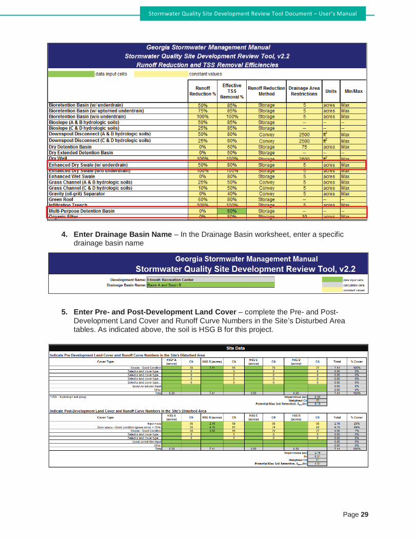
Page 29
Stormwater Quality Site Development Review Tool Document – User’s Manual
4. Enter Drainage Basin Name – In the Drainage Basin worksheet, enter a specificdrainage basin name
5. Enter Pre- and Post-Development Land Cover – complete the Pre- and Post-
Development Land Cover and Runoff Curve Numbers in the Site’s Disturbed Areatables. As indicated above, the soil is HSG B for this project.

Page 30
Stormwater Quality Site Development Review Tool Document – User’s Manual
6. Select Conservation Area Credits, if applicable – There is a 0.5-acre conservation
area credit associated with this project because 0.5 acres is being left in its naturalcondition, and a conservation easement has been issued for the area. Select theScenario 1 box and input 0.5 in the input cell (cell A50).
7. Enter the Target Runoff Reduction Storm (in) – The default value in cell C64 is oneinch, which is the correct target runoff reduction storm for this project.
8. Enter the BMP(s) Data – See Appendix B2 of the Manual for sizing steps. Complete the
Select BMPs for Runoff Reduction and Water Quality table.

Page 31
Stormwater Quality Site Development Review Tool Document – User’s Manual
The Tool indicates that the target water quality goal has been met.
9. Enter the target rainfall events – The target rainfall events were provided in the project
information. Enter the values in row 106.
Utilize the adjusted curve number and the modified TR-55 approach to compute the channel protection storage volume (CPv) and Overbank Flood Protection Volume (Qp25).
10. Provide comments – Suggest indicating references to the conservation easement and
multi-purpose detention basin TSS Removal % in the stormwater report.

Page 32
Stormwater Quality Site Development Review Tool Document – User’s Manual
Frequently Asked Questions 6.0
What does “Impervious Cover” mean? Impervious cover refers to land cover that is impermeable to runoff, and includes all paved surfaces. In addition, any surface that supports vehicle traffic, such as a gravel road or parking lot, is considered impervious.
Are Green Roofs and Permeable Pavement pervious or impervious? Green roofs and permeable pavement are partially impervious. These practices act as a runoff
reduction and stormwater treatment practice, so that the ultimate runoff from these surfaces is reduced. For the purposes of the Tool, however, the area of permeable pavement and green roofs should be included as impervious area.
Can I direct additional impervious drainage to permeable pavement? While the worksheet allows the user to enter a drainage area greater than the pavement area, the GSMM does not recommend this practice and it is discouraged. Doing so in practice could increase maintenance burden and/or lead to failure of the permeable pavement system.
How should I use the “Channel and Flood Protection Calculations” section? The “Channel and Flood Protection Calculations” section generates revised curve numbers that account for the benefits of runoff reduction practices. Detention is typically not needed if the revised curve number is lower than the pre-developed curve number. If detention is needed, a hydrologic and hydraulic analysis will be needed to properly size and route flow through the practice.
As a reviewer, what are some key cells I should look at to ensure that the submitted worksheet is accurate? Some checks that can help to act as a “first screen” to ensure that the spreadsheet has been used correctly include the following: Runoff Reduction and TSS Removal Efficiencies Worksheet
1) Verify user input values, if applicable. Backup information should be provided by theuser to support their inputs.
Drainage Basin Worksheets 2) Thoroughly check the Conservation Area Credit section. Verify that the area is protected
by a conservation easement or equivalent form of protection.3) Check drainage areas to each BMP and their storage volumes, if applicable, to ensure
that practices capture the design volume. For each drainage basin the total of thepervious and impervious area draining to BMPs should be less than or equal to the totaldrainage basin pervious and impervious area.
4) For permeable pavement and bioretention, ensure that the designer has selected“underdrained” if an underdrain is needed.
5) Review the site plan to ensure that the pathway of practices in series from the“Downstream BMP” (column H) corresponds to the actual conditions.
Why don’t I need to enter a storage volume for some practices? Some practices, such as bioretention basins, are credited based on their storage volume Other practices, such as rooftop disconnection, receive credit based on meeting a minimum design standard that conveys a runoff volume.

Page 33
Stormwater Quality Site Development Review Tool Document – User’s Manual
How should I credit underground storage? The default Underground Detention BMP does not provide any runoff reduction or TSS removal credits. If it does not provide infiltration it will not provide treatment or runoff reduction, and will act as a detention practice only. If underground storage is designed, however, to provide infiltration, it can act as an infiltration practice. This can be input into the tool as a User Input, if necessary.
How do I account for BMPs that have an upturned underdrain if it is not listed in the Runoff Reduction and TSS Removal Efficiencies worksheet? The three User Input options at the bottom of the table in the Runoff Reduction and TSS Removal Efficiencies table can be used to account for BMPs that have an upturned underdrain and are not already included in the worksheet.
Does the worksheet allow me to do anything that is inconsistent with the guidance in the GSMM? Yes. The worksheet is only intended as a tool to quantify the runoff reduction and treatment volume provided on site, and does not have limits on design parameters. For example, drainage areas are not limited, and practices that may require an underdrain on C or D soils can be applied on sites that have only C and D soils. When doing anything that is or appears to be inconsistent with the GSMM, consult the local jurisdiction for further guidance.
I have a pond that captures drainage from several upstream practices. For the drainage area to the pond, should I enter the entire drainage area, or only the land that has not been captured by other practices? Only enter the remaining drainage area. The overflow from upstream practices will be accounted for as the “Volume Received by Upstream Practices.”
Are runoff volumes generated from off-site areas allowed in the volume runoff reductions? Because off-site areas can change over time with no input from the owner/developer of the property in question, volumes generated from off-site areas can be routed through a BMP, but no water quality credits will be achieved for the off-site volumes.
How are these “drainage basin” areas defined in terms of areas used in water quality, channel protection, and peak flows? Do the drainage basin areas treat areas outside the site differently? In terms of water quality, a drainage basin in the Tool only takes into account the on-site area. The channel protection volume and peak flows are dependent on the specific conditions of the site and where the analysis point is located.

Columbia County, Georgia Supplement to the GSMM Page 28
Appendix #2: Inspection and Maintenance Agreement
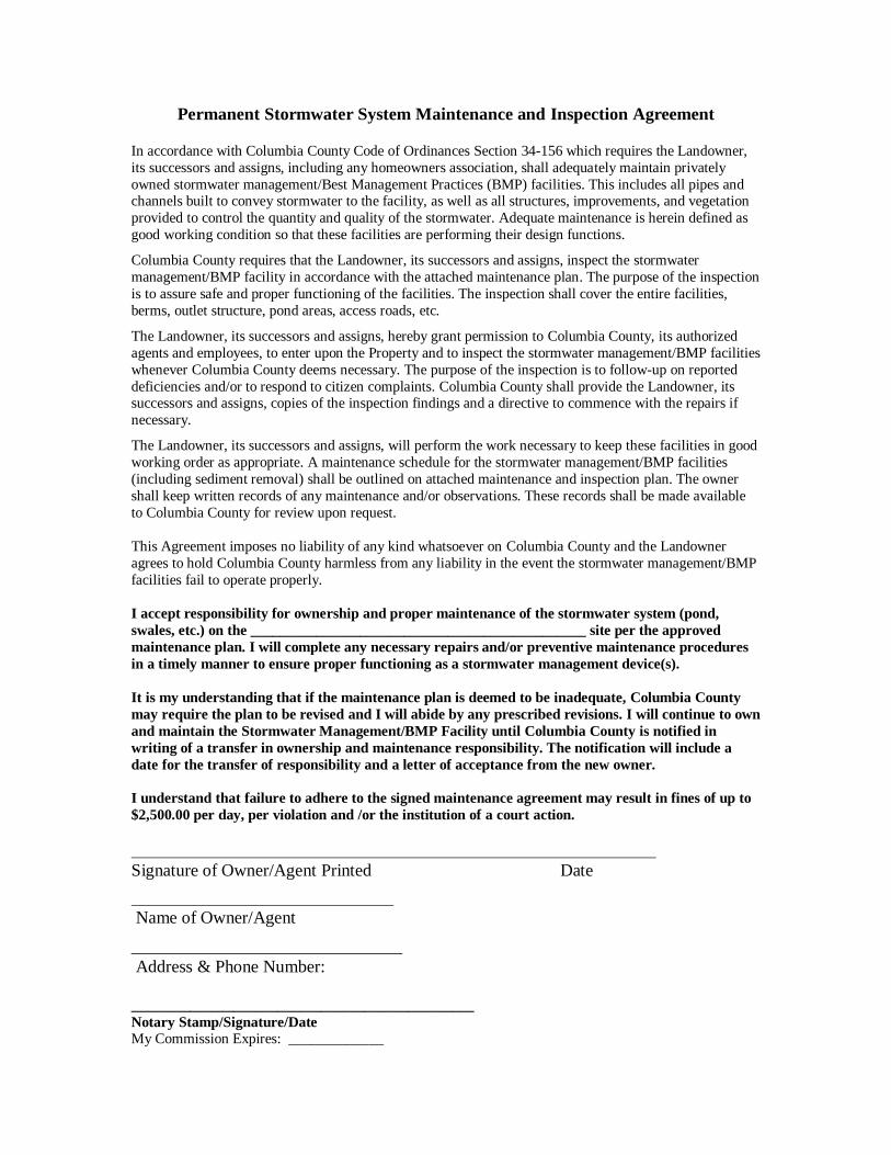
Permanent Stormwater System Maintenance and Inspection Agreement
In accordance with Columbia County Code of Ordinances Section 34-156 which requires the Landowner,
its successors and assigns, including any homeowners association, shall adequately maintain privately
owned stormwater management/Best Management Practices (BMP) facilities. This includes all pipes and channels built to convey stormwater to the facility, as well as all structures, improvements, and vegetation
provided to control the quantity and quality of the stormwater. Adequate maintenance is herein defined as
good working condition so that these facilities are performing their design functions.
Columbia County requires that the Landowner, its successors and assigns, inspect the stormwater
management/BMP facility in accordance with the attached maintenance plan. The purpose of the inspection
is to assure safe and proper functioning of the facilities. The inspection shall cover the entire facilities,
berms, outlet structure, pond areas, access roads, etc.
The Landowner, its successors and assigns, hereby grant permission to Columbia County, its authorized
agents and employees, to enter upon the Property and to inspect the stormwater management/BMP facilities
whenever Columbia County deems necessary. The purpose of the inspection is to follow-up on reported
deficiencies and/or to respond to citizen complaints. Columbia County shall provide the Landowner, its successors and assigns, copies of the inspection findings and a directive to commence with the repairs if
necessary.
The Landowner, its successors and assigns, will perform the work necessary to keep these facilities in good
working order as appropriate. A maintenance schedule for the stormwater management/BMP facilities
(including sediment removal) shall be outlined on attached maintenance and inspection plan. The owner
shall keep written records of any maintenance and/or observations. These records shall be made available
to Columbia County for review upon request.
This Agreement imposes no liability of any kind whatsoever on Columbia County and the Landowner
agrees to hold Columbia County harmless from any liability in the event the stormwater management/BMP
facilities fail to operate properly.
I accept responsibility for ownership and proper maintenance of the stormwater system (pond,
swales, etc.) on the ______________________________________________ site per the approved
maintenance plan. I will complete any necessary repairs and/or preventive maintenance procedures
in a timely manner to ensure proper functioning as a stormwater management device(s).
It is my understanding that if the maintenance plan is deemed to be inadequate, Columbia County
may require the plan to be revised and I will abide by any prescribed revisions. I will continue to own
and maintain the Stormwater Management/BMP Facility until Columbia County is notified in
writing of a transfer in ownership and maintenance responsibility. The notification will include a
date for the transfer of responsibility and a letter of acceptance from the new owner.
I understand that failure to adhere to the signed maintenance agreement may result in fines of up to
$2,500.00 per day, per violation and /or the institution of a court action.
Signature of Owner/Agent Printed Date
Name of Owner/Agent
_______________________________
Address & Phone Number:
_______________________________________________
Notary Stamp/Signature/Date
My Commission Expires: _____________

Columbia County, Georgia Supplement to the GSMM Page 29
Appendix #3: Greenspace Deed and Covenants

EXHIBIT ''B"
DECLARATION OF COVENANTS AND RESTRICTIONS
WHEREAS, Grantor and Grantee mutually desire that the Property be used in perpetuity as Greenspace property as provided in O.C.G.A. §§ 12-6A-1 et seq./ and
NOW THEREFORE, in consideration of the mutual benefit to the parties hereto, the general public, and the environment of Columbia County, Georgia, Granter and Grantee hereby place certain restrictions on the Property exclusively for conservation purposes, in order that it shall remain substantially in its open, natural and scenic condition in perpetuity, as follows:
1.
The terms and conditions of this Declaration of Covenants and Restrictions shall be both implicitly and explicitly included in any subsequent transfer, conveyance, or encumbrance affecting a11 or any part of the Property. Any subsequent transfer, conveyance or encumbrance shall either set forth the terms and conditions of this document in full or by reference to this document and its recorded location.
2.
The Property shall be used in perpetuity as Greenspace property as provided in O.C.G.A. §§ 12- 6A-1 et seq.
3.
This covenant shall be binding upon the Grantee, its heirs, successors and assigns, and upon occupiers or users of the Prope1iy forever. This covenant shall not terminate upon some fixed amount of time, but shall run with the land both as to benefit and as to burden. This covenant is established as a conservation benefit to the general public for the purpose of preserving greenspace and shall run in perpetuity as provided in O.C.G.A. § 44-5-60(c).

EXHIBIT "A"
Legal Description

ACCEPTANCE BY COUNTY
The forgoing Quitclaim Deed & Declaration of Greenspace Covenants and Restrictions is hereby accepted by Columbia County.
Dated ,20 .
COLUMBIA COUNTY, GEORGIA: By (Print):
Its Chairman of the Board of Commissioners

EXECUTED under seal as of the day and year first above written.
Signed, sealed and delivered in our presence in Columbia County, Georgia:
Witness Notary Public, County, Georgia. My commission expires:
(SEAL)
GRANTOR: By (Print): As Its ATTEST: By (Print): As Its
(SEAL)

STATE OF GEORGIA QUITCLAIM DEED &
DECLARATION OF GREENSPACE COUNTY OF COLUMBIA COVENANTS & RESTRICTIONS
THIS INDENTURE made and entered into this day of , 20 ,
between , a Georgia Corporation AND ,
, a Georgia Corporation (hereinafter referred to as "Grantor") and COLUMBIA COUNTY, GEORGIA, a political subdivision of the State of Georgia (hereinafter referred to as "Grantee") ("Grantor" and "Grantee" to include their respective heirs, successors, executors, administrators, legal representatives and assigns where the context requires or permits).
W I T N E S S E T H
THAT the Grantor, for and in consideration of ONE AND NO/ l 00 DOLLARS ($1.00), and
other good and valuable consideration by the Grantee, the receipt and adequacy of which arehereby acknowledged, have bargained, granted, sold, aliened, conveyed and confirmed, and by these presents do bargain, grant, sell, alien, convey and confirm unto the Grantee all its interest, if any, in the property, and all improvement thereon, described on Exhibit " A" attached hereto and by reference made a part hereof, ("Property") subject to certain restrictions placed upon the Property by this indenture, as fully set forth in Exhibit "B", attached hereto and incorporated herein.
TO HAVE AND TO HOLD the Property, with all and singular the rights, members and
appurtenances thereof, to the same being, belonging, or in anywise appertaining, to the only proper use, benefit and behoof of Grantee forever in FEE SIMPLE.

Columbia County, Georgia Supplement to the GSMM Page 30
Appendix #4: Indemnity Statement

INDEMNITY STATEMENT
WHEREAS, _____________________________________________has submitted a Land Disturbance Applicaion to Columbia County, Georgia, in connection with proposed construction and/or development;
and
WHEREAS, a stormwater management facility is required for the proposed development; and
WHEREAS, _____________________________________________does not desire to erect a
fence around the stormwater management facility.
NOW, THEREFORE, in consideration of Columbia County, Georgia, not requiring a fence to be
constructed in compliance with Columbia County, Georgia requirements around the stormwater management facility in the aforementioned proposed development,____________________________________ shall indemnify and save harmless Columbia County,
Georgia, the Columbia County Board of Commission, and their employees, agents, elected officials and
officers, against any and all damages to property or injuries to or death of any person or persons, and
shall defend, indemnify and save harmless Columbia County, Georgia, the Columbia County Board of Commission, and their employees, agents, elected officials and officers, from any and all claims,
demands, suits, actions or proceedings of any kind of nature, of or by anyone whomsoever, in any way
resulting from or arising out of Columbia County, Georgia, approving said proposed development dated,
_______________, 20__________, and submitted by ___________________________________
without a fence constructed in accordance with Columbia County, Georgia requirements for the
stormwater management facility on the proposed development. This property is shown on a plat which is
recorded in the office of the Clerk of Superior Court of Columbia County, Georgia, in PC- ________ Slide ________ .
This Indemnity Agreement is binding on the successors and/or assigns of
___________________________________ who agrees that should the property be sold, a copy of this
Indemnity Agreement will be made a part of the closing documentation and shall be transferred at closing
to the successor or assignee of ___________________________________.
Reference to this Indemnity Agreement shall be placed on the Final Plat for the construction and /or
development.
Signed, Sealed and Delivered
This _____ day of ____________________, 20_____
in the presence of :
______________________________ ______________________________
Witness Witness
______________________________
Owner/Developer
______________________________ Commission Expires:_____________
Notary Public

Columbia County, Georgia Supplement to the GSMM Page 31
Appendix #5: Memo from Georgia EPD Regarding “Roadway Drainage Structures”


Columbia County, Georgia Supplement to the GSMM Page 32
Appendix #6: Memo from Georgia EPD Regarding “Dams Located in Buffers”


Columbia County, Georgia Supplement to the GSMM Page 33
Appendix #7: Memo from Georgia EPD Regarding “Minor Land Disturbing Activities”

Page 1
April 2017
MINOR LAND-DISTURBING ACTIVITIES
The intent of this document is to clarify minor land-disturbing activities as defined in GESA and the
NPDES General Permits for Storm Water Discharges Associated with Construction Activity Common
Development and Stand Alone Permits, as follows:
A. As per O.C.G.A. 12-7-17(3), minor land-disturbing activities are exempt from the Georgia Erosion
and Sedimentation Act (GESA): “Such minor land-disturbing activities as home gardens and
individual home landscaping, repairs, maintenance work, fences, and other related activities
which result in minor soil erosion.”
The following land-disturbing activities are examples of projects not specifically listed in O.C.G.A.
12-7-17(3) that would be considered minor land-disturbing activities and therefore, exempt from
GESA and the applicable buffer requirements for State waters:
1. Structures including, but not limited to decks, patios, gazebos, walkways, viewing platforms,
picnic shelters, fire pits, BBQ pits, and sign kiosks, provided:
a. The encroachment into the buffer is 100 square feet or less,
b. Disturbance of existing buffer vegetation is minimized, and
c. The site is stabilized at the end of each day with temporary or permanent stabilization
measures until project completion.
2. Placement of rip rap, provided:
a. Project is 100 linear feet or less of rip rap,
b. Total amount of rip rap allowed in the buffer is 1000 square feet,
c. Disturbance of existing buffer vegetation is minimized, and
d. The site is stabilized at the end of each day with temporary or permanent stabilization
measures until project completion.

[Type text]
Page 2
April 2017
B. As per Part1(C)(1)(c), minor land-disturbing activities are exempt from coverage under the NPDES
General Permits for Storm Water Discharges Associated with Construction Activity Common
Development and Stand Alone Permits (Permit), “coverage under this permit is not required for
discharges of storm water associated with minor land-disturbing activities (such as home
gardens and individual home landscaping, repairs, maintenance work, fences and other
related activities which result in minor soil erosion conducted outside of the 25 foot buffer
along the banks of all State Waters requiring a buffer and outside of the 50 foot buffer along
the banks of all State waters classified as “trout streams” requiring a buffer…”:
The following land-disturbing activities are examples of projects not specifically listed in
Part1(C)(1)(c) of the NPDES General Permits for Storm Water Discharges Associated with
Construction Activity Common Development and Stand Alone Permits that would be considered
minor land-disturbing activities and therefore, exempt from coverage under the NPDES General
Permit:
1. Structures including, but not limited to decks, patios, gazebos, walkways, viewing platforms,
picnic shelters, fire pits, BBQ pits, and sign kiosks, provided:
a. The residential lot is occupied by an individual homeowner and has been completed and
undergone final stabilization as per the Permit,
b. The activity is conducted outside the 25 and/or 50 foot State mandated buffers,
c. The project area is 100 square feet or less,
d. Disturbance of existing vegetation is minimized, and
e. The site is stabilized at the end of each day with temporary or permanent stabilization
measures until project completion.

Columbia County, Georgia Supplement to the GSMM Page 34
Appendix #8: Memo from Georgia EPD Regarding “State Waters Issues”


Columbia County, Georgia Supplement to the GSMM Page 35
Appendix #9: Columbia County SOP for State Waters Determinations

Columbia County Stormwater Utility
Standard Operation Procedure for State Waters Determinations
1. Prior to conceptual design plan or site plan submittal, the site developer or his
representative shall contact the Columbia County Stormwater Utility Department to
schedule a site visit, providing parcel number and preliminary project sketch, if
available.
2. Stormwater Staff shall walk the site with the developer or with his representative to
mark, using visible flagging, all buffered and unbuffered State Waters. The “Field
Guide for Determining the Presence of State Waters that Require a Buffer,”
published by the Georgia Department of Natural Resources shall be used for
guidance in the determination.
3. The developer shall submit an “Environmentally Sensitive Areas Plan” showing:
a. Project area,
b. Topography,
c. State Waters as determined by the aforementioned site visit,
d. Delineated wetlands, and
e. Special flood hazard area.
Said plan shall be included as part of the conceptual design plan or site plan
submittal.
4. The Columbia County Stormwater Utility Department will issue a formal State
Waters Determination Letter referencing the data shown on the “Environmentally
Sensitive Areas Plan,” which shall remain valid for a period of 12 months (1 year).
5. All preliminary plats and site plans shall contain a notation on each Erosion
Sedimentation and Pollution Control plan sheet stating, “The state waters shown on
this plan have been field verified by Columbia County as a Local Issuing Authority in
Georgia on (date).”

Columbia County, Georgia Supplement to the GSMM Page 36
SPECIFICATIONS

Columbia County, Georgia Supplement to the GSMM Page 37
Section 16.0: Construction of Storm Drain Pipe Systems

16.0 CONSTRUCTION OF STORM DRAIN PIPE SYSTEM
16.0 Description The work covered by this section of the specifications consists of furnishing and in performing all operations, necessary and incidental to the construction and installation of storm drain pipe. This shall include, but not be limited to all excavation, trenching, removal and replacement of unsuitable materials, grading, all pipe and fittings, as shown on the plans or drawings.
16.1 Plans, Permits and Codes 16.1.1 Permits and Codes
It is the intent of this section of this section of the specifications that the contractor’s bid on this work be based upon the plan, drawings and these specifications and with all applicable codes, permits and regulations as amended by any waivers.
16.1.2 Plans A. The contract drawings, standard drawings and plans indicate the
extent and specific arrangement of the work. B. If any departures from the indicated line grade or location as shown
by the plans are deemed necessary by the contractor, details of such departures and the reasons therefore shall be submitted as soon as practicable for approval.
C. No work on such departures or deviations shall begin without written approval. No work shall be accepted by the Stormwater Department with any unapproved departures or deviations from the contract drawings, standard drawings or plan.
16.2 Materials 16.2.1 General
A. All materials furnished by the contractor shall meet the requirements and these specifications.
B. All materials shall be new, first quality and free from any and all defects and blemishes such as cracking, splitting, spalling, damages to coatings, bending, dents and deformations of any type. Material shall be protected from damage at all times.
C. The materials may be inspected at any time and all material deemed unsuitable or damaged, shall be removed from the right of way, easement or limits of construction.
D. Extreme care shall be exercised in handling the material during unloading and stringing and at all times during construction. All unloading or placing of pipe in the trench shall be done carefully by hand or machine. At no time will materials be allowed to free fall or be dropped from any height.
Columbia County, Georgia Construction Standards & Specifications 16.0 Construction of Storm Drain Pipe System Page 16-1

16.2.2 Pipe Specifications Except as otherwise approved, pipe for storm drains shall be reinforced concrete or PP (in limited applications per GADOT for all applications within the public right of way. Reinforced concrete pipe, smooth-lined corrugated polyethylene (PE) culvert pipe, or double walled high density polyethylene pipe (HDPE) may be used for all other applications. A. Reinforced Concrete Pipe:
1. Reinforced concrete pipe shall meet the requirements of ASTM C-76, of the latest edition and the class of pipe to be determined by the Design Engineer. “O” Ring gasket pipe shall be used in the roadway while tongue and groove pipe will be allowed outside the roadway but within the right of way.
2. Minimum pipe size shall be 18 inches. B. Smooth-lined, Corrugated Polyethylene (PE) Culvert Pipe:
1. Polyethylene storm drainage pipe shall conform to AASHTO M294. 2. Type S for 18" to 36" sizes and AASHTO MP6-95 Type S for 42" and
48" diameters. C. High Density Polyethylene Pipe (HDPE):
1. Smooth interior Type “S” or Type “D” in conformance with ASSHTO specifications M-252, M-294, and MP6-95. Installation of HDPE pipe must be in conformance with ASTM D 2321.
D. Polypropylene (PP) Pipe: 1. PP shall have smooth interior and annular exterior corrugations
and meet or exceed ASTM F2881 and AASHTO M330. 16.2.3 Fittings and Bands
All fittings and bands shall be factory produced first quality and shall be designed for installation on the pipe to be used and be of the same quality and material as the pipe to be used. The fittings and couplings shall comply with the joint performance criteria of AASHTO Standard Specifications for Highway Bridges, Division II.
16.2.4 Affidavit of Compliance The contractor shall furnish an affidavit from the manufacturer that all material conforms to the above referenced ASTM or AASHTO Specifications to the County Engineer upon request.
16.2.5 Weep Holes Weep hole pipe shall be minimum schedule 40 PVC meeting ASTM D1785 Standard Specification for Poly Vinyl Chloride (PVC) Plastic Pipe, Schedules 40, 80, and 120 or D2665 Standard Specification for Poly Vinyl Chloride (PVC) Plastic Drain, Waste, and Vent Pipe and Fittings.
16.3 Excavation Excavation and trenching shall be in accordance with Section 11.1 to 11.4.2.3 inclusive.
Columbia County, Georgia Construction Standards & Specifications 16.0 Construction of Storm Drain Pipe System Page 16-2

16.3.1 Trenching A. All construction must meet or exceed OSHA Standards. The installation of
suitable sheeting protect adjoining poles, roadways, utilities, and private property when, in the opinion of the county personnel, trench excavation may damage these structures. Such orders or lack thereof shall in no way relieve the contractor from the responsibility of protecting these structures.
B. Trench excavation shall not advance more than 200 feet ahead of pipe installation without prior approval. The bottom of all trenches shall be smooth and flat and with backfill material affording full bearing of the pipe barrel. The depth and width required shall be as specified in the design documents.
C. Bell holes shall be excavated in a manner that relieves pipe bells of all loads and ensures support throughout the length of the pipe barrel.
D. Excavation in excess of the depths required for manholes and other structures shall be corrected by placing a sub foundation of #57 stone, surge stone or some combination thereof.
E. No trench shall be left open overnight. Backfilled trenches shall be stabilized with seed and mulch by the end of each day
16.3.2 Subgrade Stabilization Where, in the opinion of the county personnel, subgrade is too soft and/or excessively wet for proper pipe installation, the county personnel may order the contractor to undercut the ditch and backfill with #57 stone to grade.
16.3.3 Bedding A. Trenches shall have been excavated accurately to plan grade to
provide a uniform and stable foundation. B. A maximum overcut of 6 inch shall be allowed. C. Materials of poor or non-uniform bearing capacity shall be removed
and replaced with suitable material. D. Rock shall be excavated to a depth of 6 inches below plan grade and
suitable bedding placed. E. For PE, HDPE and PP, a uniform blanket of graded aggregate material
shall cover the bedding to a depth sufficient to allow the corrugations to become filled with material.
F. Bedding or shaping shall be wide enough to permit efficient compaction of the remaining backfill under the haunches of the structure, but not so wide as to interfere with bolting procedures.
16.3.4 Backfill A. After pipe is laid in the prepared trench bottom, bedding as previously
specified shall be placed and compacted under the pipe haunches to the center of the pipe and carefully compacted by hand.
Columbia County, Georgia Construction Standards & Specifications 16.0 Construction of Storm Drain Pipe System Page 16-3

B. Only sufficient material to backfill to the centerline of the pipe shall be placed in the ditch and compacted until satisfactory compaction has been attained.
C. When haunch compaction is attained, the contractor shall begin backfill of the trench, placing material symmetrically so as to prevent eccentric loading or wedge action against the pipe. 1. On RCP placed within the right of way, Class I, II or III backfill shall
be placed in lifts of no more than 8 inches loose and compacted by mechanical tampers to 100% maximum dry density, standard proctor.
2. PP and HDPE shall be backfilled with graded aggregate material meeting GDOT specifications with the following restrictions:
a) 20 foot maximum fill height for HDPE, and b) 25 foot maximum fill height for PP
D. No material which has previously disapproved or found unsuitable, or is wet or frozen or contains mulch or other organic perishable material of any description, large stones, blasted rock, broken concrete or pavement, or other hard materials having any dimensions greater than 2 inches; Clods of earth or dirt larger in any dimension greater than 2 inches, debris or earth with an exceptionally high void or clay content shall be placed as backfill in any trench.
16.4 Construction 16.4.1 Pipe Laying
A. Only such pipe as has been previously inspected and approved, is free of dents, spalls, cracks and is free from any damage which may, be detrimental to the proper functioning of the storm drain system, shall be laid in the trench.
B. The contractor shall remove from the site all damaged material. C. Pipe shall be carefully lowered into the trench; no pipe shall be free
dropped into the trench. D. The pipe laying shall precede upgrade with the spigot end of bell and
spigot pipe pointing in the direction of the flow. E. Each pipe shall be laid true to line and grade in such manner as to
form a close concentric joint with the adjacent pipe and to prevent offsets in the flow line.
F. The pipe shall be kept clean and free of debris at all times.
16.4.2 Jointing A. Reinforced concrete pipe sections may be joined by mortar joints,
bituminous plastic cement joints, rubber type gasket joints, O-Ringed gasket joints or preformed plastic gasket joints. In mortar and bituminous plastic cement joints the annular space shall be filled with
Columbia County, Georgia Construction Standards & Specifications 16.0 Construction of Storm Drain Pipe System Page 16-4

the joint material and the inside of the joint wiped smooth. Mortar joints shall be made in the same manner except that the annular space shall be thoroughly wetted before filling with joint material. After the initial wet, the mortar on the outside shall be protected from the air and sun with thoroughly wet cover.
B. HDPE shall be watertight according to the requirements of ASTM D3212. Gaskets shall meet the requirements of ASTM F477. Gaskets shall be installed by the pipe manufacturer and covered with a removable, protective wrap to ensure the gasket is free from debris. A joint lubricant available from the manufacturer shall be used on the gasket and bell during assembly. Joints diameters shall have an exterior bell wrap installed by the manufacturer.
C. PP shall be joined with a gasket, integral bell and spigot joint, meeting the requirements of ASTM F2881. Joints shall be watertight according to the requirements of ASTM D3212. Spigots shall have gaskets meeting the requirements of ASTM F477. Gasket shall be installed by the pipe manufacturer and covered with a removable, protective wrap to ensure the gasket is free from debris. A joint lubricant available from the manufacturer shall be used on the gasket and bell during joint assembly. Joints shall have an exterior bell wrap installed by the manufacturer.
16.4.3 Dewatering A. All grading in the vicinity of trench excavations shall be controlled to
prevent surface ground water from flowing into the trenches. B. When water seepage within the trench or ground water level creates
unstable foundation conditions or prevents the proper makeup of joints, the water shall be removed by well pointing, pumping or other suitable means.
C. Water so removed shall be discharged in a manner and location so as not to cause injury or damage to public or private property, work in progress or completed work.
16.4.4 Blasting Blasting shall be performed in accordance with Section 11.9 of these specifications.
16.5 Tie-in to Existing Storm Drains 16.5.1 Authorization
A. At no time shall the contractor make any unauthorized tie-ins of storm drains of any type under construction to existing storm drains of any type.
B. The contractor shall not make any authorized tie-ins (e.g. called for on the plans or previously approved changes) unless the County Engineer is present.
Columbia County, Georgia Construction Standards & Specifications 16.0 Construction of Storm Drain Pipe System Page 16-5

16.5.2 Construction A. The contractor shall make any such tie-ins in close accordance with
the plans. B. The contractor shall take whatever measures are necessary to
prevent the introduction of mud, silt, debris or excess surface water runoff into the existing storm drain system.
C. Expediting Work-The contractor shall excavate, lay the pipe, and backfill as closely together as possible. Unjointed pipe shall not be left in the trench overnight. The contractor shall backfill and compact the trench as soon as possible after laying and jointing is completed. The exposed end of the installed pipe shall be covered with plywood or filter fabric each day at the close of work and at all other times when work is not in progress. If necessary to backfill over the end of an uncompleted pipe, the end shall be closed with a mechanical joint plug, however, backfilling shall commence only after inspection.
16.6 Field Tests A. Pipe and Fittings:
Each piece of pipe and fitting shall be visually inspected by county personnel immediately before being placed in the trench and all pieces which are damaged and cannot be repaired after installation shall be rejected.
B. Joints Alignment and Grade: 1. After the pipe has been installed in the trench and prior to
backfill, the joints alignment and grade shall be carefully checked for conformance with the plans.
2. Any deposit or protruding joint material shall be removed and the joint remade.
C. Visual Inspection: All storm drains shall be visually checked for alignment between structures and any deviations from the plan line and grade or offsets of any type shall cause that portion of the storm drain system to be rejected if said defects will adversely affect the designed performance of the system and shall be re-laid correctly by the contractor at the contractor’s expense.
16.7 Protection of Service Lines and Utilities Protection of service lines and utilities shall be in accordance with Section 1.11 of these specifications.
16.8 Restoration of Property Restoration of property shall be in accordance with Section 1.12 of these specifications.
16.9 Removal and Replacement of Existing Pipes and Equipment Removal and replacement of existing pipes and equipment shall be in accordance
Columbia County, Georgia Construction Standards & Specifications 16.0 Construction of Storm Drain Pipe System Page 16-6
with Section 11.14 of these specifications.
16.10 Pavement Removal and Replacement Pavement removal and replacement shall be in accordance with Section 11.15 of these specifications.
16.11 Clean Up and Finishing 16.11.1 Clean Up
All pipes shall be clean and free from silt, mud, debris or anything which may block the free flow of water prior to acceptance.
16.11.2 Finishing Finishing shall be in accordance with Section 11.16 of these specifications.
16.12 Grassing Grassing shall be performed in accordance with Section 20 of these specifications.
16.13 Safety Safety procedures shall be is accordance with Section 12.16 of these specifications.
16.14 Measurement and Payment Measurement and payment for storm drain pipe shall be by the linear foot for each type and size listed in the Summary of Quantities complete in place and accepted by the County Engineer. Said payment shall be considered full and just recompense for all materials, equipment, labor, excavation, backfill and anything required of any description for the satisfactory completion of the work described or called for by this section of the specifications not specifically noted as a pay item in the Summary of Quantities.
Columbia County, Georgia Construction Standards & Specifications 16.0 Construction of Storm Drain Pipe System Page 16-7

Columbia County, Georgia Supplement to the GSMM Page 38
Section 17.0: Construction of Open Drainage Systems

Columbia County, Georgia Construction Standards & Specifications 17.0 Construction of Open Drainage System Page 17‐1
17.0 CONSTRUCTION OF OPEN DRAINAGE SYSTEMS
17.1 Description The work covered by this section of the specifications consists of furnishing all labor, the construction and installation of open storm drain systems. This shall include, but n ot be limited to all excavation, trenching, removal and replacement of unsuitable materials and grading as shown of the plans or drawings.
17.2 Plans, Permits and Codes
17.2.1 Permits and Codes It is the intent of this section of the specifications that the contractor’s bid on this work be based upon the plans, drawings, and these specifications and with all applicable codes, permits and regulations as amended by any waivers.
17.2.2 Contract Drawings A. Standard drawings and plans indicated the extent and specific
arrangement of the work. Swales and ditches in additional locations may be required by the County Engineer.
B. If any departures from t he indicated l i ne, grade or locat ions as shown by the plans are deemed necessary by the contractor, details of such departures and the reasons therefore shall be submitted as soon as practicable for approval.
C. No work on such departures or deviations shall begin without written approval by the Stormwater Dept. No work shall be accepted by the Stormwater Department with any unapproved departures or deviations from the contract drawings, standard drawings or plans.
17.3 Material
17.3.1 General All materials shall be new, first quality, undamaged material meeting these specifications.
17.3.2 Concrete A. All concrete shall be in accordance with Section 8 of
these specifications except as herein specified. B. Concrete shall have a compressive strength at 28 days of 3000 psi. C. The maximum size of coarse aggregate shall be 1 inch and not less
than 1 inch. Concrete shall have a slump of not more than 3 inches.
17.3.3 Reinforcing Wire Reinforcing wire shall be 6” X 6” #10 wires.
17.3.4 Expansion Joint Material Expansion joint material shall conform to ASTM Standard D‐1751 or

Columbia County, Georgia Construction Standards & Specifications 17.0 Construction of Open Drainage System Page 17‐2
D‐ 1752 or latest edition or shall be resin impregnated fiber board conforming to the physical requirements of D‐1752.
17.4 Construction of Ditches and Swales
17.4.1 Line and Grade A l l d i t c h e s a n d s w a l e s s h a l l b e c o n s t r u c t e d t r u e t o p l a n l i n e a n d g r a d e .
17.4.2 Cross Section T h e d i t c h or s w a l e s h a l l b e c o n s t r u c t e d a s i n d i c a t e d on t h e p l a n d r a w i n g s .
17.4.3 Ditch Checks A. Ditch checks shall be constructed at intervals conforming to
recommendations in the Manual for Erosion and Sediment Control in Georgia.
B. Ditch checks shall be constructed of stone rip‐rap or sand cement bags placed by hand. Placement shall be in accordance with Standard Drawing 17.1.
17.5 Construction of Concrete Ditches
17.5.1 Excavation The sub‐base shall be excavated true to line and grade by appropriate equipment.
17.5.2 Preparation of Sub‐Base A. Prior to forming or pouring concrete, the sub‐base shall be of a
smooth and uniform texture and compacted to 100% maximum dry density, standard proctor.
B. The centerline shall conform to the established elevations with an acceptable tolerance of plus/minus 1/ 2 ”. The acceptable tolerance under a template shall be plus/minus 1/4”.
17.5.3 Forms A. Forms shall be of wood or steel, straight and true without
any defects which may adversely affect the work. B. Forms shall be held rigidly in place by the use of stakes placed
no more than four (4) feet apart. C. Rigid forms shall be used in all circumstances except that benders
and thin wall planks may be used with the prior approval of the county personnel.
D. Forms shall not be removed for six (6) hours or in any case while the concrete is sufficiently plastic to slump in any direction.
E. Forms shall be thoroughly cleaned and oiled prior to each use.
17.5.4 Joints A. Pre‐molded expansion joint filler strips shall be resilient,
compressive bituminous and fiber material saturated with at least

Columbia County, Georgia Construction Standards & Specifications 17.0 Construction of Open Drainage System Page 17‐3
35%, but not over 50%, by weight of asphalt. B. Expansion joints shall be cut to the full depth of the cross
section of the ditch and shall extend no further than 1/4” below the level surface of the ditch.
C. Expansion joints at least 1/4” in width shall be provided in the ditch at intervals not to exceed 50 feet and an expansion joint of at least 1/2” in width where ditches abut structures.
D. Contraction joints of 1/8” in width shall be spaced at 10’ intervals.
E. The depth of the contraction joint shall be no less than 1/5” or
more than 1/4" the depth of the concrete and joints shall have rounded edges.
F. Separators shall be removed as soon as possible after the concrete has set sufficiently to preserve the width and shape of the joint.
17.6 Concrete
A. No concrete shall be placed until the sub‐base has been approved by the County Personnel.
B. No concrete shall be placed when the ambient air temperature is below 40 degrees F. (4 degrees C).
C. Concrete shall be placed in forms to the required depth and thoroughly consolidated by tamping and spading so that there are no rock and air pockets at forms and mortar entirely covers the surfaces. Concrete shall not be free dropped from a height so as to cause segregation.
D. The concrete ditch shall be constructed in accordance with Standard 17.02.
E. Visible surfaces and edges of the finished ditch shall be free of blemishes, form and tool marks.
F. Concrete ditches shall be finished in accordance with Section 11.054 of these specifications.
17.7 Unsuitable Sub‐Base In areas where the sub‐base is otherwise unsuitable the contractor shall place reinforcing wire and additional thickness of concrete as required and/or replace the unsuitable material in accordance with Section 11.5.4 of these specifications, at the discretion of the County Personnel.
17.8 Finishing and Protection
17.8.1 Backfill After the concrete has cured for at least seven days, all debris shall be removed, and backfill shall be placed in accordance with Section 8.5.7 of these specifications. The contractor shall secure compaction of backfill so as to ensure the prevention of surface water infiltration beneath the ditch.

Columbia County, Georgia Construction Standards & Specifications 17.0 Construction of Open Drainage System Page 17‐4
17.8.2 Protection of Structure A. The contractor shall protect the completed concrete ditch from all
damage until accepted. Ditch sections which have settled or been displaced due to sub‐base settlement or surface water infiltration or any other reason, shall be removed and re‐poured in accordance with these specifications
B. Any ditch section which has settled or been displaced will not be accepted by County Personnel nor ditch sections which have settled or been displaced and been returned to its original position.
17.9 Repair A. The contractor shall either replace or repair by clipping and scarifying any
defective areas and treating it with an approved bonding agent, tending that all such areas are patched, not plastered, with grout consisting of one part Portland cement and one part washed sand. Hi‐bond, a multipurpose bonding agent conforming to ASTM C‐190, latest revision, is acceptable in lieu of grouting.
B. Concrete ditch sections damaged whereby County Personnel requires their removal, shall be removed and reconstructed for the entire length between regularly scheduled joints.
17.10 Clean up and Finish Grading
17.10.1 Clean up The contractor shall remove all debris, trash or objectionable material from the easement, right of way or limits of construction.
17.10.2 Grading The contractor shall ensure the area of the easement or any areas disturbed by his operations are finished uniformly smooth and free from abrupt changes in grade and are in conformity with the plans and in accordance with Section 11.16 of these specifications.
17.11 Field Tests
17.11.1 Testing and Sampling A. Testing and sampling shall be dome in accordance with Section 8.07
of these specifications. B. The contractor will provide and pay for all required testing.
17.11.2 Tolerances A. The finished surfaces, except plan grade, changes or curves, shall
not vary from plan line and grade by more than 1/8” per 10’. B. The cross section shall vary no more than ¼” from the specified
cross section.

Columbia County, Georgia Construction Standards & Specifications 17.0 Construction of Open Drainage System Page 17‐5
17.12 Protection of Service Lines and Utilities Protection of service lines and utilities shall be in accordance with Section 4.0 of these specifications.
17.13 Restoration of Property Restoration of property shall be in accordance with Section 4.6 of these specifications.
17.14 Removal and Replacement of Existing Pipes and Equipment Removal and replacement of existing pipes and equipment shall be in accordance with Section 11.14 of these specifications.
17.15 Grassing Grassing shall be in accordance with Section 20 of these specifications.
17.16 Measurement and Payment Measurement and payment for ditches, swales and concrete ditches shall be made by the linear foot for each type of ditch and cross section listed in the Summary of Quantities, complete in place and accepted by the county personnel. Said payment shall be considered full and just compensation for all materials, equipment, labor, excavation, backfill and anything required of any description for the satisfactory completion of the work described or called for by this section of the specifications not specifically noted as a pay item in the Summary of Quantities.

Columbia County, Georgia Supplement to the GSMM Page 39
Section 18.0: Construction of Storm Drainage Structures and Facilities

18.0 CONSTRUCTION OF STORM DRAINAGE STRUCTURES AND FACILITIES
18.1 General The work covered by this section of the specifications consists of furnishing all labor, equipment, materials and appliances and in performing all operations necessary and incidental to the construction of storm sewer structures. This will include but not be limited to all excavation, trenching, removal and replacement of unsuitable materials and grading as shown on the plans or drawings.
18.2 Plans, Permits and Codes 18.2.1 Permits and Codes
It is the intent of this section of the specifications that the contractor’s bid on this work be based upon the plan, drawings and these specifications and with all applicable codes, permits and regulations as amended by any waivers.
18.2.2 Changes in Plan A. The contract drawings, standard drawings and plans indicate
the extent and specific arrangement of the work. B. If any departures from the indicated line, grade or
location as shown by the plans are deemed necessary by the contractor, details of such departures and the reasons therefore will be submitted as soon as practicable for approval.
C. No work on such departures or deviations will begin without written approval by the Stormwater Dept. No work will be accepted by the Stormwater Department with any unapproved departures or deviations from the contract drawings, standard drawings or plans.
18.3 Excavation 18.3.1 Excavation for Structures
A. All excavation will be in strict accordance with Section 8 and 11 of these specifications.
B. The contractor will especially note Sections 11.5, 11.6, 11.7 and 8.5.7.
C. No work on such departures or deviations will begin without written approval by the Stormwater Dept. No work will be accepted by the Stormwater Department with any unapproved departures or deviations from the contract drawings, standard drawings or plans.
18.3.2 Excavation for Facilities A. Areas designated for borrow areas, embankment, and structural
works shall be cleared, grubbed and stripped of topsoil. All
Columbia County, Georgia Construction Standards & Specifications 18.0 Construction of Storm Drainage Structures and Facilities Page 18-1

trees, vegetation, roots and other objectionable material shall be removed. Channel banks and sharp breaks shall be sloped to no steeper than 1:1. All trees shall be cleared and grubbed within 15 feet of the toe of the embankment;
B. Areas to be covered by the facility will be cleared of all trees, brush, logs, fences, rubbish and other objectionable material unless otherwise designated on the plans. Trees, brush, and stumps shall be removed. For dry stormwater management ponds, a minimum of a 25-foot radius around the inlet structure shall be cleared or as shown on the plans; and,
C. All cleared and grubbed material shall be disposed of outside and below the limits of the earthen dam/berm and facility. When specified, a sufficient quantity of topsoil will be stockpiled in a suitable location for use on the embankment and other designated areas.
18.3.3 Backfill for Structures Backfill will be in strict accordance with Section 8 and 11 of these specifications.
18.3.4 Earth Fill for Facilities A. The fill material shall be taken from approved designated borrow
areas. It shall be free of roots, stumps, wood, rubbish, and stones greater than 6", frozen or other objectionable materials.
B. Fill material for the center of the embankment, and cut off trench shall conform to Unified Soil Classification GC, SC, CH, or CL and must have at least 30% passing the #200 sieve.
C. Consideration may be given to the use of other materials in the embankment if designed by a geotechnical engineer. Such special designs must have construction supervised by a Geotechnical Engineer;
D. Materials used in the outer shell of the embankment must have the capability to support vegetation of the quality required to prevent erosion of the embankment;
E. Areas on which fill is to be placed shall be scarified prior to placement of fill. Fill materials shall be placed in maximum 8 inch thick (before compaction) layers which are to be continuous over the entire length of the fill. The most permeable borrow material shall be placed in the downstream portions of the embankment. The principal spillway must be installed concurrently with fill placement and not excavated into the embankment;
F. The movement of the hauling and spreading equipment over the fill shall be controlled so that the entire surface of each lift shall be traversed by not less than one tread track of heavy equipment or compaction shall be achieved by a minimum of
Columbia County, Georgia Construction Standards & Specifications 18.0 Construction of Storm Drainage Structures and Facilities Page 18-2

four complete passes of a sheepsfoot, rubber tired or vibratory roller. Fill material shall contain sufficient moisture such that the required degree of compaction will be obtained with the equipment used;
G. The minimum required density shall not be less than 95% of maximum dry density with a moisture content within 2% of the optimum. Each layer of fill shall be compacted as necessary to obtain that density, and is to be certified by the Engineer of Record or Geotechnical Engineer at the time of construction. All compaction is to be determined by AASHTO Method T-99 (Standard Proctor);
H. The cutoff trench shall be excavated into impervious material along or parallel to the centerline of the embankment as shown on the plans. The bottom width of the trench shall be governed by the equipment used for excavation, with the minimum width being four (4) feet. The depth shall be at least four (4) feet below existing grade or as shown on the plans. The side slopes of the trench shall be 1:1 or flatter. The backfill shall be compacted with construction equipment, rollers, or hand tampers to assure maximum density and minimum permeability; and,
I. The core shall be parallel to the centerline of the embankment as shown on the plans. The top width of the core shall be a minimum of four (4) feet. The height shall extend up to at least the 10-year water elevation or as shown on the plans. The side slopes shall be 1:1 or flatter. The core shall be compacted with construction equipment, rollers, or hand tampers to assure maximum density and minimum permeability. In addition, the core shall be placed concurrently with the outer shell of the embankment.
18.3.5 Structural Fill for Facilities A. Structure backfill may be flowable fill per GDOT specifications.
The mixture shall have a 100-200 psi; 28 day unconfined compressive strength. The flowable fill shall have a minimum pH of 4.0 and a minimum resistivity of 2,000 ohm-cm.
B. Material shall be placed such that a minimum of six (6) inches (measured perpendicular to the outside of the pipe) of flowable fill shall be under (bedding), over and, on the sides of the pipe. It only needs to extend up to the spring line for rigid conduits. Average slump of the fill shall be seven (7) inches to assure flowability of the material. Adequate measures shall be taken (sand bags, etc.) to prevent floating the pipe.
C. Any adjoining soil fill shall be placed in horizontal layers not to exceed four (4) inches in thickness and compacted by hand tampers or other manually directed compaction equipment. The
Columbia County, Georgia Construction Standards & Specifications 18.0 Construction of Storm Drainage Structures and Facilities Page 18-3

material shall completely fill all voids adjacent to the flowable fill zone.
D. At no time during the backfilling operation shall drivable equipment be allowed to operate closer than four (4) feet, measured horizontally, to any part of a structure.
E. Under no circumstances shall equipment be driven over any part of a structure or pipe unless there is a compacted fill of twenty (24) inches or greater over the structure or pipe.
F. Backfill material outside the structural backfill (flowable fill) zone shall be of the type and quality conforming to that specified for the core of the embankment or other embankment materials.
18.3.6 Drainpipe through Facilities A. Reinforced Concrete Pipe (RCP) shall be used in earthen
dams/berms; B. RCP shall have bell and spigot joints with rubber gaskets and
shall equal or exceed ASTM C-361; C. RCP shall be laid in a concrete bedding/cradle for their entire
length. This bedding/cradle shall consist of high slump concrete placed under the pipe and up the sides of the pipe at least 50% of its outside diameter with a minimum thickness of 6 inches. Where a concrete cradle is not needed for structural reasons, flowable fill may be used as described in the "Structure Backfill" section of this standard. Gravel bedding is not permitted;
D. Bell and spigot pipe shall be placed with the bell end upstream. Joints shall be made in accordance with recommendations of the manufacturer. After the joints are sealed for the entire line, the bedding shall be placed so that all spaces under the pipe are filled. Care shall be exercised to prevent any deviation from the original line and grade of the pipe. The first joint must be located within 4 feet from the riser;
E. Backfilling shall conform to 18.3; F. Other details (anti-seep collars, valves, etc.) shall be as shown on
the approved drawings; and, G. When a drainage diaphragm is used, the Engineer of Record or
Geotechnical Engineer will supervise the design and construction inspection.
18.4 Construction of Boxes and Traps 18.4.1 Brick Winged Traps
A. Bricked traps will be constructed in accordance with Ga. D.O.T. Standard Catch Basins Number 1033-D for Single Wing Traps and Number 1034-D for Double Wing Traps.
B. All materials and construction will conform to the above referenced Standard and all applicable specifications in the GA.
Columbia County, Georgia Construction Standards & Specifications 18.0 Construction of Storm Drainage Structures and Facilities Page 18-4

D.O.T. Standard Specifications Construction of Roads and Bridges of latest edition.
18.4.2 Precast Winged Traps A. Precast traps will be constructed in accordance with Ga. D.O.T.
Standard Catch Basins Number 1033-D Precast for Single Wing Traps and Number 1034-D Precast for Double Wing Traps.
B. All materials and construction will conform to the above referenced Standard and all applicable specifications in the Ga. D.O.T. Standard Specifications Constructions of Roads and Bridges of latest edition.
18.4.3 Brick Junction Boxes and Weir Traps A. Brick junction boxes will be constructed in accordance with
Standard Drawing 18.01-B. B. Brick weir traps will be constructed in accordance with
Standard Drawing 18.01-A. C. All materials and construction will conform to the above
referenced Standard and all applicable specifications in the Ga. D.O.T. Standard Specifications Construction of Roads and Bridges of latest edition.
18.4.4 Precast Junction Boxes and Weir Traps A. All sections will conform to ASTM C-478 of the latest revision. B. Reinforcing will be #4 at 12” O.C. each side and bottom. C. Concrete strength requirements will be 4000 psi, and have
cured at least 7 days. Sections will be inspected in accordance with Section 13.042-C.
D. Pipe openings, angles and elevations as required. E. Flexible joint sealant, Type I, rope form, also known as “Ram
Neck” will be applied between the joint sections. F. Precast Sections will be aligned in accordance with Section
13.042- D. No Round manholes sections allowed. G. All lift holes will be grouted in accordance with Section 13.041-
E, inside and out. H. Any cutting of holes in precast structures will be performed in
accordance with Section 13.042-G, (Second Paragraph). 18.4.5 Inverts
A. All junction boxes, manholes, traps, etc. shall have formed inverts, regardless of pipe size or box type.
B. The flow line of the invert shall be of uniform grade from the invert of the inlet pipe to the invert of the outlet pipe.
C. Inverts shall be constructed of block, brick and mortar with a brushed finish.
D. Invert forming is to be performed after the pipe penetrations have been made with all voids around the pipe grouted and the
Columbia County, Georgia Construction Standards & Specifications 18.0 Construction of Storm Drainage Structures and Facilities Page 18-5

pipe cut flush with the interior face of the structure. E. No pipe will protrude past the inner wall of the box and will be
free from ragged edges. 18.4.6 Weep Holes
A. All junction boxes, manholes, catch basins etc. shall have 2-inch diameter weep holes, approximately 7 inches off bottom, on each wall or as directed by the County Personnel.
B. Protect weep holes with screen wire or fabric outside the structure to prevent clogging.
C. When using native backfill material, provide weep hole drain pockets filled with coarse aggregate with weep hole drain pipes 18” x 18”
18.4.7 Steps All boxes and traps over four feet deep will have steps installed in accordance with Section 13.6.3
18.4.8 Frame and Covers Box and rap covers will be in accordance with Standard 14.4.
18.4.9 Tops A. Junction box and weir trap tops will conform to the
specifications shown in the standard drawings. B. Tops will be finished in accordance with Section 8.6.4. C. Tops will be aligned with the steps in the storm structure to
allow for access to box.
18.5 Construction of Headwalls 18.5.1 Brick Headwalls
Headwalls of brick construction will not be accepted. 18.5.2 Flared End Section
A. Flared End Sections will be constructed in accordance with GA D.O.T. Standard Flared End Section For Pipes Number 1120
B. All materials and construction will conform to the above referenced Standard and all applicable specifications in the Ga. D.O.T. Standard Specifications Construction of Roads and Bridges of latest edition.
C. Number 1120 sections will be used with all size pipes, metal or concrete, up to and including 42” in diameter.
D. Outfall flared end sections will have a minimum of 10 S.Y. of Grouted rip- rap as specified in Section 19 and in accordance with STD. Drawing No. 18.05A.
18.5.3 Reinforced Concrete Headwalls A. Reinforced Concrete Headwalls will be constructed in
accordance with GA. D.O.T. Standard Pipe Culvert Concrete
Columbia County, Georgia Construction Standards & Specifications 18.0 Construction of Storm Drainage Structures and Facilities Page 18-6

Headwall Number 1001-B. B. All materials and construction will conform to the above
referenced Standard and all applicable specifications in the GA. D.O.T. Standard Specifications Construction of Roads and Bridges of latest edition.
C. Where specified on the plans and drawings or for pipes 48” in diameter and larger, the contractor will install a concrete headwall in accordance with Ga. D.O.T. Standard Pipe Culvert Concrete Headwall Number 1001-B.
18.5.4 Concrete A. No concrete for headwalls, trap bottoms or tops will be poured
unless a representative of the County Engineer is present. B. Any concrete poured without approval of the County Engineer
will be rejected. 18.5.5 Structures
All structures will be visually inspected prior to acceptance for conformity with these specifications.
18.6 Finishing, Protection and Repairs Finishing, protection and repair will be performed in accordance with Section 17.6 of these specifications.
18.7 Clean up and Finish Grading Clean up and finish grading will be performed in accordance with Section 5.4 of these specifications.
18.8 Protection of Service Lines and Utilities Protection of service lines and utilities will be performed in accordance with Section 1.11 of these specifications.
18.9 Restoration of Property Restoration of property will be performed in accordance with Section 1.12 of these specifications.
18.10 Removal and Replacement of Existing Pipes and Equipment Removal and replacement of existing pies and equipment will be performed in accordance with Section 11.14 of these specifications.
18.11 Grassing Grassing will be performed in accordance with Section 20 of these specifications.
18.12 Safety Safety procedures will be performed in accordance with Section 12.16 of these specifications.
18.13 Measurement and Payment Measurement and payment for storm sewer structures will be per each type
Columbia County, Georgia Construction Standards & Specifications 18.0 Construction of Storm Drainage Structures and Facilities Page 18-7

of structure listed in the Summary of quantities, complete, in place and accepted by the County Engineer. Said Payment will be considered full and just compensation for all materials, equipment, labor, excavation, backfill and anything required of any description for the satisfactory completion of the work described or called for by this section of the specifications not specifically noted as a pay item in the Summary of Quantities.
Columbia County, Georgia Construction Standards & Specifications 18.0 Construction of Storm Drainage Structures and Facilities Page 18-8