collaboration edge using cisco be6000 · introduction april 2014 2 design overview an end-to-end...
TRANSCRIPT

Collaboration Edge Using Cisco BE6000TECHNOLOGY DESIGN GUIDE
April 2014
Table of Contents
Table of ContentsPreface ........................................................................................................................................3
CVD Navigator .............................................................................................................................1Use Cases .................................................................................................................................. 1Scope ......................................................................................................................................... 1Proficiency .................................................................................................................................. 1
Introduction .................................................................................................................................1Technology Use Case ................................................................................................................. 1
Use Case: Mobile & Remote Access and Business-to-Business Collaboration with Desktop and Multipurpose Room Systems ...................................................................... 1
Design Overview ......................................................................................................................... 2Solution Details ....................................................................................................................... 2Cisco Unified Communications Manager ................................................................................ 3Cisco Video and TelePresence Endpoints .............................................................................. 3Cisco Expressway-E and Expressway-C ................................................................................ 3Domain Name System Server ................................................................................................ 3Cisco Adaptive Security Appliance ......................................................................................... 4Dial Plan ................................................................................................................................. 4
Deployment Details ......................................................................................................................5Installing Cisco Expressway-C .................................................................................................... 5Installing Cisco Expressway-E ................................................................................................... 10Configuring CUCM .................................................................................................................... 16Deploying Mobile and Remote Access ...................................................................................... 18Deploying B2B .......................................................................................................................... 28
Appendix A: Product List ...........................................................................................................45

Preface April 20143
PrefaceCisco Validated Designs (CVDs) provide the foundation for systems design based on common use cases or current engineering system priorities. They incorporate a broad set of technologies, features, and applications to address customer needs. Cisco engineers have comprehensively tested and documented each CVD in order to ensure faster, more reliable, and fully predictable deployment.
CVDs include two guide types that provide tested and validated design and deployment details:
• Technology design guides provide deployment details, information about validated products and software, and best practices for specific types of technology.
• Solution design guides integrate or reference existing CVDs, but also include product features and functionality across Cisco products and may include information about third-party integration.
Both CVD types provide a tested starting point for Cisco partners or customers to begin designing and deploying systems using their own setup and configuration.
How to Read CommandsMany CVD guides tell you how to use a command-line interface (CLI) to configure network devices. This section describes the conventions used to specify commands that you must enter.
Commands to enter at a CLI appear as follows:
configure terminal
Commands that specify a value for a variable appear as follows:
ntp server 10.10.48.17
Commands with variables that you must define appear as follows:
class-map [highest class name]
Commands at a CLI or script prompt appear as follows:
Router# enable
Long commands that line wrap are underlined. Enter them as one command:
police rate 10000 pps burst 10000 packets conform-action set-discard-class-transmit 48 exceed-action transmit
Noteworthy parts of system output or device configuration files appear highlighted, as follows:
interface Vlan64
ip address 10.5.204.5 255.255.255.0
Comments and QuestionsIf you would like to comment on a guide or ask questions, please use the feedback form.
For the most recent CVD guides, see the following site:
http://www.cisco.com/go/cvd/collaboration

CVD Navigator April 20141
CVD NavigatorThe CVD Navigator helps you determine the applicability of this guide by summarizing its key elements: the use cases, the scope or breadth of the technology covered, the proficiency or experience recommended, and CVDs related to this guide. This section is a quick reference only. For more details, see the Introduction.
Use CasesThis guide addresses the following technology use cases:
• Mobile & Remote Access and Business-to-Business Collaboration with Desktop and Multipurpose Room Systems - Organizations want to reap the budgetary and productivity gains that a remote workforce allows, without compromising the benefits of face-to-face interaction. They want to allow the flexibility for an employee to work remotely while still maintaining the familiar in-person contact of their peers and managers. They also want to extend the benefits of collaboration to engage effectively in Business-to-Business conversations with partners/suppliers and customers.
For more information, see the “Use Cases” section in this guide.
ScopeThis guide covers the following areas of technology and products:
• Unified call agent
• Desktop video endpoints and mobile clients
• Multipurpose room systems
• Collaboration edge systems
• Session Initiation Protocol (SIP) signaling
For more information, see the “Design Overview” section in this guide
ProficiencyThis guide is for people with the following technical proficiencies—or equivalent experience:
• CCNA Video—1 to 3 years configuring voice devices and video single-screen endpoints, supporting telephony and video applications, and troubleshooting.
• CCNA Voice—1 to 3 years designing, installing, and troubleshooting voice and unified communications applications, devices, and networks.
To view the related CVD guides, click the titles or visit the following site:
http://www.cisco.com/go/cvd/collaboration
Related CVD Guides
Cisco Preferred Architecturefor Collaboration
Unified CommunicationsUsing Cisco BE 6000 Technology Design Guide
Video Conferencing Using Cisco BE 6000

Introduction April 20141
IntroductionThe rise in mobility has opened up new ways in which teams, employees and customers are connecting and collaborating with one another. The key to success in this new world is having open and accessible communications across environments—whether it be in a physical office, face-to-face through a video call, in a voice call, or in a converged connection through Cisco® Jabber. Today’s organizations need to support mobile workers by providing them with collaboration technologies that are designed around mobility first.
Collaboration with video provides a higher level of user interaction. Providing functionality to mobile users by leveraging the Internet has increased significantly over the past few years, and for many organizations, connectivity is a fundamental requirement for conducting day-to-day activities. Moreover, securely connecting mobile workers and remote site workers to each other and to headquarters are critical functions that enable organizations to accomplish their business goals.
The Cisco solution for remote workers has until now relied upon VPN clients to provide a secure tunnel into the corporate network. The tunnel has allowed an array of diverse protocols to be carried to service delivery transport mechanisms.
In addition, teleworkers can use their Cisco TelePresence devices without a VPN, making collaboration at home as easy as in the office. Cisco Expressway makes collaboration as easy outside the enterprise as it is inside by simplifying the end-user experience. Using secure mobile access based on Transport Layer Security (TLS), Jabber mobile users can access all their collaboration workloads (video, voice, content, instant messaging, and presence) without requiring the extra step of a VPN, leaving the flexibility for users to route all other traffic directly via the Internet.
This means that users, regardless of location, can gain instant access to all of Cisco collaboration tools—helping to make communications happen faster and more efficiently.
Technology Use CaseCisco Collaboration Edge enables simple and highly secure access to video, voice, content, instant messaging, and presence outside the enterprise firewall. It helps to connect communities of stakeholders and help remote and mobile workers collaborate more effectively by using their device of choice with Cisco Jabber.
Use Case: Mobile & Remote Access and Business-to-Business Collaboration with Desktop and Multipurpose Room Systems
Organizations want to reap the budgetary and productivity gains that a remote workforce allows—without compromising the benefits of face-to-face interaction. They want to allow the flexibility for an employee to work remotely while still maintaining the familiar in-person contact of their peers and managers. They also want to enrich the collaboration experience in their meeting rooms, boardrooms, auditoriums and other shared environments. They need a solution that is fast to deploy and easy to manage from a central location without replicating costly components at their remote sites.
This design guide enables the following capabilities:• Offers proven and highly secure firewall-traversal technology to extend your organizational reach• Helps enable business-to-business connections• Provides session-based access to comprehensive collaboration for remote workers, without the need
for a separate VPN client• Supports a wide range of devices with Cisco Jabber for smartphones, tablets, and desktops• Complements bring-your-own-device (BYOD) strategies and policies for remote and mobile workers

Introduction April 20142
Design OverviewAn end-to-end Cisco collaboration edge solution incorporates endpoints, infrastructure components, and centralized management tools.
Solution DetailsThis Collaboration Edge Using Cisco BE6000 Technology Design Guide includes the following components:
• Cisco Unified Communications Manager (CUCM), for call control and SIP endpoint registrations
• Cisco Expressway-C and Cisco Expressway-E, for VPN-less mobile and remote access
• Cisco Expressway-E, for business to business collaboration
• Network time protocol (NTP) server, for clock synchronization
• Public and enterprise domain name system (DNS) servers, for name-to-IP resolution and SRV records that are used by the endpoints for discovering the Cisco Expressway server
Figure 1 - High level block diagram

Introduction April 20143
Cisco Unified Communications ManagerCUCM (formerly Cisco Unified CallManager) serves as the software-based, call-processing component of Cisco Unified Communications. CUCM extends enterprise telephony features and functions to packet telephony network devices such as IP phones, media processing devices, voice-over-IP (VoIP) gateways, and multimedia applications. Additional data, voice, and video services, such as unified messaging, multimedia conferencing, collaborative contact centers, and interactive multimedia response systems, interact through CUCM open-telephony application program interface (API).
CUCM is the primary call agent in this CVD. CUCM supports session initiation protocol (SIP), and the configurations in this document use SIP as signaling protocol for the endpoints.
Cisco Video and TelePresence EndpointsCisco video endpoints provide IP video telephony features and functions similar to IP voice telephony, enabling users to make point-to-point and point-to-multipoint video calls. Cisco video endpoints are classified into families based on the features they support, hardware screen size, and environment where the endpoint is deployed.
Currently, remote and mobile access are only supported on Jabber for Windows and Jabber for iOS, but in future TC 7.x releases, mobile and remote access will be supported on all devices supporting the TC software.
There are two types of endpoints mentioned in this document:
• Desktop video endpoints—Cisco Jabber software-based desktop client, such as Cisco Jabber for Windows, is capable of transmitting video by means of the built-in front-facing camera or USB attached external camera. The Cisco TelePresence System EX Series video endpoints take the personal desktop solution to a next level of experience with support for full high definition (HD) video calls and added features such as content sharing. EX Series models include the Cisco TelePresence System EX60 and EX90. The EX90 has a wider screen with support for the multisite feature that provides the ability to add participants into a Cisco TelePresence call and dual display for content sharing.
• Collaboration room endpoints—The Cisco TelePresence SX20 Quick Sets are flexible integrators that can turn any flat-panel display into a powerful Cisco TelePresence system. SX20 Quick Sets are designed for HD video and multiparty conferencing, with the flexibility to accommodate various room sizes.
Cisco Expressway-E and Expressway-CCisco Expressway Series is a firewall traversal solution that enables remote and mobile access to CUCM. This solution gives the mobile Cisco Jabber users with a choice of not using VPN to collaborate. Teleworkers can use their personal TelePresence endpoints like they would in the office with no VPN necessary. This solution also offers B2B collaboration. Cisco Expressway Series consists of Cisco Expressway-E and Cisco Expressway-C.
Cisco Expressway-E acts as a traversal server and allows secure communication through to your business and provides other services, such as DNS SRV lookup.
Cisco Expressway-C acts as the traversal client for Cisco Expressway-E (required in all Cisco Expressway E deployments). It acts as a video gateway providing interworking with third party industry standard H.264 SVC, H.323, AVC devices & systems (including Microsoft Lync 2013).
In this design, you create separate traversal client and server zones for mobile and remote access and for business-to-business communications.
Domain Name System ServerIn this design, there are two DNS servers. The internal DNS server (enterprise DNS server) is 192.168.1.10 and the public DNS server is 192.168.6.5.

Introduction April 20144
Cisco Adaptive Security ApplianceThis design uses Cisco Adaptive Security Appliance (Cisco ASA) as the security appliance. The appliance is deployed in three-port firewall mode, in which one port is connected to the inside network, another to an outside interface, and the third to the DMZ interface. Cisco Expressway-E is connected to the DMZ interface of Cisco ASA. Expressway-C and other collaboration components are on the inside of the Cisco ASA appliance. Expressway-E is static-NATed to a public IP. All communication to the Expressway-E is based on the NATed IP. This means that Cisco ASA allows traffic from inside to reach the DMZ by using the NATed IP. This is also known as NAT reflection.
SIP and H.323 ALGs are disabled on the Cisco ASA appliance carrying network traffic to or from the Cisco Expressway-E. When enabled, this is frequently found to negatively affect the built in traversal functionality of the Cisco Expressway-E, because much of the SIP messaging is encrypted and Cisco ASA cannot inspect the payload.
Dial PlanThis design follows a single-cluster centralized call processing model. The endpoints use a seven-digit phone number for dialing, which preserves the capability to receive calls from devices that only support numeric dialing. The numbers are in the following pattern:
800xxxx
For URI dialing, the endpoints are assigned the URI in the following pattern:
The example domain used in this design is:
cisco.local
For business-to-business calls, the example external domain used is:
cisco.com

Deployment Details April 20145
Deployment DetailsThis guide is divided into multiple sections: server installations, deploying mobile and remote access and deploying business-to-business collaboration. Every section has procedures and steps needed to configure the system grounds up.
This document will help you deploy both mobile and remote access and business-to-business collaboration. However to deploy mobile and remote access please go through the following processes:
• Installing Cisco Expressway-C
• Installing Cisco Expressway-E
• Configuring CUCM
• Deploying Mobile and Remote access
For deploying business-to-business only please go through the following processes:
• Installing Cisco Expressway-C
• Installing Cisco Expressway-E
• Configuring CUCM
• Deploying B2B
Installing Cisco Expressway-C
1. Deploy OVA to host
2. Configure the VM guest
3. Apply licenses
4. Configure system name, DNS and NTP settings
PRO
CES
S
Before getting started, you need to collect certain information specific to your site. You can fill in the following table.
Table 1 - Information you need before configuring Cisco Expressway-C
Item CVD Configuration Site-Specific Details
IPV4 address 192.168.1.29
IPV4 subnet 255.255.255.0
IPV4 default gateway 192.168.1.1
System name EXPc1
DNS server address 192.168.1.10
DNS local host name EXPc1
DNS domain name cisco.local
NTP server address 192.168.1.1
Time zone Asia/Calcutta

Deployment Details April 20146
Procedure 1 Deploy OVA to host
This procedure represents a typical installation. The Deploy OVF Template dynamically changes to reflect host configuration.
Step 1: Log into vSphere to access the ESXi host.
Step 2: Select File > Deploy OVF Template.
Step 3: Click Browse, find the location of the .ova file, click Open, and then click Next.
Step 4: Click Next.
Step 5: On the OVF Template Details page, click Next.
Step 6: If an End User License Agreement page appears, read the EULA, click Accept, and then Next.
Step 7: On the Name and Location page, enter EXPc1 and the Inventory Location where the virtual machine will reside.

Deployment Details April 20147
Step 8: On the Storage page, select the datastore on to which the Expressway-C VM Guest will be deployed, and then click Next.
Step 9: On the Deployment Configuration page, select Small (e.g. BE 6000) as the configuration option.
Step 10: On the Disk Format page, ensure that the default disk format of Thick Provision Lazy Zeroed is selected, and then click Next.
Because the VM performance may degrade during the resizing of a partition, Thin Provision is not recommended.
Tech Tip
Step 11: If Network Mapping is listed, configure it and select the network mapping that applies to your infrastructure (default is VM Network) and then click Next.
Step 12: On the Ready to Complete page, confirm deployment settings.
Step 13: Select Power on after deployment, and then click Finish.
The Expressway-C OVA is now deployed as a guest on the VM host.
Procedure 2 Configure the VM guest
Step 1: Right-click the VM guest and click Open Console. The VM guest will take some time to boot.
Step 2: Create its second hard disk partition, and then reboot to a login prompt.
Step 3: At the login prompt, enter the username admin, and the password TANDBERG.

Deployment Details April 20148
Step 4: At the Install Wizard prompt, type y, and then press Enter.
Step 5: Using the Install Wizard, enter the following information. Configure other entries as required.
• Run install wizard: y
• Do you wish to change the system password: y
• Password: [Password]
• IP Protocol: IPv4
• IP Address LAN1: 192.168.1.29
• Subnet Mask LAN1: 255.255.255.0
• Default Gateway Address: 192.168.1.1
• Ethernet Speed: auto
• Run ssh daemon: y
The configuration is applied and the Expressway-C logs you out.
Step 6: Log into the Expressway-C as admin, and then type the following command to reboot the VM guest:Xcommand boot
You should now be able to access Expressway-C via a web browser.
Procedure 3 Apply licenses
Step 1: Navigate to Maintenance > Option keys, enter the provided release key, and then click Set release key.
Step 2: For each option key provided, in Add option key, enter the option key value, and then click Add option.
Step 3: Navigate to Maintenance > Restart options and click Restart.

Deployment Details April 20149
Procedure 4 Configure system name, DNS and NTP settings
Step 1: Navigate to System > DNS and in the DNS settings section, enter the following values. Leave the other fields as their default values.
• System host name—EXPc1
• Domain name—cisco.local
Step 2: In the Default DNS servers section, enter the following values. Leave the other fields as their default values.
• Address 1—192.168.1.10
Step 3: Click Save.
Step 4: Navigate to System > Time and enter the following:
• NTP server 1—192.168.1.1
Step 5: Click Save.

Deployment Details April 201410
Installing Cisco Expressway-E
1. Deploy OVA to host
2. Configure the VM guest
3. Apply licenses
4. Configure system name, DNS and NTP settings
5. Configure static NAT
PRO
CES
S
Before getting started, you need to collect certain information specific to your site. You can fill in the following table.
Expressway-E sits in the DMZ network and is NATed to a publically routable IP. Once NAT is configured on the Expressway-E, all communication to and from Expressway-E will use the NATed IP.
Expressway-E points to the public DNS server sitting on the Internet.
Table 2 - Information you need before configuring Cisco Expressway-E
Item CVD Configuration Site Specific Details
IPV4 address 192.168.4.18
IPV4 NATed IP 192.168.6.18
IPV4 subnet 255.255.255.252
IPV4 default gateway 192.168.4.17
System name EXPe1
DNS server address 192.168.6.5
DNS local host name EXPe1
DNS domain name cisco.local
NTP server address 192.168.1.1
Time zone Asia/Calcutta
Procedure 1 Deploy OVA to host
This procedure represents a typical installation. The Deploy OVF Template dynamically changes to reflect host configuration.
Step 1: Log into vSphere to access the ESXi host.

Deployment Details April 201411
Step 2: Select File > Deploy OVF Template.
Step 3: Click Browse, find the location of the .ova file, click Open, and then click Next.
Step 4: Click Next.
Step 5: On the OVF Template Details page, click Next.
Step 6: If an End User License Agreement page appears, read the EULA, click Accept, and then click Next.
Step 7: On the Name and Location page, enter the name EXPe1 and the inventory location where the virtual machine will reside.
Step 8: On the Storage page, select the datastore onto which the Expressway-E VM Guest will be deployed, and then click Next.

Deployment Details April 201412
Step 9: On the Deployment Configuration page, select Small (e.g. BE 6000) as the configuration option.
Step 10: On the Disk Format page, ensure that the default disk format of Thick Provision Lazy Zeroed is selected, and then click Next.
Because the VM performance may degrade during the resizing of a partition, Thin Provision is not recommended.
Tech Tip
Step 11: If Network Mapping is listed, configure it and select the network mapping that applies to your infrastructure (default is VM Network), and then click Next.
Step 12: On the Ready to Complete page, confirm Deployment Settings.
Step 13: Select the Power on after deployment.
Step 14: Click Finish.
The Expressway-E OVA is now deployed as a Guest on the VM host.
Procedure 2 Configure the VM guest
Step 1: Right-click the VM guest and click Open Console. The VM guest will take some time to boot.
Step 2: Create its second hard disk partition, and then reboot to a login prompt.
Step 3: At the login prompt, enter the username admin, and the password TANDBERG.

Deployment Details April 201413
Step 4: At the Install Wizard prompt, type y, and then press Enter.
Step 5: Enter IP information by following the Install Wizard. Enter the following in the relevant fields. Configure other entries as required.
• Run install wizard: y
• Do you wish to change the system password: y
• Password: [Password]
• IP Protocol: IPv4
• IP Address LAN1: 192.168.4.18
• Subnet Mask LAN1: 255.255.255.252
• Default Gateway Address: 192.168.4.17
• Ethernet Speed: auto
• Run ssh daemon: y
The configuration is applied and the Expressway-E logs you out.
Step 6: Log into the Expressway-E as admin, and then type the following command to reboot the VM guest.Xcommand boot
You should now be able to access Expressway-E via a web browser.
Procedure 3 Apply licenses
Step 1: Navigate to Maintenance > Option keys, enter the provided release key, and then click Set release key.
Step 2: For each option key provided, enter the option key value in the Add option key field, and then click Add option.
Step 3: Navigate to Maintenance > Restart options and click Reboot.

Deployment Details April 201414
Procedure 4 Configure system name, DNS and NTP settings
Step 1: Navigate to System > DNS and in the DNS settings section, enter the following. Leave the other fields as their default values.
• System host name—EXPe1
• Domain name—cisco.local
Step 2: In the Default DNS servers section, enter the following. Leave the other fields as their default values.
• Address 1—192.168.6.5
Step 3: Click Save.
Step 4: Navigate to System > Time and enter the following:
• NTP server 1—192.168.1.1
Step 5: Click Save.

Deployment Details April 201415
Procedure 5 Configure static NAT
The advanced networking key is needed to enable NAT functionality on Expressway-E.
Step 1: Navigate to System > IP and enter the following into the relevant fields. Leave the other fields at their default values.
• Use Dual Network Interfaces—No
• IPv4 static NAT mode—On
• IPv4 static NAT address—192.168.6.18
Step 2: Click Save.

Deployment Details April 201416
Configuring CUCM
1. Configure region for video
2. Configure device pool in CUCM for video and add the video region
3. Select the above device pool for all video endpointsPRO
CES
S
For the installation and basic configuration of Cisco Unified Communications Manager (CUCM), please refer the Unified Communications Using BE6000 Technology Design Guide.
This process lists the prerequisite configuration on the CUCM before you can start configuring either, mobile and remote access or business-to-business communications.
Procedure 1 Configure region for video
First, you log in to Cisco Unified Communications Manager Administration page and create a separate region for video traffic to allow more bandwidth for intra or inter region calls.
Step 1: Navigate to System > Region Information > Region and click Add New.
Step 2: Enter the following:
ƕ Name—Video_Reg
Step 3: Click Save.
Step 4: Under Regions, select REG_HQ1.
Step 5: Enter the following:
• Maximum Session Bit Rate for Video Calls—32256
Step 6: Click Save.
Step 7: Under Regions, select REG_Site01.

Deployment Details April 201417
Step 8: Enter the following:
• Maximum Session Bit Rate for Video Calls—32256
Step 9: Click Save.
Procedure 2 Configure device pool in CUCM for video and add the video region
Step 1: Navigate to System > Device Pool and click Add New.
Step 2: Enter the following into the relevant fields, leaving the other fields at their default values:
• Device Pool Name—Video_DP
• Date/Time Group—CMLocal
• Region—Video_Reg
Step 3: Click Save.
Procedure 3 Select the above device pool for all video endpoints
Step 1: Navigate to Device > Phone, click Find, and select the video endpoint.

Deployment Details April 201418
Step 2: In Device Pool, select Video_DP.
Step 3: Click Save.
Step 4: Click Apply Config.
Deploying Mobile and Remote Access
1. Configure enterprise DNS server with relevant SRV & A records
2. Configure public DNS server with relevant SRV & A records
3. Configure firewall
4. Configure Expressway-C for CUCM
5. Discover Unified CM and IM&P server on Expressway-C
6. Configure Expressway-E for Unified CM
7. Configure server certificates and CA certificates
8. Configure traversal client zone on Expressway-C
9. Configure the Expressway-C credentials on Expressway-E
10. Configure traversal server zone on Expressway-E
PRO
CES
S
Cisco Unified Communications mobile and remote access allows endpoints like Cisco Jabber to have their registration, call control, provisioning, messaging and presence services provided by Cisco Unified Communications Manager when the endpoint is not within the enterprise network. The Expressway-C and Expressway-E provides secure firewall traversal and line side support for Unified CM registrations.
For a VPN based remote access, you can refer the Cisco Validated Designs for Enterprise WAN CVD for the appropriate VPN related configurations.
Tech Tip

Deployment Details April 201419
Procedure 1 Configure enterprise DNS server with relevant SRV & A records
Mobile and remote access endpoints use domain name servers in order to determine whether the client is inside or outside the enterprise. It finds the internal or external name servers when inside or outside the enterprise. The endpoints will query the name server for SRV records in order to locate available services. When the endpoint is inside the enterprise, the endpoint will look for the _cisco-uds. service in order to discover the CUCM and IM&P server.
The local DNS server should have the following SRV and A records so that the endpoints can discover the CUCM.
_cisco-uds._tcp.cisco.local. SRV 10 10 8443 CUCM-Pub.cisco.local
_cuplogin._tcp.cisco.local. SRV 10 10 8443 CUCM-IMP1.cisco.local
CUCM-Pub.cisco.local. IN A 192.168.1.16
CUCM-IMP1.cisco.local. IN A 192.168.1.27
Procedure 2 Configure public DNS server with relevant SRV & A records
When the endpoint is outside the enterprise, it will look for the _collab-edge. service in order to discover the Expressway-E for remote access.
The public DNS server should have the following SRV and A records so that the endpoints can discover the Expressway-E to for mobile and remote access.
_collab-edge._tls.cisco.local. SRV 10 10 8443 EXPe1.cisco.local
EXPe1.cisco.local. IN A 192.168.6.18
Procedure 3 Configure firewall
Configure the firewall to allow traffic on following ports between your inside network (where the Expressway-C is located) and the DMZ (where the Expressway-E is located) and between the DMZ and the public Internet.
Table 3 - Outbound from Expressway-C (inside) to Expressway-E (DMZ)
Purpose Protocol Expressway-C (source)Expressway-E (listening)
XMPP (IM and Presence) TCP 7400 7400
SSH (HTTP/S tunnels) TCP Ephemeral port 2222
Traversal zone SIP signaling TLS 25000 to 29999 7001
Traversal zone SIP media UDP 36012 to 59999 36000 to 36011
Deployment Details April 201420
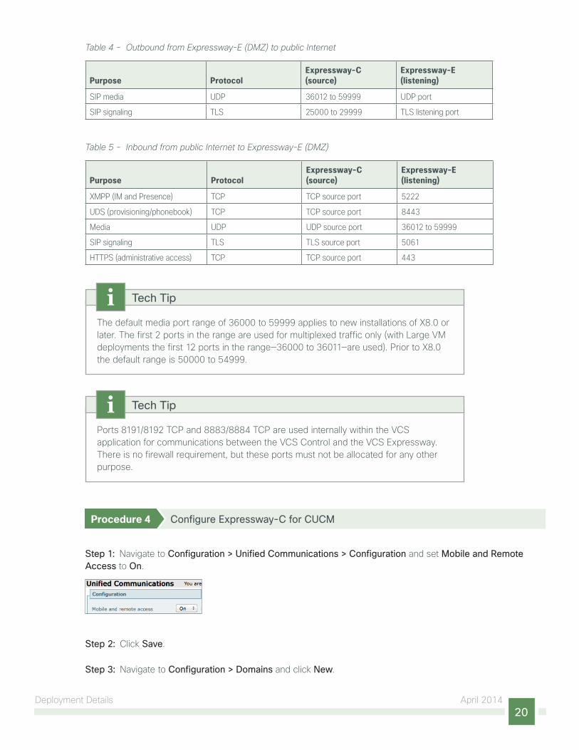
Table 4 - Outbound from Expressway-E (DMZ) to public Internet
Purpose ProtocolExpressway-C (source)
Expressway-E (listening)
SIP media UDP 36012 to 59999 UDP port
SIP signaling TLS 25000 to 29999 TLS listening port
Table 5 - Inbound from public Internet to Expressway-E (DMZ)
Purpose ProtocolExpressway-C (source)
Expressway-E (listening)
XMPP (IM and Presence) TCP TCP source port 5222
UDS (provisioning/phonebook) TCP TCP source port 8443
Media UDP UDP source port 36012 to 59999
SIP signaling TLS TLS source port 5061
HTTPS (administrative access) TCP TCP source port 443
The default media port range of 36000 to 59999 applies to new installations of X8.0 or later. The first 2 ports in the range are used for multiplexed traffic only (with Large VM deployments the first 12 ports in the range—36000 to 36011—are used). Prior to X8.0 the default range is 50000 to 54999.
Tech Tip
Ports 8191/8192 TCP and 8883/8884 TCP are used internally within the VCS application for communications between the VCS Control and the VCS Expressway. There is no firewall requirement, but these ports must not be allocated for any other purpose.
Tech Tip
Procedure 4 Configure Expressway-C for CUCM
Step 1: Navigate to Configuration > Unified Communications > Configuration and set Mobile and Remote Access to On.
Step 2: Click Save.
Step 3: Navigate to Configuration > Domains and click New.

Deployment Details April 201421
Step 4: Enter the following values in the relevant fields:
• Domain name—cisco.local
• SIP registrations and provisioning on Unified CM—On
• IM and Presence services on Unified CM—On
Step 5: Click Create Domain.
Procedure 5 Discover Unified CM and IM&P server on Expressway-C
Step 1: Navigate to Configuration > Unified Communications > Unified CM Servers, and then click New.
Step 2: Enter the following values in the relevant fields:
• Unified CM publisher address—CUCM-Pub.cisco.local
• Username—CUCMAdmin
• Password—[Password]
• TLS verify mode—Off
Step 3: Click Add Address.
Next, you configure the IM&P server for remote access.
Step 4: Navigate to Configuration > Unified Communications > IM and Presence servers, and then click New.

Deployment Details April 201422
Step 5: Enter the following values in the relevant fields:
• IM and Presence publisher address—CUCM-IMP1.cisco.local
• Username—CUCMAdmin
• Password—[Password]
• TLS verify mode—Off
Step 6: Click Add Address.
For more information about IM&P, see Unified Communications Using Cisco BE 6000 Technology Design Guide.
Reader Tip
Procedure 6 Configure Expressway-E for Unified CM
Step 1: Navigate to Configuration > Unified Communications > Configuration, and then set Mobile and remote access to On.
Step 2: Click Save.

Deployment Details April 201423
Procedure 7 Configure server certificates and CA certificates
Remote and mobile clients must verify (by validating the server certificate) the identity of the Expressway-E to which they are connecting. To do this, in their list of trusted CAs, the clients must have the certificate authority that was used to sign the Expressway-E’s server certificate.
This design requires secure communications between Expressway-C and Expressway-E, as well as between Expressway-E and endpoints located outside the enterprise.
Step 1: To generate a CSR and/or to upload a server certificate to the Expressway-C/E, navigate to Maintenance > Security certificates > Server certificate and click Generate CSR.
Step 2: To upload trusted Certificate Authority (CA) certificates on to the Expressway-C/E, navigate to Maintenance > Security certificates > Trusted CA certificate.
For more information, see the Cisco Expressway Certificate Creation and Use Deployment Guide.
Reader Tip
Procedure 8 Configure traversal client zone on Expressway-C
Step 1: Navigate to Configuration > Zones > Zones and click New.

Deployment Details April 201424
Step 2: Enter the following into the relevant fields, leaving the other fields at their default values:
• Under Configuration:
ƕ Name—TraversalClient (MRA)
ƕ Type—Traversal Client
• Under Connection credentials:
ƕ Username—admin
ƕ Password—[password]
• Under H.323:
ƕ Mode—Off
• Under SIP:
ƕ Mode—On
ƕ Port—7001
ƕ Transport—TLS
ƕ Mobile and remote access—Yes
ƕ TLS verify mode—On
ƕ Media encryption mode—Force Encrypted
ƕ ICE support—Off
ƕ Poison mode—Off
• Under Location:
ƕ Peer 1 address—EXPe1.cisco.local

Deployment Details April 201425
Step 3: Click Create zone.
Procedure 9 Configure the Expressway-C credentials on Expressway-E
Step 1: Navigate to Configuration > Authentication > Local database and click New.
Step 2: Enter the following values in the relevant fields:
• Name—admin
• Password—[password for EXPc1.cisco.local]
Deployment Details April 201426
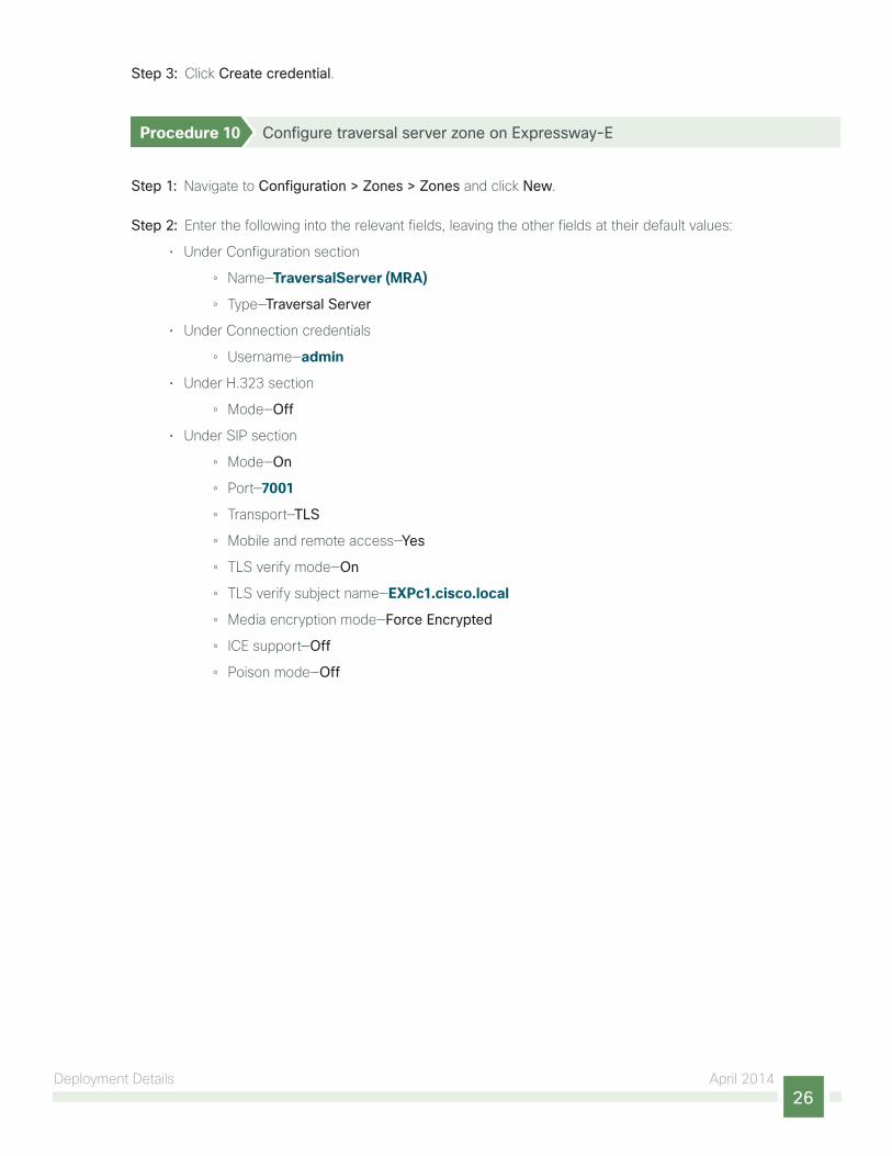
Step 3: Click Create credential.
Procedure 10 Configure traversal server zone on Expressway-E
Step 1: Navigate to Configuration > Zones > Zones and click New.
Step 2: Enter the following into the relevant fields, leaving the other fields at their default values:
• Under Configuration section
ƕ Name—TraversalServer (MRA)
ƕ Type—Traversal Server
• Under Connection credentials
ƕ Username—admin
• Under H.323 section
ƕ Mode—Off
• Under SIP section
ƕ Mode—On
ƕ Port—7001
ƕ Transport—TLS
ƕ Mobile and remote access—Yes
ƕ TLS verify mode—On
ƕ TLS verify subject name—EXPc1.cisco.local
ƕ Media encryption mode—Force Encrypted
ƕ ICE support—Off
ƕ Poison mode—Off

Deployment Details April 201427
Step 3: Click Create zone.

Deployment Details April 201428
You can configure a cluster of Expressways to provide failover (redundancy) support as well as improved scalability. For more information about setting up Expressway clusters, see Cisco Expressway cluster creation and maintenance deployment guide.
For information about configuring Jabber endpoints and DNS, see Configure DNS for Cisco Jabber.
Reader Tip
Mobile and remote access is now configured. You can now register Jabber endpoints to the CUCM without the VPN now.
Deploying B2B
1. Configure SIP profile on CUCM for Cisco Expressway-C
2. Configure SIP trunk security profile on CUCM for Cisco Expressway-C
3. Configure SIP trunk on CUCM to Expressway-C
4. Configure SIP route pattern on CUCM for B2B
5. Configure firewall
6. Configure neighbor zone on Expressway-C for CUCM
7. Configure traversal client zone on Expressway-C for Expressway-E
8. Configure search rules on Expressway-C
9. Configure transform on Expressway-C
10. Configure traversal server zone on Expressway-E for Expressway-C
11. Configure DNS zone on Expressway-E
12. Configure search rules on Expressway-E
13. Configure transform on Expressway-E
14. Configure SRV records on the public DNS server
PRO
CES
S
Procedure 1 Configure SIP profile on CUCM for Cisco Expressway-C
Step 1: Navigate to Device > Device Settings > SIP Profile, and click Add New.

Deployment Details April 201429
Step 2: Enter the following into the relevant fields, leaving the other fields at their default values:
• Name—Custom SIP Profile For Cisco Expressway-C
• Description—Custom SIP Profile For Cisco Expressway-C Server
• Enable OPTIONS Ping to monitor destination status for Trunks with Service Type “None (Default)”—Selected
• Allow Presentation Sharing using BFCP—Selected
• Allow iX Application Media—Selected
• Allow multiple codecs in answer SDP—Selected
Step 3: Click Save.
Procedure 2 Configure SIP trunk security profile on CUCM for Cisco Expressway-C
For B2B calls to be routed, you must create a SIP trunk between CUCM and Expressway-C.
In this design, the Expressway-C is already configured for mobile and remote access. Port 5060 is used for line-side registrations of endpoints in mobile and remote access scenario. A SIP trunk cannot be formed between Expressway-C and CUCM by using port 5060 because the CUCM cannot accept line-side and trunk-side communication from the same device using the same port.
Thus the SIP trunk from Expressway-C to CUCM has to use another SIP port on the CUCM incoming side. This design uses 5560 as the SIP trunk incoming port. You can change the SIP incoming port by creating a new SIP trunk security profile and assigning this profile to the SIP trunk created between CUCM and Expressway-C.
Step 1: Navigate to System > Security > SIP Trunk Security Profile and click Add New.

Deployment Details April 201430
Step 2: Enter the following values in the relevant fields:
• Name—Non Secure SIP Trunk Profile port 5560
• Description—SIP Profile with listening port 5560
• Incoming Port—5560
• Accept presence subscription—Selected
• Accept out-of-dialog refer—Selected
• Accept unsolicited notification—Selected
• Accept replaces header—Selected
Step 3: Click Save.
Procedure 3 Configure SIP trunk on CUCM to Expressway-C
Step 1: Navigate to Device > Trunk and click Add New.

Deployment Details April 201431
Step 2: Enter the following into the relevant fields:
• Trunk Type—SIP Trunk
• Device Protocol—SIP
• Trunk Service Type—None(Default)
Step 3: Click Next.
Step 4: Enter the following into the relevant fields. Leave the other fields at their default values.
• Device Name—SIP_Trunk_ExpC
• Description—SIP_Trunk_ExpC for B2B Calls
• Device Pool—Video_DP
• Calling and Connected Party Info Format—Deliver URI only in connected party, if available
• Destination Address—192.168.1.29
• SIP Trunk Security Profile—Non Secure SIP Trunk Profile port 5560
• SIP Profile—Custom SIP Profile for Cisco Expressway-C
• DTMF Signaling Method—RFC 2833
• Normalization Script—vcs-interop

Deployment Details April 201432
Step 5: Click Save.
Procedure 4 Configure SIP route pattern on CUCM for B2B
The following SIP route pattern is configured to route all B2B calls towards the Expressway-C, which doesn’t match any existing route patterns.
Step 1: Navigate to Call Routing > SIP Route Pattern and click Add New.
Step 2: Enter the following into the relevant fields, leaving the other fields at their default values:
• Pattern Usage—Domain Routing
• IPv4 Pattern—*
• SIP Trunk/Route List—SIP_Trunk_ExpC
Step 3: Click Save.

Deployment Details April 201433
Procedure 5 Configure firewall
The firewall must be configured to allow traffic on following ports between your inside network (where the Expressway-C is located) and the DMZ (where the Expressway-E is located) and between the DMZ and the public Internet.
Table 6 - Outbound from Expressway-C (inside) to Expressway-E (DMZ)
Purpose Transport Protocol Source Port Destination Port
Management TCP >=1024 80 / 443 / 22 / 23
SNMP Monitoring UDP >=1024 161
RTP Assent UDP 36002 to 59999 36000
RTCP Assent UDP 36002 to 59999 36001
SIP TCP/TLS TCP 25000 to 29999 7011
H.323 RAS Assent UDP 1719 6011
Q.931/H.225 and H.245 TCP 15000 to 19999 2776
The first 2 ports in the media port range of 36000 to 59999 are used for only for multiplexed traffic (with Large VM deployments, the first 12 ports in the range of 36000 to 36011 are used).
Tech Tip
Table 7 - Outbound from Expressway-E (DMZ) to Expressway-C (inside)
Purpose Transport Protocol Source Port Destination Port
Logging UDP 30000 to 35999 514
Management TCP >=1024 80 / 443
LDAP (for log in, if required) TCP 30000 to 35999 389 / 636
NTP (time sync) UDP 123 123
DNS UDP >=1024 53
Table 8 - Outbound from Expressway-E (DMZ) to public Internet
Purpose Transport Protocol Source Port Destination Port
SIP TCP & TLS TCP 25000 to 29999 >=1024
SIP UDP UDP 5060 >=1024
RTP & RTCP UDP 36000 to 59999 >=1024
DNS UDP >=1024 53
NTP (Time Sync) UDP 123 123
Deployment Details April 201434
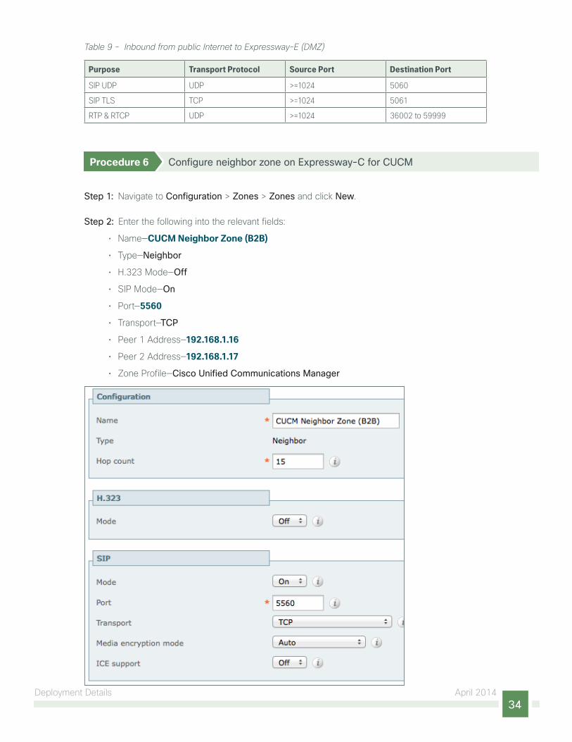
Table 9 - Inbound from public Internet to Expressway-E (DMZ)
Purpose Transport Protocol Source Port Destination Port
SIP UDP UDP >=1024 5060
SIP TLS TCP >=1024 5061
RTP & RTCP UDP >=1024 36002 to 59999
Procedure 6 Configure neighbor zone on Expressway-C for CUCM
Step 1: Navigate to Configuration > Zones > Zones and click New.
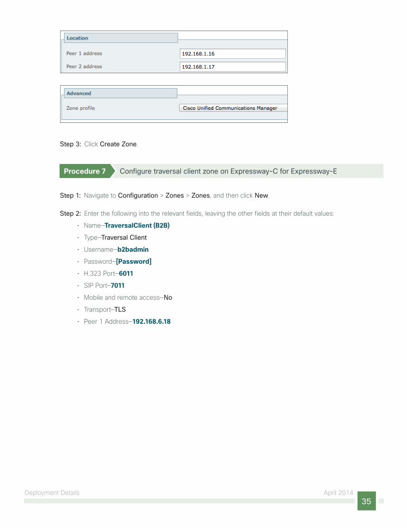
Step 2: Enter the following into the relevant fields:
• Name—CUCM Neighbor Zone (B2B)
• Type—Neighbor
• H.323 Mode—Off
• SIP Mode—On
• Port—5560
• Transport—TCP
• Peer 1 Address—192.168.1.16
• Peer 2 Address—192.168.1.17
• Zone Profile—Cisco Unified Communications Manager
Deployment Details April 201435
Step 3: Click Create Zone.
Procedure 7 Configure traversal client zone on Expressway-C for Expressway-E
Step 1: Navigate to Configuration > Zones > Zones, and then click New.
Step 2: Enter the following into the relevant fields, leaving the other fields at their default values:
• Name—TraversalClient (B2B)
• Type—Traversal Client
• Username—b2badmin
• Password—[Password]
• H.323 Port—6011
• SIP Port—7011
• Mobile and remote access—No
• Transport—TLS
• Peer 1 Address—192.168.6.18

Deployment Details April 201436

Deployment Details April 201437
Step 3: Click Create Zone.
Procedure 8 Configure search rules on Expressway-C
Step 1: Navigate to Configuration > Dial Plan > Search Rules, and click New.
Step 2: Enter the following into the relevant fields, leaving the other fields at their default values:
• Rule Name—B2B-to-cisco.com
• Description—B2B calls to cisco.com
• Priority—101
• Mode—Alias Pattern Match
• Pattern type—Regex
• Pattern String—(?!.*@%localdomains%.*$)(.*)
• Pattern Behavior—Leave
• On Successful Match—Stop
• Target—TraversalClient (B2B)
• State—Enabled
Step 3: Click Create Search Rule.
Step 4: Click New.

Deployment Details April 201438
Step 5: Enter the following into the relevant fields, leaving other fields at their default values:
• Rule Name—B2B-to-cisco.local
• Description—B2B calls to cisco.local
• Priority—100
• Mode—Alias Pattern Match
• Pattern type—Regex
• Pattern String—(.*)(@cisco.local).*
• Pattern Behavior—Replace
• Replace String—\1\2
• On Successful Match—Stop
• Target—CUCM Neighbor Zone (B2B)
• State—Enabled
Step 6: Click Create Search Rule.
Procedure 9 Configure transform on Expressway-C
Step 1: Navigate to Configuration > Dial Plan > Transforms and click New.
Deployment Details April 201439
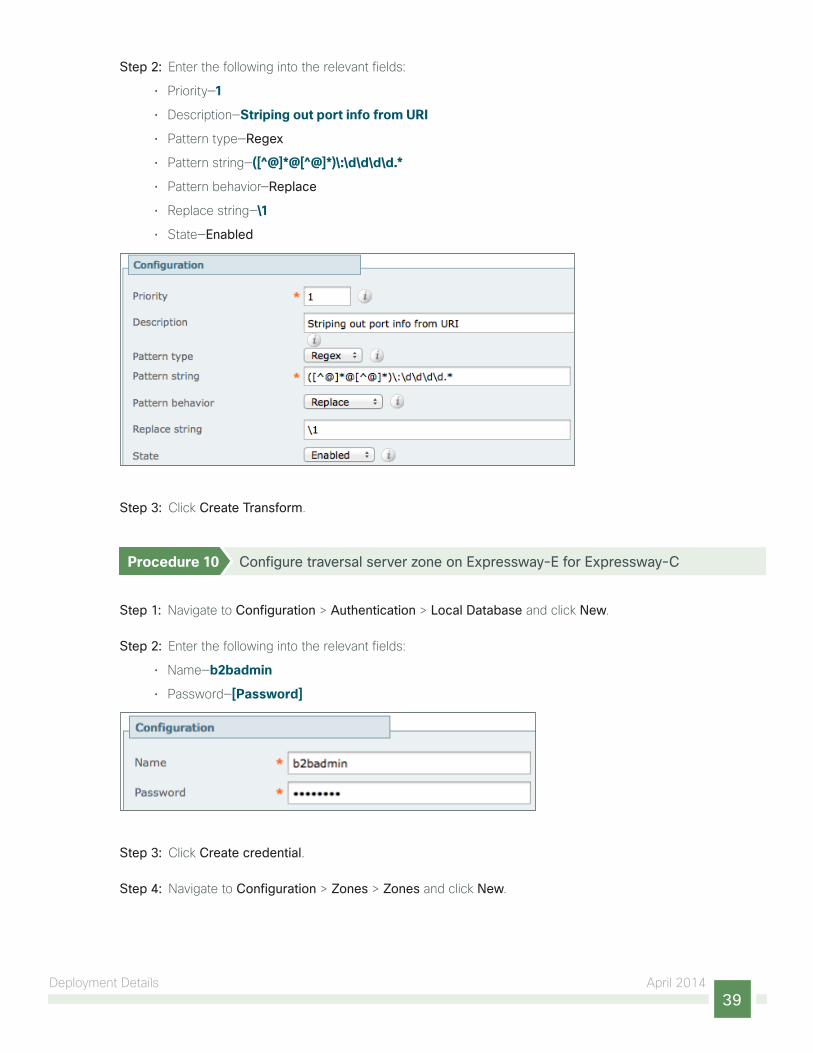
Step 2: Enter the following into the relevant fields:
• Priority—1
• Description—Striping out port info from URI
• Pattern type—Regex
• Pattern string—([^@]*@[^@]*)\:\d\d\d\d.*
• Pattern behavior—Replace
• Replace string—\1
• State—Enabled
Step 3: Click Create Transform.
Procedure 10 Configure traversal server zone on Expressway-E for Expressway-C
Step 1: Navigate to Configuration > Authentication > Local Database and click New.
Step 2: Enter the following into the relevant fields:
• Name—b2badmin
• Password—[Password]
Step 3: Click Create credential.
Step 4: Navigate to Configuration > Zones > Zones and click New.
Deployment Details April 201440
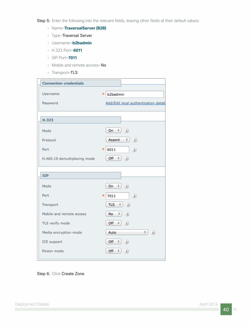
Step 5: Enter the following into the relevant fields, leaving other fields at their default values:
• Name—TraversalServer (B2B)
• Type—Traversal Server
• Username—b2badmin
• H.323 Port—6011
• SIP Port—7011
• Mobile and remote access—No
• Transport—TLS
Step 6: Click Create Zone.

Deployment Details April 201441
Procedure 11 Configure DNS zone on Expressway-E
For a B2B call, the Expressway-E doesn’t know where to route a call for a different domain; it doesn’t have a neighbor created for that domain. Thus it routes all the call via the public DNS server.
Step 1: Navigate to Configuration > Zones > Zones and click New.
Step 2: Enter the following into the relevant fields, leaving other fields at their default values:
• Name—DNS Zone (B2B)
• Type—DNS
• H.323 Mode—On
• SIP Mode—On
• Fallback Transport Protocol—TCP
Step 3: Click Create Zone.
Procedure 12 Configure search rules on Expressway-E
Step 1: Navigate to Configuration > Dial Plan > Search Rules, and click New.

Deployment Details April 201442
Step 2: Enter the following into the relevant fields, leaving other fields at their default values:
• Rule Name—B2B-to-cisco.com
• Description—B2B calls to cisco.com
• Priority—101
• Mode—Alias Pattern Match
• Pattern type—Regex
• Pattern String—(?!.*@%localdomains%.*$)(.*)
• Pattern Behavior—Leave
• On Successful Match—Stop
• Target—DNS Zone (B2B)
• State—Enabled
Step 3: Click Create Search Rule.
Step 4: Click New.

Deployment Details April 201443
Step 5: Enter the following into the relevant fields, leaving other fields at their default values:
• Rule Name—B2B-to-cisco.local
• Description—B2B calls to cisco.local
• Priority—100
• Mode—Alias Pattern Match
• Pattern type—Regex
• Pattern String—(.*)(@cisco.local).*
• Pattern Behavior—Replace
• Replace String—\1\2
• On Successful Match—Stop
• Target—TraversalServer (B2B)
• State—Enabled
Step 6: Click Create Search Rule.

Deployment Details April 201444
Procedure 13 Configure transform on Expressway-E
Step 1: Navigate to Configuration > Dial Plan > Transforms and click New.
Step 2: Enter the following into the relevant fields:
• Priority—1
• Description—Striping out port info from URI
• Pattern type—Regex
• Pattern string—([^@]*@[^@]*)\:\d\d\d\d.*
• Pattern behavior—Replace
• Replace string—\1
• State—Enabled
Step 3: Click Create Transform.
Procedure 14 Configure SRV records on the public DNS server
Ensure that the public DNS server have the following SRV and A records so that the endpoints can discover the Expressway-E to route business-to-business calls.
_sip._tcp.cisco.local. SRV 10 10 5060 expe1.cisco.local
_sip._udp.cisco.local. SRV 10 10 5060 expe1.cisco.local
expe1.cisco.local. IN A 192.168.6.18

Appendix A: Product List April 201445
Appendix A: Product ListComponent Product Description Part Number Software
Call Control Cisco Business Edition 6000 with up to 1000 users BE6K-SW-10.0 10.0
Cisco Collaboration Edge Cisco Expressway-C EXPWY-VE-C-K9 s42700x8_1_0
Cisco Expressway-E EXPWY-VE-E-K9
Soft Client Cisco Jabber for Windows JAB9-DSK-K9 9.6 (Experimental)
Cisco Jabber for IOS 9.6

Americas HeadquartersCisco Systems, Inc.San Jose, CA
Asia Pacific HeadquartersCisco Systems (USA) Pte. Ltd.Singapore
Europe HeadquartersCisco Systems International BV Amsterdam,The Netherlands
Cisco has more than 200 offices worldwide. Addresses, phone numbers, and fax numbers are listed on the Cisco Website at www.cisco.com/go/offices.
ALL DESIGNS, SPECIFICATIONS, STATEMENTS, INFORMATION, AND RECOMMENDATIONS (COLLECTIVELY, “DESIGNS”) IN THIS MANUAL ARE PRESENTED “AS IS,” WITH ALL FAULTS. CISCO AND ITS SUPPLIERS DISCLAIM ALL WARRANTIES, INCLUDING, WITHOUT LIMITATION, THE WARRANTY OF MERCHANTABILITY, FITNESS FOR A PARTICULAR PURPOSE AND NONINFRINGEMENT OR ARISING FROM A COURSE OF DEALING, USAGE, OR TRADE PRACTICE. IN NO EVENT SHALL CISCO OR ITS SUPPLIERS BE LIABLE FOR ANY INDIRECT, SPECIAL, CONSEQUENTIAL, OR INCIDENTAL DAMAGES, INCLUDING, WITHOUT LIMITATION, LOST PROFITS OR LOSS OR DAMAGE TO DATA ARISING OUT OF THE USE OR INABILITY TO USE THE DESIGNS, EVEN IF CISCO OR ITS SUPPLIERS HAVE BEEN ADVISED OF THE POSSIBILITY OF SUCH DAMAGES. THE DESIGNS ARE SUBJECT TO CHANGE WITHOUT NOTICE. USERS ARE SOLELY RESPONSIBLE FOR THEIR APPLICATION OF THE DESIGNS. THE DESIGNS DO NOT CONSTITUTE THE TECHNICAL OR OTHER PROFESSIONAL ADVICE OF CISCO, ITS SUPPLIERS OR PARTNERS. USERS SHOULD CONSULT THEIR OWN TECHNICAL ADVISORS BEFORE IMPLEMENTING THE DESIGNS. RESULTS MAY VARY DEPENDING ON FACTORS NOT TESTED BY CISCO.
Any Internet Protocol (IP) addresses used in this document are not intended to be actual addresses. Any examples, command display output, and figures included in the document are shown for illustrative purposes only. Any use of actual IP addresses in illustrative content is unintentional and coincidental.
© 2013 Cisco Systems, Inc. All rights reserved.
Cisco and the Cisco logo are trademarks or registered trademarks of Cisco and/or its affiliates in the U.S. and other countries. To view a list of Cisco trademarks, go to this URL: www.cisco.com/go/trademarks. Third-party trademarks mentioned are the property of their respective owners. The use of the word partner does not imply a partnership relationship between Cisco and any other company. (1110R)
Please use the feedback form to send comments and suggestions about this guide.
Feedback
B-470-COL-1 04/14