code shift - ieee power & energy...
TRANSCRIPT

72 ieee power & energy magazine november/december 20131540-7977/13/$31.00©2013IEEE
Digital Object Identifier 10.1109/MPE.2013.2278002
Date of publication: 18 October 2013 IMAGE LICENSED BY INGRAM PUBLISHING
GGRID CODES (GCs) AND DYNAMIC WIND turbine (WT) models are key tools to allow increasing renewable energy penetration with-out challenging security of supply. In this article, the state of the art and the further devel-opment of both tools are discussed, focusing on the European and North American experiences.
GC Development: Lessons Learned GCs have to be prepared for conditions years and decades ahead in order to require the appro-priate technical features of new generation equipment in the context of the power system challenges that will follow future development in the grid. Twenty years ago, most GCs did not anticipate much change in the future power system structure. The development of signifi -cant renewable penetration levels was simply not part of the future scenarios. Today, it is still challenging to estimate credible future energy scenarios. In particular, it is diffi cult to estimate the growth of renewable energy (RE) genera-tion. In the last decade, grid code requirements under estimated the rapid growth of distributed RE in continental Europe. This resulted in cer-tain technical issues that within the space of a few years have moved from insignifi cance to major system concerns. Two issues in particular underline this point: fault ride-through (FRT) capability and problems related to a narrow
Code ShiftCode ShiftCode ShiftGrid Specifications and Dynamic Wind Turbine Models
november/december 2013 ieee power & energy magazine 73
By Thomas Ackermann, Abraham Ellis, Jens Fortmann, Julia Matevosyan, Ed Muljadi, Richard Piwko, Pouyan Pourbeik, Eckard Quitmann, Poul Sorensen, Helge Urdal, and Bob Zavadil
frequency operating range (such as the “50.2-Hz issue”). We discuss these below.
The need for FRT capability is nowadays widely described by various studies as well as practical records of faults with large loss of dis-tributed generation. Previously, when large central synchronous generation provided nearly all the generation capacity, the philosophy of allowing or even requiring small distributed generators to disconnect during disturbances until the system recovered appeared appropriate. This approach was suitable when the instantaneous penetration of such new generation types covered only a few percent of the demand but not in power systems with significant levels of RE generation.
A similar case is the permission (or often the system operator requirement) to trip distributed generation during severe system disturbances involving over frequencies. Traditionally, distrib-uted and RE generation devices were built with a narrow tolerance for frequency deviations. This may be noncritical for low instantaneous RE pen-etration levels but can become critical when pen-etration becomes significant. In fact, it has led to a large problem with tens of gigawatts of RE in Germany set to trip at 50.2 Hz.
After the FRT and 50.2-Hz problems were iden-tified, incentive programs were started in several European countries (Germany, Italy, Portugal, and Spain) to trigger retrofits of already installed WTs and PV systems. Retrofitting has been shown to be costly, however, and is often problematic from a legal and technical point of view as well.
Countries in which the growth of RE started later benefited from the experience of others.

74 ieee power & energy magazine november/december 2013
Requirements regarding FRT or minimum frequency range are being implemented all over the world, even though the specific penetration with RE is still very low. This anticipa-tion of technical needs for system development is reason-able in light of the fact that some countries have seen up to a ten fold increase in installed capacity in a single year, as it occurred with PV capacity in Italy and Great Britain in 2011. In the United States, the discussion about an update of the IEEE 1547 standard in order to appropriately address the FRT and frequency range issues has just started.
GCs Around the WorldIn what follows, the North American as well as the European status of GC development is presented.
North AmericaThe North American Electric Reliability Corporation (NERC) has primary responsibility for maintaining the reliability of the power grid. Recognizing that existing reli-ability rules did not adequately set clear requirements for new wind and solar technologies, NERC commissioned the Integration of Variable Generation Task Force (IVGTF) to:
✔ identify short comings in existing reliability standards ✔ make recommendations on what revisions should be implemented.
In September 2012, the IVGTF published a special assess-ment report, Interconnection Requirements for Variable Gen-eration. The report contains specific recommendations for:
✔ reactive power and voltage control ✔ performance during and after disturbances
✔ active power control ✔ harmonics and subsynchronous interaction ✔ models for facility interconnection studies ✔ communications between wind and solar plants and grid operators.
NERC is currently using these recommendations to cre-ate and/or revise a series of high-priority reliability standards related to what it calls “generator verification,” including:
✔ PRC-019, Coordination of Generator Voltage Regula-tor Controls with Unit Capabilities and Protection
✔ PRC-024, Generator Performance During Frequency and Voltage Excursions
✔ MOD-024/025, Verification of Generator Gross and Net Real/Reactive Power Capability
✔ MOD-026, Verification of Models and Data for Gen-erator Excitation System Functions
✔ MOD-027, Verification of Generator Unit Frequency Response.
NERC and IEEE are also working together to address another reliability issue: the IEEE 1547 requirement for dis-tribution-connected generation to trip off when voltage and frequency excursions occur. As the penetration of roof top PV increases, IEEE 1547–compliant PV systems increase the severity of loss-of-generation events. For example, a transmis-sion system fault that causes the loss of a thermal generating plant could simultaneously initiate the tripping of roof top PV systems due to the momentary dip in voltage during the fault. The IVGTF is making recommendations to resolve this situation (Task 1-7). The IVGTF 1-7 report is recommending that IEEE 1547 be revised to include an explicit FRT require-
ment that does not conflict with the “must trip” envelope contained in the current standard.
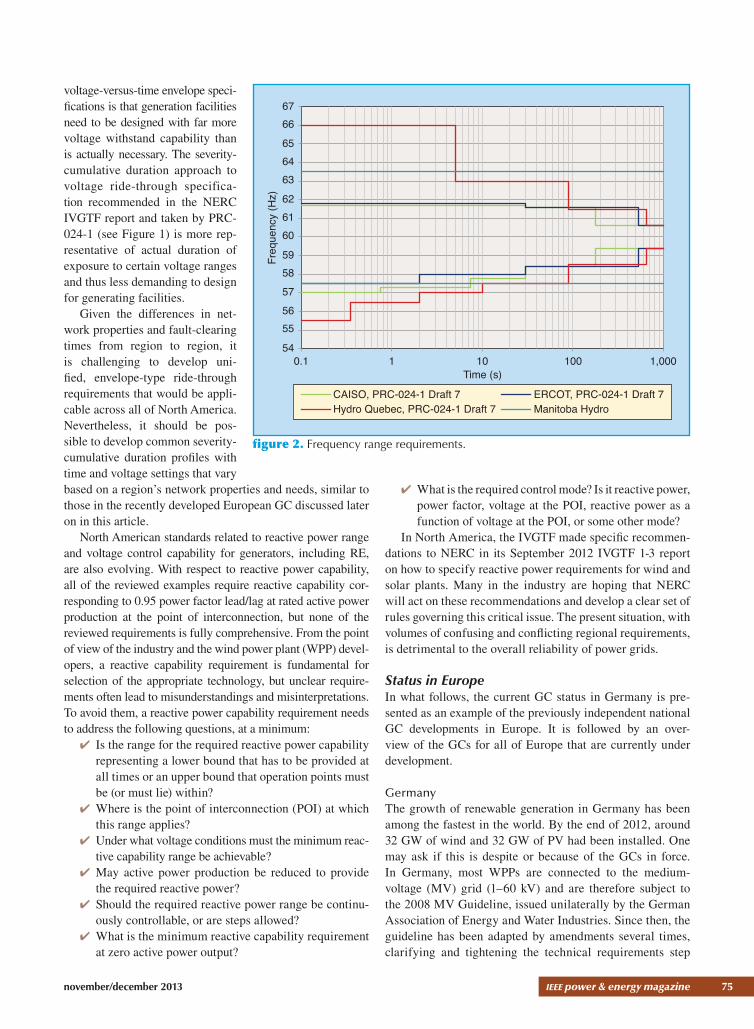
In the absence of the updated and revised NERC standards, some ISOs and utilities facing rapid growth of renewable generation in their jurisdictions have developed their own interconnection require-ments. Figures 1 and 2 illustrate examples of requirements at the point of interconnection (POI) for low- and high-voltage ride-through and frequency range capabilities. For comparison, the requirements currently stated in NERC’s PRC-024-1, Generator Frequency and Voltage Protective Relay Settings (Draft 7), which applies to large generators, are also plotted.
As in Europe, voltage ride-through and frequency range re-quirements in North America vary widely from region to region. The adverse consequence of varying
2.01.91.81.71.61.51.41.31.21.11.0
Volta
ge a
t PO
I (p.
u.)
0.90.80.70.60.50.40.30.20.10.0
00.2
50.5
00.7
51.0
01.2
5
Time (s)1.5
01.7
52.0
02.2
52.5
02.7
53.0
03.2
53.5
03.7
54.0
0
ERCOTCAISO, PRC-024-1 Draft 7Manitoba Hydro, 230 kVManitoba Hydro, 230 kV, ReducedGeneration Output Is PermittedHydro Quebec
figure 1. Low and high fault ride-through. The requirements in PRC-024-1 are severity-cumulative duration curves, while other requirements are voltage-versus-time envelopes.
november/december 2013 ieee power & energy magazine 75
voltage-versus-time envelope speci-fications is that generation facilities need to be designed with far more voltage withstand capability than is actually necessary. The severity-cumulative duration approach to voltage ride-through specifica-tion recommended in the NERC IVGTF report and taken by PRC-024-1 (see Figure 1) is more rep-resentative of actual duration of exposure to certain voltage ranges and thus less demanding to design for generating facilities.
Given the differences in net-work properties and fault-clearing times from region to region, it is challenging to develop uni-fied, envelope-type ride-through requirements that would be appli-cable across all of North America. Nevertheless, it should be pos-sible to develop common severity-cumulative duration profiles with time and voltage settings that vary based on a region’s network properties and needs, similar to those in the recently developed European GC discussed later on in this article.
North American standards related to reactive power range and voltage control capability for generators, including RE, are also evolving. With respect to reactive power capability, all of the reviewed examples require reactive capability cor-responding to 0.95 power factor lead/lag at rated active power production at the point of interconnection, but none of the reviewed requirements is fully comprehensive. From the point of view of the industry and the wind power plant (WPP) devel-opers, a reactive capability requirement is fundamental for selection of the appropriate technology, but unclear require-ments often lead to misunderstandings and misinterpretations. To avoid them, a reactive power capability requirement needs to address the following questions, at a minimum:
✔ Is the range for the required reactive power capability representing a lower bound that has to be provided at all times or an upper bound that operation points must be (or must lie) within?
✔ Where is the point of interconnection (POI) at which this range applies?
✔ Under what voltage conditions must the minimum reac-tive capability range be achievable?
✔ May active power production be reduced to provide the required reactive power?
✔ Should the required reactive power range be continu-ously controllable, or are steps allowed?
✔ What is the minimum reactive capability requirement at zero active power output?
✔ What is the required control mode? Is it reactive power, power factor, voltage at the POI, reactive power as a function of voltage at the POI, or some other mode?
In North America, the IVGTF made specific recommen-dations to NERC in its September 2012 IVGTF 1-3 report on how to specify reactive power requirements for wind and solar plants. Many in the industry are hoping that NERC will act on these recommendations and develop a clear set of rules governing this critical issue. The present situation, with volumes of confusing and conflicting regional requirements, is detrimental to the overall reliability of power grids.
Status in EuropeIn what follows, the current GC status in Germany is pre-sented as an example of the previously independent national GC developments in Europe. It is followed by an over-view of the GCs for all of Europe that are currently under development.
GermanyThe growth of renewable generation in Germany has been among the fastest in the world. By the end of 2012, around 32 GW of wind and 32 GW of PV had been installed. One may ask if this is despite or because of the GCs in force. In Germany, most WPPs are connected to the medium-voltage (MV) grid (1–60 kV) and are therefore subject to the 2008 MV Guideline, issued unilaterally by the German Association of Energy and Water Industries. Since then, the guideline has been adapted by amendments several times, clarifying and tightening the technical requirements step
6766
656463
626160
59Freq
uenc
y (H
z)58575655
540.1 1 10
Time (s)100 1,000
CAISO, PRC-024-1 Draft 7Hydro Quebec, PRC-024-1 Draft 7 Manitoba Hydro
ERCOT, PRC-024-1 Draft 7
figure 2. Frequency range requirements.
76 ieee power & energy magazine november/december 2013
by step. In the spring of 2013, the Association for Electric, Electronic, and Information Technologies (VDE) began to transform the guideline into a VDE Forum for Network Technology and Network Operation (FNN) recommenda-tion. This process is expected to take one to two years but has the great advantage of having reasonable stakeholder involvement.
The 2007 Transmission Code established technical high-voltage (HV) requirements. Meanwhile, WPP connections to the 220-kV level and above are still rare in Germany. WPPs connected to the 110-kV level have been increasing over the last several years, however. Since 2008, a VDE FNN group of
experts from the system operators, industry, and other parties has been working on a new VDE recommenda-tion, VDE-AR-N 4120 (draft), specifically for the 110-kV level. This new recommendation includes certain new technical aspects. For the first time, for example, explicit numbers are provided regarding negative sequence fault current contribution during unbalanced grid faults.
In addition to purely technical requirements, Ger-many has also established a complex certification pro-
cess, applicable to the individual generating unit type as well as to the WPP. Its level of detail and explicit requirement to involve independent, accredited certifying bodies is com-plex and time-consuming.
Beyond these technical and certification rules, all Ger-man WPPs must meet the requirements of the Ordinance on System Services by Wind Energy Plants (SDLWindV), issued by the German federal government in 2009. The SDL-WindV sought to incentivize the better integration of WPPs into the electrical system, in particular the upgrade of older WTs to fault ride-through capability and the installation of technical communication means for emergency dispatching
by the system operator. Currently, all connecting WPPs must meet these requirements. The technical requirements of the SDLWindV remain binding; the financial incentive to retrofit the WPPs is fading out, however.
ENTSO-E Requirements for Generators Network Code for EuropeThe European Commission (EC) has initiated development of nine Europe-wide GCs or “network codes” (NCs), as they are called. As of the spring of 2013, the first three NCs are in the final phase of becoming legally binding for all of Europe, the first possibly by the first half of 2014. The out-come will depend on decisions to be made by energy ministry representatives from the 27 Euro-pean Union (EU) countries in a process called comitology. The most relevant NC for renewables, the Requirements for Generators (RfG), is discussed briefly below.
The RfG NC was used as the pilot to test and refine the NC code development process by ENTSO-E (the organization of 41 European TSOs, which covers 34
RG Continental Europe
IS
IE GB
FR
ESPT
MADZ
TN
GR TR
CY
BGMK
AL
RS
RO
ME
BA
IT
HRSIAT HU
SKUA
MD
BY
RU
LTRU
LV
EE
FI
SENO
DK
DECZ
PL
CH
LUBE
NL
RG NordicRG BalticRG UKRG Ireland
figure 3. An overview of the European synchronous areas.
table 1. Thresholds for type B, C, and D PGMs.
PGM Maximum Capacity Thresholds
Synchronous Area Type B Type C Type DContinental Europe 1 MW 50 MW 75 MWNordic 1.5 MW 10 MW 30 MWGreat Britain 1 MW 10 MW 30 MWIreland 0.1 MW 5 MW 10 MWBaltic 0.5 MW 10 MW 15 MW

november/december 2013 ieee power & energy magazine 77
countries). The RfG covers a wide range of connection requirements (54 groups of capabilities). Some of these connection requirements are mandatory and exhaustive, e.g., frequency range, and some are non-mandatory and nonexhaustive (deci-sions deferred to the national level).
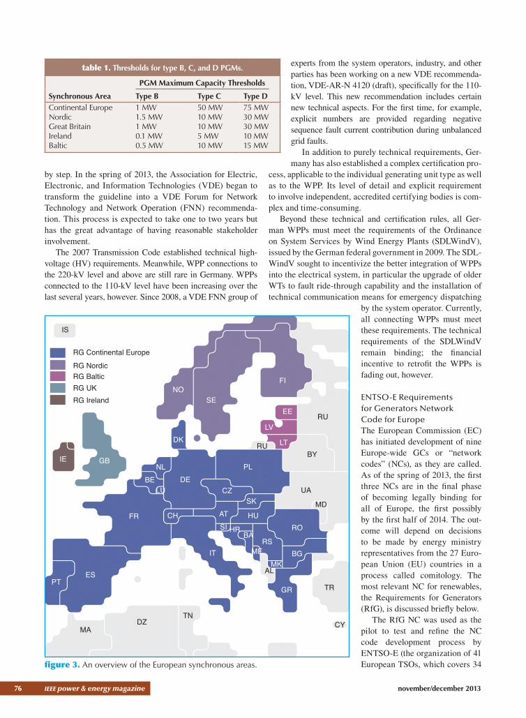
Requirements for power-generating modules (PGMs) are brought in on a graded basis, with increasing significance as connec-tion requirements increase. The PGMs are split into four types, with Type A, starting at 800 W, as the least significant. The thresh-olds for Types B, C, and D are given in Table 1 for each of the synchronous European areas. An overview of these areas is given in Figure 3.
All PGMs with connection points at 110 kV or higher are automatically classified as Type D, regardless of MW size. Some of the requirements covered by RfG are discussed below.
✔ Fault ride-through voltage against time: The typical focus on the voltage-against-time curve as the key aspect describing the FRT requirements is applied with caution in the RfG, as differences in ini-tial prefault conditions can make the seemingly easi-est requirements (140 ms) just as challenging as the most onerous requirement (250 ms). Another major factor is where the reference point is for the voltage-against-time curve. In Europe this is always defined as the connection point, in North America typically as POI, which can be 400 kV for a very large WPP or the generator terminals for a single WT, at 690 V. Each TSO is required to define and make publicly available the pre- and post fault conditions applying in its jurisdiction following stakeholder consultation and National Regulatory Authority input. The val-ues of the voltages and times in Figure 4 are deter-mined at the national level within sets of permitted values tabulated in the RfG for the different PGM types. This illustrates the clear intent of having ride-through capability for faults at the transmission level (with wide spread impact) including impact on distri-bution-connected WPPs, without covering require-ments for faults at the distribution level (with only limited local impact). The requirement for asymmet-ric faults as well as active power recovery will be decided at the national level.
✔ Reactive capability and voltage control: The steady-state reactive power capability at the connection point is also provided in tables in the RfG. The steady-state voltage ranges in which these levels of reactive power have to be available vary according to synchronous
area between 0.10 p.u. and 0.225 p.u. Reactive power requirements below maximum capacity are defined on a national basis and may include conditions for reactive power at zero active power. The power park module shall according to Article 16 also be capable of providing reactive power automatically by either voltage control mode, reactive power control mode, or power factor control mode.
Future ChallengesFurther system needs can be expected to become relevant, particularly with the increase of non synchronous genera-tion. This will result in a wide range of power system ser-vices previously provided by synchronous generators that will steadily migrate across to RES generation. The addi-tional services to be offered by renewable generation and other generation may include:
✔ inertia and/or fast primary response as well as syn-chronizing torque
✔ mitigation of negative sequence voltages ✔ damping of low-order harmonics and active filtering ✔ development of the protection system to deal with future lower short-circuit currents
✔ resynchronization and blackstart capability.
Dynamic Models for WT GeneratorsOne of the key challenges with renewable generation technol-ogies has been developing and maintaining standard public computer simulation models for the purpose of power system studies. In 2007, the International Council on Large Electric Systems (CIGRE) published a report on the subject of the dynamic performance of wind generation technologies and presented some initial ideas about potential simplified model structures. Shortly after the inception of the CIGRE group, the Western Electricity Coordinating Council (WECC) initiated a task force to develop actual generic models and implement
0 tclear trec1 trec2 trec3
Urec1
Uclear
Uret
1.0
Urec2
t /s
U/p.u.
figure 4. An FRT profile of a PGM according to ENTSO-E’s RfG NC.
78 ieee power & energy magazine november/december 2013
them for the commercial tools used in the western U.S. sys-tem. The efforts of this task force, the WECC Wind Generator Modeling Group, culminated in the development of the first generation of generic models for WT generators (WTGs) and their implementation in several commercial simulation soft-ware packages. These models were released around 2009. In late 2009, the International Electrotechnical Commission (IEC) started a working group (IEC TC88 WG27) to define standard WTG models. At about the same time, the WECC task force changed its name and became the Renewable Energy Modeling Task Force (REMTF) and was chartered with updating the wind generation generic models as well as developing generic models for PV generation. During these years, the IEEE Power System Dynamic Performance Com-mittee’s Working Group on Dynamic Performance of Wind Generation has also served as a forum for these discussions. This and other groups have participated in panel sessions and tutorials to foster collaboration and the exchange of ideas. Finally, a NERC special report issued in 2010, Standard Models for Variable Generation, highlighted the need for such standard generic models in North America. Over the past three years, some significant progress has been made by the WECC and IEC modeling groups.
Deficiencies were identified in the initial generation of the generic WTG models in 2010. This led both the WECC and IEC groups to focus on expanding the first-generation models to attempt to cover a wider range of control strategies. Any modeling effort is an evolving
process, especially in the case of renewable technologies such as WTGs, where the technology has been constantly changing and evolving in parallel with the modeling efforts. These so-called deficiencies in the first genera-tion of models were therefore to be expected.
The remainder of this article is focused on generic and public models. There are, of course, vendor-specific models that provide greater fidelity available from the equipment vendors, but in many cases these are shared only under non disclosure agreements. It is outside the scope of this article to go into the details of why there is a need for a hierarchy of models. For such a discussion, the reader is encouraged to consult references such as the NERC special report.
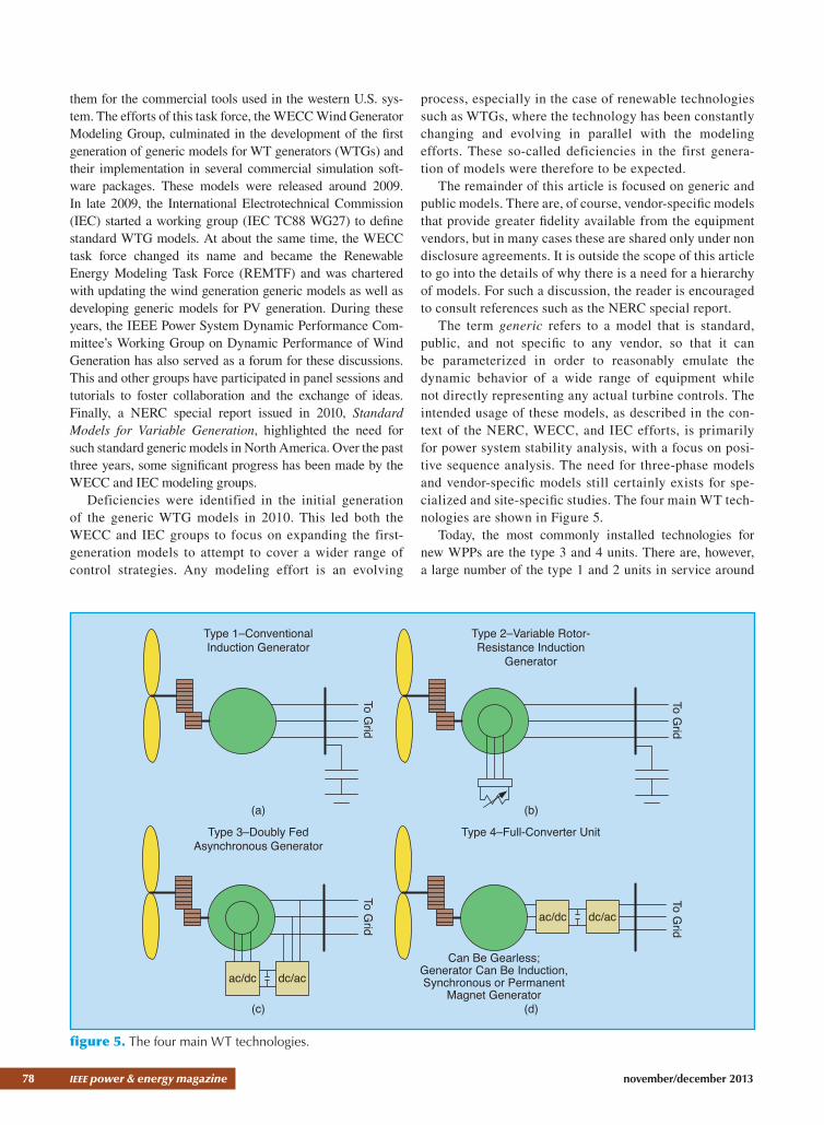
The term generic refers to a model that is standard, public, and not specific to any vendor, so that it can be parameterized in order to reasonably emulate the dynamic behavior of a wide range of equipment while not directly representing any actual turbine controls. The intended usage of these models, as described in the con-text of the NERC, WECC, and IEC efforts, is primarily for power system stability analysis, with a focus on posi-tive sequence analysis. The need for three-phase models and vendor-specific models still certainly exists for spe-cialized and site-specific studies. The four main WT tech-nologies are shown in Figure 5.
Today, the most commonly installed technologies for new WPPs are the type 3 and 4 units. There are, however, a large number of the type 1 and 2 units in service around
Type 1–ConventionalInduction Generator
Type 2–Variable Rotor-Resistance Induction
Generator
Type 4–Full-Converter Unit
To Grid
To Grid
Type 3–Doubly FedAsynchronous Generator
To Grid
ac/dc dc/ac
To Grid
ac/dc dc/ac
Can Be Gearless;Generator Can Be Induction,Synchronous or Permanent
Magnet Generator
(a) (b)
(c) (d)
figure 5. The four main WT technologies.
november/december 2013 ieee power & energy magazine 79
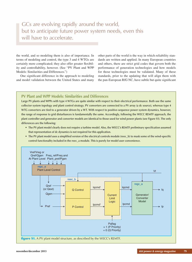
the world, and so modeling them is also of importance. In terms of modeling and control, the type 3 and 4 WTGs are certainly more complicated; they also offer greater flexibil-ity and controllability, however. (See “PV Plant and WPP Models: Similarities and Differences.”)
One significant difference in the approach to modeling and model validation between the United States and many
other parts of the world is the way in which reliability stan-dards are written and applied. In many European countries and others, there are strict grid codes that govern both the performance of generation technologies and how models for those technologies must be validated. Many of these standards, prior to the updating that will align them with the pan-European RfG NC, have subtle but quite significant
PV Plant and WPP Models: Similarities and DifferencesLarge PV plants and WPPs with type 4 WTGs are quite similar with respect to their electrical performance. Both use the same
collector system topology and plant control strategy. PV converters are connected to a PV array (a dc source), whereas type 4
WTG converters are tied to a generator driven by a WT. With respect to positive-sequence power system dynamics, however,
the range of response to grid disturbances is fundamentally the same. Accordingly, following the WECC REMTF approach, the
plant controller and generator and converter models are identical to those used for wind power plants (see Figure S1). The only
differences are the following:
• The PV plant model clearly does not require a turbine model. Also, the WECC’s REMTF preliminary specification assumed
that representation of dc dynamics is not required for this application.
• The PV plant model uses a simplified version of the electrical controls module (reec_b) to mask some of the wind-specific
control functionality included in the reec_a module. This is purely for model user convenience.
Vref/Vreg orQref/Qgen
At Plant Level
Plant Level Control
Q Control
CurrentLimitLogic
Pqflag= 1 (P Priority)= 0 (Q Priority)
Generator/Converter
Model
lqcmd′ lqcmdlq
lp
Vt
lpcmd′ lpcmdP ControlPref
Qgen
Freq_ref/Freq andPlant_pref/Pgen
repc_a
reec_bregc_aQref
(or Qext)
figure S1. A PV plant model structure, as described by the WECC’s REMTF.
GCs are evolving rapidly around the world, but to anticipate future power system needs, even this will have to accelerate.

80 ieee power & energy magazine november/december 2013
differences, making it challenging for vendors to keep up with all the various markets. In the United States, soon-to-be-effective modeling and data standards (NERCMOD-26 and MOD-27) specify the procedural requirements and responsibilities of the various entities in providing models and ensuring validation. The standards, however, do not specify the exact method for—or any quantitative require-ments on—validation. The process of validation is left to expert engineering judgment. Furthermore, there are no specific GC requirements for equipment performance dur-ing transient events in the United States, except for certain
minimum requirements stipulated by FERC Order 661-A. Due to these subtle differences in approach and the many specific and varying GCs in international markets, there is much greater emphasis on and closer scrutiny of the com-parison between the model and measured quantities during a fault or voltage dip outside than inside North America. In North America (particularly the United States), there is a much greater emphasis on post fault system recovery. The consequence of this on modeling efforts is that the WECC and IEC groups have some differences in their approaches to model development, particularly for type 3 WTGs.
Vref/Vreg orQref/Qgen
at Plant Level
Plant Level Control
Q Control
CurrentLimitLogic
Pqflag= 1 (P Priority)= 0 (Q Priority)
Generator/Converter
Model
lqcmd′ lqcmdlq
lp
Vt
lpcmd′ lpcmdP Control
spd
Drive Trainwtgt_a
Pref(or TExt)
Qgen
Freq_ref/Freq andPlant_pref/Pgen
repc_a
reec_aregc_aQref
(or Qext)
(a)
Wind Turbine Type 4A Model
ElectricalEquipment
GeneratorSystem
ControlpWTrefxWTref
GridProtection
iWtuWTiWT
FOCB
ipcmdiqcmdipmaxiqmax
pWTqWTuWT
uWTfWT
(b)
figure 6. A block diagram of the modular structure of the type 4 WTG model as defined in the most recent draft of (a) the WECC REMTF and (b) the IEC TC88 WG27 documents.

november/december 2013 ieee power & energy magazine 81
The focus in both groups has been on type 3 and 4 WTGs. An important new aspect of the second-generation models is the decision by both groups to move toward a modular approach. That is, the models are made up of smaller modules that are truly generic and usable for any appropriate renewable genera-tion system. This allows additional versions to be developed for each module as changes are deemed necessary in the future. This also makes it easier for the differences between the WECC and IEC approaches to be addressed simply through the devel-opment of different modules. Figure 6 shows the overall struc-ture of the second-generation type 4 WTG model.
For the WECC type 4 WTG, shown in Figure 6(a), the model has four modules:
1) the RE generator and converter model (regc_a), which is used for the type 3 WTG and also for the PV model
2) the RE electrical controls model (reec_a), which is also used for the type 3 WTG, and a simplified ver-sion is used for the PV model.
3) the emulation of the drive train (wtgt_a) for simulat-ing drive-train oscillations, which is also used for the type 3 WTG
4) a simple RE plant controller (repc_a), which is also used for the type 3 WTG and PV model.
Before approval of the initial specifications in WECC, much work was done within the group to actually test and attempt to validate the model structures against field-mea-sured responses of various vendors’ equipment for single WT generators. One example is shown in Figure 7. Initial implementation of the models has begun in two of the major commercial software platforms used in the United States. Beta testing of the models in these platforms, versus a bench mark model, is underway (as shown in Figure 7). As with any modeling effort, this process has already led to the identifica-tion of some subtle issues that will need resolution before the final release of the models in the commercial tools. The model specification will then be finalized.
In the IEC effort, the focus is still on completing the final committee draft of the model specifications for the single WT generators. It is hoped that a committee draft for voting will be issued before the end of 2013 and a final draft inter-national standard will be issued by mid-2014.
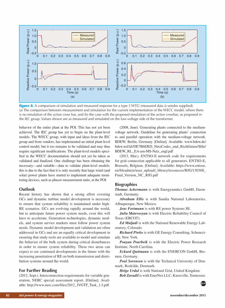
As mentioned above, the IEC effort is quite similar to the WECC approach. Several members active in both groups have worked to ensure coordination between the efforts to the extent possible. The key differences at present are in the type 3 model. These differences originate in the distinction between the validation philosophies of the United States and
Europe, as explained above. To give one example, consider Figure 8. In this figure, we see one of the type 3 technologies, an ac-side power electronic protection circuit referred to as an “active crow bar.” Not all type 3 designs use this feature; some employ dc choppers, and others simply over rate the converter and use neither. So this particular discrepancy is limited to one control design approach. Based on an over-whelming majority decision, the WECC group decided that the level of detail pertaining to the action of the active crow-bar did not warrant the significant added complexity in the model. Furthermore, all (including those in the IEC group) agree that the model only offers a rather simple emulation and that the parameters may be dependent on operating con-dition. To truly and faithfully model the action of the active crowbar, detailed three-phase models are needed.
The ultimate goal of the modeling efforts is to have suit-able models for WPPs that adequately represent the dynamic
1.5
1.0
0.5
Rea
l Pow
er (p
.u.)
Rea
ctiv
e Po
wer
(p.u
.)
0
1.51.0
0.5
−0.5
0
0 0.5 1 1.5 2 2.5 3
0 0.5 1 1.5Time (s)
(b)
Time (s)(a)
2 2.5 3
MeasuredEPRI WTGMV Commercial Tool
figure 7. A comparison of simulation and measured response for a type 4 WTG (measured data are vendor-supplied); the response to a voltage dip at the high-voltage side of the WTG step-up transformer is shown. The blue line is the original mea-sured data. The red dashed line is a simulation based on the Electric Power Research Institute’s WTGMV tool. The green line is the simulation with the beta implementation of the model by a commercial software vendor. Values shown are as measured and simulated on the low-voltage side of the transformer.
The ultimate goal of the modeling efforts is to have suitable models for WPPs that adequately represent the dynamic behavior of the entire plant at the point of common coupling.
82 ieee power & energy magazine november/december 2013
behavior of the entire plant at the POI. This has not yet been achieved. The IEC group has yet to begin on the plant-level models. The WECC group, with input and ideas from the IEC group and from vendors, has implemented an initial plant-level control model, but it too remains to be validated and may thus require significant modifications. The plant-level models speci-fied in the WECC documentation should not yet be taken as validated and finalized. One challenge has been obtaining the necessary—and suitable—data to validate plant-level models; this is due to the fact that it is only recently that large wind (and solar) power plants have started to implement adequate moni-toring devices, such as phasor measurement units, at the POI.
OutlookRecent history has shown that a strong effort covering GCs and dynamic turbine model development is necessary to ensure that system reliability is maintained under high-RE scenarios. GCs are evolving rapidly around the world, but to anticipate future power system needs, even this will have to accelerate. Generation technologies, dynamic mod-els, and system service markets must follow power system needs. Dynamic model development and validation are often addressed in GCs and are an equally critical development in ensuring that study tools are available to model and simulate the behavior of the bulk system during critical disturbances in order to ensure system reliability. These two areas can expect to see continued developments in the future with the increasing penetration of RE on both transmission and distri-bution systems around the world.
For Further Reading (2012, Sept.). Interconnection requirements for variable gen-eration, NERC special assessment report. [Online]. Avail-able: http://www.nerc.com/files/2012_IVGTF_Task_1-3.pdf
(2008, June). Generating plants connected to the medium-voltage network, Guideline for generating plants’ connection to and parallel operation with the medium-voltage network. BDEW, Berlin, Germany. [Online]. Available: www.bdew.de/bdew.nsf/id/DE7B6ERD_NetzCodes_und_Richtlinien/$file/BDEW_RL_EA-am-MS-Netz_engl.pdf
(2013, Mar.). ENTSO-E network code for requirements for grid connection applicable to all generators. ENTSO-E, Brussels, Belgium. [Online]. Available: https://www.entsoe.eu/fileadmin/user_upload/_library/resources/RfG/130308_Final_Version_NC_RfG.pdf
BiographiesThomas Ackermann is with Energynautics GmbH, Darm-stadt, Germany.
Abraham Ellis is with Sandia National Laboratories, Albuquerque, New Mexico.
Jens Fortmann is with RE power Systems SE.Julia Matevosyan is with Electric Reliability Council of
Texas (ERCOT).Ed Muljadi is with the National Renewable Energy Lab-
oratory, Colorado.Richard Piwko is with GE Energy Consulting, Schenect-
ady, New York.Pouyan Pourbeik is with the Electric Power Research
Institute, North Carolina.Eckard Quitmann is with the ENERCON GmbH, Bre-
men, Germany.Poul Sorensen is with the Technical University of Den-
mark, Roskilde, Denmark.Helge Urdal is with National Grid, United Kingdom.Bob Zavadil is with EnerNex LLC, Knoxville, Tennessee.
p&e
1.51.00.5
Rea
l Pow
er (p
.u.)
Rea
ctiv
e Po
wer
(p.u
.)
0
0 0.1 0.2 0.3 0.4 0.5 0.6 0.7 0.8
Measured
0.9
0 0.1 0.2 0.3 0.4 0.5Time (s)
0.6 0.7 0.8 0.9
−0.5
1.51.00.5
Rea
l Pow
er (p
.u.)
Rea
ctiv
e Po
wer
(p.u
.)
0
0 0.1 0.2 0.3 0.4 0.5 0.6 0.7 0.8 0.9
0 0.1 0.2 0.3 0.4 0.5Time (s)
(a) (b)
0.6 0.7 0.8 0.9
−0.5
1.0
0.5
0
−0.5
0.60.4
0.20
−0.2
SimulatedMeasuredSimulated
figure 8. A comparison of simulation and measured response for a type 3 WTG (measured data is vendor supplied). (a) The comparison between measurement and simulation for the current implementation of the WECC model, where there is no emulation of the active crow bar, and (b) the case with the proposed emulation of the active crowbar, as proposed in the IEC group. Values shown are as measured and simulated on the low-voltage side of the transformer.