coastal inlet bank erosion - defense technical … · coastal inlet bank erosion william ... a...
TRANSCRIPT

Proceedings, 2001National Conference on Beach Preservation Technology, pp. 274-283
COASTAL INLET BANK EROSION
William C. Seabergh1
Abstract: Much focus is placed on beach erosion on the open coast. However, coastal processes often occur on sandy shorelines interior to inlets that can lead to severe erosion. These shorelines lie adjacent to coastal inlets and extend around the inlet from the ocean to bay. In particular, an examination of coastal inlets with jetties or terminal groins that are connected to a sandy shoreline develop inner-bank erosion in the absence of preventive measures. Many mature projects show eroded regions that required extensive revetment. Typically, if the erosion is permitted to proceed unabated, a crenulate-shaped shoreline region will develop from the terminus of the jetty, extending both bayward and laterally into the adjacent beach. This expansion of erosion leads to loss of property and difficulties in reclamation as a shallow water environment develops. The eroded sediment moves into the channel creating shoaling problems. Many times the eroded region may flank the jetty structure, leaving it isolated from the shore. Isolation of the jetty may lead to potential problems of tidal current scour near the structure, opening the already eroded embayment to increased wave activity and additional erosion, and permitting increased wave attack on the jetty itself. As part of the Coastal Inlets Research Program (U.S. Army Corps of Engineers), this type of erosion was studied in a movable bed physical model of an inlet. After the governing processes were understood, several preventive techniques were investigated. A case study is included. INTRODUCTION
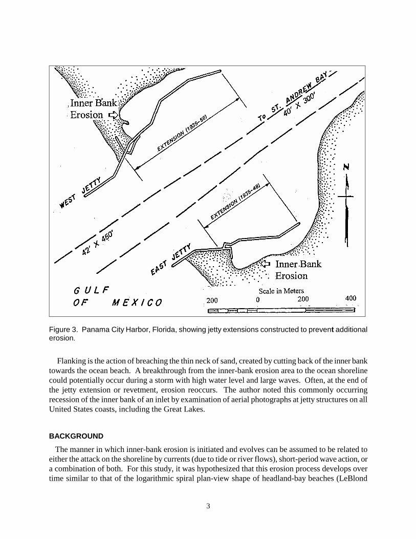
Examination of maps and photographs of many coastal inlets reveals a characteristic curved eroded shoreline on the inner-bank, or channel side of a jetty where it terminates in a sandy shore. At many inlets, that region of lateral expansion shoreward of the jetty terminus has been revetted or protected in some way with rock, bulkheads, or sheet-pile structures. The result of this erosion process is shown at St. George Inlet, Florida, which is located on the Gulf Coast in the eastern part of the Florida panhandle. Figure 1 shows the inlet in its natural state, and Figure 2 shows the inlet a few years after parallel jetties were constructed. Erosive forces have created the curved shorelines at the base of the jetties. Figure 3 shows the entrance channel at Panama City Harbor, Florida, created by cutting through an elongated spit in 1933. The construction included jetties extending to the -3.7 m, mllw (mean lower low water) contour. The inner 90 m of the jetties flared outward and were anchored in sand. Between 1935 and 1956, landward extensions of the jetties were made to prevent continued erosion of the inner-bank shoreline. Flanking of the jetties was a major concern.
1) U.S. Army Engineer Research and Development Center, Coastal and Hydraulics Laboratory, 3909 Halls
Ferry Road, Vicksburg, MS 39180-6199 USA. [email protected]

Report Documentation Page Form ApprovedOMB No. 0704-0188
Public reporting burden for the collection of information is estimated to average 1 hour per response, including the time for reviewing instructions, searching existing data sources, gathering andmaintaining the data needed, and completing and reviewing the collection of information. Send comments regarding this burden estimate or any other aspect of this collection of information,including suggestions for reducing this burden, to Washington Headquarters Services, Directorate for Information Operations and Reports, 1215 Jefferson Davis Highway, Suite 1204, ArlingtonVA 22202-4302. Respondents should be aware that notwithstanding any other provision of law, no person shall be subject to a penalty for failing to comply with a collection of information if itdoes not display a currently valid OMB control number.
1. REPORT DATE 2001 2. REPORT TYPE
3. DATES COVERED 00-00-2001 to 00-00-2001
4. TITLE AND SUBTITLE Coastal Inlet Bank Erosion
5a. CONTRACT NUMBER
5b. GRANT NUMBER
5c. PROGRAM ELEMENT NUMBER
6. AUTHOR(S) 5d. PROJECT NUMBER
5e. TASK NUMBER
5f. WORK UNIT NUMBER
7. PERFORMING ORGANIZATION NAME(S) AND ADDRESS(ES) U.S. Army Engineer Research and Development Center,Coastal andHydraulics Laboratory,3909 Halls Ferry Road,Vicksburg,MS,39180-6199
8. PERFORMING ORGANIZATIONREPORT NUMBER
9. SPONSORING/MONITORING AGENCY NAME(S) AND ADDRESS(ES) 10. SPONSOR/MONITOR’S ACRONYM(S)
11. SPONSOR/MONITOR’S REPORT NUMBER(S)
12. DISTRIBUTION/AVAILABILITY STATEMENT Approved for public release; distribution unlimited
13. SUPPLEMENTARY NOTES 2001 National Conference on Beach Preservation Technology, pp. 274-283
14. ABSTRACT Much focus is placed on beach erosion on the open coast. However, coastal processes often occur on sandyshorelines interior to inlets that can lead to severe erosion. These shorelines lie adjacent to coastal inletsand extend around the inlet from the ocean to bay. In particular, an examination of coastal inlets withjetties or terminal groins that are connected to a sandy shoreline develop inner-bank erosion in the absenceof preventive measures. Many mature projects show eroded regions that required extensive revetment.Typically, if the erosion is permitted to proceed unabated, a crenulate-shaped shoreline region will developfrom the terminus of the jetty, extending both bayward and laterally into the adjacent beach. Thisexpansion of erosion leads to loss of property and difficulties in reclamation as a shallow waterenvironment develops. The eroded sediment moves into the channel creating shoaling problems. Manytimes the eroded region may flank the jetty structure, leaving it isolated from the shore. Isolation of thejetty may lead to potential problems of tidal current scour near the structure, opening the already erodedembayment to increased wave activity and additional erosion, and permitting increased wave attack on thejetty itself. As part of the Coastal Inlets Research Program (U.S. Army Corps of Engineers), this type oferosion was studied in a movable bed physical model of an inlet. After the governing processes wereunderstood, several preventive techniques were investigated. A case study is included.
15. SUBJECT TERMS
16. SECURITY CLASSIFICATION OF: 17. LIMITATION OF ABSTRACT Same as
Report (SAR)
18. NUMBEROF PAGES
10
19a. NAME OFRESPONSIBLE PERSON
a. REPORT unclassified
b. ABSTRACT unclassified
c. THIS PAGE unclassified

Figure 1. St. George Island Channel, Florida, before jetties (1955).
2
Figure 2. St. George Island Channel 12 years after jetties were constructed (1969). Note inner bank erosion on both sides of channel. The eroded area on right side is approximately 90 m into the bank line and 210 m in the along-channel direction.
3
Figure 3. Panama City Harbor, Florida, showing jetty extensions constructed to prevent additional erosion.
Flanking is the action of breaching the thin neck of sand, created by cutting back of the inner bank towards the ocean beach. A breakthrough from the inner-bank erosion area to the ocean shoreline could potentially occur during a storm with high water level and large waves. Often, at the end of the jetty extension or revetment, erosion reoccurs. The author noted this commonly occurring recession of the inner bank of an inlet by examination of aerial photographs at jetty structures on all United States coasts, including the Great Lakes.
BACKGROUND
The manner in which inner-bank erosion is initiated and evolves can be assumed to be related to either the attack on the shoreline by currents (due to tide or river flows), short-period wave action, or a combination of both. For this study, it was hypothesized that this erosion process develops over time similar to that of the logarithmic spiral plan-view shape of headland-bay beaches (LeBlond

4
1979) or the crenulate bay (Silvester 1970). Dean and Maurmeyer (1977) examined an erosion spot inside Shinnecock Inlet, N.Y., and concluded waves, not currents, were the causative agent. Walton (1977) produced an analytic method relating wave-height energy distribution to predict stable sheltered shoreline. Moreno and Kraus (1999) developed a hyperbolic-tangent function to fit these shoreline shapes.
These erosion processes occur on the open coast, and wave diffraction and refraction create the crenulate shape. Eventually, an equilibrium shape is achieved for a given wave condition or dominant wave condition. This equilibrium shape implies that the shoreline reaches a stable shape and erosion ceases. The inner bank of an inlet is more easily exposed to the potential of erosion by tidal or riverine currents and short period wind waves and/or boat-generated waves. There is some question as to the dominant process and mechanisms causing inner bank erosion. Laboratory experiments were conducted to determine how the inner-bank shoreline responds to these processes.
LABORATORY STUDY OF INNER-BANK EROSION Laboratory Setup. A coastal inlet was designed within a 46 m wide by 99 m long concrete basin with 0.6 m high walls (Figure 4). The approach was to design an idealized inlet with simplified .
Figure 4. Coastal Inlet Research Program laboratory and model facility.

5
bathymetry and steep beach slopes so additional features (such as an ebb shoal) could easily be added. In addition, a fine sand (placed over the concrete bottom in a thick veneer) served as both a tracer and as a fully mobile bed. A 1:50 undistorted scale was assumed to determine reasonable inlet dimensions to model; however, other scales can be assumed to accommodate study of specific processes with the simplified bathymetry. For this study a fully movable-bed was placed along the entrance channel, from a region just inside the jetties bayward.
Modeled Conditions. The approach was to run initially with a wave-only condition, followed by waves with a steady-state flood current, and then waves with a tide (scaled at 1:50). The wave generator was oriented perpendicular to the channel centerline. Initially, the rock jetties were permeable, but were made impermeable with thin aluminum sheeting placed vertically along the length of the jetty centerline. This eliminated sand from the beaches passing through the permeable structure and reaching the channel and changing channel bathymetry. For the wave-only and wave-plus-steady-state current runs, the water level was +1.5 m relative to mean low water (mlw). The semidiurnal tide level varied between 0.0 and +1.5 m, mlw, with a period of 105.4 min (Froude time scale = 1:7.07, model to prototype). The initial condition for the movable-bed portion of the bathymetry was composed of two different side-slopes for the inner-bank on each side of the channel.
Inner-Bank Erosion Experiment. The first wave condition was chosen as 2.7-m height, 10-sec period (scaled to prototype), and no currents were reproduced. The model was run until equilibrium plan view and vertical profile shape were reached for the given wave and water level, and then the bathymetry was measured. For this wave-only condition, the lateral run-up produced by the water level variation as wave crests, then troughs, moved past the terminal end of the structure, initiated the erosion at the jetty terminus. The run-up and run-down motion at the tip of the landward terminus of the jetty created a notch in the sand, which gradually deepened, then widened, permitting increasing wave diffraction to carve out the embayment. The erosion region developed from a straight bank line into the crenulate shaped embayments as seen in Figure 5. The eroded region reached an equilibrium shape after about 20 hours model time. The addition of currents with the waves increased the size of the embayment, but the initiating process was observed to be the same as the no-current experiment. Sediment eroded from the embayment moved along the edge of the inlet channel. With the no-current condition, sediment built out into the center of the entrance channel and reduced the rate of removal from the eroded region. The flood current increased the angle of wave attack and movement of sediment out of the embayment. With a tide plus waves condition, a similar shape embayment formed as for previous conditions, larger than the no current condition, but smaller than the wave plus steady-state flood current. The variation in tidal elevation permitted a deeper cut in the embayment. With currents (steady-state or tidal) present, the eroded volumes increased in the range of 8 to 45 percent. Inner-Bank Erosion Prevention Methods. Follow-up experiments examined potential solutions to minimize erosion by placing hardpoints to create smaller embayments or altering jetty structure slope and lateral extension into the channel. A diamond shape (in plan view) was built on the end of the right jetty and functioned to reduce wave energy at the end of the jetty. Because of its extension into the beach, it also prevented flanking, as shown in Figure 6, top photo, right side. On the left side

6
Figure 5. Waves entering the jettied entrance channel and producing crenulate-shaped (eroded) embayments.
of the top photo, Figure 6, a channel-side structure is placed seaward from the jetty terminus, and flanking of the jetty occurred because there was no tie-in to the beach. The headland concept was adopted by adding a hardpoint (a rock mound) on a line bayward of the jetty, to create a smaller embayment region than was created without the additional structure (Figure 6, bottom photo). These are compared to the non-structure experiment in Figure 5 for wave and tidal current conditions. Volumes eroded and surface area removed was reduced for the prevention methods. The diamond structure clearly reduced erosion and prevented flanking of the structure, reducing volume loss 58 and 47 percent on the right (initially steep slope) and left (initially relatively flat slope) inner-bank regions, respectively.
CASE STUDY OF INNER BANK EROSION AND A SOLUTION Grays Harbor, on the Pacific Coast of Washington, has a large entrance channel. South jetty construction commenced in 1898 and north jetty construction was completed in 1913. By 1929, the inlet entrance was as shown in the top map of Figure 7. Focussing attention on the shore end of the south jetty, which had a crest elevation of +2.4 m, mllw, there was a continuous shoreline from ocean-side to bayside at the south jetty junction with the shore. Apparently, in this region of high wave climate (average significant wave height of 2 m, with storm waves of 5 m not unusual) and large tide range (diurnal tide range of 2.7 m), sediment can move over and through the jetty at the
Ocean
Beach
Jetty JettyChannel
Inner BankErosionRegion

7
shoreline during high water and storm conditions. Earlier maps of the inlet, after the jetties were built, showed this continuous shoreline through the south jetty also. In the 1936-1939 time frame, the south jetty crest elevation was increased to +6.1 m, mllw. This addition in elevation was sufficient to reduce or cut off the sediment supply from the beaches to the inner bank shoreline. As seen in Figure 7, initially the inner bank was receding eastward, and by 1946 the jetty terminus was exposed. An eroded region evolved at the south jetty terminus, as seen in the 1960 timeframe. In1960, the curved notch extended approximately 640 m landward from the jetty terminus, and was recessed
Figure 6. Top photo shows "diamond" end (right side) and a seaward diffraction structure (left side) and bottom photo shows a mound structure on each side, bayward of jetties.

8
200 m laterally into the inner bank. By 1993, the eroded region had increased to dimensions of 730 m long by 275 m wide. From 1946 to 1960, it expanded at a rate of about 46 m/year in length and 14 m/year in width. From 1960 to 1993, the rate of increase was reduced significantly. In late 1993, the region just south of the south jetty was breached during a storm, and emergency measures had to be taken to repair the breach. The navigation channel was in close proximity, located on the inner edge of the south jetty, and tidal flow could potentially enlarge the breach and cause additional erosion to the region. Increased exposure to wave action was also a possibility for the City of Westport, located east of the eroded area. The ocean-side beach had also been receding, so the combination of inner bank erosion and beach recession greatly increased the potential for breaching. The gap was filled with dredged material in this emergency. To prevent a reoccurrence of the breakthrough, the Seattle District, U.S. Army Corps of Engineers designed a mound structure based on the conceptual model experiments of the Coastal Inlets Research Program described above. A model study was conducted
Elevation of top of jetty + 20 ft Elevation of top of jetty <+20 ft
Aug 1929
Aug 1960
Figure 7. Grays Harbor, Washington, entrance. August 1929, before South Jetty shoreward portion raised and Aug 1960 about 24 years after south jetty raised to + 20 ft. Note creation of inner bank erosion area.

to replicate the shoreward region of the south jetty and some of the navigation channel in the laboratory facility. This work confirmed the design. Figure 8 shows the existing condition in the model and the plan selected for construction. The wave angle sweeping along the shoreline is modified by the mound, directing it more perpendicular to the inner bank shoreline. Also wave heights were significantly reduced in this region. Figure 9 shows the structure as constructed in 1999.
Figure 8. Model study photos: left photo shows the pre-diffraction structure condition and right photo the mound structure diffracting waves.
Figure 9. Mound diffraction structure as constructed at Grays Harbor, Half Moon Bay.
9

10
CONCLUSIONS
Inner-bank erosion, which occurs at the shoreward termination of a jetty structure on the channel side of an inlet in a sandy beach, occurs on all United States coasts. An unabated eroded area takes the shape of a crenulate or log-spiral beach, similar to that which occurs on the open coast downdrift of headland features. Investigations in a movable-bed physical model basin have shown that the erosion is a consequence primarily of wave action, which initially cuts a trough at the jetty structure-sandy shoreline intersection then gradually widens, allowing diffracted wave energy to widen the trough, both behind the structure and bayward. Waves refracting up the side of the channel slope then continue to elongate the eroded region. An equilibrium shape is reached similar to the open coast crenulate bay. If a flood-flow current is added to the wave environment, the wave angle becomes steeper and sand at the landward end of the embayment is pushed further inland along the channel's edges. The waves plus current results in a larger equilibrium embayment than for waves-only. For a tide-plus-waves condition, the erosion area is greater than the waves-only condition, but less than the waves plus steady flood current condition.
Laboratory experiments were performed to examine solutions for reducing the erosion other than the traditional revetment of the shoreline with armor stone. A hard-point stone mound placed some distance bayward of the jetty termination created a shoreline response similar to that of headland beaches, creating smaller embayments rather than one large deep-cutting embayment. A diamond-shaped rock mound on the jetty termination location functioned best, especially because of its projection into the beach-side of the jetty. The diamond-shaped mound prevented flanking of the terminal tip of the jetty. Its projection into the channel reduced wave height at the structure-sand interface. The experiments were conceptual in nature and conducted for limited conditions. Future work should examine many different wave conditions. The site-specific design of a terminal rock mound for Half Moon Bay, Grays Harbor, Washington, was evaluated in the inlet laboratory facility. The final design was constructed in 2000. ACKNOWLEDGEMENTS
The work was conducted under the Inlet Laboratory Investigations work unit, Coastal Inlets Research Program. Permission to publish was granted by the Office, Chief of Engineers. Thanks to Ms. Julie Rosati, Mr. Dennis Markle, and Dr. Nicholas Kraus for review comments.
REFERENCES
Dean, R.G .and Maurmeyer, E.M.. 1977. Predictability of characteristics of two embayments. Proceedings of Coastal Sediments ‘77, ASCE, 848-866.
Keulegan, G.H., 1967. Tidal flow in entrances, water-level fluctuations of basins in communication with seas, Technical Bulletin No. 14, Committee on Tidal Hydraulics, Corps of Engineers, U.S. Army.
LeBlond, P.H., 1979. An explanation of the logarithmic spiral plan shape of headland-bay beaches, Journal of Sedimentary Petrology, v.49, no.4, 1093-1100, December.
Moreno, L.J. and Kraus, N.C., 1999. Equilibrium shape of headland-bay beaches for engineering design. Proceedings of Coastal Sediments ‘99, ASCE, 860-875.
Silvester, R., 1970. Growth of crenulate-shaped bays to equilibrium, Proc. ASCE, 96(WW2), 275-287.
Walton, T.L., 1977. Equilibrium shores and coastal design. Proceedings of Coastal Sediments ‘77, ASCE, 1-15.