coal creek and rock creek major drainageway plan
TRANSCRIPT

COAL CREEK AND ROCK CREEK MAJOR DRAINAGEWAY PLAN Project Sponsors:
Prepared by:
October 2014
720 South Colorado Boulevard Suite 410 S Denver, Colorado 80246 phone (303) 757-3655 fax (303) 300-1635
BOULDER COUNTY
CITY AND COUNTY OF BROOMFIELD
TOWN OF ERIE
URBAN DRAINAGE AND FLOOD CONTROL DISTRICT
CITY OF LAFAYETTE
CITY OF LOUISVILLE
TOWN OF SUPERIOR

THIS PAGE HAS BEEN INTENTIONALLY LEFT BLANK.

RESPEC Consulting & Services 720 South Colorado Boulevard, Suite 410 S
Denver, CO 80246
COAL CREEK AND ROCK CREEK MAJOR DRAINAGEWAY PLAN
October 2014 Ms. Shea Thomas Manager of Master Planning Urban Drainage and Flood Control District 2480 West 26th Avenue, Suite 156-B Denver, CO 80211 Subject: Coal Creek and Rock Creek Major Drainageway Plan UDFCD Agreement No. 12-01.17 Dear Ms. Thomas: RESPEC Consulting & Services is pleased to submit this report, titled Coal Creek and Rock Creek Major Drainageway Plan, dated October 14, 2014. We would like to acknowledge the help and support in the preparation of this report that was furnished by Boulder County, the City and County of Broomfield, the Town of Erie, the City of Lafayette, the City of Louisville, and the Town of Superior. In order to minimize the impacts of flooding, this conceptual design lays out strategies for drainage and conveyance within the study area. The recommendations improve the conveyance efficiency and water quality as well as reduce the flood hazards and erosion along Coal Creek and Rock Creek. The enclosed text and drawings present the improvements in our conceptual design for the Coal Creek and Rock Creek drainageways. These improvements consist of open channels, bank stabilization, culverts, and bridges.
Thank you for the opportunity to complete this project. Best regards, RESPEC Consulting & Services _____________________________________________________________ Rick R. Moser, P.E. Principal _____________________________________________________________ David P. Delagarza, P.E. Project Manager _____________________________________________________________ Tony H. Tran, E.I. Project Engineer _____________________________________________________________ Michael J. Bannister Project Engineer

THIS PAGE HAS BEEN INTENTIONALLY LEFT BLANK.

TABLE OF CONTENTS
i
COAL CREEK AND ROCK CREEK MAJOR DRAINAGEWAY PLAN
Executive Summary .................................................................................................... ES-1
ES.1 Purpose and Objectives ..................................................................................................................... ES-1 ES.2 Planning Process ................................................................................................................................ ES-1 ES.3 Project Area ....................................................................................................................................... ES-3 ES.4 Hydrologic Analysis ............................................................................................................................ ES-3 ES.5 Hydraulic Analysis .............................................................................................................................. ES-4 ES.6 Alternatives Evaluation ...................................................................................................................... ES-4 ES.7 Recommended Plan ........................................................................................................................... ES-5 ES.8 Selected Plan and Conceptual Design ................................................................................................ ES-5
Section 1 Introduction .......................................................................................... 1-1
1.1 Authorization ...................................................................................................................................... 1-1 1.2 Purpose and Scope ............................................................................................................................. 1-1 1.3 Planning Process ................................................................................................................................. 1-1 1.4 Mapping and Surveys .......................................................................................................................... 1-1 1.5 Data Collection .................................................................................................................................... 1-2 1.6 Acknowledgements ............................................................................................................................ 1-2
Section 2 Study Area ............................................................................................ 2-1
2.1 Project Area ........................................................................................................................................ 2-1 2.2 Land Use .............................................................................................................................................. 2-2 2.3 Reach Description ............................................................................................................................... 2-2 2.4 Flood History ...................................................................................................................................... 2-3 2.5 Environmental Assessment ................................................................................................................. 2-4
Section 3 Hydrologic Analysis .............................................................................. 3-1
3.1 Overview ............................................................................................................................................. 3-1 3.2 Design Rainfall..................................................................................................................................... 3-1 3.3 Subwatershed Characteristics ............................................................................................................ 3-1
3.3.1 Subwatershed Delineation .................................................................................................... 3-1 3.3.2 Watershed Imperviousness ................................................................................................... 3-2 3.3.3 Soils Information .................................................................................................................... 3-2
3.4 Hydrograph Routing ............................................................................................................................ 3-2 3.5 Previous Studies .................................................................................................................................. 3-2 3.6 Results of Analysis ............................................................................................................................... 3-3
Section 4 Hydraulic Analysis ................................................................................ 4-1
4.1 Evaluation of Existing Facilities ........................................................................................................... 4-1 4.2 Flood Hazards ..................................................................................................................................... 4-2 4.3 Previous Analyses ............................................................................................................................... 4-2
Section 5 Alternatives Analysis ............................................................................ 5-1
5.1 Alternative Development Process ...................................................................................................... 5-1 5.1.1 Criteria and Constraints ......................................................................................................... 5-1
5.2 Alternative Categories ......................................................................................................................... 5-1 5.2.1 Initial Screening of Alternative Plans ...................................................................................... 5-1
5.3 Roadway Crossing and Channel Stability Improvements .................................................................... 5-4 5.4 Alternative Hydraulics ......................................................................................................................... 5-4 5.5 Alternative Costs .................................................................................................................................. 5-4 5.6 Alternative Plans .................................................................................................................................. 5-5
5.6.1 Coal Creek Reach 1: Downstream Study Limit (Boulder Creek) to Kenosha Road ............... 5-15 5.6.2 Coal Creek Reach 2: Kenosha Road to East County Line Road ............................................. 5-15 5.6.3 Coal Creek Reach 3: East County Line Road to Old Railroad Tracks ..................................... 5-16 5.6.4 Coal Creek Reach 4: Old Railroad Tracks to Briggs Street .................................................... 5-17 5.6.5 Coal Creek Reach 5: Briggs Street to Cheesman Street ........................................................ 5-18 5.6.6 Coal Creek Reach 6: Cheesman Street to Erie Parkway ....................................................... 5-18 5.6.7 Coal Creek Reach 7: Erie Parkway to North of Irrigation Pond ............................................ 5-19 5.6.8 Coal Creek Reach 8: North of Irrigation Pond to South of Irrigation Pond .......................... 5-20 5.6.9 Coal Creek Reach 9: South of Irrigation Pond to Vista Parkway ........................................... 5-20 5.6.10 Coal Creek Reach 10: Vista Parkway to Taxiway Bridge Near Airport .................................. 5-21 5.6.11 Coal Creek Reach 11: Taxiway Bridge Near Airport to Boulder County/
Weld County Boundary ......................................................................................................... 5-22 5.6.12 Coal Creek Reach 12: Boulder County/Weld County Boundary to Baseline Road ............... 5-23 5.6.13 Coal Creek Reach 13: Baseline Road to Pedestrian Bridge Near Flagg Park Boundary ........ 5-24 5.6.14 Coal Creek Reach 14: Pedestrian Bridge Near Flagg Park Boundary to Boulder County/
Lafayette Boundary .............................................................................................................. 5-25 5.6.15 Coal Creek Reach 15: Boulder County/Lafayette Boundary to Confluence of
Coal Creek and Rock Creek ................................................................................................... 5-25 5.6.16 Coal Creek Reach 20: Confluence of Coal Creek and Rock Creek to Lafayette/
Boulder County Boundary .................................................................................................... 5-26 5.6.17 Coal Creek Reach 21: Lafayette City/Boulder County Boundary to Boulder County/
Lafayette Boundary .............................................................................................................. 5-27 5.6.18 Coal Creek Reach 22: Boulder County/Lafayette Boundary to Lafayette/
Boulder County Boundary .................................................................................................... 5-27 5.6.19 Coal Creek Reach 23: Lafayette/Boulder County Boundary to South Public Road .............. 5-28 5.6.20 Coal Creek Reach 24: South Public Road to Highway 287 .................................................... 5-29 5.6.21 Coal Creek Reach 25: Highway 287 to Lafayette/Louisville Boundary ................................. 5-30 5.6.22 Coal Creek Reach 26: Lafayette/Louisville Boundary to 96th Street .................................... 5-30 5.6.23 Coal Creek Reach 27: 96th Street to CC Golf Course Pedestrian Bridge .............................. 5-31 5.6.24 Coal Creek Reach 28: CC Golf Course Pedestrian Bridge to Highway 36.............................. 5-32 5.6.25 Coal Creek Reach 29: Highway 36 to McCaslin Boulevard ................................................... 5-33 5.6.26 Coal Creek Reach 30: McCaslin Boulevard to Superior/Boulder County Boundary ............. 5-33 5.6.27 Coal Creek Reach 31: Superior/Boulder County Boundary to 1.2 Miles Upstream ............. 5-34 5.6.28 Coal Creek Reach 32: 1.2 Miles Upstream to 3.1 Miles Upstream ....................................... 5-34 5.6.29 Coal Creek Reach 33: 3.1 Miles Upstream to Highway 128 ................................................. 5-35 5.6.30 Rock Creek Reach 40: Confluence of Coal Creek and Rock Creek to 120th Street............... 5-36 5.6.31 Rock Creek Reach 41: 120th Street to Drainageway F ......................................................... 5-36 5.6.32 Rock Creek Reach 42: Drainageway F to Lafayette/Boulder County Boundary ................... 5-37 5.6.33 Rock Creek Reach 43: Lafayette/Boulder County Boundary to Dillon Road ........................ 5-38 5.6.34 Rock Creek Reach 44: Dillon Road (EB) to Dillon Road (WB) ................................................ 5-38 5.6.35 Rock Creek Reach 45: Dillon Road (WB) to Highway 287 ..................................................... 5-39 5.6.36 Rock Creek Reach 46: Highway 287 to East of Stearns Lake ................................................ 5-40 5.6.37 Rock Creek Reach 47: East of Stearns Lake to 104th Street ................................................. 5-40 5.6.38 Rock Creek Reach 48: 104th Street to Brainard Drive .......................................................... 5-41

TABLE OF CONTENTS
ii
COAL CREEK AND ROCK CREEK MAJOR DRAINAGEWAY PLAN
5.6.39 Rock Creek Reach 49: Brainard Drive to Highway 36 .......................................................... 5-41 5.6.40 Rock Creek Reach 50: Highway 36 to Superior/Broomfield Boundary ................................ 5-42 5.6.41 Rock Creek Reach 51: Superior/Broomfield Boundary to Irrigation Structure.................... 5-43 5.6.42 Rock Creek Reach 52: Irrigation Structure to Superior/Boulder County Boundary ............ 5-43 5.6.43 Rock Creek Reach 53: Superior/Boulder County Boundary to Upstream Study Limit ........ 5-44
5.7 Qualitative Evaluation Procedure ..................................................................................................... 5-45 5.7.1 Benefit-Cost Analysis ........................................................................................................... 5-45
Section 6 Recommended Plan .............................................................................. 6-1
6.1 Plan Description .................................................................................................................................. 6-1 6.2 Water Quality Impacts ........................................................................................................................ 6-1 6.3 Operations and Maintenance ............................................................................................................. 6-2 6.4 Environmental and Safety Assessment ............................................................................................... 6-2 6.5 Cultural Assessment and Preservation ............................................................................................... 6-2
Section 7 Conceptual Design of Selected Plan .................................................... 7-1
7.1 Conceptual Design Overview .............................................................................................................. 7-1 7.2 Design Criteria ..................................................................................................................................... 7-1 7.3 Stream Stabilization ............................................................................................................................ 7-2
7.3.1 Bank Stabilization Criteria and Constraints ........................................................................... 7-3 7.3.2 Hard Bank Stabilization Measures ......................................................................................... 7-3 7.3.3 Soft Bank Stabilization Measures .......................................................................................... 7-3
7.4 Cost Estimate ...................................................................................................................................... 7-8 7.5 Conceptual Design Description ........................................................................................................... 7-8
7.5.1 Coal Creek Reach 1: Downstream Study Limit (Boulder Creek) to Kenosha Road .............. 7-13 7.5.2 Coal Creek Reach 2: Kenosha Road to East County Line Road ............................................ 7-15 7.5.3 Coal Creek Reach 3: East County Line Road to Old Railroad Tracks .................................... 7-17 7.5.4 Coal Creek Reach 4: Old Railroad Tracks to Briggs Street.................................................... 7-19 7.5.5 Coal Creek Reach 5: Briggs Street to Cheesman Street ....................................................... 7-20 7.5.6 Coal Creek Reach 6: Cheesman Street to Erie Parkway ....................................................... 7-22 7.5.7 Coal Creek Reach 7: Erie Parkway to North of Irrigation Pond ............................................ 7-23 7.5.8 Coal Creek Reach 8: North of Irrigation Pond to South of Irrigation Pond .......................... 7-25 7.5.9 Coal Creek Reach 9: South of Irrigation Pond to Vista Parkway .......................................... 7-27 7.5.10 Coal Creek Reach 10: Vista Parkway to Taxiway Bridge Near Airport ................................. 7-28 7.5.11 Coal Creek Reach 11: Taxiway Bridge Near Airport to Boulder County/
Weld County Boundary ....................................................................................................... 7-30 7.5.12 Coal Creek Reach 12: Boulder County/Weld County Boundary to Baseline Road .............. 7-32 7.5.13 Coal Creek Reach 13: Baseline Road to Pedestrian Bridge Near Flagg Park Boundary ....... 7-34 7.5.14 Coal Creek Reach 14: Pedestrian Bridge Near Flagg Park Boundary to Boulder County/
Lafayette Boundary .............................................................................................................. 7-36 7.5.15 Coal Creek Reach 15: Boulder County/Lafayette Boundary to Confluence of
Coal Creek and Rock Creek .................................................................................................. 7-37 7.5.16 Coal Creek Reach 20: Confluence of Coal Creek and Rock Creek to Lafayette/
Boulder County Boundary .................................................................................................... 7-38 7.5.17 Coal Creek Reach 21: Lafayette /Boulder County Boundary to Boulder County/
Lafayette Boundary .............................................................................................................. 7-39 7.5.18 Coal Creek Reach 22: Boulder County/Lafayette Boundary to Lafayette/
Boulder County Boundary .................................................................................................... 7-41
7.5.19 Coal Creek Reach 23: Lafayette/Boulder County Boundary to South Public Road .............. 7-43 7.5.20 Coal Creek Reach 24: South Public Road to Highway 287 .................................................... 7-45 7.5.21 Coal Creek Reach 25: Highway 287 to Lafayette/Louisville Boundary ................................. 7-46 7.5.22 Coal Creek Reach 26: Lafayette/Louisville Boundary to 96th Street .................................... 7-48 7.5.23 Coal Creek Reach 27: 96th Street to CC Golf Course Pedestrian Bridge .............................. 7-50 7.5.24 Coal Creek Reach 28: CC Golf Course Pedestrian Bridge to Highway 36.............................. 7-52 7.5.25 Coal Creek Reach 29: Highway 36 to McCaslin Boulevard ................................................... 7-54 7.5.26 Coal Creek Reach 30: McCaslin Boulevard to Superior/Boulder County Boundary ............. 7-56 7.5.27 Coal Creek Reach 31: Superior/Boulder County Boundary to 1.2 Miles Upstream ............. 7-57 7.5.28 Coal Creek Reach 32: 1.2 Miles Upstream to 3.1 Miles Upstream ....................................... 7-59 7.5.29 Coal Creek Reach 33: 3.1 Miles Upstream to Highway 128 ................................................. 7-61 7.5.30 Rock Creek Reach 40: Confluence of Coal Creek and Rock Creek to 120th Street............... 7-63 7.5.31 Rock Creek Reach 41: 120th Street to Drainageway F ......................................................... 7-65 7.5.32 Rock Creek Reach 42: Drainageway F to Lafayette/Boulder County Boundary ................... 7-66 7.5.33 Rock Creek Reach 43: Lafayette/Boulder County Boundary to Dillon Road ........................ 7-67 7.5.34 Rock Creek Reach 44: Dillon Road (EB) to Dillon Road (WB) ................................................ 7-69 7.5.35 Rock Creek Reach 45: Dillon Road (WB) to Highway 287 ..................................................... 7-70 7.5.36 Rock Creek Reach 46: Highway 287 to East of Stearns Lake ................................................ 7-72 7.5.37 Rock Creek Reach 47: East of Stearns Lake to 104th Street ................................................. 7-73 7.5.38 Rock Creek Reach 48: 104th Street to Brainard Drive .......................................................... 7-72 7.5.39 Rock Creek Reach 49: Brainard Drive to Highway 36 ........................................................... 7-75 7.5.40 Rock Creek Reach 50: Highway 36 to Superior/Broomfield Boundary ................................ 7-77 7.5.41 Rock Creek Reach 51: Superior/Broomfield Boundary to Irrigation Structure .................... 7-78 7.5.42 Rock Creek Reach 52: Irrigation Structure to Superior/Boulder County Boundary ............. 7-80 7.5.43 Rock Creek Reach 53: Superior/Boulder County Boundary to Upstream Study Limit ......... 7-81
7.6 Prioritizing and Phasing ..................................................................................................................... 7-82 7.7 Water Quality Impacts ....................................................................................................................... 7-82 7.8 Environmental and Safety Assessment ............................................................................................. 7-82 7.9 Operation and Maintenance ............................................................................................................. 7-82 7.10 General Recommendations ............................................................................................................... 7-82
Section 8 References ............................................................................................ 8-1

TABLE OF CONTENTS
iii
COAL CREEK AND ROCK CREEK MAJOR DRAINAGEWAY PLAN
List of Tables
Table ES.4-1 Comparison of Peak Flows to Previous Studies ......................................................................... ES-4 Table ES.7-1 Conceptual Design Improvement Cost Estimate Summary by Reach ........................................ ES-7 Table ES.7-2 Conceptual Design Improvements Cost Estimate Summary by Jurisdiction.............................. ES-8 Table 2-1 Existing Land Use Imperviousness Values ........................................................................................ 2-2 Table 2-2 Future Land Use Imperviousness Values ......................................................................................... 2-2 Table 3.2-1 Point Rainfall Depths ..................................................................................................................... 3-1 Table 3.2-2 Rainfall Area Correction Factors ................................................................................................... 3-1 Table 3.3-1 Horton Infiltration Properties ....................................................................................................... 3-2 Table 3.6-1 Comparison of Peak Flows to Previous Studies ............................................................................ 3-3
Table 4-1 Roadway Culvert Overtopping Criteria ............................................................................................ 4-1 Table 4-2 Roadway and Trail Crossing Summary ............................................................................................. 4-3 Table 5.5-1 Unit Costs ...................................................................................................................................... 5-5 Tables 5.6.1-1 to 5.6.43-1 Reach Characteristics ............................................................................... 5-15 to 5-45 Tables 5.6.1-2 to 5.6.43-2 Alternatives Cost Summary ..................................................................... 5-15 to 5-45 Table 5.7-1 Benefit Rating System for Alternatives ...................................................................................... 5-46 Table 5.7-2 Alternatives Summary Evaluation Matrix ................................................................................... 5-47
Table 6-1 Recommended Plan Cost Estimate .................................................................................................. 6-1
Table 7.3.3-1 Reach Average Velocity and Shear Stress Characteristics ......................................................... 7-5 Table 7.3.3-2 Literature Review of Bioengineering Methods .......................................................................... 7-6 Table 7.3.3-3 Bioengineering Methods Reach Applicability ............................................................................ 7-7 Table 7.4-1 Conceptual Design Improvements Cost Estimate Summary by Jurisdiction ................................ 7-8 Tables 7.5.1-1 to 7.5.43-1 Reach Cost Estimates ............................................................................... 7-14 to 7-81
List of Figures
Figure ES-1 Study Area .................................................................................................................................... ES-2 Figure ES-2 Conceptual Design: Reaches 1-11 ................................................................................................ ES-9 Figure ES-3 Conceptual Design: Reaches 12-27, 40-48 ................................................................................. ES-10 Figure ES-4 Conceptual Design: Reaches 28-33 ............................................................................................ ES-11 Figure ES-5 Conceptual Design: Reaches 49-53 ............................................................................................ ES-12 Figure 2-1 Project Area Map ............................................................................................................................ 2-6 Figure 5.6-1 Reach Alternate Figure: Reaches 1-6 ........................................................................................... 5-7 Figure 5.6-2 Reach Alternate Figure: Reaches 7-12 ......................................................................................... 5-8 Figure 5.6-3 Reach Alternate Figure: Reaches 13-23, 40-44 ........................................................................... 5-9 Figure 5.6-4 Reach Alternate Figure: Reaches 24-27 ..................................................................................... 5-10 Figure 5.6-5 Reach Alternate Figure: Reaches 28-31 ..................................................................................... 5-11 Figure 5.6-6 Reach Alternate Figure: Reaches 32-33 ..................................................................................... 5-12 Figure 5.6-7 Reach Alternate Figure: Reaches 45-50 ..................................................................................... 5-13 Figure 5.6-8 Reach Alternate Figure: Reaches 50-53 ..................................................................................... 5-14
Figure 6-1 Recommended Plan Figure: Reaches 1-6 ........................................................................................ 6-3 Figure 6-2 Recommended Plan Figure: Reaches 7-12 ...................................................................................... 6-4 Figure 6-3 Recommended Plan Figure: Reaches 13-23, 40-44 ......................................................................... 6-5 Figure 6-4 Recommended Plan Figure: Reaches 24-27 .................................................................................... 6-6 Figure 6-5 Recommended Plan Figure: Reaches 28-31 .................................................................................... 6-7 Figure 6-6 Recommended Plan Figure: Reaches 32-33 .................................................................................... 6-8 Figure 6-7 Recommended Plan Figure: Reaches 45-50 .................................................................................... 6-9 Figure 6-8 Recommended Plan Figure: Reaches 50-53 .................................................................................. 6-10
Figure 7.5-1 Major Drainageway Plan Schematic Reach 1-11 .......................................................................... 7-9 Figure 7.5-2 Major Drainageway Plan Schematic Reach 12-27, 40-48 ........................................................... 7-10 Figure 7.5-3 Major Drainageway Plan Schematic Reach 28-33 ...................................................................... 7-11 Figure 7.5-4 Major Drainageway Plan Schematic Reach 49-53 ...................................................................... 7-12 Figure 7.5.1-1 Pipeline Crossing and Existing Drop Structure at Station 23+00 on Reach 1 .......................... 7-13 Figure 7.5.1-2 Meander Cutting Into Crop Land at Station 38+00 on Reach 1 .............................................. 7-14 Figure 7.5.2-1 Bank Erosion Cutting Towards Residential Structures at Richards Court on Reach 2 ............. 7-15 Figure 7.5.5-1 Existing Drop Structure Upstream of Briggs Street on Reach 5 .............................................. 7-20 Figure 7.5.7-1 Scour from 2013 Flood at Station 260+00 on Reach 7 ............................................................ 7-23 Figure 7.5.8-1 Incised Meanders on Reach 8.. ................................................................................................ 7-25 Figure 7.5.10-1 Xcel Natural Gas Pipeline in Reach 10 ................................................................................... 7-28 Figure 7.5.10-2 Cottonwood Extension Ditch Diversion Structure and Pedestrian Bridge on
Reach 10 Before and After 2013 Flood .............................................................................................. 7-28 Figure 7.5.11-1 Channel Meander Threatening Buildings at Erie Municipal Airport in Reach 11 .................. 7-30 Figure 7.5.12-1 Typical Cross Section for Reach 12 Overbank Conveyance Improvements .......................... 7-32 Figure 7.5.13-1 Channel Bank Erosion Next to Flagg Drive Caused by 2013 Flood ........................................ 7-34 Figure 7.5.17-1 Residential Structure in Reach 21 Next to Coal Creek and South 120th Street .................... 7-39 Figure 7.5.18-1 Typical Reach 22 Overbank Conveyance Improvements Cross Section ................................ 7-41 Figure 7.5.19-1 Channel Bank Erosion on Reach 23 in Warembourg-Lafayette
Farm Caused by 2013 Flood ….. ......................................................................................................... 7-43 Figure 7.5.21-1 Channel Realignment and Bank Erosion on Reach 25 Caused by 2013 Flood ...................... 7-47 Figure 7.5.21-2 Typical Cross Section for Reach 25 Overbank Conveyance Improvements .......................... 7-47 Figure 7.5.22-1 Channel Realignment and Bank Erosion Upstream of Empire Drive
Caused by 2013 Flood ........................................................................................................................ 7-48 Figure 7.5.22-2 Bank Erosion and Scour Downstream of Empire Road Caused by 2013 Flood
at Station 914+00............................................................................................................................... 7-49 Figure 7.5.23-1 Reach 27 Channel Realignment Caused by 2013 Flood ........................................................ 7-50 Figure 7.5.25-1 Station 1080+00 Before and After 2013 Flood ...................................................................... 7-54 Figure 7.5.27-1 Station 1121+00 on Coal Creek Before and After 2013 Flood .............................................. 7-57 Figure 7.5.28-1 During the 2013 Flood, the Channel in Reach 32 Realigned Itself up to 160 Feet
Northwest of the Original Channel .................................................................................................... 7-59 Figure 7.5.29-1 Aerial Image of 1,700-Foot-Long Channel Realignment in Reach 33
Caused by 2013 Flood ........................................................................................................................ 7-61 Figure 7.5.30-1 Incised Meanders on Reach 40.............................................................................................. 7-63 Figure 7.5.30-2 Typical Cross Section for Reach 40 Overbank Conveyance Improvements .......................... 7-64 Figure 7.5.33-1 Damage to Drainageway G Channel Banks Caused by Rock Creek in Reach 43 ................... 7-68 Figure 7.5.35-1 Dillon Road Frontage Road Culvert That Failed During 2013 Flood ...................................... 7-70 Figure 7.5.41-1 Incised Channel Banks Approaching Recreation Path and Pump Track ................................ 7-78

TABLE OF CONTENTS
iv
COAL CREEK AND ROCK CREEK MAJOR DRAINAGEWAY PLAN
APPENDICES
Appendix A Project Correspondence
Meeting Minutes Focus Meeting .................................................................................................................................. May 11, 2012 Kickoff Meeting ................................................................................................................................ May 23, 2012 Progress Meeting ............................................................................................................................ June 18, 2012 Progress Meeting .............................................................................................................................. July 23, 2012 Progress Meeting ......................................................................................................................... August 27, 2012 Conceptual Design Kickoff Meeting. ................................................................................................ May 12, 2014 120th Street Improvements Meeting .............................................................................................. June 18, 2014 Final Progress Meeting ......................................................................................................... September 11, 2014
Review Comments Draft Hydrology Review Comments ............................................................................................. August 24, 2012 Draft Alternatives Report Review Comments ........................................................................ November 25, 2013 Final Alternatives Report Review Comments ................................................................................. April 29, 2014 Draft Major Drainageway Plan Comments ......................................................................................... July 7, 2014 Selected Plan for the Coal Creek and Rock Creek MDP Letter ........................................................ April 29, 2014
Appendix B Hydrologic Analysis
Figure B-1 Hydrology Map Figure B-2 Existing Peak Flow Profile – Lower Coal Creek Figure B-3 Existing Peak Flow Profile – Upper Coal Creek Figure B-4 Existing Peak Flow Profile – Rock Creek Figure B-5 Future Peak Flow Profile – Lower Coal Creek Figure B-6 Future Peak Flow Profile – Upper Coal Creek Figure B-7 Future Peak Flow Profile – Rock Creek Figure B-8 Coal Creek Existing Land Use Hydrograph Figure B-9 Rock Creek Existing Land Use Hydrograph Figure B-10 Coal Creek and Rock Creek near the Confluence Existing Land Use Hydrograph Figure B-11 Coal Creek Future Land Use Hydrograph Figure B-12 Rock Creek Future Land Use Hydrograph Figure B-13 Coal Creek and Rock Creek near the Confluence Future Land Use Hydrograph Table B-1 Number Correlation Between 2006 and 2013 Studies Kiowa (2006 Study) Routing Map Table B-2 Future Land Use Table B-3 CUHP Subwatershed Characteristics Table B-4 SWMM Model Input & Sample Output Table B-5 Peak Flow Summary Table B-6 Boulder County One-Hour Point Rainfall Table B-7 Boulder County Six-Hour Point Rainfall Table B-8 Jefferson County Zone 2A One-Hour Point Rainfall Table B-9 Jefferson County Zone 2A Six-Hour Point Rainfall Table B-10 Jefferson County Zone 2B One-Hour Point Rainfall
Table B-11 Jefferson County Zone 2B Six-Hour Point Rainfall
Appendix C Hydraulic Analysis
Figure C-1 Study Reaches and Identified Problem Areas: Reaches 1-12 Figure C-2 Study Reaches and Identified Problem Areas: Reaches 13-27 Figure C-3 Study Reaches and Identified Problem Areas: Reaches 28-33 Figure C-4 Study Reaches and Identified Problem Areas: Reaches 40-50 Figure C-5 Study Reaches and Identified Problem Areas: Reaches 51-53
Appendix D Legal Description
Appendix E Wetland and Riparian Inventory
Figure E-1 ............................................................................. Possible Wetland and Riparian Zones: Reaches 1-6 Figure E-2 ........................................................................... Possible Wetland and Riparian Zones: Reaches 7-12 Figure E-3 ............................................................. Possible Wetland and Riparian Zones: Reaches 13-23, 40-44 Figure E-4 ......................................................................... Possible Wetland and Riparian Zones: Reaches 24-27 Figure E-5 ......................................................................... Possible Wetland and Riparian Zones: Reaches 28-31 Figure E-6 ......................................................................... Possible Wetland and Riparian Zones: Reaches 32-33 Figure E-7 ......................................................................... Possible Wetland and Riparian Zones: Reaches 45-50 Figure E-8 ......................................................................... Possible Wetland and Riparian Zones: Reaches 50-53
Appendix F Alternatives Analysis
Table F-1 Alternative Screening Matrix
Appendix G Conceptual Design Information
Figure G-1 Example Hard Stream Stability Measures Figure G-2 Example Bioengineered Stream Stability Measures Figure G-3 Example Bioengineered (Soft) Stream Stabilization Techniques Improvements to Coal Creek Upstream of McCaslin Blvd – Overall Site Plan
Appendix H Master Plan Maps
Appendix I Master Plan Profiles

EXECUTIVE SUMMARY
ES-1
COAL CREEK AND ROCK CREEK MAJOR DRAINAGEWAY PLAN
The Conceptual Design for the Major Drainageway Plan for the Coal Creek and Rock Creek Drainageway is presented
herein, in the Coal Creek and Rock Creek Major Drainageway Plan. On June 17, 2012, Boulder County, the City and
County of Broomfield, the Town of Erie, the City of Lafayette, the City of Louisville, and the Town of Superior
partnered with the Urban Drainage and Flood Control District (UDFCD) to initiate a master plan for the Coal Creek
and Rock Creek watershed.
This Conceptual Design Report presents the Conceptual Design that was selected from the alternatives developed
for the Coal Creek and Rock Creek study area within the City and County of Broomfield, the Town of Erie, the City of
Lafayette, the City of Louisville, the Town of Superior, and unincorporated Boulder County. The objectives of this
study are to evaluate the existing drainage concerns within the study area along with the adequacy of the existing
drainage structures, including channels, culverts, and bridges. Based on this evaluation, improvements were
selected to alleviate drainage and flooding problems along Coal Creek and Rock Creek. The Conceptual Design
integrates flood conveyance, stormwater quality, channel stability, erosion control, and aesthetics into one drainage
master planning document.
This report provides conceptual plan maps, profile drawings, cost estimates, and an implementation plan for the
selected drainage improvements.
ES.1 PURPOSE AND OBJECTIVES
The purpose of the study is to supply a master plan for the Coal Creek and Rock Creek watershed that provides
guidance to the project sponsors for future construction projects and development plans. The objectives of the
study are to evaluate the existing drainage concerns on Coal Creek and Rock Creek and to develop conceptual plans
to provide the safe and economic conveyance of stormwater runoff while minimizing the risk of loss of life and
major property damage. The scope of this study specifies that the baseline hydrology will be evaluated for the
entire Coal Creek and Rock Creek watershed. However, the alternatives evaluation, analysis of future facilities, and
recommendation of improvements (for roadway crossings and channels) only addresses the major drainageways
(i.e. Coal Creek and Rock Creek).
The Major Drainageway Planning Study (MDP) includes three phases: the Baseline Hydrology Phase was completed
in September 2012, the Alternatives Evaluation Phase was completed in March 2014, and the Conceptual Design
Phase for which this Conceptual Design Report is published. The project also includes a Digital Flood Hazard Area
Delineation (DFHAD), which was developed concurrently with the Alternatives Evaluation Phase.
ES.2 PLANNING PROCESS
The planning effort for this project began in June 2012. Since that time, a series of progress meetings has taken
place to exchange information, discuss ideas and findings, and present results during each phase of the study.
Numerous stakeholders, including representatives from Boulder County, the City and County of Broomfield, the
Town of Erie, the City of Lafayette, the City of Louisville, the Town of Superior, and the UDFCD, have attended the
progress meetings to participate in the planning process.
The following individuals, representing the project sponsors, have attended the progress meetings and given input
to the study:
Shea Thomas Urban Drainage and Flood Control District Ken MacKenzie Urban Drainage and Flood Control District Dave Skuodas Urban Drainage and Flood Control District Claire DeLeo Boulder County Justin Gindlesperger Boulder County Mike Thomas Boulder County Rebecca Baker City and County of Broomfield Wendi Palmer Town of Erie Gary Hegner Town of Erie Peter Johnson City of Lafayette Jeff Moline City of Lafayette David Thompson City of Louisville Cameron Fowlkes City of Louisville Alex Ariniello Town of Superior Lisa Ritchie Town of Superior David Heinrich Town of Superior
In addition to the meetings, a project website was created to inform the public of the progress of the study and
gather input on specific issues. The website provides project information, notices for upcoming meetings, meeting
minutes, study reports, and contact information. The website can be accessed at http://www.coalrock.com.

ERIE
SUPERIOR
LOUISVILLE
LAFAYETTE
COALCREEK
BROOMFIELD
CREEK
ROCK
UDFCD BOUNDARY
UDFC
D BOU
NDAR
Y
BOULDERCOUNTYSTUDY LIMIT
STUDYLIMIT
CREE
KCO
AL
BOULDERCOUNTY
WELDCOUNTY
36
Coal CreekWatershed Boundary
Coal CreekWatershed Boundary
Urban Drainage and Flood Control District,Boulder County, City and County of Broomfield, Town of Erie,
City of Lafayette, City of Louisville, Town of Superior
0 1 2 30.5 Miles
³Project Area Map
720 S. Colorado Blvd.Suite 410 SDenver, CO 80246(303) 757-3655(303) 300-1635 (fax)www.respec.com
ProjectLimits
Figure ES-1Coal Creek and Rock CreekMajor Drainageway Planning Study
DesignedDrawnCheckedRevised
DateDateDateDate
128
W. 120th Ave.

EXECUTIVE SUMMARY
ES-3
COAL CREEK AND ROCK CREEK MAJOR DRAINAGEWAY PLAN
ES.3 PROJECT AREA
The project area consists of the Coal Creek and Rock Creek watershed, which is located within Weld County, the City
and County of Broomfield, Boulder County, Jefferson County, and Gilpin County. The entire Coal Creek and Rock
Creek watershed is 80 square miles or 51,000 acres. The study limits for the Coal Creek and Rock Creek Major
Drainageway Plan begin on the south downstream of Highway 128 (West 120th Avenue) for both Coal Creek and
Rock Creek and end at the confluence with Boulder Creek. The study area is illustrated in Figure ES-1.
Beginning at the downstream study limit near the confluence of Boulder Creek and Coal Creek and moving
upstream, Coal Creek flows through Erie and crosses under Kenosha Road, East County Line Road, Briggs Street,
Cheesman Street, Erie Parkway, Vista Parkway, and an Erie Airport taxiway. It then passes through Lafayette and
under East Baseline Road. Moving upstream, Coal Creek continues south through Boulder County Open Space to the
confluence with Rock Creek, which is in Lafayette. Upstream of the confluence, Coal Creek heads west, meandering
in and out of Lafayette and unincorporated Boulder County and crossing under South 120th Street, South Public
Road, and Highway 287. Once in Louisville, Coal Creek heads southwest, crossing under Empire Drive, Empire Road,
North 96th Street, the railroad, and County Road; through the Coal Creek Golf Course; and under West Dillon Road.
After crossing Highway 36, Coal Creek continues southwest through Superior, crossing McCaslin Boulevard and
South 2nd Avenue. Upstream of Superior, Coal Creek continues southwest through unincorporated Boulder County
toward the study limit at Highway 128 (West 120th Avenue). Beyond the study limit, Coal Creek continues westerly
into the foothills of Boulder County and Jefferson County before summiting at Thorodin Mountain in Gilpin County.
Beginning at the confluence with Coal Creek moving upstream, Rock Creek starts in Lafayette, heading southwest
and crossing under Horizon Avenue and South 120th Street. It traverses through a small portion of unincorporated
Boulder County and then through Broomfield, where is crosses four Northwest Parkway Bridges. Rock Creek then
reenters unincorporated Boulder County, crossing under Dillon Road and Highway 287 and continuing through the
Carolyn Holmberg Preserve at Rock Creek Farm. Rock Creek continues upstream, crossing under South 104th Street
through a short section of Broomfield before crossing under Carbon Road and reentering unincorporated Boulder
County. At the Brainard Drive crossing, Rock Creek reenters Broomfield and continues southwest, crossing under
West Midway Boulevard, Storage Tek Drive, and Highway 36; through the Flatiron Crossing Mall; and under West
Flatiron Crossing Drive. From there, Rock Creek continues upstream west through Superior, crossing under Rock
Creek Parkway, South Indiana Street, Coalton Road, and McCaslin Boulevard. The remaining portion of the study
limit at Highway 128 (West 120th Avenue) is through unincorporated Boulder County, which is comprised of open
space preserved for grassland prairie, recreation, and grazing for livestock. Rock Creek continues southwest into the
foothills of Jefferson County originating in the Rocky Flats National Wildlife Refuge.
General watershed characteristics include:
• Highest watershed elevation (approximate) = 10,500 feet
• Lowest watershed elevation (approximate) = 4,900 feet
• Average slope of channel = 0.0164 feet/foot on Coal Creek
• Average slope of channel = 0.0107 feet/foot on Rock Creek
• Watershed shape (length/width) = 7
While this study was underway, the northern front range of Colorado was impacted by record flooding as the result
of heavy rain from September 9–15, 2013. While the Coal Creek and Rock Creek drainages did not see the same
heavy rains as Boulder County to the northwest and the Sand Creek area to the southeast, the area still received
significant damage from floodwater. Section 2.4 has a detailed description of damage within the study area caused
by the 2013 flood. This report partially addresses damage caused by the 2013 flood as well as proactive measures to
protect against future floods; however, extensive documentation and flood recovery recommendations are beyond
the scope of this study.
ES.4 HYDROLOGIC ANALYSIS
The purpose of the hydrology analysis was to update the hydrology for the Coal Creek and Rock Creek watershed.
The main drainageways in the study area are Coal Creek and Rock Creek. Previous hydrology for the area was
developed in the 1976 United States Department of Agriculture Soil Conservation Service (USDA-SCS) study, which is
the effective Federal Emergency Management Agency (FEMA) hydrology in the local Flood Insurance Study (FIS).
Additionally, the area of the Coal Creek watershed upstream of Highway 36 was studied in the 2006 Coal Creek
(Through Town of Superior) Major Drainageway Planning Study (2006 MDP) that published updated hydrology for
the upper portions of Coal Creek.
The 2006 MDP hydrology model files were provided by UDFCD for incorporation into the current study’s hydrology
models. The storm runoff hydrographs and routing for the study were generated using Colorado Urban Hydrograph
Procedure (CUHP) 2005 Version 1.3.3 and the Environmental Protection Agency (EPA) Stormwater Management
Model (SWMM) Version 5.0 Build 5.0.022. A comparison of peak flows for existing and future land use and from
previous studies is shown in Table ES.4-1.

EXECUTIVE SUMMARY
ES-4
COAL CREEK AND ROCK CREEK MAJOR DRAINAGEWAY PLAN
Table ES.4-1. Comparison of Peak Flows to Previous Studies
Existing LU Future LU1050 Coal Creek Briggs Street 12,280 11,100 12,600 1062 Coal Creek RTD Rail Line Near Erie 12,250 11,200 12,600 1210 Coal Creek Near Erie Municipal Airport 11,850 11,300 12,700 1502 Coal Creek Below Confluence With Rock Creek 10,640 11,100 12,400 1520 Coal Creek U.S. Highway 287 4,110 4,610 4,930 1600 Coal Creek Lafayette/Louisville City Limits 4,040 4,310 4,650 1620 Coal Creek Burlington Northern Railroad 4,120 3,620 3,640 3000 Coal Creek Denver Boulder Turnpike (Hwy 36) 3,820 3,927 3,660 3,680 3020 Coal Creek McCaslin Boulevard 3,770 3,827 3,640 3,670 5000 Rock Creek Confluence With Coal Creek 6,690 7,880 9,870 5010 Rock Creek South 120th Street 6,740 7,980 10,100 5030 Rock Creek Downstream Corporate Limits 6,710 7,570 9,580 5040 Rock Creek Dillon Road / NW Parkway 6,500 6,100 7,630 5100 Rock Creek U.S. Highway 287 5,880 7,380 5110 Rock Creek South 104th Street 4,040 4,910 5500 Rock Creek Denver Boulder Turnpike (Hwy 36) 4,520 3,220 3,720 5530 Rock Creek McCaslin Boulevard 2,717 1,500 1,520
* FIS flows are the same as those published in the 1976 USDA SCS Study
DesignPoint FIS*
2006Future LU
2012Drainageway
100-Year Peak Flow (cfs)
Location
ES.5 HYDRAULIC ANALYSIS
The Coal Creek and Rock Creek hydraulic analysis modeling was performed using the U.S. Army Corps of Engineers’
HEC-RAS Version 4.1.0. The results of the modeling indicated three flow splits, numerous buildings within the 100-
year floodplain, and eight hydraulic structures at major road crossings that do not convey the 100-year discharge
and are recommended for replacement. The Kenosha Road, 120th Street, and Empire Drive bridges over Coal Creek
are overtopped in 50-year and greater events. The structure at the County Road and Coal Creek crossing was
overtopped in the 50-year event and failed during the 2013 flood. The 2nd Avenue bridge over Coal Creek is
overtopped in the 100-year event. The structure at the Horizon Avenue and Rock Creek crossing is overtopped in the
10-year event. The 120th Street bridge over Rock Creek is overtopped in 50-year and greater events. The culvert at
the Dillon Frontage Road and Rock Creek crossing was overtopped in the 10-year event and received national media
attention when it washed out in the 2013 flood. In addition to the eight structures at major crossings, there are
multiple structures on lesser roads that are overtopped in the 100-year event that are not recommended for
replacement.
Structures and buildings within the 100-year floodplain are clustered within five primary locations. Within Reach 1 in
the Westview Estates area, 85 buildings are inundated by the 100-year event. In Reach 5, backwater from Coal Creek
places 106 structures within the 100-year
floodplain. At the Coal Creek and Rock Creek
confluence, 16 commercial and industrial
buildings are within the 100-year floodplain.
Upstream of McCaslin Boulevard in the Town of
Superior in Reach 30, 24 buildings are inundated
by floodwaters during the 100-year event. In
Reach 26 on the Rock Creek Farm, 19 buildings
are within the 100-year floodplain. Throughout
the study area, there are a total of 280 buildings
in the 100-year floodplain.
ES.6 ALTERNATIVES EVALUATION
The Alternatives Evaluation Phase began with a brief consideration of many possible solutions to the drainage
concerns in the Coal Creek and Rock Creek study area. The objective of the investigation was to approach the
identification of potential alternatives in a broad and complete manner and to ensure that all feasible solutions were
considered.
Five alternative categories were considered for the initial screening of alternative plans for each reach of Coal Creek
and Rock Creek.
1. Floodplain Preservation – Preserves the 100-year floodplain in its current location to conserve the land and
existing habitat and to protect against encroachments and degradation.
2. Floodway Preservation – Preserves the existing floodway and allows fill and development in the floodplain
fringe.
3. Overbank Conveyance Improvements – Channel improvements in the overbanks provide additional
conveyance as an effort to safely convey 100-year flood flows and modify the floodplain boundary.
4. Limited Structural Improvements – Assumes that the drainageway is generally in good condition, but needs
limited improvements to address localized problem areas.
5. Regional Detention – Detention facilities that are publicly owned and maintained are implemented to
reduce downstream peak flows.
Dillon Frontage Road culvert during the 2013 flood

EXECUTIVE SUMMARY
ES-5
COAL CREEK AND ROCK CREEK MAJOR DRAINAGEWAY PLAN
The above categories address approaches to channel maintenance, flood conveyance, and reduced peak flows
through regional detention. Some of the alternatives take a reactive approach to fixing problems in the
drainageways by addressing existing observed problems or plans to address channel instabilities as they develop.
Most take a more proactive approach by implementing stability and protective measures prior to the degradation of
the channel banks and thalweg.
During the Alternatives Evaluation Phase, it became apparent that regional detention would be ineffective within
the study area. Predicted footprint and feasible depths were modeled for locations conducive to detention. The
models showed that the reduction in peak flows from detention was minimal and did not yield a substantial
reduction in floodplain width or structure replacement requirements. Because of this, regional detention was
abandoned during the Alternatives Evaluation Phase in favor of other alternatives and was not utilized in the
conceptual design.
An initial screening matrix was developed to compare the various alternatives on the basis of probable costs,
feasibility, and environmental impacts. This matrix determined that the best alternatives for all reaches of Coal
Creek and Rock Creek were the floodplain preservation, floodway preservation, overbank conveyance
improvements, and limited structural improvements categories.
ES.7 RECOMMENDED PLAN
The lower portions of the Coal Creek and Rock Creek watershed are primarily developed and are showing signs of
stream instability caused by increased runoff from development and wastewater treatment plant effluent.
Therefore, many of the master plan’s recommendations address preventative and proactive measures to mitigate
future erosion. Development not only increases the peak flows, but also increases the total runoff volume. This
increase in peak flows and volume has shown to cause the majority of damage from frequent storm events. By
installing drainage structures that stabilize the stream beds and channel banks, the waterways are less likely to
migrate, erode, yield water quality issues, or cause maintenance problems.
The recommended plan takes a conservative, preventative approach to management of the drainageway. In
general, the recommendations target preserving the floodplains, preserving the floodways, maintaining the existing
engineered channels, or providing increased conveyance. Lateral channel stability is improved by utilizing both hard
(rock) and soft (bioengineered) methods to prevent channel bank erosion and repair existing erosion. Vertical
channel stability is improved by using checks and drop structures to prevent head cutting. In areas where insurable
structures are within the 100-year floodplain, as defined by the 2014 DFHAD, the improvements attempt to either
decrease the flood elevations or target the properties for acquisition to remove the flood risk from the owner.
ES.8 SELECTED PLAN AND CONCEPTUAL DESIGN
The project sponsors picked the selected plan from the recommended plan for the Conceptual Design Phase of the
project. The selected plan mirrors the suggestions in the recommended plan.
The conceptual design generally follows the indications of the selected plan; however, during the development of
the design, a few additional modifications were made.
• During the Conceptual Design Phase, it was discovered that overbank flows during the 100-year event
threatened to overtop 120th Street south of the bridge regardless of structural improvements. Overbank
conveyance improvements in this reach in conjunction with the road crossing upgrade channelized flood
flows, preventing them from overtopping 120th Street, and remove all buildings along the reach from the
100-year floodplain. Because of this, the proposed design was changed from floodway preservation to
overbank conveyance improvements.
• The portion of Reach 40 downstream of station 2024+00 is completely within open space land and
undeveloped. The proposed design for Reach 40 was changed to floodplain preservation downstream of
station 2024+00 and remains overbank conveyance improvements in the upstream portion of the reach.
• The selected plan for Reach 45, overbank conveyance improvements, was ineffective at removing all
insurable structures from the 100-year floodplain and required significant modifications to the channel and
overbanks. These modifications are undesirable on the open space land that comprises much of the reach.
Furthermore, floodway preservation allows all insurable structures to be removed from the floodplain
during redevelopment by the application of additional fill. Because of these factors, the proposed design in
Reach 45 was changed to floodway preservation.
• Overbank conveyance improvements in Reach 46 were ineffective at removing the Rock Creek Farm
structures from the 100-year floodplain. The structures are also within the 2014 DFAHD floodway. Because
of this, the proposed design for Reach 46 was changed to floodplain preservation. An area of localized fill is
still proposed upstream of Highway 287 in the left overbank to prevent shallow flooding from inundating the
southbound lanes of the highway and Dillon Road.
The resulting conceptual design is a combination of floodplain/floodway preservation, conveyance improvements,
roadway crossing structure upgrades, and stream stabilization measures. The conceptual design removes 18 of 280
buildings from the 100-year floodplain. Preliminary estimates for capital improvement costs as well as annual
operation and maintenance were developed in greater detail than those in the Alternatives Evaluation Phase. See
Figures ES-2 through ES-5 for an overview of the conceptual design improvements.

EXECUTIVE SUMMARY
ES-6
COAL CREEK AND ROCK CREEK MAJOR DRAINAGEWAY PLAN
The phasing and prioritization of the conceptual design improvements are largely dependent on the sequence of
development in the watershed. It is recommended that the local jurisdictions give special attention to changes in
hydrology as the watershed land uses become more impervious.
Table ES.7-1 lists the approximate costs of implementing the conceptual design by reach and Table ES.7-2 totals the
approximate costs by jurisdiction. The cost estimate was developed using the UDFCD Cost Estimator for Master
Planning Version 2.1. The cost estimate is further refined from the costs developed during the Alternatives
Evaluation Phase; however, it is still preliminary in nature. Conceptual design maps and profiles illustrate the
proposed improvements and are located in Appendices H and I, respectively. For detailed cost estimates, see the
respective reach discussion in Section 7.5.

EXECUTIVE SUMMARY
ES-7
COAL CREEK AND ROCK CREEK MAJOR DRAINAGEWAY PLAN
Table ES.7-1. Conceptual Design Improvement Cost Estimate Summary by Reach
REACH CAPITAL EASEMENT/ ROW ENGINEERING LEGAL/ ADMINISTRATIVE
CONTRACT ADMIN/CM CONTINGENCY TOTAL CAPITAL
COST
Reach 1 $4,400,000 $0 $660,000 $220,000 $440,000 $1,100,000 $6,820,000Reach 2 $2,144,000 $0 $322,000 $107,000 $214,000 $536,000 $3,323,000Reach 3 $335,000 $0 $50,000 $17,000 $33,000 $84,000 $519,000Reach 4 $310,000 $0 $47,000 $16,000 $31,000 $78,000 $481,000Reach 5 $21,000 $0 $3,000 $1,000 $2,000 $5,000 $33,000Reach 6 $36,000 $0 $5,000 $2,000 $4,000 $9,000 $56,000Reach 7 $456,000 $0 $68,000 $23,000 $46,000 $114,000 $707,000Reach 8 $634,000 $0 $95,000 $32,000 $63,000 $158,000 $982,000Reach 9 $681,000 $0 $102,000 $34,000 $68,000 $170,000 $1,056,000
Reach 10 $1,034,000 $0 $155,000 $52,000 $103,000 $259,000 $1,603,000Reach 11 $3,259,000 $0 $489,000 $163,000 $326,000 $815,000 $5,052,000Reach 12 $2,468,000 $0 $370,000 $123,000 $247,000 $617,000 $3,825,000Reach 13 $878,000 $0 $132,000 $44,000 $88,000 $219,000 $1,361,000Reach 14 $469,000 $35,000 $70,000 $23,000 $47,000 $117,000 $761,000Reach 15 $139,000 $0 $21,000 $7,000 $14,000 $35,000 $216,000Reach 20 $58,000 $0 $9,000 $3,000 $6,000 $15,000 $90,000Reach 21 $65,000 $0 $10,000 $3,000 $7,000 $16,000 $101,000Reach 22 $5,949,000 $56,000 $892,000 $297,000 $595,000 $1,487,000 $9,277,000Reach 23 $685,000 $0 $103,000 $34,000 $68,000 $171,000 $1,061,000Reach 24 $376,000 $0 $56,000 $19,000 $38,000 $94,000 $583,000Reach 25 $1,641,000 $0 $246,000 $82,000 $164,000 $410,000 $2,543,000Reach 26 $4,615,000 $266,000 $692,000 $231,000 $461,000 $1,154,000 $7,419,000Reach 27 $3,755,000 $0 $563,000 $188,000 $376,000 $939,000 $5,821,000Reach 28 $1,715,000 $0 $257,000 $86,000 $172,000 $429,000 $2,659,000Reach 29 $327,000 $0 $49,000 $16,000 $33,000 $82,000 $507,000Reach 30 $1,458,000 $0 $0 $0 $0 $0 $1,458,000Reach 31 $255,000 $0 $38,000 $13,000 $26,000 $64,000 $395,000Reach 32 $65,000 $288,000 $10,000 $3,000 $6,000 $16,000 $388,000Reach 33 $0 $0 $0 $0 $0 $0 $0Reach 40 $9,830,000 $0 $1,474,000 $491,000 $983,000 $2,457,000 $15,236,000Reach 41 $12,636,000 $0 $1,895,000 $632,000 $1,264,000 $3,159,000 $19,585,000Reach 42 $223,000 $19,000 $34,000 $11,000 $22,000 $56,000 $366,000Reach 43 $179,000 $0 $27,000 $9,000 $18,000 $45,000 $277,000Reach 44 $0 $0 $0 $0 $0 $0 $0Reach 45 $892,000 $0 $134,000 $45,000 $89,000 $223,000 $1,383,000Reach 46 $158,000 $0 $24,000 $8,000 $16,000 $39,000 $245,000Reach 47 $62,000 $0 $9,000 $3,000 $6,000 $16,000 $97,000Reach 48 $0 $0 $0 $0 $0 $0 $0Reach 49 $429,000 $0 $64,000 $21,000 $43,000 $107,000 $664,000Reach 50 $279,000 $0 $42,000 $14,000 $28,000 $70,000 $432,000Reach 51 $131,000 $0 $20,000 $7,000 $13,000 $33,000 $203,000Reach 52 $43,000 $0 $6,000 $2,000 $4,000 $11,000 $67,000Reach 53 $0 $0 $0 $0 $0 $0 $0
Totals $63,090,000 $664,000 $9,245,000 $3,082,000 $6,163,000 $15,408,000 $97,651,000

EXECUTIVE SUMMARY
ES-8
COAL CREEK AND ROCK CREEK MAJOR DRAINAGEWAY PLAN
Table ES.7-2. Conceptual Design Improvements Cost Estimate Summary by Jurisdiction
JURISDICTION CAPITAL EASEMENT / ROW* ENGINEERING LEGAL /
ADMINISTRATIVECONTRACT ADMIN/CM CONTINGENCY TOTAL
CAPITAL COSTTOTAL CAPITAL MINUS
EASEMENT / ROW
Town of Erie $8,910,000 $0 $1,336,000 $447,000 $890,000 $2,228,000 $13,812,000 $13,812,000
City of Lafayette $33,320,000 $75,000 $4,997,000 $1,665,000 $3,333,000 $8,330,000 $51,721,000 $51,646,000
City of Louisville $10,085,000 $266,000 $1,512,000 $505,000 $1,009,000 $2,522,000 $15,899,000 $15,633,000
Boulder County $8,108,000 $323,000 $1,217,000 $405,000 $811,000 $2,026,000 $12,889,000 $12,566,000
Town of Superior $1,959,000 $0 $75,000 $25,000 $50,000 $126,000 $2,235,000 $2,235,000
City and County of Broomfield $708,000 $0 $106,000 $35,000 $71,000 $177,000 $1,096,000 $1,096,000
Totals $63,090,000 $664,000 $9,243,000 $3,082,000 $6,164,000 $15,409,000 $97,652,000 $96,988,000
* Easement / ROW are land values associated with implementing Floodplain Preservation and Overbank Conveyance Improvements

Reach 1(Floodway Preservation)
Reach 2(Limited Structural Improvements)
Reach 3(Floodway Preservation)
Reach 4(Floodway Preservation)
(Floodway Preservation)Reach 5
Reach 6(Floodplain Preservation)
(Floodway Preservation)Reach 7
Reach 8(Floodway Preservation)
(Floodway Preservation)Reach 9
Reach 10
(Floodway Preservation withOverbank Conveyance Improvements)
Average Width = 400 Ft
Reach 11
(Floodway Preservation)
Coal Creek
Boulder Creek
Coal CreekCoal Creek
Kenosha Rd BridgeProposed: 59' Span
MATCHLIN
E
720 S Colorado Blvd.Suite 410SDenver, CO 80245303-757-3655www.respec.com
Created by: M. BannisterDate: 07/03/2014 Executive Summary
Conceptual DesignFigureES-2
Coal Creek and Rock CreekMajor Drainageway Plan
UDFCD, Boulder County, Erie, Lafayette,Louisville, Superior, and Broomfield
HWY-
287
HWY-36
CO-7/Arapahoe Rd
0 1,000 2,000 3,000 4,000Feet
1 in = 2,000 ft
City Lines Represent Municipal Boundaries
LegendBroomfieldErieLafayetteLouisvilleSuperior
County LineCity Line100-YearFloodplain

Reach 12(Overbank Conveyance
Improvements)Average Width = 400 Ft
Reach 13(Floodway Preservation)
Reach 14(Floodplain Preservation)Reach 15
(Floodplain Preservation)
Reach 20(Floodplain Preservation)
Reach 21(Floodway Preservation)Reach 22
(Overbank Conveyance Improvements)Average Width = 150 Ft
Reach 23(Floodway Preservation)
Reach 24(Floodway Preservation)
Reach 25(Overbank Conveyance Improvements
and Localized Fill)Average Width = 390 Ft
Reach 26(Floodplain Preservation)Reach 27
(Floodway Preservation)
Reach 40(Overbank Conveyance Improvements/
Floodplain Preservation)Average Width = 240 Ft
Reach 41(Floodway Preservation)
Reach 42(Floodplain Preservation)
Reach 43(Floodway Preservation)
Reach 44(No Improvements)
Reach 45(Floodway Preservation)
Reach 46(Floodplain Preservation)
Reach 47(Floodplain Preservation)
Reach 48(Floodplain Preservation)
Coal Creek
Coal Creek
Coal Creek
Rock Creek
Rock Creek
Coal Creek
Rock Creek
Rock Creek
Horizon Ave BridgeProposed: 166' Span
S 120th St BridgeProposed: 124' Span
Empire Drive BridgeProposed: 58.7' Span
Dillon Rd Frontage Rd CulvertPlanned: 3 - 14' x 12' CBC 1 - 16' x 9' CBC
S 120th St BridgeProposed: 134' Span
County Rd BridgeProposed: 58' Span
MATCHLIN
E
MATCHLIN
E
MATC
HLIN
E
MATCHLINEMA
TCHL
INE
720 S Colorado Blvd.Suite 410SDenver, CO 80245303-757-3655www.respec.com
Created by: M. BannisterDate: 07/03/2014 Executive Summary
Conceptual DesignFigureES-3
Coal Creek and Rock CreekMajor Drainageway Plan
UDFCD, Boulder County, Erie, Lafayette,Louisville, Superior, and Broomfield
HWY-2
87
HWY-36
CO-7/Arapahoe Rd
0 1,000 2,000 3,000 4,000Feet
1 in = 2,000 ft
City Lines Represent Municipal Boundaries
LegendBroomfieldErieLafayetteLouisvilleSuperior
County LineCity Line100-YearFloodplain
0 1,000 2,000 3,000 4,000Feet
1 in = 2,000 ft

Reach 28(Limited Structural Improvements)
Reach 29(Floodway Preservation)
Reach 30(No Improvements)
Reach 31(Floodplain Preservation)
Reach 32(Floodplain Preservation)
Reach 33(Floodplain Preservation)
Rock Creek
Coal CreekCoal Creek
Coal Creek
Rock Creek
Rock Creek
2nd Ave CulvertPlanned: Existing Culvert and
Additional 28' 3-Sided Box Culvert
MATC
HLIN
E
720 S Colorado Blvd.Suite 410SDenver, CO 80245303-757-3655www.respec.com
Created by: M. BannisterDate: 07/03/2014 Executive Summary
Conceptual DesignFigureES-4
Coal Creek and Rock CreekMajor Drainageway Plan
UDFCD, Boulder County, Erie, Lafayette,Louisville, Superior, and Broomfield
HWY-2
87HWY-36
CO-7/Arapahoe Rd
0 1,000 2,000 3,000 4,000Feet
1 in = 2,000 ft
LegendBroomfieldErieLafayetteLouisvilleSuperior
County LineCity Line100-YearFloodplain
City Lines Represent Municipal Boundaries
LegendBroomfieldErieLafayetteLouisvilleSuperior
County LineCity Line100-YearFloodplain
0 1,000 2,000 3,000 4,000Feet
1 in = 2,000 ft
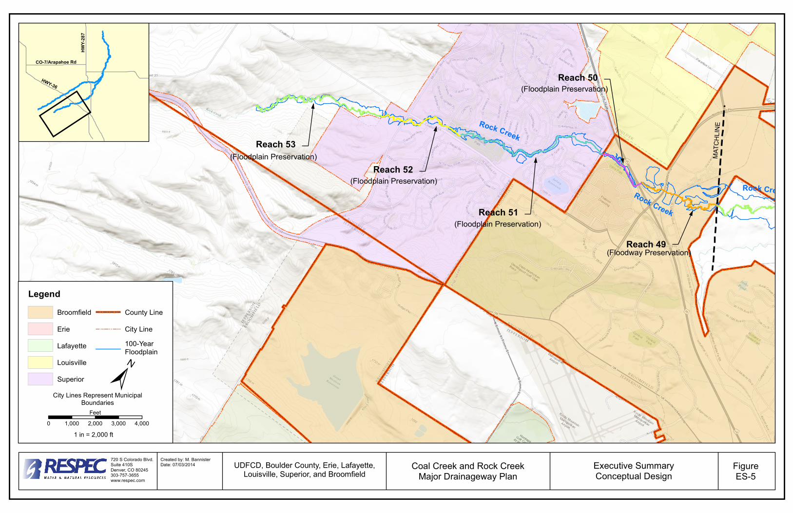
Reach 49(Floodway Preservation)
Reach 50(Floodplain Preservation)
Reach 51
(Floodplain Preservation)Reach 52
(Floodplain Preservation)
Reach 53(Floodplain Preservation)
Rock Creek
Coal Creek
Coal CreekCoal Creek
Rock Creek
Rock Creek
MATC
HLIN
E
720 S Colorado Blvd.Suite 410SDenver, CO 80245303-757-3655www.respec.com
Created by: M. BannisterDate: 07/03/2014 Executive Summary
Conceptual DesignFigureES-5
Coal Creek and Rock CreekMajor Drainageway Plan
UDFCD, Boulder County, Erie, Lafayette,Louisville, Superior, and Broomfield
HWY-2
87HWY-36
CO-7/Arapahoe Rd
0 1,000 2,000 3,000 4,000Feet
1 in = 2,000 ft
City Lines Represent Municipal Boundaries
LegendBroomfieldErieLafayetteLouisvilleSuperior
County LineCity Line100-YearFloodplain
0 1,000 2,000 3,000 4,000Feet
1 in = 2,000 ft