cnp brochure - rodelta · 100 50 50 65 80 100 125 125 100 125 125 150 200 200 4 5 7 9 del 20 25 32...
TRANSCRIPT


Chemical Process Industries, Petro Chemical,
Nuclear, Refinery, Paper and Power Plants etc.
Pumps suitable for handling Corrosive Acids,
Alkalies, Salt Solutions, Caustics, Hydro Carbons,
Oils, Thermic Fluids, Liquefied Gases, Condensates,
Viscous Liquids etc.
RANGE APPLICATIONS
Delivery size : up to 200 mm
3Capacity : up to 900 m /hr
Head : up to 225 metres
Working : 16-30 kg/cm2
Pressures
Temperature : (-)50ºC to +350ºC
Casing
Impeller
Shaft
Gland
Bearing Bracket
Support Foot

Pumps are as per EN 22858 (DIN 24256) and ISO 2858. The design is of back pull out type. Large variety of
models are available to operate at 1450 rpm and 2900 rpm at 50Hz.
Casing :
The casing has axial suction and top centre line delivery. Smooth hydraulic passages ensure high efficiency. Normal design is for foot mounted pumps. Centre line mounting for special applications are also available.
Impeller :
The impellers are of enclosed type and semi-open impellers can also be supplied. Hydraulic balancing of impellers is achieved either by back vanes or by balancing holes. The impellers are statically and dynamically balanced. Reliable fixing of the impeller on shaft is achieved by using helicoil insert under impeller nut. To improve NPSH performance, inducer can be supplied.
Shaft :
The shaft is supported by two antifriction bearings to take residual axial thrust and prevent axial float or radial run out. It is fully protected from the liquid handled by means of a shaft sleeve and gaskets between impeller nut, impeller hub and shaft sleeve.
Stuffing Box :
The stuffing box is sealed by gland packing or by cartridge type mechanical seal. Conversion from gland packing to mechanical seal is achieved by changing some standardised parts. Re-machining of stuffing box is not necessary. Stuffing box cooling is provided for operating temperature 105°C for gland packed and 140°C for mechanical seal fitted pumps.
Bearing :
The bearings are oil lubricated. For high temperature (above 180°C) application, bearing oil cooling arrangement is provided. All pumps are provided with reinforced bearing arrangement as standard supply.
Direction of Rotation :
Clockwise viewed from driving end.
Drive :
Pumps can be driven by electric motor or engine.
Flanges :
ANSI B 16.1, CL 125 Flat Face : for CI/BR
ANSI B 16.5, CL 150 Raised Face - for sp.metals viz. st.steel, cast steel etc.
Drilling as per DIN, ASA, BS etc. (Optional)
FEATURES
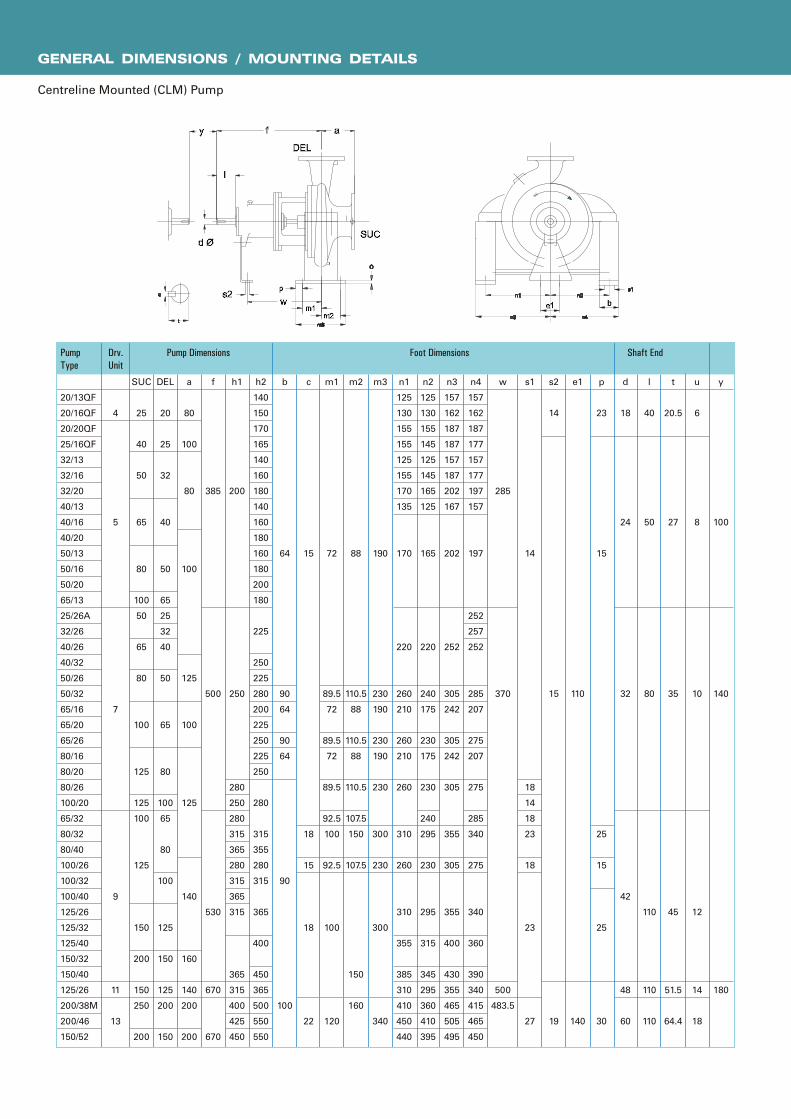
GENERAL DIMENSIONS / MOUNTING DETAILS
Centreline Mounted (CLM) Pump
y
100
140
180
u
6
8
10
12
14
18
t
20.5
27
35
45
51.5
64.4
l
40
50
80
110
110
110
d
18
24
32
42
48
60
p
23
15
25
15
25
30
e1
110
140
s2
14
15
19
s1
14
18
14
18
23
18
23
27
w
285
370
500
483.5
n4
157
162
187
177
157
177
197
157
197
252
257
252
285
207
275
207
275
285
340
275
340
360
390
340
415
465
450
n3
157
162
187
187
157
187
202
167
202
252
305
242
305
242
305
355
305
355
400
430
355
465
505
495
n2
125
130
155
145
125
145
165
125
165
220
240
175
230
175
230
240
295
230
295
315
345
295
360
410
395
n1
125
130
155
155
125
155
170
135
170
220
260
210
260
210
260
310
260
310
355
385
310
410
450
440
m3
190
230
190
230
190
230
300
230
300
340
m2
88
110.5
88
110.5
88
110.5
107.5
150
107.5
150
160
m1
72
89.5
72
89.5
72
89.5
92.5
100
92.5
100
120
c
15
18
15
18
22
b
64
90
64
90
64
90
100
h2
140
150
170
165
140
160
180
140
160
180
160
180
200
180
225
250
225
280
200
225
250
225
250
280
315
355
280
315
365
400
450
365
500
550
550
h1
200
250
280
250
280
315
365
280
315
365
315
365
315
400
425
450
f
385
500
530
670
670
a
80
100
80
100
125
100
125
140
160
140
200
200
20/13QF
20/16QF
20/20QF
25/16QF
32/13
32/16
32/20
40/13
40/16
40/20
50/13
50/16
50/20
65/13
25/26A
32/26
40/26
40/32
50/26
50/32
65/16
65/20
65/26
80/16
80/20
80/26
100/20
65/32
80/32
80/40
100/26
100/32
100/40
125/26
125/32
125/40
150/32
150/40
125/26
200/38M
200/46
150/52
SUC
25
40
50
65
80
100
50
65
80
100
125
125
100
125
150
200
150
250
200
4
5
7
9
11
13
DEL
20
25
32
40
50
65
25
32
40
50
65
80
100
65
80
100
125
150
125
200
150
Pump Dimensions Foot Dimensions Shaft EndDrv.
Unit
Pump
Type
� � �� � �
�� � � � �� � � � � � � �

GENERAL DIMENSIONS / MOUNTING DETAILS
Foot Mounted (FM) Pump
31
38
43
36
44
38
40
47
39
42
48
42
46
53
69
90
90
90
103
90
120
77
79
96
85
86
116
106
140
146
181
134
157
164
158
179
212
260
285
y
100
100
140
140
u
6
8
10
12
t
20.5
27
35
45
l
40
50
80
110
dØ
18
24
32
42
e1
110
110
110
110
s2
14
15
15
15
s1
14
11.5
14
14
18
14
18
18
23
18
23
23
w
285
285
370
370
370
n2
140
160
190
160
212
140
190
160
190
212
190
212
212
250
250
280
250
280
212
250
280
250
280
315
280
315
355
315
400
315
400
450
n1
190
210
240
210
265
190
240
210
240
265
240
265
280
320
320
345
320
345
280
320
360
320
345
400
360
400
435
400
500
400
500
550
m2
50
70
50
70
95
95
95
120
95
120
120
150
120
150
150
m1
80
100
80
100
125
125
125
160
125
160
160
200
160
200
200
c
10
14
10
14
14
16
14
16
16
18
16
18
22
18
b
50
50
65
65
65
80
65
80
80
100
80
100
100
h2
140
150
170
165
180
140
160
180
140
160
180
160
180
200
180
225
225
250
225
280
200
225
250
225
250
280
280
280
315
355
280
315
355
355
355
400
400
450
h1
100
132
160
132
112
132
160
112
132
160
132
160
160
180
180
200
180
225
160
180
200
180
225
200
225
250
280
225
250
280
250
280
315
315
315
f
385
385
500
530
a
80
100
80
100
100
125
125
100
125
125
140
160
160
20/13QF #
20/16QF #
20/20QF #
25/16QF #
25/20QF #
32/13
32/16
32/20
40/13
40/16
40/20
50/13
50/16
50/20
65/13
25/26
32/26
40/26
40/32
50/26
50/32
65/16
65/20
65/26
80/16
80/20
80/26
100/20
65/32
80/32
80/40
100/26
100/32
100/40
125/26
125/32
125/40
150/32
150/40 $
SUC
25
40
50
65
80
100
50
50
65
80
100
125
125
100
125
125
150
200
200
4
5
7
9
DEL
20
25
32
40
50
65
25
32
40
50
65
80
100
65
80
100
125
150
150
Pump Dimensions Foot Dimensions Shaft EndDrg.
Unit
Pump
Type
Wt.
Kg.
l
SUC
DEL
m2crs
wcrs
s2
dØ
ay f
m1crs
s1 e1
c
b
h2
h1
n2
n1
All dimensions are in mm

GENERAL OUTLINE DIMENSIONS
l
SUC
DEL
m2crs
wcrs
s2
dØ
ay f
m1crs
s1e1
c
b
h2
h1
n2
n1
t
u
Note :
# These pumps provided with semi open impeller only.
$ These pumps cannot be supplied with semi open impeller.
125/45 $
150/43 $
65/43 $
11A
11B
9
SUC
150
200
100
Del
125
150
65
a
160
160
160
f
670
685
530
h1
350
350
280
h2
450
475
365
b
100
100
80
c
20
20
18
m1
180
180
160
m2
120
120
120
m3
70
90
60
n1
550
550
435
n2
450
450
355
w
500
514
370
s1
23
23
18
s2
19
19
15
e1
140
140
110
Pump Dimensions Foot Dimensions
d*
48
48
42
l
110
110
110
t
51.4
51.4
45
u
14
14
12
y
180
180
140
Shaft End
290
300
195
Wt.Kg.
DrivingUnit
PumpSize
100/16
125/20
125/26
150/26
150/52 $
200/38M $
200/46 $
80/40DV
100/40DV
7
9
11
9
13
11
11
DEL
100
125
125
150
150
200
200
80
100
SUC
125
125
150
200
200
250
250
125
150
a
150
140
140
160
200
200
200
125
140
f
500
530
670
530
670
670
670
670
670
h1
225
250
280
280
400
400
425
280
280
h2
280
315
355
375
550
500
550
355
355
b
65
80
80
100
150
120
120
80
100
m1
125
160
160
200
240
240
240
160
200
m2
95
120
120
150
180
180
180
120
150
w
370
370
500
370
483
483.5
483.5
500
500
s1
14
18
18
23
27
27
27
18
23
s2
15
15
19
15
19
19
19
19
19
e1
110
110
140
110
140
140
140
140
140
dØ
32
42
48
42
60
60
60
48
48
l
80
110
110
110
110
110
110
110
110
t
35
45
51.5
45
64.4
64.4
64.4
51.5
51.5
u
10
12
14
12
18
18
18
14
14
y
140
140
140
140
180
180
180
180
180
97
138
190
175
435
550
560
177
200
c
14
16
16
20
30
30
30
16
18
n1
320
400
400
500
650
550
640
435
500
n2
250
315
315
400
530
430
540
355
400
Pump Dimensions Foot Dimensions Shaft End Wt.Kg.
DrivingUnit
PumpSize
m3
u
t
11C
SUC
200
Del
200
a
200
F
720
H1
370
h2
315
b
100
c
25
m1
335
m2
265
n1
630
n2
560
w
650
s1
27
s2
19
e1
140
Pump Dimensions Foot Dimensions
Ød4
48
l
110
t
51.4
u
14
y
180
Shaft End
280
Wt.Kg.
DrivingUnit
200 / 33
PumpSize
B
265
� � � � � � � � � � � � � � � � � � �

CROSS-SECTIONAL VIEW
INTERCHANGEABILITY OF COMPONENTS
5
7
9
11
11
11
11/A
11/B
11/C
13
Pump Unit
32/13
40/13
50/13
65/13
32/16
32/16A
40/16
50/16
50/16A
32/20
32/20A
40/20
40/20A
50/20
65/16
80/16
65/20
80/20
100/20
25/26
32/26
40/26
50/26
65/26
65/26N
80/26
40/32
50/32
100/16
100/26
125/26
65/32 (1450 rpm)
65/32 (2900 rpm)
80/32
100/32
125/32
150/32
150/32N
80/40
80/40N
100/40
125/40
125/40N
125/20
150/26
150/40
65/43
80/40DV
125/26 (2900 rpm)
100/40DV
125/45
150/43
200/33
150/52
200/38M
200/46
Size
1
2
3
4
5
6
7
8
9
10
11
12
13
14
15
16
17
18
19
20
21
22
23
24
25
26
27
28
29
30
Casing
1
2
3
4
5
6
7
8
9
10
11
12
13
14
15
16
17
18
19
20
21
22
23
24
25
26
27
28
29
30
31
32
33
34
35
36
37
38
39
40
41
42
43
46
47
44
45
48
31
41
50
51
49
52
53
54
Impeller
1
2
3
2
2
3
4
5
4
5
4
6
7
8
9
10
11
12
13
14
Casing Cover
1
2
3
4
5
6
7
8
Bearing Housing & Shaft
31
32
33
34
35
36
37
40
41
38
39
42
29
43
44
45
46
47
48
49
15
16
17
20
20
21
18
19
17
17
21
22
23
24
25
26

GENERAL OUTLINE DIMENSIONS
INTERCHANGEABILITY OF COMPONENTS
Pump Unit Size Casing Impeller Casing Cover Bearing Housing& Shaft
20/13
20/16
20/20
32/13
40/13
50/13
65/13
25/16
32/16
40/16
50/16
32/20
40/20
50/20
65/16
80/16
65/20
80/20
100/20
32/26
40/26
50/26
65/26
80/26
40/32
50/32
100/26
125/26
65/32
80/32
100/32
125/32
150/32
80/40
100/40
125/40
4
5
7
9
1
2
3
4
5
6
7
8
9
10
11
12
13
14
15
16
17
18
19
20
21
22
23
24
25
26
27
28
29
30
31
32
33
34
35
36
1
2
3
4
5
6
7
8
9
10
11
12
13
14
15
16
17
18
19
20
21
22
23
24
25
26
27
28
29
30
31
32
33
34
35
36
1
2
3
4
5
6
7
8
9
10
11
12
13
14
15
16
17
18
19
20
21
22
1
2
3
4

BACK PULL OUT ARRANGEMENT WORKING TEMPERATURE AND PRESSURE
Using spacer type coupling, back-pullout design
enables the pump rotating unit to be removed
without disturbing the pipe connections. The prime
mover is also undisturbed. This reduces servicing
time, resulting in lower maintenance costs and
reduction in production losses.
Note :
The pressure and temperature data
holds good only if flanges are
suitable to a particular operating
pressure and temperature.
CAST ST & ST.STEEL.
S.G.IRON
C.I. & BRONZE
ALTERNATIVES AVAILABLE
Bearing Oil Cooling Arrangement
For high temperature applications above 180°C
bearing oil cooling arrangement is provided.
Centre line Mounting
For high temperature applications between 180°C
and 350°C, pumps are offered with centreline
mounting.
Steam Jacket Arrangement
This special design can be offered for handling
liquids that cannot be pumped when cold. Except
for pump casing, casing cover and gland, all parts
are of standard design.
Cooling Water Inlet
Cooling Water Outlet
Steam Jacket Arrangement
-100 Cº 0ºC 100 Cº 200 Cº 300 Cº 350 Cº
30
20
10
PR
ES
SU
RE
kg
/cm
^2
Temp ºC-50 Cº
-40ºC
-30 Cº

MATERIAL STANDARDS - GENERAL INFORMATION
Casing / Casing Cover Cast Iron / Cast Steel / Stainless Steel / Duplex Steel
Impeller Cast Iron / Bronze / Cast Steel / Stainless Steel / Chrome Steel / Duplex Steel
Wear Ring / Wear Plate Cast Iron / Bronze / Steel
Shaft Carbon Steel / Stainless Steel / Duplex Steel
Shaft Sleeve Stainless Steel / Bronze
Cast Iron
Cast Iron IS 210 Gr. FG 260 ASTM A48 Class 40 (0.6025)DIN 1691 GG25
Spheroidal Graphite Cast Iron
SG Iron (Ductile Iron) IS 1865 Gr 400/15 A536, 60-40-18 (0.7040)DIN1693 GGG40
SG Iron (Ductile Iron) IS 1865 Gr 500/7 A536, 65-45-12 (0.7050)DIN1693 GGG50
Carbon Steel
Carbon steel (Wrought) IS 1570 (part II) Gr. 40C8 ASTM A107 Gr. 1040 (1.1186)C40E/CK40
Carbon steel (Wrought) IS 1570 (part II) Gr. 20C8 ASTM A107 Gr. 1020 (1.0402)C22
MS Steel MS IS 2062 - Fe 410 W A ASTM-A283 GR.D DIN 1700 GR ST4-2FABRICATED STEEL44
Cast Steel Grades
Cast Steel ASTMA 216 Gr. WCB 1.0619(GS-C25)
Cast Stainless Steel
Stainless Steel CF8M IS 3444 Gr. 4 ASTMA 351 Gr. CF8M 1.4408(GX5CrNiMo19-11-2)
Stainless Steel CF8M IS 3444 Gr. 4 ASTMA 743 Gr. CF8M 1.4408(GX5CrNiMo19-11-2)
Stainless Steel CF3M IS 3444 Gr. 16 ASTMA 351 Gr. CF3M 1.4409(GX2CrNiMo19-11-2)
Stainless Steel CF3M IS 3444 Gr. 16 ASTMA 743 Gr. CF3M 1.4409(GX2CrNiMo19-11-2)
Stainless Steel CF8 IS 3444 Gr. 1 ASTMA 351 Gr. CF8 1.4301(X5CrNi18-10)
Stainless Steel CF3 IS 3444 Gr. 15 ASTMA 351 Gr. CF3 1.4306(X2CrNi19 11)
Cast Chromium Stainless Steel
Stainless Steel CA15 IS 3444 Gr. 10 ASTMA 217 Gr. CA15 1.4106&1.448(DIN17445 GX12Cr14)
Stainless Steel CA15 IS 3444 Gr. 10 ASTMA 743 Gr. CA15 1.4106&1.448(DIN17445 GX12Cr14)
Stainless Steel CA6NM IS 3444 Gr. 24 ASTMA 487 Gr. CA6NM 1.4313&1.4317(GX5CrNiMo13-4)
Stainless Steel CA6NM IS 3444 Gr. 24 ASTMA 743 Gr. CA6NM 1.4313&1.4317(GX5CrNiMo13-4)
Chromium Stainless Steel Round Bar Material
Stainless Steel 410 IS 1570 (part V) Gr. X12Cr12 ASTMA 276 type 410 1.4006(X10Cr13)
Stainless Steel 420 IS 1570 (part V) Gr. X20Cr13 ASTMA 276 type 420 1.4021(X20Cr13)
Stainless Steel 431 IS 1570 (part V) Gr. X15Cr16Ni2 ASTMA 276 type 431 1.4057(X20CrNi17)
Stainless Steel 316 IS 1570 (part V) Gr. X04Cr17Ni12Mo2 ASTMA 276 type 316 1.4401(X5CrNiMo17122)
Stainless Steel 316L IS 1570 (part V) Gr. X02Cr17Ni12Mo2 ASTMA 276 type316L 1.4404(X2CrNiMo1810)
Cast Duplex Steel
Duplex Steel 1A ASTMA 890 Gr. CD4MCu 25Cr-5Ni-Mo-Cu
Duplex Steel 2A ASTMA 890 Gr. CE8MN 24Cr-10Ni-Mo-N
Duplex Steel 3A ASTMA 890 Gr. CD6MN 25Cr-5Ni-Mo-N
Super Duplex steel 4A ASTMA 890 Gr. CD3MN 25Cr-7Ni-Mo-N
Super Duplex steel 5A ASTMA 890 Gr. CE3MN 24Cr-10Ni-Mo-N
Non Ferious Materials
Bronze IS 318 Gr. LTB2 (CuSn5Zn5Pb5C) ASTMB 584 - C90500 DIN 1705 Rg 5
Phosphor Bronze IS 28 Gr. 1 (CuSn11PC)
Zinc Free Bornze IS 28 Gr. 1 (CuSn10C)
Material Type Indian Standard (IS) American Standard (ASTM) DIN
MATERIALS
MATERIAL OF CONSTRUCTION

2
3
6
4
5
7
10
20
60
40
30
50
100
70
543 6 10 3020 40 60 100 300200 400 800
600 1000500
FAMILY CURVES
3Discharge in (m /hr)
Tota
l H
ead
in
(m
)
18
12
10
1514
16
20
30
40
100
70
50
60
90
80
160
140
120
180
150
200
300
500105 703020 40
6050
20080100 150 300 4003 4 600
700
200/46
150/40
20
0/3
8M
150/52
200/33
100/40
32/26
100/20
100/26
65/16
80/16
50/26
80/26
80/20
65/26
125/26
150/32N
40/3265/3250/32
80/40N
125/40N
125/32
150/32
125/40
80/32
100/16
150/26
80/40
40/26
125/20
150/43
40/13
40/16
40/2050/20
50/16
50/13
65/13
65/20
65/26N
65/43
125/45
100/32
32/13
32/16
32/20
25/26A
50/13 65/13
32/13
100/32
40/13
80/26
125/26
80/40DV
100/40DV
125/20
65/16
40/16
100/1632/16
50/16
80/2050/20
40/20
50/26
32/20
50/32
65/20
65/26N
80/3265/32
100/20
40/32
32/26
25/26A
100/26
65/26
40/26
80/16
Tota
l H
ead
in
(m
)
3Discharge in (m /hr)
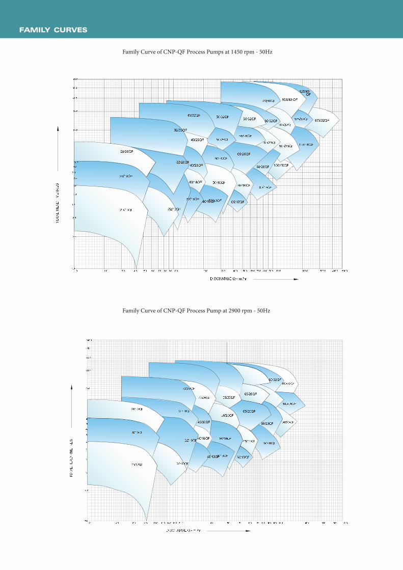
FAMILY CURVES
! " # $ " # % " # & " # ' " # ( " # ) " # * " # + # " # ! # " # $ # " # % # " # & # " # ' # " # ( # " # ) # " # * # " # + # # " # ! # # " # $ # # " # % # # " #+ " # & # # " #+ " # , - . / 0 1 2 3 4 5 6 7 8 9 :;! " #< = > ? = @ A< = > ? B @ A< = > C ? @ A
D = > E C @ AD = > E B @ A< = > E B @ AC ? > E C @ A < = > E C @ AC ? > E B @ AE = = > ? B @ AE = = > C ? @ A E ? D > C ? @ AE = = > < = @ A
E ? D > ? B @ AE ? D > < =
E = = > ? = @ AE D = > C ? @ AD = > ? = @ AD = > ? B @ AD = > C ? @ A
B D > E C @ AB D > E B @ AB D > ? = @ AB D > ? B @ AF = > E B @ AF = > ? = @ A
F = > C ? @ AF = > < = @ AF = > ? B @ A
' # " #
? = > E C @ AGHGIJKLIM NOLGPLQ $ " #% " #C ? > ? = @ A? = > ? = @ A C ? > ? B @ A
) " #* " #+ # " #! # " #$ # " #% # " #& # " #? = > E B @ A& " #' " #( " #
B D > C ? @ A @ A
R S T U S T V S T W T S T W X S T W R S T W U S T W V X T R T U T V T W T T W X T W R T W U T W V T X T T R T T U T T V T TX S T W T T TV S TW X S TW U S TX T S TX R S TX V S TY X S TY U S TV T S TR T S TW X T S TW U T S TX T T S TX R T S T
R S TZ [ \ ] [ ^ _Z [ \ ] ` ^ _Z [ \ a ] ^ _
b [ \ c a ^ _b [ \ c ` ^ _] [ \ c a ^ _] [ \ c ` ^ _ Z [ \ c a ^ _a ] \ ] [ ^ _a ] \ ] ` ^ _] [ \ ] [ ^ _ c [ [ \ ] ` ^ _c [ [ \ a ] ^ _c [ [ \ ] [ ^ _b [ \ ] [ ^ _b [ \ ] ` ^ _b [ \ a ] ^ _
` b \ c a ^ _` b \ c ` ^ _` b \ ] [ ^ _` b \ a ] ^ _` b \ ] ` ^ _d [ \ c ` ^ _d [ \ ] [ ^ _
d [ \ a ] ^ _d [ \ ] ` ^ _
e f g h i j k l m n o p q r stutvwxyvz {|yt}y~
�a ] \ c a ^ _a ] \ c ` ^ _ Z [ \ c ` ^ _