cnc compact machinery - isel
TRANSCRIPT
isel Germany AG Bürgermeister-Ebert-Straße 40 D-36124 Eichenzell Tel.: (06659) 981-0 Fax: -776
Operating Instruction
CNC compact machinery
type model
ICP iMC-P ICP 3020, ICP 4030

ICP 3020 / ICP 4030 iMC-P
Seite 1
About this manual Used shortcuts MD Machinery directive 2006/42/EC Used symbols You will find different symbols in this manual that signalizes important information/ facts and danger.
Warning! This symbol indicates dangers that cause damages for person’s health, physical injury or death.
Warning! Dangerous voltage! Warning of danger from electricity. Ignoring can lead to serious injury or death.
Attention! This Symbol indicates important notes. Ignoring this symbol leads to damages and malfunctions of the machinery
Information: This symbol indicates important information and notes.
Observe the safety instructions
Before you take the CNC machine ICP in operation, working with the machine or make additions or changes to the wiring of the machine / in the housing of the machine, make sure to read carefully the safety instructions in this manual. (Chapter Fehler! Verweisquelle konnte nicht gefunden werden.).

ICP 3020 / ICP 4030 iMC-P Operating instruction
Seite 2
Copyright isel Germany AG, 2009 All rights reserved. Despite all care, printing errors and mistakes cannot be excluded. For suggestions and information on errors, we are grateful. CE mark for (completed) CNC machinery: isel CNC machinery are CE compliant and marked accordingly.
For these machines is the CE declaration of conformity valid. No CE mark for partly completed machinery: Partly completed machinery (definition from EC machinery directive 2006/42/EC) has no CE mark. For partly completed machinery the declaration of incorporation (referred to in Annex II, part 1, section B) is valid. For all other machinery parts and components, be applied to the CE safety directives, initial operation are prohibited until all appropriate requirements are met.
The company isel Germany AG assumes no responsibility or liability if you make any
changes without the consent of the manufacturer of the machine that affect the CE-conformity of the machine. The EMC test is valid only for the controller’s original configuration ex works, i.e. the delivery state.
Manufacturer: isel Germany AG
Bürgermeister-Ebert-Straße 40 D-36124 Eichenzell
Tel: (06659) 981-700 Fax: (06659) 981-776 e-mail: [email protected] http://www.isel-germany.com
Item-no.: 970280 BE016 (translation of operation instruction in German language)
State: 09/2010 Technical changes reserved.
Latest operating instructions and manuals for download, visit: www.isel-data.de/manuals

ICP 3020 / ICP 4030 iMC-P Operating instruction
Seite 3
Table of contents
1 Introduction ................................................................................................................... 5
2 Intended use and reasonably foreseeable misuse .................................................... 6
3 Safety instructions ........................................................................................................ 8
3.1 Occupational safety ...................................................................................... 9
3.2 Operators ..................................................................................................... 9
4 Delivery status from the factory (quality safety) ...................................................... 10
5 Installation and connection of the CNC machine ..................................................... 11
5.1 Dimensions and space requirement ........................................................... 11
5.2 Transport of the CNC machine ................................................................... 12
5.3 Installation of the CNC machine ................................................................. 12
5.4 Coordinate system and reference point ...................................................... 13
5.5 Tooling machine ......................................................................................... 13
5.5.1 Enclosure with safety interlock 14
6 Assembly and operation ............................................................................................ 15
6.1 Safety notes................................................................................................ 15
6.2 Overview .................................................................................................... 16
6.3 Connectors ................................................................................................. 17
6.3.1 Connectors on the back side of the machine 17
6.3.2 Control elements on front side of the machine 18
6.3.3 Stepper motor control assembly 19
6.4 Connectors of the stepper motor control .................................................... 20
6.4.1 Access to stepper motor control and their components 20
6.4.2 Connectors 21
6.5 Adjusting the stepper motor power amplifiers ............................................. 26
7 Installation and initial operation ................................................................................ 29
7.1 Safety notes................................................................................................ 29
7.2 Preparation ................................................................................................. 29
7.2.1 Connections 29
7.3 Software installation ................................................................................... 30
7.4 Operation modes ........................................................................................ 31

ICP 3020 / ICP 4030 iMC-P Operating instruction
Seite 4
7.4.1 Using the ICP 3020 / ICP 4030 in CNC mode 31
7.4.3 Using the ICP 3020 / 4030 in DNC mode 33
8 Maintenance ................................................................................................................ 34
8.1 Cleaning the machine ................................................................................. 34
8.2 Lubrication .................................................................................................. 34
9 Faults ........................................................................................................................... 36
10 Accessories .............................................................................................................. 37
11 Technical data .......................................................................................................... 38
11.1 Dimensions and weight .............................................................................. 38
11.2 Drive ........................................................................................................... 38
11.3 Electrical data ............................................................................................. 38
12 Declaration of conformity for complete machinery ............................................... 39
13 Bibliography ............................................................................................................. 40
14 Index .......................................................................................................................... 41
15 Appendix ................................................................................................................... 42

ICP 3020 / ICP 4030 iMC-P Operating instruction
page 5
1 Introduction This manual contains the operation instruction for machinery of type ICP with iMC-P stepper motor control. The machine is delivered fully assembled on a pallet. In the scope of delivery of the ICP 3020 / 4030 is included:
machine case inclusive: o three drive axles with ball screw spindle 16 x 10mm, 5mm, 4mm or 2,5mm,
2 phase stepper motors with two limit switches o protection hood with solenoid interlock
stepper motor control behind the backplane of the machine inclusive:
o net input filter with main switch and fuses o 2 phase stepper motor power amplifiers up to 4 axes with 4A rated current o base board with processor (core module) o security circuit module (SC module) o 48V and 24V power supply unit o Function keys and emergency stop switch on the machine front side o net cable
o communication cable
drilling / milling machine with 3 mm collet
wrench for collet, wrench opening 22
clamping set (lever, stop rails, 5 mm hexagon wrench)
triangular wrench to unlock the protection hood
4-fold power strip with lighted main switch
Remote as control software (optional: ProNC)
CAD/CAM software isyCAD/CAM 2.5 Plus (optional)
operating instruction
Please note this manual that you • install and do commissioning of CNC machine correctly • can work safety, fast and effectively • keep away danger from persons and the equipment • can fully profit from the capabilities of CNC machine.

ICP 3020 / ICP 4030 iMC-P Operating instruction
page 6
2 Intended use and reasonably foreseeable misuse Isel CNC machinery of type ICP are CNC controlled machinery with more than one linear axis resp. one or two optional rotation axis. The motor power amplifiers will be driven via a PC based stepper-motor-control. All control and power electronics for the axis is mounted in a control cabinet.
Differences between CNC machine and CNC base machine:
isel-CNC-machine: In the new, at 29.12.2009 legally binding machine directive 2006/42/EC, is the term “machinery” defined as follows (quote from EC directive, article 2, letter a):
„machinery“ an assembly, fitted with or intended to be fitted with a drive system other than directly applied human or animal effort, consisting of linked parts or components, at least one of which moves, and which are joined together for a specific application.
Each isel-CNC-machine delivered with a tool (e.g. milling or engraving spindle, metering device, measuring device like CCD camera or triangulation laser, water jet nozzle, plasma burner), is for the purpose of the directive 2006/42/EC a machine, because she was manufactured for a specific purpose resp. specific application and therewith a specific usage.
The usage results from the kind of tool which is mounted on a moveable axis, e.g.:
tool = milling tool usage for milling, drilling tool = engraving tool usage for engraving tool = metering device usage for metering tool = water jet nozzle usage for water jet cutting
The manufacturer isel Germany AG is able to effect a legal prescribed risk assessment for the CNC-machines. CNC-machines will be delivered with a machinery enclosure. isel-CNC-base-machine: In the new, at 29.12.2009 legally binding machine directive 2006/42/EC is the term “partly completed machinery” defined as follows (quote from EC directive, article 2, letter g): „partly completed machinery”
An assembly which is almost machinery but which cannot in itself perform a specific application. A drive system is partly completed machinery. Partly completed machinery is only intended to be incorporated into or assembled with other machinery or other partly completed machinery or equipment, thereby forming machinery to which this Directive applies;
Each isel-CNC-base-machine delivered without a tool and therefore not for a specific application is for the purpose of the directive 2006/42/EC a partly completed machine.
The CNC-machine / CNC-base-machine is used for work in dry rooms (workshops, laboratories) and industrial firms (max. ambient temperature: 40°C)

ICP 3020 / ICP 4030 iMC-P Operating instruction
page 7
CNC-machine:
o The CNC-machine (complete machine) is according to the type mounted on the machine tool appropriately used. That is, the concrete tool of the CNC machine specifies the intended use of the machine within the meaning of the Machinery Directive (Annex I, Section 1.1.2). Under this premise, the CNC-machine is suitable for milling, drilling, cutting, engraving, metering, measuring or water jet cutting. The CNC-machine is not suitable for graphite machining.
o Appropriate processing materials are light metals, plastics, wood, glass, platinum materials, etc.
o Not permitted are materials which produces during processing harmful gases
o The CNC-machine is prepared for an extraction unit device. This extraction unit is preferably suitable for dry dust (wood dust, fibreglass / fibreglass dust, platinum dust, etc.).
The CNC base machine (partly completed machine) can be added by you as the buyer of the base-machine with a variety of appropriate processing tools to a CNC-machine (complete machine) in compliance with the requirements of the machinery directive. You are responsible for CE certification if you use the machine itself resp. sell (bring to market). The CE certification also includes the legally required identification of a safe machine by the CE mark.
CNC-machinery for milling processes:
o The CNC-milling-machines are designed for milling/drilling of the following materials: aluminium, copper, brass, plastics (e.g. GRP / fibreglass), wood
o The processing of magnesium is prohibited because of fire.
o During the processing of steel / stainless steel only engraving or a processing with low cutting forces is possible.
o It shall not be used milling spindles with a tool holder greater than ISO 25 or HSK 25 (hollow shank taper). The speed of the spindle drive may not be higher than the corresponding processing speed for the material.
o All machines are designed for milling spindles (spindle machining, induction motor) with a maximum of 3 kW drive power.
o Cutters and drills may be used up to a maximum shaft diameter of 12 mm.
o The tools form cutters and conical formers for timber industry may be used up to a maximum cutting diameter of 45mm and a shaft diameter of 12 mm.
The rapid traverse velocity should not exceed the values of 150mm/sec till 200mm/sec depending on the machine size.
The feed rate of the processing tool in the material must be determined technologically and should be smaller than the rapid traverse speed.
For the secure clamping of the tools in the tool holder, the user is responsible.
To the reasonably foreseeable misuse belongs the operation of the machine by two persons. It is prohibited that one person executes a motion of the axis of the CNC machine via software (manual move or program start) or by pressing the START button on the operating console / CNC operation panel and another person is touching into the machines workspace or do work in another way when the safety door is open and an axis movement is going on.
You are not allowed to manipulate the locking of the safety door.

ICP 3020 / ICP 4030 iMC-P Operating instruction
page 8
3 Safety instructions
Do not operate the machine in a potentially explosive atmosphere
The machine is fully enclosed.
The transparent panes (material: polycarbonate) mounted in the machine frame resp. in the door ensure during operation of the machine (setup or working process) protection against moving machine parts as well as eventually thrown work piece fragments from the work area.
The housing protects you from moving tools, reduces the noise level and holds back chips.
The door is locked during operation and cannot be opened (safety solenoid interlock). Please do not change or remove this mechanism.
You are not allowed to put a CE marked CNC machine into operation if the enclosure is not complete, intact or the polycarbonate panes are damaged.
The delivered CNC base machinery without safety door / hood are partly completed machinery for the purpose of the directive 2006/42/EC. They are delivered without a CE marking. It applies the declaration of incorporation and the assembly instruction.
As the operator of the CNC base machine, you are responsible for taking appropriate protective measures based on your risk assessment to comply the requirements for the machine according to Machinery Directive 2006/42/EC.
During operation of the CNC machine, we recommend the wearing of appropriate hearing protection and appropriate protective equipment (e.g. protective glasses)
Be careful that work pieces are tightly clamped. The use of save and suitable parts / devices for work piece clamping is one of the tasks of the operator of the CNC machine. Unsuitable not safe devices for work piece clamping can cause unfasten of work piece from device during operation. This can result in heavy damage and accidents with fatality or personal damages. In this case can also damages of tool, work piece, clamping device or other parts of the machine occur.
In case of emergency, you will find an emergency HALT switch on your hand control unit / CNC control panel. It will interrupt power supply for the power electronics (motor power amplifiers) and frequency inverter for main spindle drive (STOP category 0 – interrupt of drives power supply)
The key switch on the hand control unit may be used only by knowledgeable and instructed persons, because in TEST mode there is an increased risk of damage.

ICP 3020 / ICP 4030 iMC-P Operating instruction
page 9
Please keep the replacement key switch under your personal check.
The operator has guarantee sufficient ventilation according accruement of dust or gas, caused by the operation process of working pieces.
If the sound pressure level near the machine should be higher than 70 dB(A) the operator has to wear an applicative ear protection.
The work at and with the machine is only allowed for authorized, knowledgeable and instructed persons. Those persons have to be informed by a special instruction about possibly appearing endangerments (especially residual risk).
Do not use running water for cooling but a spray-cooling system with a spray-fog causing the cooling effect (look accessories). Drop formation and their gathering below the mounting table must be avoided.
3.1 Occupational safety By following the instructions at work may present a risk of persons and / or the device can be prevented.
Not observing these instructions may cause a danger to persons and goods by mechanical or electrical influences or the failure of the device.
Not observing the safety results in the loss of any claims.
3.2 Operators
The machine may be operated and maintained only by authorized, trained and instructed personnel. An instructed person is who was on her teaching duties and the possible risks for improper conduct and, where necessary trained and instructed on the necessary safety equipment and protective measures. Such personnel must have received an instruction about possible dangers. As a staff can judge who is due to his technical training, knowledge and experience and knowledge of the relevant provisions of the delegated work and identify possible dangers. If the staff does not have the necessary knowledge, it must be trained accordingly.
ICP 3020 / ICP 4030 iMC-P Operating instruction
page 10
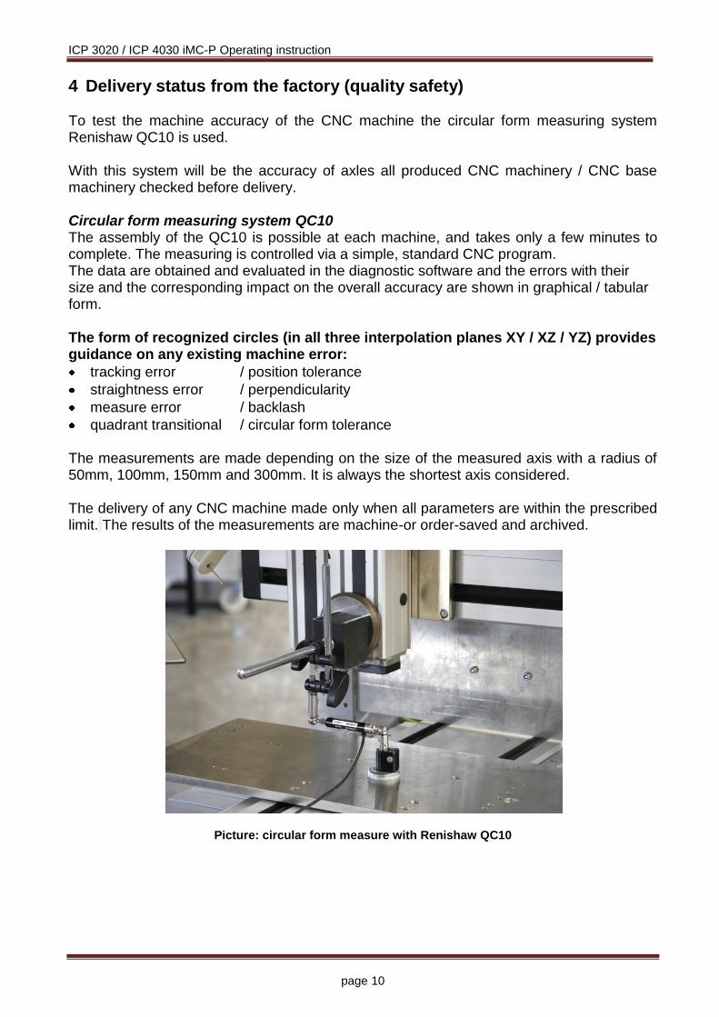
4 Delivery status from the factory (quality safety) To test the machine accuracy of the CNC machine the circular form measuring system Renishaw QC10 is used. With this system will be the accuracy of axles all produced CNC machinery / CNC base machinery checked before delivery. Circular form measuring system QC10 The assembly of the QC10 is possible at each machine, and takes only a few minutes to complete. The measuring is controlled via a simple, standard CNC program. The data are obtained and evaluated in the diagnostic software and the errors with their size and the corresponding impact on the overall accuracy are shown in graphical / tabular form. The form of recognized circles (in all three interpolation planes XY / XZ / YZ) provides guidance on any existing machine error:
tracking error / position tolerance
straightness error / perpendicularity
measure error / backlash
quadrant transitional / circular form tolerance The measurements are made depending on the size of the measured axis with a radius of 50mm, 100mm, 150mm and 300mm. It is always the shortest axis considered. The delivery of any CNC machine made only when all parameters are within the prescribed limit. The results of the measurements are machine-or order-saved and archived.
Picture: circular form measure with Renishaw QC10

ICP 3020 / ICP 4030 iMC-P Operating instruction
page 11
5 Installation and connection of the CNC machine
5.1 Dimensions and space requirement
The space requirement of the machine is limited to the external measurements and to sufficient room in front of the machine in order to operate and arrange the processing, plus approx. 10 cm behind the machine to allow for connectors. The hood of the housing opens upwards. Thus, the required total height is approx. 1,2 meters.
Dimensions and space requirement
Keep the triangular wrench always outside of the machine during transportation.
When planning the floor space for the CNC machine regard the universal access for instructed personnel during a maintenance resp. service phase!

ICP 3020 / ICP 4030 iMC-P Operating instruction
page 12
5.2 Transport of the CNC machine Remove the transport lock from the frame feeds. Use only appropriate lifting equipment (fork lift, trucks, see picture). Lift the machine only from below and do not pull up on the cover. In case of a later transfer, please make sure that the net and connection cables are not damaged.
Unplug the power supply cable before each transport.
Take care during transport that the machine is not suspended to heavy vibrations.
Keep the triangular wrench always outside of the machine during transportation.
5.3 Installation of the CNC machine
The clamping / processing area of the CNC machine and all axes are aligned precisely at right angles from the factory.
Never loosen the fastenings of the axles or the mounting bracket, in which the transverse axis (X-fitted axis). Otherwise, the machine must be re-measured by a technician from manufacturer isel Germany AG.
Place the machine on a plane and solid area. You can compensate the unevenness of the floor / table with the adjustable feet. For precise alignment of the machine you need a spirit level with an accuracy of at least 0.1 mm/m. Save the height of the machine feet with the lock nut.

ICP 3020 / ICP 4030 iMC-P Operating instruction
page 13
5.4 Coordinate system and reference point The coordinate system of the machine is determined as shown in the figure. However, you can select (displace) the P0 work piece zero point freely via software. Ex works, the home position of the machine (machine origin) is defaulted to the back (Y), to the left (X), and to the top (Z). Labels on the machine mark the axes.
5.5 Tooling machine In the collet (4) the standard tooling machine can take tools with a maximum shaft diameter of 6.35 mm (standard 3 mm, other diameters see Accessory). Use two SW 22 open end wrenches for changing the collet. The tooling machine is only enabled by the software. You can manually adjust the rotation speed of the machine using the (1)wheel.
Switch off the main switch of the ICP for dismantling the tooling machine. Remove the electricity cable from the coupler terminal block, loosen the clamping screw and take the tooling machine from the holder. For dismantling the machine with the holder, remove the electricity cable, the two outside screws (3)(loosen only, do not screw very out) and remove the machine with holder and T-slot stones downwards.

ICP 3020 / ICP 4030 iMC-P Operating instruction
page 14
Using corresponding holders, you can also attach many other tools, measuring instruments (laser), or other suitable equipment to the T-slot plate of the Z-axis. Use the branch box at the Z-axis for the electrical connection. If you want to mount the tooling machine or other tools again, you must realign the holder parallel to the XY-plane. The tooling machine is directly wired and switchable by software. Also other optional digital outputs can be used to switch peripheral devices (see technical data). The tooling machine is only useable if the POWER button is lighted, the hood is closed, the tooling machine switch is set set to ON and the software is communicating with the control. 5.5.1 Enclosure with safety interlock
CNC machinery of type ICP have a homogeneous machine frame, e.g. the enclosure is not removable.
The transparent panes (material: polycarbonate) mounted in the machine frame resp. in the door ensure during operation of the machine (setup or working process) protection against moving machine parts as well as eventually thrown work piece fragments from the work area.
You are not allowed to put a CNC marked CNC machine into operation if the enclosure is not complete, intact or the polycarbonate panes ore damaged.

ICP 3020 / ICP 4030 iMC-P Operating instruction
page 15
6 Assembly and operation On delivery: are all control elements to the security circuit of the machine control is the main spindle drive (without speed control 100-230VAC 500 – 750 W or with
speed control 750W ) are depending on customer requests additional actors or sensors
already connected.
6.1 Safety notes
The work on the electrical installation must be performed by authorized and trained personnel. Any changes to the electrical installation will void the warranty and CE conformity. In additions to the machine (e.g. spindle, drives, actuators, sensors, etc.) the operator is responsible for ensuring that all safety rules are followed in accordance with EN 60204-1.
Please not the technical data of the machine as well as the connections.

ICP 3020 / ICP 4030 iMC-P Operating instruction
page 16
safety hood with solenoid interlock
bezel with control elements
working tool (milling machine)
Y-axsi (longitudinal axis)
X-axis (transverse axis)
Z-axis (vertical axis)
safety glass
tool collar Ø 43mm
machine feets (height adjustable)
6.2 Overview

ICP 3020 / ICP 4030 iMC-P Operating instruction
page 17
6.3 Connectors 6.3.1 Connectors on the back side of the machine
number designation description
1 serial interface (RS232)
SubD-9-pin plug
Communication between stepper motor control and control PC is realized via a serial interface (RS232). Use the delivered communication (null modem) cable for connection. A software protocol realizes the faultless transmission of the ASCII characters.
Data transfer parameters:
- 19200 baud - 8 data bits - 1 stop bit - no parity
2 net input module with main switch and fuses
115/230V AC, 50 - 60 Hz net input module with main switch and fuses 2 x 6,3A time-lag
3 ground grounding screw M4

ICP 3020 / ICP 4030 iMC-P Operating instruction
page 18
6.3.2 Control elements on front side of the machine
No notation description
1 emergency stop switch Turns off the power supply for the motor power amplifiers and the working spindle in case of any danger.
2 power-button Use this button to switch on motor power supply voltage for the motor power amplifiers.
3 operation mode switch
(key switch)
Use this switch to choose between automatic- and test-mode. In automatic-mode you can only open the cover or safety door of the machine if no axis is in motion and the mounted working spindle is switched off (means that spindle does not turn).
In the test-mode you can only open the cover or safety door of the machine if the mounted working spindle is switched off (means that spindle does not turn). You can just move the axes at opened cover or safety door if the spindle is switched off.
When switching from the operation mode AUTO onto the operation mode TEST a running working spindle will be immediately switched off. The enable signal for the hood / machine door (COVER button lighted) takes place with a time delay in order to guarantee that the working spindle can run out.
Ensure that in test-mode (key switch on TEST) only authorized personal operates on the machine.
4 start-button
If you press the start button in CNC mode (see chapter: 7.4.1) a saved user program in the flash memory will be executed. You cannot use the start switch in DNC mode.
5 stop-button
If you press the stop button in CNC mode an active user program / axis motion will be stopped. You can continue the execution of the user program by pressing the start button. If you press the stop button in DNC mode an active user program / axis motion will be stopped. To continue the execution of the user program you have to use the controller software (ProNC, Remote).
6 fault-lamp The fault lamp indicates an error within the safety circuit.
7 cover-button
Use this button to open the machines cover or safety door. This is possible only if the conditions from point “4 – operation mode switch“ are complied. An enable for opening of the cover or safety door is signalized by a white lighted cover button.
8 ACK (ACKnowledge) This button has no function on the machine ICP 3020 / ICP 4030.

ICP 3020 / ICP 4030 iMC-P Operating instruction
page 19
6.3.3 Stepper motor control assembly

ICP 3020 / ICP 4030 iMC-P Operating instruction
page 20
6.4 Connectors of the stepper motor control 6.4.1 Access to stepper motor control and their components To get to the connectors of the stepper motor control, you do the following:
Unplug the main power supply plug!
Remove the cover plate of the machine by unscrewing the hex bolts and disconnect the grounding cable from the cover plate. Now you can connect to the terminals of the step motor control additional components (e.g frequency, solenoid valves, sensors, actuators, etc.). Open the housing of the stepper motor Generally it is not necessary to open the case of the stepper motor control.
Opening the housing cover may only be performed by authorized and trained personnel.
After you have removed the cover plate of the machine, remove the housing of the stepper motor control. Loosen the Phillips screws on the top of the housing cover and remove it. Now you get to components such as stepper motor power amplifiers, Sc-module, switching power supplies, etc.

ICP 3020 / ICP 4030 iMC-P Operating instruction
page 21
6.4.2 Connectors
Stepper-Motor – motor connector X-, Y-, Z-, A-axis, Sub-D-9-pin Socket
Connector for motor modules (CNC axis).
Connect / disconnect the Sub-D plug only if the controller is switched off. Ignoring this instruction can lead to damage the motor cable or stepper motor amplifier.
pin description
1 motor phase 1A
2 motor phase 1B
3 motor phase 2A
4 motor phase 2B
5 +24VDC
6 only on Z- axis – motor brake (+24VDC/1,8A output with reference to GND)
7 limit switch 2 (input +24VDC, NC contact)
8 GND
9 limit switch 1 (input +24VDC, NC contact)
The connection of a stepper motor with brake is only on the connector of the Z-axis possible. At this jack the switching signal (+24 V to pin 6) for the motor brake is provided
Remote - security circuit interface, 8-pin socket
Use this connector to include the controller into a higher ranked security circuit system. Please note that the external power input is only useable if the power button from the controller front is switched off. That will be realized by bridging the pins 1 and 2.
pin description
1 power button select
2 power button select
3 external power (make contact)
4 external power (make contact)
5 external emergency stop channel 1 (brake contact, 11)
6 external emergency stop channel 1 (brake contact, 12)
7 external emergency stop channel 2 (brake contact, 21)
8 external emergency stop channel 2 (brake contact, 22)
ICP 3020 / ICP 4030 iMC-P Operating instruction
page 22
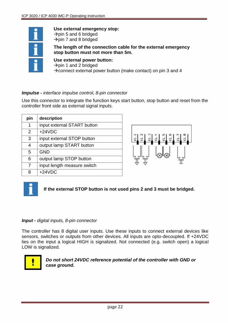
Impulse - interface impulse control, 8-pin connector
Use this connector to integrate the function keys start button, stop button and reset from the controller front side as external signal inputs.
pin description
1 input external START button
2 +24VDC
3 input external STOP button
4 output lamp START button
5 GND
6 output lamp STOP button
7 input length measure switch
8 +24VDC
If the external STOP button is not used pins 2 and 3 must be bridged.
Input - digital inputs, 8-pin connector The controller has 8 digital user inputs. Use these inputs to connect external devices like sensors, switches or outputs from other devices. All inputs are opto-decoupled. If +24VDC lies on the input a logical HIGH is signalized. Not connected (e.g. switch open) a logical LOW is signalized.
Do not short 24VDC reference potential of the controller with GND or case ground.
Use external emergency stop: pin 5 and 6 bridged pin 7 and 8 bridged
The length of the connection cable for the external emergency stop button must not more than 5m.
Use external power button: pin 1 and 2 bridged connect external power button (make contact) on pin 3 and 4

ICP 3020 / ICP 4030 iMC-P Operating instruction
page 23
The binary user inputs 1 – 8 must be wired as shown opposite. The load of the controller internal 24V power supply unit amounts on 1-active state 4 mA per input.
Output - digital outputs, 8-pin connector
The controller has 8 digital user outputs. Use these outputs to connect external devices like relays, or inputs from other devices. The maximum load of each relay output is 24 VDC/300 mA
Do not short 24VDC reference potential of the controller with GND or case ground.
If you have pushed the emergency stop switch all states of the binary user outputs will be maintained and not reset!
The binary user output 1 – output 8 must be wired as shown opposite. The transistor outputs (output 1 – 8) can be rated with 300 mA per output. If all outputs are switched (1-active) the maximum load of the internal 24VDC power supply unit is 1, 5 A (ca. 180mA per output).
ICP 3020 / ICP 4030 iMC-P Operating instruction
page 24
Analog - Out, Sub-D9-pin connector
Use this connector to drive an external frequency inverter with the corresponding working spindle via a 0 – 10 V analog output.
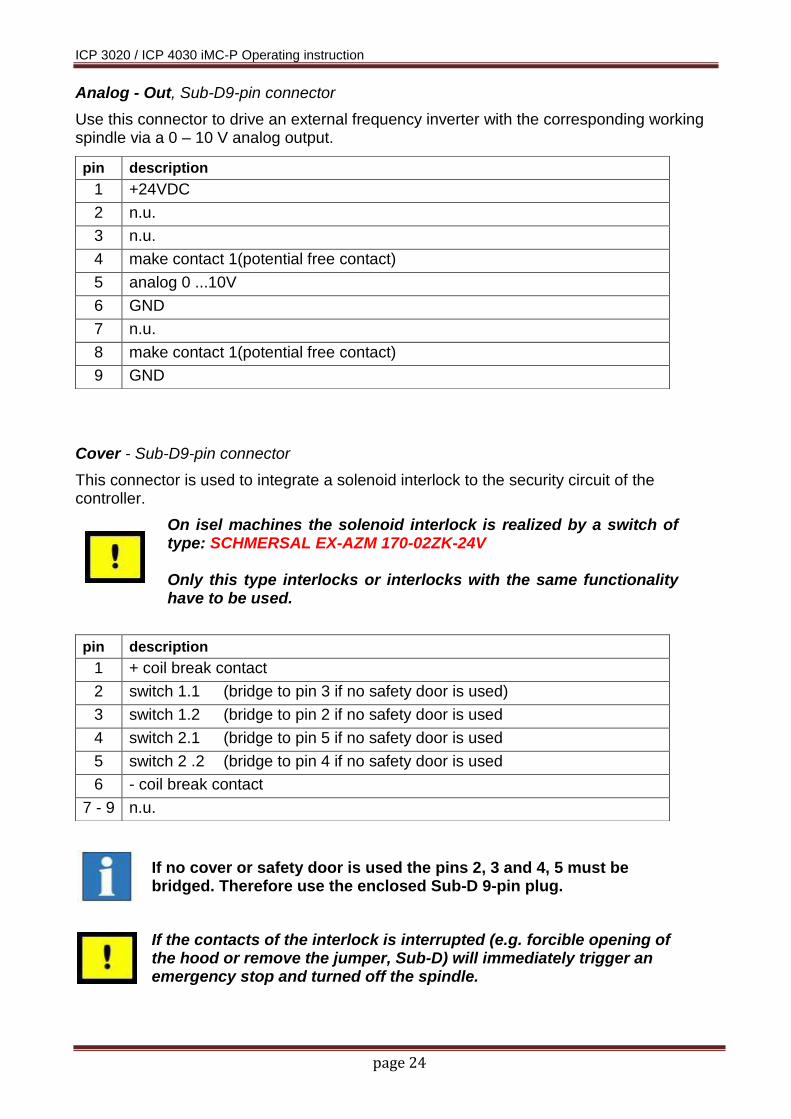
Cover - Sub-D9-pin connector
This connector is used to integrate a solenoid interlock to the security circuit of the controller.
On isel machines the solenoid interlock is realized by a switch of type: SCHMERSAL EX-AZM 170-02ZK-24V Only this type interlocks or interlocks with the same functionality have to be used.
pin description
1 +24VDC
2 n.u.
3 n.u.
4 make contact 1(potential free contact)
5 analog 0 ...10V
6 GND
7 n.u.
8 make contact 1(potential free contact)
9 GND
pin description
1 + coil break contact
2 switch 1.1 (bridge to pin 3 if no safety door is used)
3 switch 1.2 (bridge to pin 2 if no safety door is used
4 switch 2.1 (bridge to pin 5 if no safety door is used
5 switch 2 .2 (bridge to pin 4 if no safety door is used
6 - coil break contact
7 - 9 n.u.
If no cover or safety door is used the pins 2, 3 and 4, 5 must be bridged. Therefore use the enclosed Sub-D 9-pin plug.
If the contacts of the interlock is interrupted (e.g. forcible opening of the hood or remove the jumper, Sub-D) will immediately trigger an emergency stop and turned off the spindle.

ICP 3020 / ICP 4030 iMC-P Operating instruction
page 25
Spindle - 100 - 230V output, three-pin-plug
Use this output connector to directly plug a working spindle or a frequency inverter with a speed controlled working spindle (e.g. iSA750). According to the working spindle type you have to change the internal power supply connection on the security circuit module either for the working spindle without speed control or for the frequency inverter with a working spindle with speed control.
Remove the controller cover by loosen the screws on the right and left side of the controller (only on desk controller type). After that remove the cover plate by loosen the screws all around on the top of the controller case. Connect the 3-pin wire from connector „Spindle 230V“ inside the controller with the for you necessary connector on the security circuit module.
Ex factory the controller is delivered with the connection to X1 (that means for a working spindle without speed control).
Connector X3 for frequency inverter with working spindle and with speed control, max. switching capacity 100-230V / 6A
connector X1 for working spindle without speed control, max. switching capacity 100-230V / 6A
Please note that in case of an emergency stop the power supply voltage on connector X3 will switched off time delayed according to stop category 1. Power supply voltage on connector X 1 will switched off immediately in emergency stop case according to stop category 0.

ICP 3020 / ICP 4030 iMC-P Operating instruction
page 26
Control Elements – connector for control elements, Sub-D-25 pin
Connector for the control elements (buttons, switches) from the front side of the machine.
RS232 (PC) – programming interface Communication between iMC-M / iMC and control PC is realized via a serial interface (RS232). Use the delivered communication (null modem) cable for connection. A software protocol realizes the faultless transmission of the ASCII characters. Therefore it’s necessary that both systems respect the communication protocol:
The connected control PC sends a command which ends with a line end character [CR, char (13)].
The processor unit quits the execution or storing of a command with the quitting signal 0[char (48)] or returns an occurred error with an ASCII character unequal 0.
Data transfer parameters:
- 19200 baud - 8 data bits - 1 stop bit - no parity
6.5 Adjusting the stepper motor power amplifiers The CNC machine ICP 3020/4030 iMC-P has four stepper motor power amplifiers MD24. Settings for rated current, step resolution and current reduction takes place by the DIP-switch on the top side of the amplifiers case. When delivered, all stepper motor drives are set to the corresponding stepper motors of your machine. If it is still necessary that you have to change the settings of the stepper motor power stages (e.g. use of a 4th axis) note the following pages.
Configuration of the controller should be done before first start-up so that a connected motor will not be damaged because of an incorrect power setting.
ICP 3020 / ICP 4030 iMC-P Operating instruction
page 27
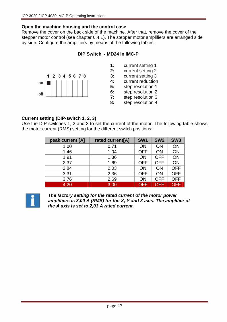
Open the machine housing and the control case Remove the cover on the back side of the machine. After that, remove the cover of the stepper motor control (see chapter 6.4.1). The stepper motor amplifiers are arranged side by side. Configure the amplifiers by means of the following tables:
DIP Switch - MD24 in iMC-P
1: current setting 1 2: current setting 2 3: current setting 3 4: current reduction 5: step resolution 1 6: step resolution 2 7: step resolution 3 8: step resolution 4
Current setting (DIP-switch 1, 2, 3) Use the DIP switches 1, 2 and 3 to set the current of the motor. The following table shows the motor current (RMS) setting for the different switch positions:
peak current [A] rated current[A] SW1 SW2 SW3
1,00 0,71 ON ON ON
1,46 1,04 OFF ON ON
1,91 1,36 ON OFF ON
2,37 1,69 OFF OFF ON
2,84 2,03 ON ON OFF
3,31 2,36 OFF ON OFF
3,76 2,69 ON OFF OFF
4,20 3,00 OFF OFF OFF
The factory setting for the rated current of the motor power amplifiers is 3,00 A (RMS) for the X, Y and Z axis. The amplifier of the A axis is set to 2,03 A rated current.

ICP 3020 / ICP 4030 iMC-P Operating instruction
page 28
current reduction (DIP-switch 4) Use the DIP switch 4 to set the automatic current reduction. If the DIP switch is set to ON the automatic current reduction is deactivated. DIP switch in state OFF means that the current is set to 50% of the motor current if the motor standstill.
DIP 4 current reduction
ON 0% reduction (deactivated)
OFF 50% reduction
If the holding torque is sufficient, the activated automatic current reduction is recommended.
In delivery status the automatical current reduction is activated (DIP 4 = OFF).
Step resolution (DIP-switch 5, 6, 7, 8) Use the DIP switches 5, 6, 7 and 8 to set the step resolution. Setting the factor to a higher value causes a smooth motion of the motor but the maximum reachable velocity will taking down. Also the motor torque will be reduced to 75% in microstep mode. The following table shows the DIP switch settings for the different step resolutions:
micro steps steps/ rev. (1,8 ° motor) SW5 SW6 SW7 SW8
2 400 OFF ON ON ON
4 800 ON OFF ON ON
8 1600 OFF OFF ON ON
16 3200 ON ON OFF ON
32 6400 OFF ON OFF ON
64 12800 ON OFF OFF ON
128 25600 OFF OFF OFF ON
5 1000 ON ON ON OFF
10 2000 OFF ON ON OFF
20 4000 OFF OFF ON OFF
25 5000 OFF OFF ON OFF
40 8000 ON ON OFF OFF
50 10000 OFF ON OFF OFF
100 20000 ON OFF OFF OFF
125 25000 OFF OFF OFF OFF
The Factory set of the step resolution is 800 steps/rev for all motor power amplifiers.

ICP 3020 / ICP 4030 iMC-P Operating instruction
page 29
7 Installation and initial operation
7.1 Safety notes
Please note the technical data of the machine as well as the terminal assignment on chapter Fehler! Verweisquelle konnte nicht gefunden werden..
Ignoring the safety precautions could result in injury to persons and goods by mechanical or electrical influences or the failure of the device.
Ignoring the safety regulations causes the loss of any claims of damage.
7.2 Preparation Before making the connections of the machine be sure that:
- no mechanical defect (loose parts) is identifiable on the machine - all parts and wirings are available - the machine is placed according to the regulations
7.2.1 Connections - connect communication cable (null modem cable) between PC/notebook and machine
- connect main power supply cable
Configuration (if not already preset)
- Remove the backplane of the machine by screwing out the nine hexagon screws. Also remove the earth cable if you taking down the backplane.
- Set the correct motor current and step resolution via the DIP switch on the motor power amplifiers. Information for configuration of the motor power amplifiers you will find in the operating instruction for stepper drive MD24/MD28 /1/.
COM interface on PC / notebook: 9-pin Sub-D (plug)
serial cable Sub-D 9 (socket socket)

ICP 3020 / ICP 4030 iMC-P Operating instruction
page 30
First initial operation
Do the following steps to set up the machine:
Switch on the machine via the main power supply switch on the back side of the machine
Check if emergency stop switch is pulled out and key switch is in position AUTO
To open the hood press the COVER button and push the door short down and after that upwards. The hood can be opened if the COVER button is lighted.
Close the hood and press the POWER ON button to power up the motor amplifiers. The POWER ON button should now be lighted.
Machine is now ready for operation!
Choose the operation mode
- Use the CNC compact machine ICP in CNC or DNC mode (see chapter 7.4)
7.3 Software installation
For operation and programming the machine in CNC mode you need the software PALPC 2.1 on version 2.0.1.04.0 or higher. For operation of the machine in DNC mode you need the control software Remote (optional ProNC) on version 1.46.2.1 or higher with the control interface for IMC4 compatible machine controller. Please note the hints for software installation. You will find them on the delivered installation medium.

ICP 3020 / ICP 4030 iMC-P Operating instruction
page 31
7.4 Operation modes The processors operating system (firmware processor core) provides the following operation modes:
DNC-mode of the control: Computer/Laptop is permanent connected to the stepper motor
controller via serial interface Software Remote(optional: ProNC, Galaad) is used to operate the
machine
CNC-mode of the control: The stepper motor controller of the machine executes user programs
stand alone without a connected PC/Laptop Software PALPC 2.1 is used for programming and download of user
programs into the flash memory of the machines controller
7.4.1 Using the ICP 3020 / ICP 4030 in CNC mode The CNC mode (automatic mode = CNC mode) is the program controlled mode of the stepper motor control of the machine. That means that a user program which is saved in the controller’s memory (flash) will be executed till the end. During the automatic mode (CNC mode) you can stop the execution of the active user program by pressing the STOP-key on the front side of the machine or using the external STOP input of the control. A following operation of the START-key or the activation (1-active) of the external start input effects the resumption of the automatic mode.
Information to operation and programming the CNC compact machine ICP in CNC mode you will find in the PALPC operation manual /2/.
COM interface on PC / notebook: 9-pin Sub-D (plug)
serial cable Sub-D 9 (socket socket)

ICP 3020 / ICP 4030 iMC-P Operating instruction
page 32
PALPC settings and machine test
Control type Select as control type compact control IMC4-M / I-MC-P RS232 settings Select your available COM port an transfer rate 19200 baud Control settings Fill in 800 steps / rev The value for the spindle gradient is depending by the machine type. The max. step frequency is 40KHz (full step).
For a simple test of the machine click on: Transfer Terminal Type into the terminal window the following commands: @0V /request version information
@07 /initialize 3 axis
@0R7 /reference run 3 axis Every command is receipt by a return code (0 …no error)
Please note the factory settings for axis directions and reference directions.

ICP 3020 / ICP 4030 iMC-P Operating instruction
page 33
7.4.3 Using the ICP 3020 / 4030 in DNC mode In DNC mode the stepper motor controller of the machine is connected permanently via RS-232 interface with a control computer (IBM compatible PC or notebook).
A user program stored in flash memory will not be executed. The commands to execute an action/motion (e.g. reference motion, motion of the axis or I/O actions) will be sent by user software from the computer with the new Remote (optional: ProNC) motion control for 4-axis stepper motor controller (IMC4 compatibility mode).
Information to operation and programming the CNC compact machine ICP in CNC mode you will find in the Remote operation manual /3/.
Using digital inputs and outputs and signalization interface in Remote/ProNC
Machinery of type ICP 3020 / ICP 4030 iMC-P have each 8 digital inputs and outputs which can be used by the user.
Important notes !!!
During an axis movement it is not possible to read a digital input by the software because the stepper motor controller has to
send an acknowledgement character before every new command.
During an axis movement it is not possible to set a digital output by the software because the stepper motor controller has to
send an acknowledgement character before every new command.
The signalization (menu: settings signalization) in the Remote (optional ProNC) user interface is used on other isel-controls for integration in higher ranked controls.
Important notes !!!
All configurable inputs and outputs for signalization cannot be used in DNC mode! That means that the controlling via external signals from a higher ranked control (e.g. PLC) is not possible.
COM interface on PC / notebook: 9-pin Sub-D (plug)
serial cable Sub-D 9 (socket socket)
ICP 3020 / ICP 4030 iMC-P Operating instruction
page 34
S
8 Maintenance Open the hood before switching off the machine using the mains switch. After this, this is no more possible.
Switch of the main switch before any cleaning and any maintenance. Also pull the power plug in order to prevent an inadvertent starting.
8.1 Cleaning the machine
- Clean the machine regularly with a broom or vacuum cleaner of all chips (no compressed air). That protects the mechanics against early wear.
- With frequent machining operations and very fine chips (dusts), you should regularly
remove the cover plate of the Y-axis below the T-slot plate and remove possibly penetrated chips and/or dusts.
- The sealing lips include a Teflon component and require no special maintenance.
- Clean the perspex windows with a non-abrasive fluid cleaner.
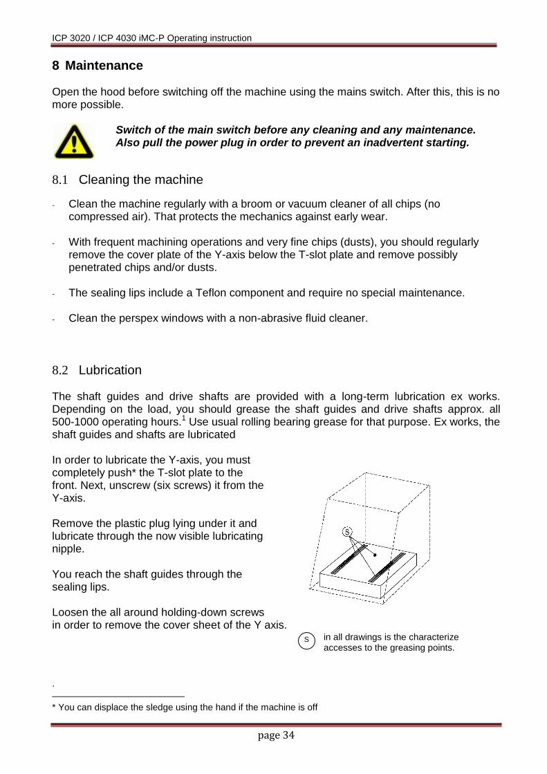
8.2 Lubrication The shaft guides and drive shafts are provided with a long-term lubrication ex works. Depending on the load, you should grease the shaft guides and drive shafts approx. all 500-1000 operating hours.1 Use usual rolling bearing grease for that purpose. Ex works, the shaft guides and shafts are lubricated In order to lubricate the Y-axis, you must completely push* the T-slot plate to the front. Next, unscrew (six screws) it from the Y-axis. Remove the plastic plug lying under it and lubricate through the now visible lubricating nipple. You reach the shaft guides through the sealing lips. Loosen the all around holding-down screws in order to remove the cover sheet of the Y axis.
in all drawings is the characterize accesses to the greasing points.
.
* You can displace the sledge using the hand if the machine is off

ICP 3020 / ICP 4030 iMC-P Operating instruction
page 35
To lubricate the X-axis, move the sledge to the left*. Remove the plastic plug on the left side of the machine and lubricate through the now visible lubricating nipple. You access the shaft guides again through the sealing lips.
At the Z-axis, you must first take the tooling machine from its support. Remove the three plugs and push the sledge completely down*. You can apply some oil onto the shaft guides through the two side holes. The lubricating nipple for the drive is now behind the front opening.

ICP 3020 / ICP 4030 iMC-P Operating instruction
page 36
9 Faults
Error reason solution
machine will not turn on
net input plug not connected
check net input cable connection
main switch not switched on switch on main switch
fuse defect remove net input plug, renew fuse
power supply voltage cannot switch on by POWER button
hood / door is not closed close hood / door
Emergency stop switch is unlocked
unlock Emergency stop switch
software works not correctly
main switch not switched on switch on main switch
power supply for the power amplifiers not switched on
power amplifiers by pressing POWER-button
motor cables not connected check motor cables
no communication via serial interface
incorrect COM port selected select correct COM port
incorrect baud rate select 19200 baud
milling spindle is not working
incorrect setting in the spindle module DLL (only DNC mode)
check settings and change if applicable
switch on the milling spindle (only 100-230 V) is switched OFF
switch on
moving distances of the axles is incorrect
spindle pitch is not correct in the software Remote (in DNC mode)
change spindle pitch in software Remote/6/
spindle pitch is not correct set in the initialize section of user program or in the programming software PALPC (in CNC-mode)
change spindle pitch in the user program or programming software PALPC

ICP 3020 / ICP 4030 iMC-P Operating instruction
page 37
10 Accessories
Matching for each ICP 3020 / 4030 CNC machine, you can order the following accessories:
clamping set (clamp lever SH1,SH2, 2 stop rails, hexagon socket wrench)
additional mounting material for T-groove panel
bench vise 1, 2
additional collet chucks for working spindle
tool kit cutter, driller, graver
three different tool changer (linear, direct or round changer) with high frequency main spindle drive, option: length measurement button
rotation axis(axes)
main spindle drive iSA 500, 750, 900
working spindle UFM 500, UFM 1050
vacuum clamping system isel-Vakufit
pneumatics accessories
cold air cooling isel-CoolMin: cooling unit with cold air nozzle (up to -20°C)
exhaust unit
spray-/cooling unit, cooling medium HL4
work lighting
CAD/CAM software isyCAD/CAM 2.5, Galaad/Lancelot, ProNC /6/
Information for compressed air connection of accessories: To use the optional vacuum clamping system or the tool changer and collets of the working spindle it’s necessary that the location of the machine has a compressed air connection.
accessories air pressure air consumption
pneumatic vacuum pump 4 - 6 bar 100-150 l/min (1 nozzle)
cold air nozzle 3 - 10 bar l/min
cover of the tool changer 3 - 6 bar impulse
milling spindle with automatic tool change > 7.5 bar impulse
on the milling spindle mounted swivel unit for exhaust (specially for woodworking)
2 bar impulse
The necessary software for tool changing inclusive tool length measurement is a part of the control- and programming software Remote / ProNC.
Look at all accessories for a professional installation and note the applicable standards and safety regulations.

ICP 3020 / ICP 4030 iMC-P Operating instruction
page 38
11 Technical data
11.1 Dimensions and weight
data ICP 3020 ICP 4030
dimensions W x D x H [mm] 610 x 650 x 715 780 x 835 x 810
movement area X axis [mm] 300 400
Y axis [mm] 200 300
Z axis [mm] 90 140
axis speeds (X/Y/Z on 10mm spindle gradient) >100/100/80 >100/100/80
pass through height [mm] 115 150
clamping table (WxD) [mm] 250 x 250 600 x 375
T-slot raster [mm] 25 25
approx. weight [kg] 85 150
sound pressure level [db(A)] <75 <75
11.2 Drive
Driving the axles is realized by 2 phase stepper motors:
data ICP 3020 ICP 4030
spindle Ø [mm] 16 16
spindle gradient X axis [mm] 10 10
(standard version) Y axis [mm] 10 10
Z axis [mm] 10 10
motor in standard version (X/Y/Z) [W] 120/120/120 120/120/120
11.3 Electrical data
Net input
net power supply voltage: 100 - 230VAC 50/60 Hz, 16A
fuse: net input 2 x 6,3A / 250V, time-lag
ground: complies with protection class 1
Stepper motor power amplifiers
max. peak current per amplifier: 4,2 A
max. rated current per amplifier: 3,0 A
supply voltage of the power amplifiers: 48 VDC
automatic current reduction: on 50%
Electrical connections
digital inputs: 8 x inputs
digital outputs: 8 x transistor outputs 24VDC/300 mA 1 x relay output 230V/6A
analog output: 1 x analog output 0…10V to drive a main working spindle via frequency inverter
motor brake in Z axis: Yes
Safety
safety category: 2
stop category: 0/1
Working spindle
main spindle: 500W, 11000-25000 U/min, fix wired

ICP 3020 / ICP 4030 iMC-P Operating instruction
page 39
12 Declaration of conformity for complete machinery
EC Declaration of Conformity corresponding Machinery Directive 2006/42/EU, Annex II A
The manufacturer
isel Germany AG Bürgermeister-Ebert-Straße 40 D-36124 Eichenzell
declares hereby, that the following products
Product designation: CNC compact machine ICP
Types: ICP 3020 iMC-P Item-No.: 280210 7406
ICP 4030 iMC-P Item-No.: 280220 7405
conforms to the safety and health requirements of the Machinery Directive 2006/42/EU, Annex I – including those at the time of declaration current alterations..
The following harmonized standards have been applied:
EN ISO 12100-1:2003 Safety of machinery – fundamental terms, general principles of design – Part 1: Basic terminology, methodology
EN ISO 12100-2:2003 Safety of machinery – fundamental terms, general principles of design – Part 2: Technical principles
EN ISO 13857:2008 Safety of machinery – Safety distances to avoid reaching of dangerous regions with upper and lower extremities
EN 349:1993 Safety of machinery – Minimum distances to avoid bruising of parts of the body
EN 953:1997 Safety of machinery – Guards – general requirements for the design and construction of fixed and moveable guards
EN 954-1:1996 Safety of machinery – Safety related parts of control systems, Part 1: General principles for design
EN ISO 13850:2008 Safety of machinery – Emergency-Halt – Design guidelines
EN 14121-1:2007 Safety of machinery – Risk assessment – Part 1: Guidelines
EN 60204-1:2006 Safety of machinery – Electrical equipment of machines, Part 1: General requirements
Also the following EU Directives have been applied
EMC Directive 2004/108/EG
Low Voltage Directive 2006/95/EG
The technical documentation for this machine was created corresponding Annex VII Part A. The manufacturer obligates to provide the technical documentation in electronic mode on demand of authorized governmental agency.
Representative for composition of technical documentation is: Mr. Helmut Danz
Place: Dermbach Date: 18.01.2010
Werner Kister, Managing Board

ICP 3020 / ICP 4030 iMC-P Operating instruction
page 40
13 Bibliography /1/ MD24 MD28 micro stepping driver:
Instruction Manual / hardware description MD24 / MD28 ; isel Germany AG, 01/2010
/2/ PAL-PC: programming instruction: Software manual PALPC; isel automation 06/2004
/3/ Remote: Operation and output program for ISO-, NCP- and CNC files: Software manual Remote; isel-automation 06/2005
Up to date Operating instructions and manuals for download you can find here:
www.isel-data.de/manuals

ICP 3020 / ICP 4030 iMC-P Operating instruction
page 41
14 Index
A
accessories............................................................................ 36 ACK ....................................................................................... 18 air pressure .......................................................................... 36 Analog - Out ......................................................................... 24
C
CE marking .............................................................................. 8 Circular form measuring system .......................................... 10 CNC-mode ............................................................................ 31 Cover .................................................................................... 24 Cover button......................................................................... 18 current setting ..................................................................... 27
D
digital inputs ......................................................................... 37 dimensions ........................................................................... 37 DNC-mode ............................................................................ 31 drive ...................................................................................... 37
E
emergency HALT ..................................................................... 8 Enclosure .............................................................................. 14 external emergency stop ..................................................... 22
F
Fault- lamp............................................................................ 18 Faults .................................................................................... 35
I
instructed persons .................................................................. 9 interface impulse control ...................................................... 22 iSA 36 isel-CoolMin ......................................................................... 36 isel-Vakufit ........................................................................... 36
M
main spindle ......................................................................... 37
movement area .................................................................... 37
N
null modem cable ................................................................. 29
O
Operation mode switch ........................................................ 18 operation modes .................................................................. 31 operators ................................................................................ 9
P
pass through height .............................................................. 37 peak current .......................................................................... 37 processing area ..................................................................... 12
R
rated current ......................................................................... 37 Renishaw QC10 ..................................................................... 10 RS232 .............................................................................. 17, 26
S
safety door .............................................................................. 7 safety interlock ..................................................................... 14 security circuit interface ........................................................ 21 serial cable ............................................................................ 32 serial interface ...................................................................... 17 sound pressure level ............................................................... 9 specific usage ......................................................................... 6 Spindle .................................................................................. 25 start-button .......................................................................... 18 step resolution ............................................................... 28, 29 supply voltage ....................................................................... 37
T
transport ............................................................................... 12
ICP 3020 / ICP 4030 iMC-P Operating instruction
page 42
15 Appendix
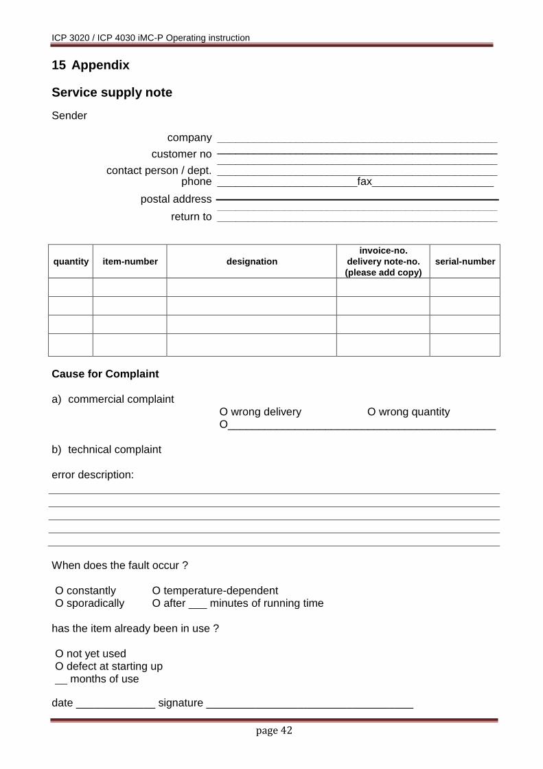
Service supply note Sender
company ______________________________________________
customer no ______________________________________________ ______________________________________________
contact person / dept. ______________________________________________ phone _______________________fax____________________
postal address
______________________________________________ return to ______________________________________________
quantity item-number designation
invoice-no.
delivery note-no.
(please add copy)
serial-number
Cause for Complaint a) commercial complaint
O wrong delivery O wrong quantity O____________________________________________
b) technical complaint error description:
When does the fault occur ? O constantly O temperature-dependent O sporadically O after ___ minutes of running time
has the item already been in use ? O not yet used O defect at starting up __ months of use
date _____________ signature __________________________________

ICP 3020 / ICP 4030 iMC-P Operating instruction
page 43
Please take note in case of returning the product ! 1.) Warrantee proof For the examination of your warranty claim, a copy of the purchase bill or of the receipt is required. We return the product unprocessed against a charge if this proof is missing. 2.) Error description In case of products arriving without precise error description at our facilities (“Defective” or “For Repair” is not sufficient), we have the right to select between carrying out of a liable to pay the costs fault diagnosis or the non-repaired returning against a service charge. 3.) Inadmissible complaints In case of inadmissible complaints (no fault is detectable, probable operator error), the product is self-consciously returned against a service charge.
4.) Wrapping We can only accept returned products in original isel packing or equivalent wrapping. The warranty claim is endangered by missing original or inappropriate wrapping. Resulting transport damages cause the expiration of the warranty claim.
5.) OEM products Products which were not delivered by us are returned in a non-repaired manner against a service charge.
6.) Transport charges isel Germany AG carries the transportation charge for returns from warranty claims. The sender bears all other haulage. Product sent in without paid transportation charges cannot be accepted for organizational reasons.
7.) Sales conditions, delivery conditions and terms of payment As for the rest, the sales conditions, delivery conditions, and terms of payment of isel Germany are valid without change.