cms level-1 trigger review - university of … level-1 trigger review wesley smith, ... 3000 3500...
TRANSCRIPT

W. Smith, U. Wisconsin, CMS Comprehensive Review, Sept. 27, 2004 CMS Level-1 Trigger – 1
CMS Level-1 Trigger ReviewCMS Level-1 Trigger ReviewCMS Level-1 Trigger Review
Wesley Smith,University of Wisconsin,Trigger Project Manager
CMS Comprehensive ReviewSeptember 27, 2004
The pdf file of this talk is available at:http://cmsdoc.cern.ch/cms/TRIDAS/tr/0409/smith_CR_sep04.pdf
See also CMS Level 1 Trigger Home page athttp://cmsdoc.cern.ch/cms/TRIDAS/html/level1.html
W. Smith, U. Wisconsin, CMS Comprehensive Review, Sept. 27, 2004 CMS Level-1 Trigger – 2
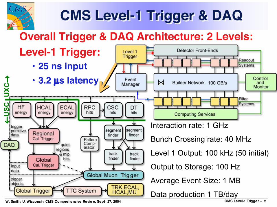
CMS Level-1 Trigger & DAQCMS Level-1 Trigger & DAQCMS Level-1 Trigger & DAQOverall Trigger & DAQ Architecture: 2 Levels:Level-1 Trigger:
• 25 ns input• 3.2 µs latency
Interaction rate: 1 GHz
Bunch Crossing rate: 40 MHz
Level 1 Output: 100 kHz (50 initial)
Output to Storage: 100 Hz
Average Event Size: 1 MB
Data production 1 TB/day
UX
C→
←U
SC
W. Smith, U. Wisconsin, CMS Comprehensive Review, Sept. 27, 2004 CMS Level-1 Trigger – 3
Calorimeter Trig. AlgorithmsCalorimeter Trig. AlgorithmsCalorimeter Trig. Algorithms
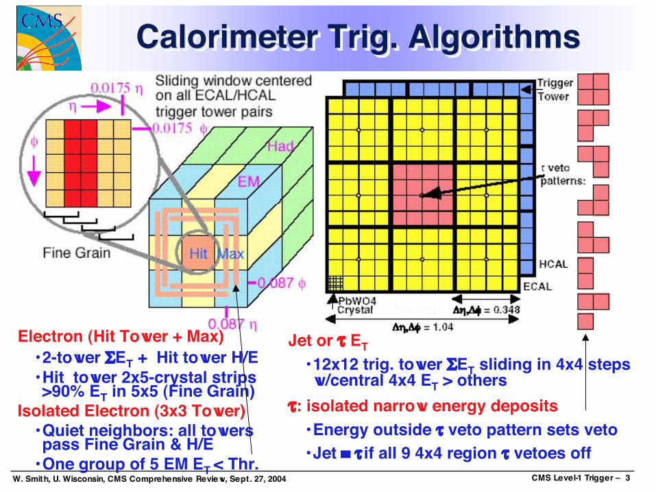
Electron (Hit Tower + Max)• 2-tower ΣET + Hit tower H/E• Hit tower 2x5-crystal strips>90% ET in 5x5 (Fine Grain)
Isolated Electron (3x3 Tower)• Quiet neighbors: all towerspass Fine Grain & H/E
• One group of 5 EM ET < Thr.
Jet or τ ET• 12x12 trig. tower ΣET sliding in 4x4 stepsw/central 4x4 ET > others
τ: isolated narrow energy deposits• Energy outside τ veto pattern sets veto• Jet ≡ τ if all 9 4x4 region τ vetoes off

W. Smith, U. Wisconsin, CMS Comprehensive Review, Sept. 27, 2004 CMS Level-1 Trigger – 4
Calorimeter Trigger Overview(in underground counting room — USC55)
Calorimeter Trigger OverviewCalorimeter Trigger Overview(in underground counting room — USC55)(in underground counting room — USC55)
, 3.0 < η < 5.0, 0 < η < 3.0

W. Smith, U. Wisconsin, CMS Comprehensive Review, Sept. 27, 2004 CMS Level-1 Trigger – 5
160 MHz point to point Backplane & Cards• 18 Clock&Control ,126 Electron ID & Receiver Cards
18 Jet/Summary Cards• Use 5 Custom Gate-Array 160 MHz GaAs Vitesse Digital ASICs
• Phase, Adder, Boundary Scan, Electron Isolation, Sort
Regional Calorimeter Trigger- U. Wisconsin
Regional Calorimeter TriggerRegional Calorimeter Trigger- U. Wisconsin- U. Wisconsin
Sparesnotincluded*
18 Crates:
Data from E/HCALcrates on Cu links@ 1.2 Gbaud•• Into 126Into 126 rearrearReceiverReceiverCardsCards
••Each withEach with8 Receiver8 ReceiverMezzanineMezzanineCardsCards(1026 total)(1026 total)

W. Smith, U. Wisconsin, CMS Comprehensive Review, Sept. 27, 2004 CMS Level-1 Trigger – 6
Regional Calorimeter Trigger Production:Crate, Backplane, Clock Cards - U. Wisconsin
Regional Calorimeter Trigger Production:Regional Calorimeter Trigger Production:Crate, Backplane, Clock Cards Crate, Backplane, Clock Cards - U. Wisconsin- U. Wisconsin
160 MHz Backplanew/0.4 Tbit/secdataflow:• All data paths
checked• Production
version validated• all backplanes
manufactured• 3/18+7sp testedRearRearFrontFront
Std.VMESlots
VME
48V externallysupplied
Clock Card:• Receives 160 MHz and 120 MHz clocks and resetsfrom Master Clock Card or generates clocks using anoscillator for standalone testing.
• Fans out and adjusts phase to all boards via backplane.• All 18/25 for operation/+ spares manufactured• 6 validated through full testing procedure• Integrated with full crate of RCT boards. Run withclock arriving via cable (from another CCC).
DC-DCConverters
Clockdelayadjust
VMEPowerSupply
VMEVMEPowerPowerSupplySupply
CustomPoint-to-point
Dataflow

W. Smith, U. Wisconsin, CMS Comprehensive Review, Sept. 27, 2004 CMS Level-1 Trigger – 7
RCT Production: Receiver Card (RC) &Receiver Mezzanine Card (RMC) — U. Wisconsin
RCT Production: Receiver Card (RC) &RCT Production: Receiver Card (RC) &Receiver Mezzanine Card (RMC)Receiver Mezzanine Card (RMC) — U. Wisconsin— U. Wisconsin
Front
DC-DC
Adder
mezzlink
cards
BSCANASICs
PHASEASICs
MLUs
Back
Receives 64 ECAL/HCAL trigger primitives and finegrain bits via Cu cable using 8 Vitesse 1.2 Gbaudlinks on RMCs.2 4x4 Tower sums are created and sent toJet/Summary Card with 2 MIP (OR of 4x4 HCAL FG)and 2 τ-veto bits (patterns).16 towers of ET sent directly to an ElectronIdentification Card and duplicated for edgeinformation for other cards.Crate-to-Crate sharing on cables of edge and cornertowers for e/γ algorithm.126/154 RCs necessary to operate/including sparesAll 154 manufactured and delivered, 5 validatedAll 1026/1420 RMCs delivered and testedFull crate tests performedInitial Integration with HCAL HTR & SLB performed,more tests planned with HCAL & ECAL
Bar Code

W. Smith, U. Wisconsin, CMS Comprehensive Review, Sept. 27, 2004 CMS Level-1 Trigger – 8
RCT 4 Gbaud Copper Link Cards &Serial Test Card — U. Wisconsin
RCT 4 Gbaud Copper Link Cards &RCT 4 Gbaud Copper Link Cards &Serial Test Card Serial Test Card — U. Wisconsin— U. Wisconsin
Compact Mezzanine
Cards for each
Receiver Card accept
4 x 20 m 1.2-Gbaudcopper pairs transmitting
2 cal. tower energies every25 ns with low cost & power.
Uses Vitesse Link Chips (7216–01).Serial Link Test Card
Status: Already commissioned, cables, cards, 48V PS, and support
software provided to groups.In use at CERN, operating in ECAL
Electronics lab for testing SLB.In use at Maryland for HCAL
HTR/SLB tests.Two pairs used @ UW for testing all
~1400 receiver mezzanine cards..10 cards(test only-not in final
system).
W. Smith, U. Wisconsin, CMS Comprehensive Review, Sept. 27, 2004 CMS Level-1 Trigger – 9
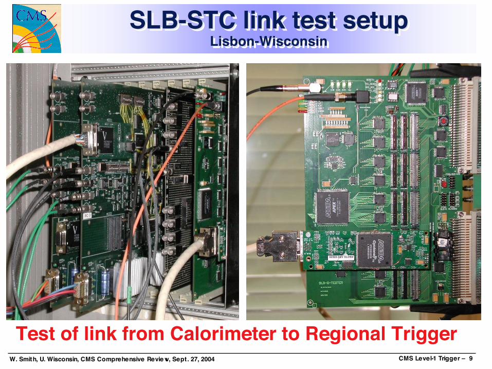
SLB-STC link test setupLisbon-Wisconsin
SLB-STC link test setupSLB-STC link test setupLisbon-WisconsinLisbon-Wisconsin
Test of link from Calorimeter to Regional Trigger

W. Smith, U. Wisconsin, CMS Comprehensive Review, Sept. 27, 2004 CMS Level-1 Trigger – 10
Electron Isolation Card (EIC)— U. Wisconsin
Electron Isolation Card (EIC)Electron Isolation Card (EIC)—— U. WisconsinU. Wisconsin
Receives 16 central towers directly fromadjoining RC and 32 edge and cornertowers from adjacent RC’s or via cablesinto adjoining RC.EISO ASIC uses this information toproduce one isolated and one non-isolated e/γ candidate for each 4x4trigger tower region which are sent viabackplane to Jet/Summary Card forsorting.126/154 for operation/total produced153 of 154 tested and working1 back to vendor for part replacementCompletely validated in full crate tests
SORTASICs(w/heatsinks)
EISO
EISO
Bar Code
SORT ASIC

W. Smith, U. Wisconsin, CMS Comprehensive Review, Sept. 27, 2004 CMS Level-1 Trigger – 11
Jet/Summary Card (JSC)— U. Wisconsin
Jet/Summary Card (JSC)Jet/Summary Card (JSC)—— U. WisconsinU. Wisconsin
Uses SORT ASICs to find top four e/γ, threshold for quiet bits.Receives 8 HF regions with Rec. Mezz. Card. Full crate test – alloutput/input paths verified, electron sort, jet output all verified.Integration test with GCT Done
18/25 for operation/including sparesRevision B 100% validated, Revision C (final) in production.
ReceiverMezz. Card
SortASICs
Output:14 Region ETSums, 14 eachMIP,t ,Quiet bits8 e/γ – 4 eachIso. and non-iso.On 6 CablesTo GCT(2 on Mezz. Card)
Input via Backplane:28 e/γ per 14 Region ETSums,MIP, t bits
BSCANASICs
BSCANASICs
PhaseASIC

W. Smith, U. Wisconsin, CMS Comprehensive Review, Sept. 27, 2004 CMS Level-1 Trigger – 12
RCT Full Crate Test - U. WisconsinRCT Full Crate Test RCT Full Crate Test - U. Wisconsin- U. Wisconsin
Full System Test of all pre-production prototypes in final configuration.
Rear: Receiver Cards Front: Electron, Jet, Clock Cards
W. Smith, U. Wisconsin, CMS Comprehensive Review, Sept. 27, 2004 CMS Level-1 Trigger – 13
Global Calorimeter Trigger— Bristol U.
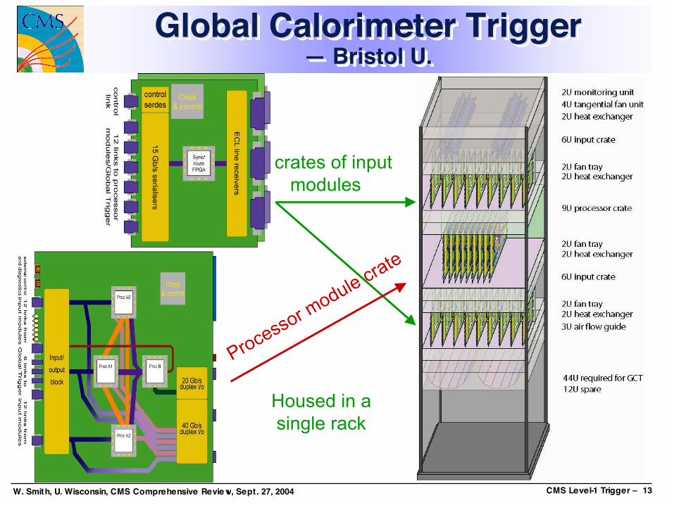
Global Calorimeter TriggerGlobal Calorimeter Trigger— Bristol U.— Bristol U.
2 crates of inputmodules
Processor module crate
Housed in asingle rack

W. Smith, U. Wisconsin, CMS Comprehensive Review, Sept. 27, 2004 CMS Level-1 Trigger – 14
Global Calorimeter Trigger:Input module prototyping —Bristol U.
Global Calorimeter Trigger:Global Calorimeter Trigger:Input module prototyping Input module prototyping —Bristol U.—Bristol U.
Tested first proto-IM in 2003• Full function, half channel count• Demonstrated data transfer input
from RCT, out to GT• Reported to 2003 Annual Review
Now testing pre-production IMs• Verified clocking, FPGA, TPM
interface• Built test boxes for ECL input
stage• Testing finished in Oct ’04
IM production to start Dec ’04

W. Smith, U. Wisconsin, CMS Comprehensive Review, Sept. 27, 2004 CMS Level-1 Trigger – 15
GCT Trigger Processor Module— Bristol U.
GCT Trigger Processor ModuleGCT Trigger Processor Module— Bristol U.— Bristol U.
Prototype TPMs were deliveredin January 2004
Verified clocking, links anddata paths
Second iteration prototype isrequired• Routing of TPM2 has started• Out to manufacture end Nov
Aiming for final productionJuly-Aug ’05

W. Smith, U. Wisconsin, CMS Comprehensive Review, Sept. 27, 2004 CMS Level-1 Trigger – 16
GCT hardware components— Bristol U.
GCT hardware componentsGCT hardware components— Bristol U.— Bristol U.
Crates, cables used in labtesting• Placing orders for final
production itemsCommunications Module for
clock fanout and DAQinterface• Testing started mid-
August• Looks good so far• Firmware effort needed

W. Smith, U. Wisconsin, CMS Comprehensive Review, Sept. 27, 2004 CMS Level-1 Trigger – 17
Muon Trigger OverviewMuon Trigger OverviewMuon Trigger Overview|η| < 1.2 |η| < 2.40.8 < |η| |η| < 2.1
|η| < 1.6 in 2007
Cav
ern:
UX
C55
Cou
ntin
g R
oom
: US
C55

W. Smith, U. Wisconsin, CMS Comprehensive Review, Sept. 27, 2004 CMS Level-1 Trigger – 18
RPC Trigger GeometryRPC Trigger GeometryRPC Trigger Geometry
DT
CSC
CSCstagedCoverage of
initial systemin 2007:
4 stations:up to η~ 1.24
3 stations:up to η ~1.6

W. Smith, U. Wisconsin, CMS Comprehensive Review, Sept. 27, 2004 CMS Level-1 Trigger – 19
RPC Electronics LayoutRPC Electronics LayoutRPC Electronics Layout
Bari/Laapperanta/Warsaw
Bari
Helsinki/Warsaw
(USC55)(UXC55)

W. Smith, U. Wisconsin, CMS Comprehensive Review, Sept. 27, 2004 CMS Level-1 Trigger – 20
RPC Link Boxes on Detector— Bari, Helsinki, Lappeenranta, Warsaw
RPC Link Boxes onRPC Link Boxes on DetectorDetector— — BariBari, Helsinki, , Helsinki, LappeenrantaLappeenranta, Warsaw, Warsaw
Link System tested & approved for production, cables & fibres ~ defined

W. Smith, U. Wisconsin, CMS Comprehensive Review, Sept. 27, 2004 CMS Level-1 Trigger – 21
RPC Trigger Splitter in USC55— Lappeenranta
RPC Trigger Splitter in USC55RPC Trigger Splitter in USC55— — LappeenrantaLappeenranta
• splitter outputafter 100 m fiber
• 80 MHz clock• 200 ps scale
Full size & function pre-production prototype tested• BER tests passed for 60 – 100 MHz clocks
• Ready for productionwith minor mods

W. Smith, U. Wisconsin, CMS Comprehensive Review, Sept. 27, 2004 CMS Level-1 Trigger – 22
4 PAC mezzanines
Readoutmezzanine
Bus of 54 lines@160 MHz
GhostBuster
18 OpticalLinks
LDEMUX FPGA
RPC Trigger Board— Warsaw
RPC Trigger BoardRPC Trigger Board— Warsaw— Warsaw
Pre-production prototype now being manufactured
Ghost Bustermezzanine

W. Smith, U. Wisconsin, CMS Comprehensive Review, Sept. 27, 2004 CMS Level-1 Trigger – 23
BACKPLANEFRONT
New RPC Sorter Crate— Bari
New RPC Sorter CrateNew RPC Sorter Crate— — BariBari
Sorter boards:• Under design
Read out Subsystem:• Customized DCC (ECAL) to be tested in October 2004

W. Smith, U. Wisconsin, CMS Comprehensive Review, Sept. 27, 2004 CMS Level-1 Trigger – 24
RPC Trigger in June 2004structured test beam
RPC Trigger in June 2004RPC Trigger in June 2004structured test beamstructured test beam
Chamber Efficiency
0,0000
0,2000
0,4000
0,6000
0,8000
1,0000
1,2000
8,6 8,7 8,8 8,9 9 9,1 9,2 9,3 9,4 9,5
HV [kV]
Two Gaps
One Gap
Oene Gap 2Cluster Size
0,00
0,50
1,00
1,50
2,00
2,50
3,00
3,50
8,7 8,8 8,9 9 9,1 9,2 9,3 9,4
HV [kV]
Clustersize
RE12 RPC efficiency:global, 1st gap, 2nd gap
Hits
0
500
1000
1500
2000
2500
3000
3500
4000
0 3 6 9 12 15 18 21 24 27 30 33 36 39 42 45 48 51 54 57 60 63
Strips
#
Scintillatortrigger
Beam profile

W. Smith, U. Wisconsin, CMS Comprehensive Review, Sept. 27, 2004 CMS Level-1 Trigger – 25
1 2 3 4 5
100
1000
10000
Muons/ R
eadout bx
Readout bx
It seems that the RPC data will be useful for the CSC TF
RPC data in thebuffer for TF trigger
TF trigger and RPC data atThe same BX
TF trigger 1BX too early
June 2004 RPC TriggerSynchronization with CSC Trigger
June 2004 RPC TriggerJune 2004 RPC TriggerSynchronization with CSC TriggerSynchronization with CSC Trigger
Initial results promisingMore tests during the October 25ns beam test.
W. Smith, U. Wisconsin, CMS Comprehensive Review, Sept. 27, 2004 CMS Level-1 Trigger – 26
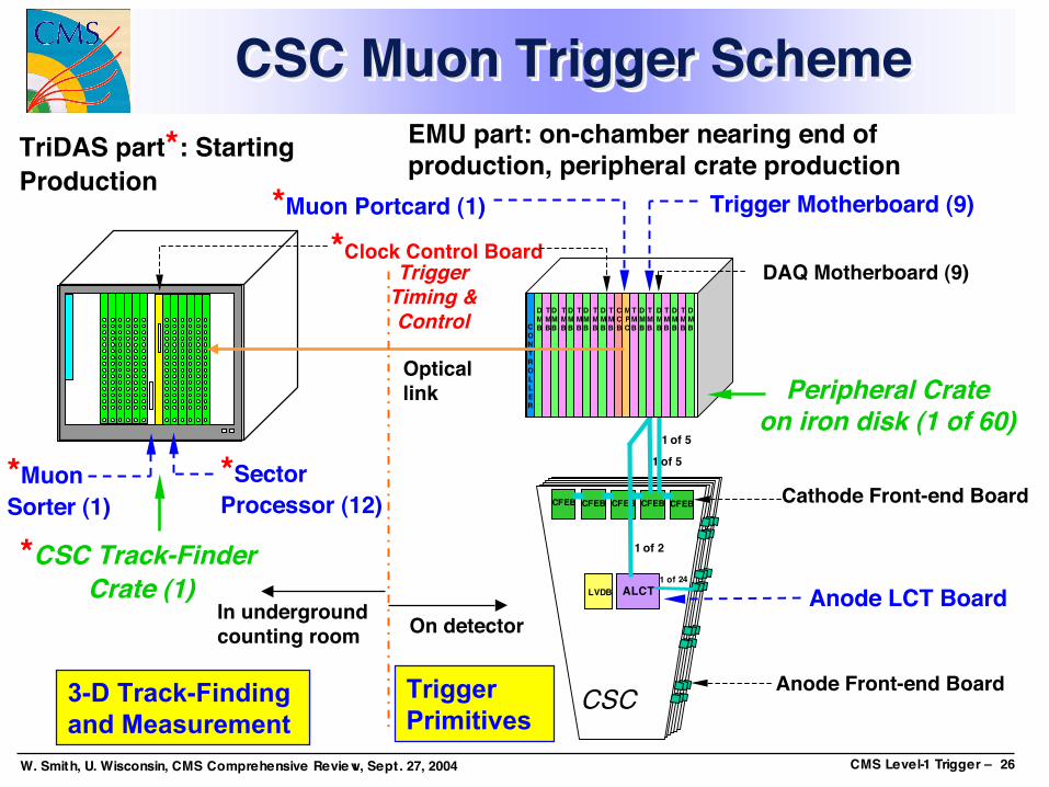
CSC Muon Trigger SchemeCSC Muon Trigger SchemeCSC Muon Trigger Scheme
CSC
CFEBCFEBCFEB CFEB
ALCT1 of 24
CFEB
1 of 2
LVDB
1 of 5
1 of 5
Anode Front-end Board
Cathode Front-end Board
Anode LCT Board
MPC
DMB
TMB
DMB
TMB
DMB
TMB
DMB
TMB
DMB
TMB
DMB
TMB
DMB
TMB
DMB
TMB
DMB
TMB
CCBC
ONTROLLER
Peripheral Crateon iron disk (1 of 60)
TriggerTiming &Control
*CSC Track-Finder Crate (1)
Trigger Motherboard (9)
DAQ Motherboard (9)*Clock Control Board
Opticallink
In undergroundcounting room On detector
*Muon Portcard (1)
EMU part: on-chamber nearing end ofproduction, peripheral crate productionTriDAS part*: Starting
Production
TriggerPrimitives
3-D Track-Findingand Measurement
*SectorProcessor (12)
*MuonSorter (1)

W. Smith, U. Wisconsin, CMS Comprehensive Review, Sept. 27, 2004 CMS Level-1 Trigger – 27
CSC Trigger June 2004Structured Beam TestsCSC Trigger June 2004CSC Trigger June 2004Structured Beam TestsStructured Beam Tests
ME 1/1
ME 1/2
ME 2/2
ME 3/2
RE1/2
Peripheral Crate#1ME1/1+ME1/2
Peripheral Crate#2ME2/2+ME3/2
RPC LinkboardCrate
Each has 2TMB, 1 MPC
First time used full Track-Finding logic to identify tracks in dataFull DAQ logging of inputs and outputs for offline comparisons
• Compare with data sent by Peripheral Crates & internal TF logic L1A generation a major synchronization accomplishment for trigger
• Data must be aligned spatially and temporally• Very useful for slice tests
Track-Finder Crate(next slide)
W. Smith, U. Wisconsin, CMS Comprehensive Review, Sept. 27, 2004 CMS Level-1 Trigger – 28
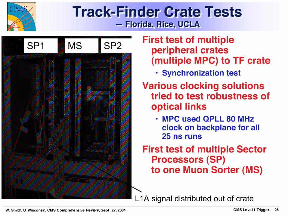
Track-Finder Crate Tests— Florida, Rice, UCLA
Track-Finder Crate TestsTrack-Finder Crate Tests— Florida, Rice, UCLA— Florida, Rice, UCLA
First test of multipleperipheral crates(multiple MPC) to TF crate• Synchronization test
Various clocking solutionstried to test robustness ofoptical links• MPC used QPLL 80 MHz
clock on backplane for all25 ns runs
First test of multiple SectorProcessors (SP)to one Muon Sorter (MS)
SP1 SP2MS
L1A signal distributed out of crate

W. Smith, U. Wisconsin, CMS Comprehensive Review, Sept. 27, 2004 CMS Level-1 Trigger – 29
CSC Track-Finder Beam Tests— Florida, Rice, UCLA
CSC Track-Finder Beam TestsCSC Track-Finder Beam Tests— Florida, Rice, UCLA— Florida, Rice, UCLA
Fully operational CSC TF tested with full data formatAgreement between the output of the Sector Processor
(SP) with simulation based on logged inputs is 100%Agreement between the recorded trigger primitive data (via
DAQ from Trigger Mother Board) and received SP data isgenerally at the level of 99.7%• Same level of agreement as obtained from the Sep.’03 beam test
The SP in conjunction with a specially modified Clock andControl Board was able to self-trigger the experiment(including RPC)
Muon Sorter winner bits appear to be properly recordedNew DT/CSC transition card works

W. Smith, U. Wisconsin, CMS Comprehensive Review, Sept. 27, 2004 CMS Level-1 Trigger – 30
CSC Trigger Muon Port Card &Clock & Control Board — Rice
CSC Trigger Muon PortCSC Trigger Muon Port Card &Card &Clock & Control Board Clock & Control Board — Rice— Rice
Muon Port Card:• 6 boards built in 2002, equippedwith FPGA mezzanines
• Tested on the bench• Tested w/7 Trigger Motherboards& one Sector Processor
• Checked in peripheral crates inbeam test at CERN inSept. 2003 & June 2004
• Radiation tested at UC Daviscyclotron
Clock & Control Board;• 6 boards built in spring 2004, equipped withTTCrq mezzanines
• Tested on the bench• Tested w/7 Trigger Motherboards& one Sector Processor
• Checked in peripheral crates inbeam test at CERN in June 2004
• Radiation tested at UC Davis cyclotron
W. Smith, U. Wisconsin, CMS Comprehensive Review, Sept. 27, 2004 CMS Level-1 Trigger – 31
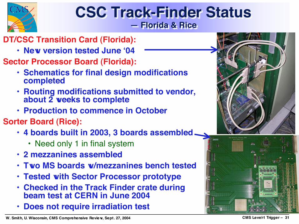
CSC Track-Finder Status— Florida & Rice
CSC Track-Finder StatusCSC Track-Finder Status—— Florida & RiceFlorida & Rice
DT/CSC Transition Card (Florida):• New version tested June ‘04
Sector Processor Board (Florida):• Schematics for final design modifications
completed• Routing modifications submitted to vendor,
about 2 weeks to complete• Production to commence in October
Sorter Board (Rice):• 4 boards built in 2003, 3 boards assembled
• Need only 1 in final system• 2 mezzanines assembled• Two MS boards w/mezzanines bench tested• Tested with Sector Processor prototype• Checked in the Track Finder crate during
beam test at CERN in June 2004• Does not require irradiation test
W. Smith, U. Wisconsin, CMS Comprehensive Review, Sept. 27, 2004 CMS Level-1 Trigger – 32
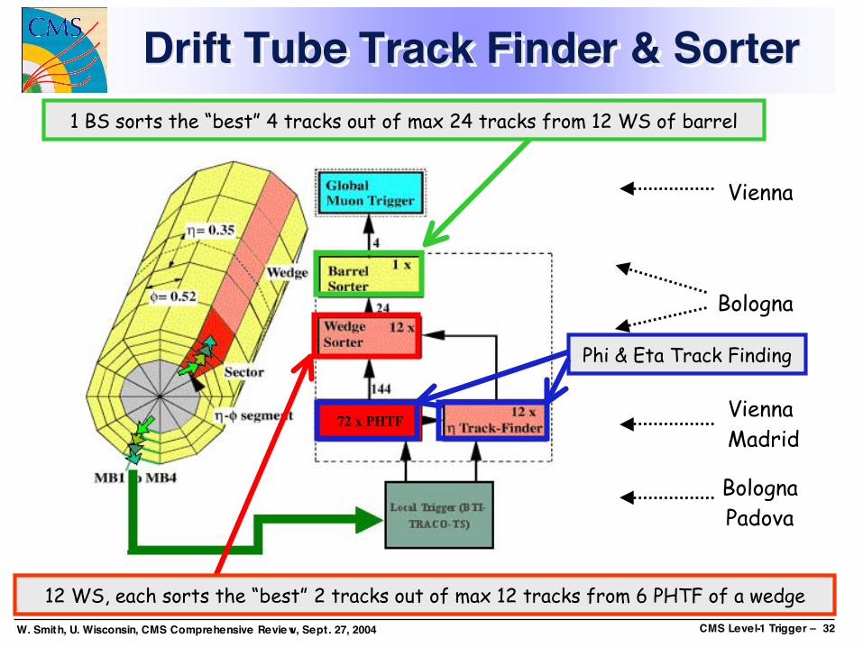
Drift Tube Track Finder & SorterDrift Tube Track Finder & SorterDrift Tube Track Finder & Sorter
Vienna
ViennaMadrid
BolognaPadova
Bologna
12 WS, each sorts the “best” 2 tracks out of max 12 tracks from 6 PHTF of a wedge
1 BS sorts the “best” 4 tracks out of max 24 tracks from 12 WS of barrel
72 x PHTF
Phi & Eta Track Finding
W. Smith, U. Wisconsin, CMS Comprehensive Review, Sept. 27, 2004 CMS Level-1 Trigger – 33
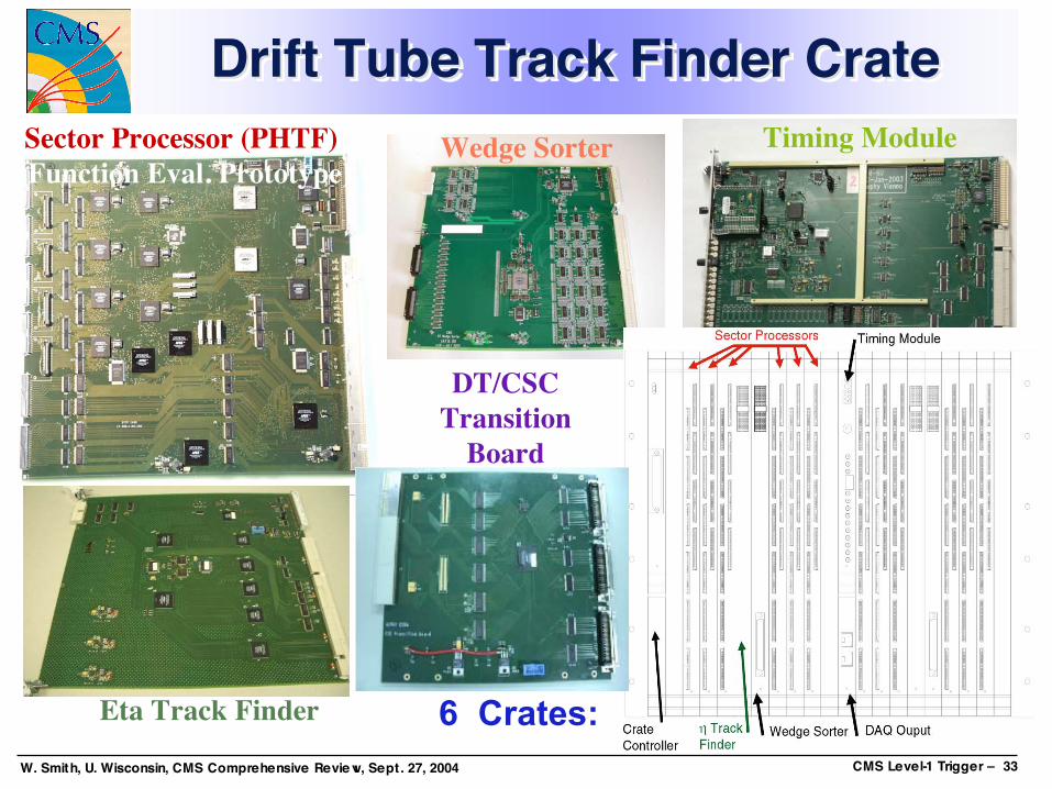
Drift Tube Track Finder CrateDrift TubeDrift Tube Track Finder CrateTrack Finder CrateSector Processor (PHTF) (Function Eval. Prototype)
Timing Module
Eta Track Finder
Wedge Sorter
DT/CSCTransition
Board
6 Crates:
W. Smith, U. Wisconsin, CMS Comprehensive Review, Sept. 27, 2004 CMS Level-1 Trigger – 34
Phi & Eta Track Finders— Vienna & Madrid
Phi & Phi & Eta Eta Track FindersTrack Finders— Vienna & Madrid— Vienna & Madrid
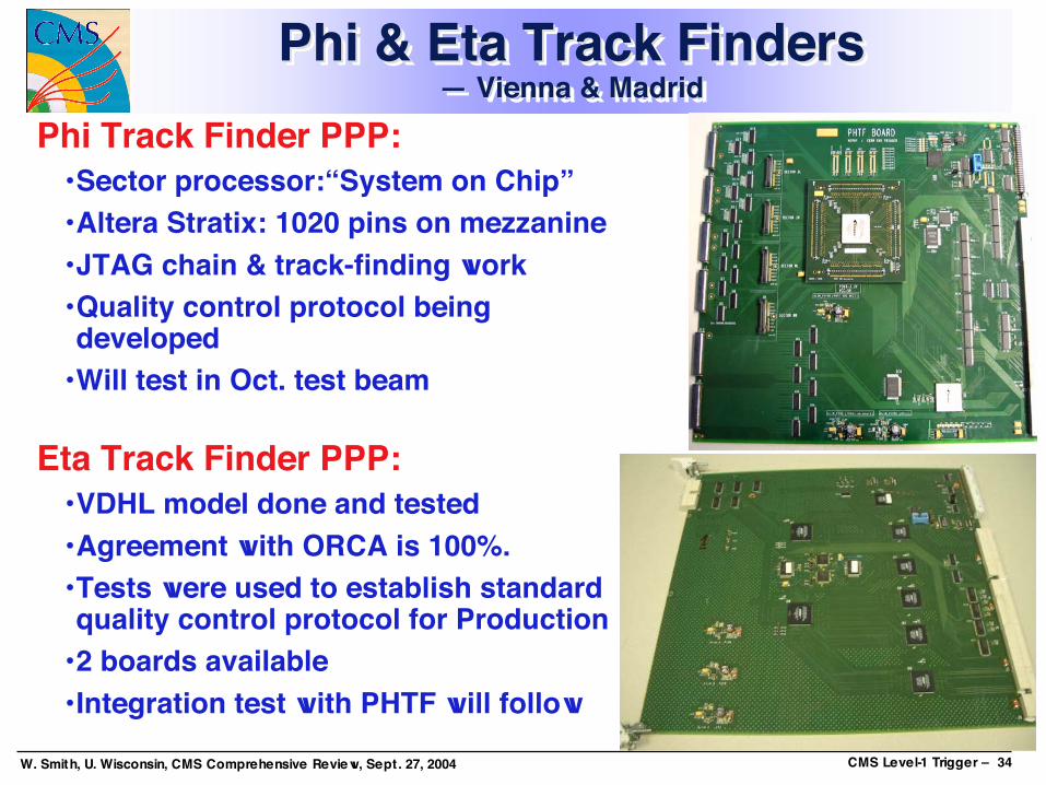
Phi Track Finder PPP:•Sector processor:“System on Chip”•Altera Stratix: 1020 pins on mezzanine•JTAG chain & track-finding work•Quality control protocol beingdeveloped
•Will test in Oct. test beam
Eta Track Finder PPP:•VDHL model done and tested•Agreement with ORCA is 100%.•Tests were used to establish standardquality control protocol for Production
•2 boards available• Integration test with PHTF will follow

W. Smith, U. Wisconsin, CMS Comprehensive Review, Sept. 27, 2004 CMS Level-1 Trigger – 35
Drift Tube Wedge & Barrel Sorters— Bologna
Drift Tube Wedge & Barrel SortersDrift Tube Wedge & Barrel Sorters— Bologna— Bologna
Wedge Sorter:• Prototype fully tested @ 40 MHz standalone• Combined static test done with old PHTF• Combined test @ 40 MHz w/new PHTF now• Will test in October test beam• Tender for production done• Production starts Oct 04, ends Dec 04
on scheduleBarrel Sorter:
• Electrical design for main board (VME 9U,with all connectors & transceivers) done
• Mezzanine design under way: ghostbusting & sorting 4 out 24 in 3 BX iscomplex fits only in a big Stratix II FPGA(1508 pins)
• Prototype expected by end Nov 04
W. Smith, U. Wisconsin, CMS Comprehensive Review, Sept. 27, 2004 CMS Level-1 Trigger – 36
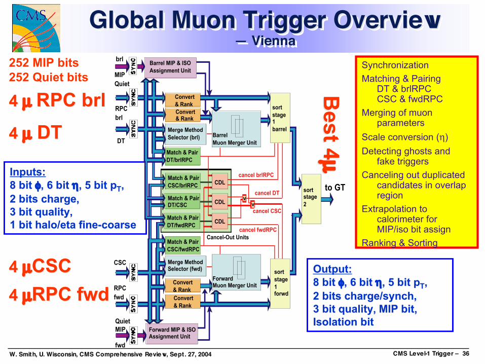
Global Muon Trigger Overview— Vienna
Global Muon Trigger OverviewGlobal Muon Trigger Overview— Vienna— Vienna
Output:Output:8 8 bit bit φφ, 6 , 6 bit bit ηη, 5 , 5 bit pbit pTT,,2 2 bits charge/synchbits charge/synch,,3 3 bit qualitybit quality,, MIP MIP bitbit,,Isolation Isolation bitbit
Inputs:Inputs:8 8 bit bit φφ, 6 , 6 bit bit ηη, 5 , 5 bit pbit pTT,,2 2 bits chargebits charge,,3 3 bit qualitybit quality,,1 1 bit halo/eta fine-coarsebit halo/eta fine-coarse
4 4 µµ RPC RPC brlbrl
4 4 µµ DT DT
4 4 µµCSCCSC
4 4 µµRPC fwdRPC fwd
252 MIP bits252 Quiet bits
RPC
brl
RPC
fwd
CSC
DT
cancel CSC
cancel DT
sort
stage1
barrel
sort
stage
1forwd
sortstage
2
Barrel
Muon Merger Unit
ForwardMuon Merger Unit
Match & Pair
DT/brlRPC
Match & Pair
CSC/fwdRPC
Convert
& Rank
to GT
Convert& Rank
Convert
& Rank
Convert
& Rank
Forward MIP & ISOAssignment Unit
Quiet
MIP
brlBarrel MIP & ISO
Assignment UnitMIP
Quiet
fwd
Match & PairDT/CSC
Match & Pair
CSC/brlRPC
Match & Pair
DT/fwdRPC
cancel brlRPC
cancel fwdRPC
vv
CDL
Cancel-Out Units
CDL
CDL
Merge Method
Selector (brl)
Merge MethodSelector (fwd)
Synchronization
Matching & PairingDT & brlRPCCSC & fwdRPC
Merging of muonparameters
Scale conversion (η)
Detecting ghosts andfake triggers
Canceling out duplicatedcandidates in overlapregion
Extrapolation tocalorimeter forMIP/iso bit assign
Ranking & Sorting
Best 4
Best 4µ µ

W. Smith, U. Wisconsin, CMS Comprehensive Review, Sept. 27, 2004 CMS Level-1 Trigger – 37
Logic Board• Mezzanine for FF896 package built & tested
• For Input FPGAs• Mezzanine for BF957 produced & under test
• For Logic, MIP/ISO Assignment, Sort FPGAs• Schematics complete• Layout & routing complete, final checks now
• For both GMT Logic Board and Input Board• Production planned this month,
• Available Oct./Nov. 2004, tests until Dec. 04• Integration tests possible from Jan. 05
Firmware: 10 Xilinx Virtex II FPGAs• All chips completed (New: Sorter, Input FPGAs, Readout Processor)• All verified against ORCA simulation. 100% agreement.
Online Software• Developed generic JTAG Access Library (JAL) to program the flash PROMs
via VME (common project with DT, GT)
Global Muon Trigger Status— Vienna
Global Muon Trigger StatusGlobal Muon Trigger Status— Vienna— Vienna
SCSIconn.
Inputbd.conn.
LVDSRec.
InputFPGAs
Sort &LogicFPGAs

W. Smith, U. Wisconsin, CMS Comprehensive Review, Sept. 27, 2004 CMS Level-1 Trigger – 38
Boards in Global Trigger Crate— Vienna
Boards in Global Trigger CrateBoards in Global Trigger Crate— Vienna— Vienna
The Global Trigger Processor consists of the following electronics boards:
PSB (Pipelined Synchronizing Buffer) Synchronization of inputs (7 modules)
GTL (Global Trigger Logic) Global Trigger logic (1–2 modules)
GMT (Global Muon Trigger) Global Muon Trigger logic (1 module, 4 slots wide)
FDL (Final Decision Logic) Trigger decision (1 module)
TCS (Trigger Control System Module) Central trigger control (1 module, 2 slots wide)
CONV6U (Conversion Boards) Reception of fast signals
L1A (Level-1 Accept Module) Distribution of trigger decision (2 modules)
TIM (Timing Board) Timing (1 module)
GTFE (Global Trigger Frontend) Readout (1 module)
W. Smith, U. Wisconsin, CMS Comprehensive Review, Sept. 27, 2004 CMS Level-1 Trigger – 39
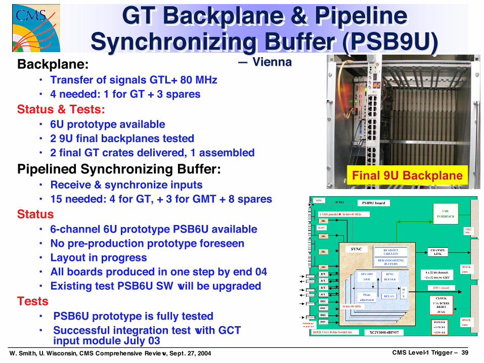
Final 9U Backplane
GT Backplane & PipelineSynchronizing Buffer (PSB9U)
— Vienna
GT Backplane & PipelineGT Backplane & PipelineSynchronizing Buffer (PSB9U)Synchronizing Buffer (PSB9U)
— Vienna— ViennaBackplane:• Transfer of signals GTL+ 80 MHz• 4 needed: 1 for GT + 3 spares
Status & Tests:• 6U prototype available• 2 9U final backplanes tested• 2 final GT crates delivered, 1 assembled
Pipelined Synchronizing Buffer:• Receive & synchronize inputs• 15 needed: 4 for GT, + 3 for GMT + 8 spares
Status• 6-channel 6U prototype PSB6U available• No pre-production prototype foreseen• Layout in progress• All boards produced in one step by end 04• Existing test PSB6U SW will be upgraded
Tests• PSB6U prototype is fully tested• Successful integration test with GCT
input module July 03
W. Smith, U. Wisconsin, CMS Comprehensive Review, Sept. 27, 2004 CMS Level-1 Trigger – 40
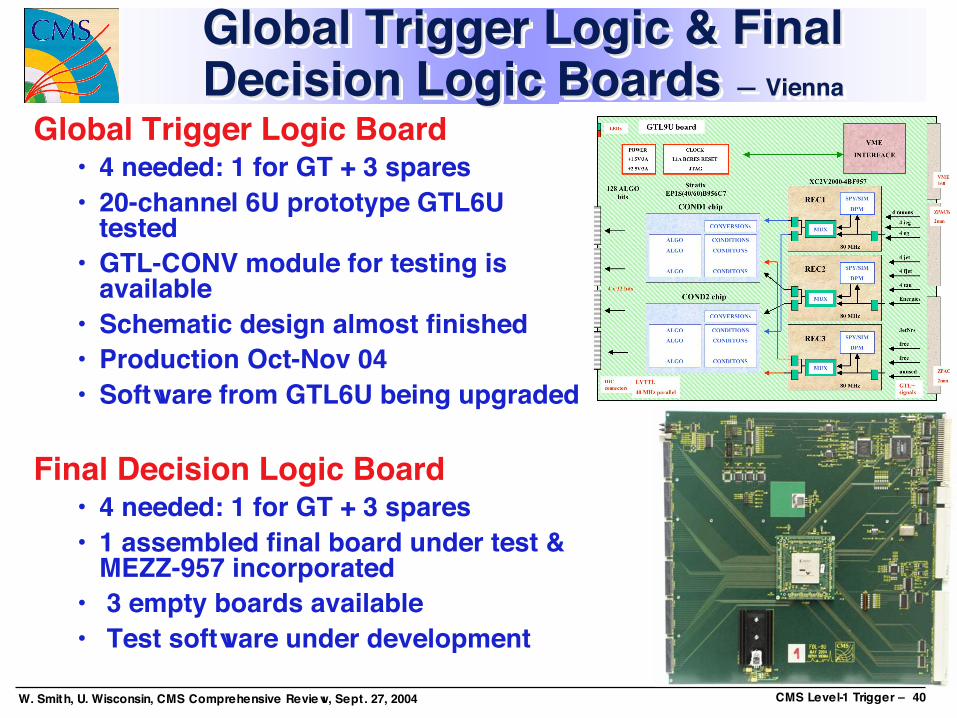
Global Trigger Logic & FinalDecision Logic Boards — Vienna
Global Trigger Logic & FinalGlobal Trigger Logic & FinalDecision Logic Boards Decision Logic Boards — Vienna— Vienna
Global Trigger Logic Board• 4 needed: 1 for GT + 3 spares• 20-channel 6U prototype GTL6U
tested• GTL-CONV module for testing is
available• Schematic design almost finished• Production Oct-Nov 04• Software from GTL6U being upgraded
Final Decision Logic Board• 4 needed: 1 for GT + 3 spares• 1 assembled final board under test &
MEZZ-957 incorporated• 3 empty boards available• Test software under development
W. Smith, U. Wisconsin, CMS Comprehensive Review, Sept. 27, 2004 CMS Level-1 Trigger – 41
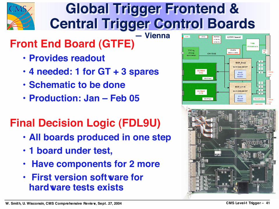
Global Trigger Frontend &Central Trigger Control Boards
— Vienna
Global TriggerGlobal Trigger Frontend Frontend &&Central Trigger Control BoardsCentral Trigger Control Boards
— Vienna— ViennaFront End Board (GTFE)
• Provides readout• 4 needed: 1 for GT + 3 spares• Schematic to be done• Production: Jan – Feb 05
Final Decision Logic (FDL9U)• All boards produced in one step• 1 board under test,• Have components for 2 more• First version software for
hardware tests exists
W. Smith, U. Wisconsin, CMS Comprehensive Review, Sept. 27, 2004 CMS Level-1 Trigger – 42
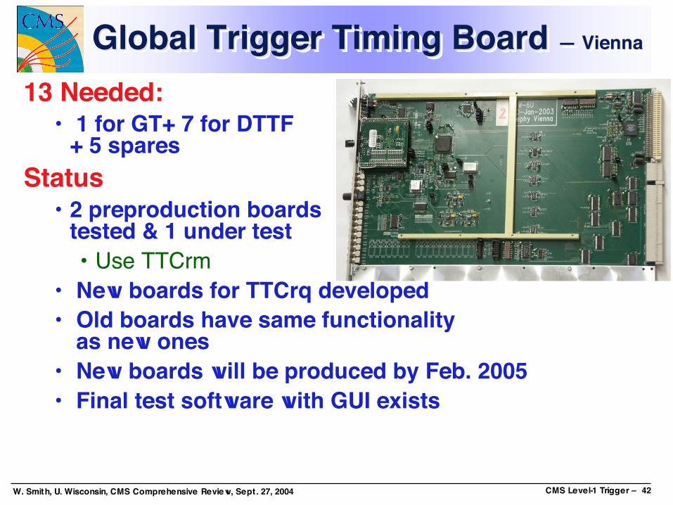
Global Trigger Timing Board — ViennaGlobal Trigger Timing Board Global Trigger Timing Board — Vienna— Vienna
13 Needed:• 1 for GT+ 7 for DTTF
+ 5 sparesStatus
• 2 preproduction boardstested & 1 under test• Use TTCrm
• New boards for TTCrq developed• Old boards have same functionality
as new ones• New boards will be produced by Feb. 2005• Final test software with GUI exists

W. Smith, U. Wisconsin, CMS Comprehensive Review, Sept. 27, 2004 CMS Level-1 Trigger – 43
Trigger Module DatabaseTrigger ModuleTrigger Module DatabaseDatabaseSubsys. Item Explanation Needed Total Responsible Status
Prod.
Start
Prod.
Finish
Prod.
Test
Start
Prod. %
Compl.
Prod.
Test
Finish
Prod.
Test %
Compl.
Ready for
904
Ready for
USC55CSC CCB CSC Clock & Control Board 1 3 Rice PPP Oct-04 Jan-05 Dec-04 0% Mar-05 0% Apr-05 Jun-05CSC CSC Bckpl CSC Track - Finder Crate Backplane 1 3 U. Florida PPP Oct-04 Jan-05 Dec-04 0% Mar-05 0% Apr-05 Jun-05CSC MPC CSC Muon Port Card 60 72 Rice PPP Oct-04 Jan-05 Dec-04 0% Mar-05 0% Apr-05 Jun-05CSC SR/SP CSC Sector Processor/ Receiver 12 15 U. Florida PPP Oct-04 Jan-05 Dec-04 0% Mar-05 0% Apr-05 Jun-05CSC Sort CSC Track-Finder Sorter 1 3 Rice PPP Jan-05 Feb-05 Feb-05 0% Mar-05 0% Apr-05 Jun-05DT DT Backplane Drift Tube Track-Finder Crate Backplane 6 8 Vienna PPP Jan-05 Mar-05 Mar-05 0% Apr-05 0% Feb-05 Jun-05DT PHTF Drift Tube Phi Track-Finder 72 90 Vienna PPP-Aug-04 Jan-05 Mar-05 Mar-05 0% Apr-05 0% Feb-05 Jul-05DT ETTF Drift Tube Eta Track-Finder 12 15 Vienna PPP Nov-04 Dec-04 Dec-04 0% Feb-05 0% Feb-05 Jun-05DT Optical Input DTTF Gigabit Optical Receiver 96 110 Bologna PPP-Nov-04 Apr-05 Aug-05 Apr-05 0% Aug-05 0% May-05 Sep-05DT WS Drift Tube Wedge Sorter 12 15 Bologna PPP-Nov-04 Dec-04 Jan-05 Dec-04 0% Feb-05 0% Feb-05 Mar-05DT BS Drift Tube Barrel Sorter 1 3 Bologna PPP-Nov-04 Jan-05 Feb-05 Jan-05 0% Mar-05 0% Mar-05 Apr-05DT TIM Timing Module 7 10 Vienna PPP Jan-05 Feb-05 Feb-05 0% Apr-05 0% Feb-05 Jun-05DT Data-Link DTTF Data Concentrator Interface 6 8 Vienna PPP-Sep-04 Oct-04 Jul-04 Sep-04 0% Feb-05 0% Feb-05 Jun-05DT CSC Transition Data-Link between DTTF & CSC TF systems 24 30 Vienna PPP Oct-04 Dec-04 Jan-05 0% Feb-05 0% Feb-05 Jun-05DT Data Concentrator DTTF Data Collection, Compression, DAQ Link 1 3 Vienna PPP-Oct-04 Feb-05 Aug-04 Sep-04 0% Apr-05 0% Feb-05 Jun-05DT Control Backplane DTTF Control Crate Backplane 1 3 Vienna - Nov-04 Dec-04 Dec-04 0% Dec-04 0% Feb-05 Jun-05GCT IM Input Module 18 22 Bristol PPP Dec-04 Jan-05 Feb-05 0% Mar-05 0% Apr-05 Apr-05GCT IM Backplane Input Module Crate Backplane 2 4 Bristol PPP Dec-04 Jan-05 Feb-05 0% Mar-05 0% Apr-05 Apr-05GCT TPM Trigger Processor Module 9 12 Bristol PPP-Oct-04 Jul-05 Aug-05 Aug-05 0% Dec-05 0% Mar-05 Dec-05GCT TPM Backplane Trigger Processor Module Crate Backplane 1 3 Bristol PPP Jul-05 Aug-05 Aug-05 0% Dec-05 0% Mar-05 Dec-05GCT CM Communications Module 1 4 Bristol PPP-Jul-04 Jul-05 Aug-05 Aug-05 0% Dec-05 0% Mar-05 Dec-05GMT TLB Trigger Logic Board 1 4 Vienna Design Aug-04 Oct-04 Oct-04 0% Nov-04 0% Dec-04 Jun-05GMT PSB Pipeline Synchronization Buffer Board 3 6 Vienna Final Sep-04 Nov-04 Nov-04 0% Dec-04 0% Dec-04 Jun-05GT Backplane Global Trigger Backplane 1 3 Vienna Final Dec-03 Apr-04 May-04 100% Jun-04 100% Oct-04 Jun-05GT PSB Pipeline Synchronization Buffer Board 4 9 Vienna Final Sep-04 Nov-04 Nov-04 0% Dec-04 0% Dec-04 Jun-05GT GTL6U Global Trigger Logic Board 1 4 Vienna Proto Oct-02 Nov-03 Nov-03 100% Apr-04 100% Oct-04 Jun-05GT GTL Global Trigger Logic Board 1 4 Vienna Final Dec-04 Feb-05 Feb-05 0% Apr-05 0% Jun-05 Aug-05GT FDL Final Decision Logic Board 1 4 Vienna Final Jun-04 Sep-04 Sep-04 50% Nov-04 0% Nov-04 Jun-05GT GTFE Global Trigger Front End - Readout 1 3 Vienna Final Feb-05 Mar-05 Mar-05 0% Jun-05 0% Jun-05 Aug-05GT TCS Central Trigger Control System Board 1 3 Vienna Final Dec-03 Jun-04 Jun-04 100% Oct-04 50% Oct-04 Jun-05GT L1A Level 1 Accept Output Module 2 5 Vienna Final Mar-04 Aug-04 Jul-04 80% Oct-04 50% Oct-04 Jun-05GT CONV Fast Signal Converter Boards 4 10 Vienna Final Dec-03 Jun-04 Jul-04 25% Oct-04 50% Oct-04 Jun-05GT TIM_V1 (for TTCrm) Timing Module 1 3 Vienna PPP Jan-03 Mar-03 Mar-03 100% Jun-03 100% Oct-04 Jun-05GT TIM_V2 (for TTCrq) Timing Module 1 3 Vienna Final Jan-05 Mar-05 Apr-05 0% May-05 0% May-05 Jun-05RCT Bckpl Regional Cal Trigger Backplane 18 25 Wisconsin Exist Jan-04 Jun-04 Jun-04 100% Oct-04 12% Dec-04 Jun-05RCT CCC Clock and Control Card 18 25 Wisconsin Exist Jan-04 Jun-04 Jun-04 100% Oct-04 20% Dec-04 Jun-05RCT RC Receiver Card 126 154 Wisconsin Exist Jan-04 Aug-04 Nov-04 100% Oct-04 2% Dec-04 Jun-05RCT RMC Receiver Mezzanine Card 1026 1420 Wisconsin Done Sep-03 Oct-03 Oct-03 100% Dec-03 100% Dec-04 Jun-05RCT EIC Electron Identification Card 126 154 Wisconsin Done Jan-04 Mar-04 Mar-04 100% Oct-04 100% Dec-04 Jun-05RCT JSC Jet/Summary Card 18 25 Wisconsin PPP Aug-04 Sep-04 Oct-04 0% Nov-04 0% Dec-04 Jun-05RCT MCC Master Clock Card 1 3 Wisconsin Design Jan-05 Feb-05 Feb-05 0% Mar-05 0% Mar-05 Jun-05RPC LB Link Box (includes front & back planes) 108 124 Lapp./Wars. PPP Mar-04 Jun-04 Oct-04 0% Jun-05 0% May-05 May-05RPC MLB Master Link Board 588 676 Lapp./Wars. PPP Mar-04 Jun-04 Oct-04 0% Sep-04 0% May-05 May-05RPC SLB Slave Link Board 980 1127 Lapp./Wars. PPP Mar-04 Jun-04 Oct-04 0% Sep-04 0% May-05 May-05RPC CB Control Board 216 248 Lapp./Wars. PPP Mar-04 Jun-04 Oct-04 0% Sep-04 0% May-05 May-05RPC LBbox RE11 Link Box RE11 (includes front & back planes) 12 14 Lapp./Wars. PPP Apr-04 Jun-04 Oct-04 0% Dec-04 0% UX UXRPC MLB RE11 Master Link Board RE11 72 84 Lapp./Wars. Proto Mar-04 May-04 Mar-05 0% Dec-05 0% UX UXRPC CB RE11 Control Board RE11 12 14 Lapp./Wars. Proto Mar-04 May-04 Mar-05 0% Dec-05 0% UX UXRPC Splitter Splitter Board 60 69 Lappeenranta PPP Aug-04 Sep-04 Nov-04 0% Feb-05 0% Apr-05 Jul-05RPC Trigger Backplane Trigger Crate Backplane 12 14 Warsaw PPP-Oct04 Jul-04 Sep-04 Jan-05 0% Mar-05 0% Apr-05 Jul-05RPC TB Trigger Board 108 124 Warsaw PPP Jun-04 Sep-04 Jan-05 0% Dec-05 0% Apr-05 Jul-05RPC Sorter Backplane Sorter Crate Backplane 1 3 Bari/Warsaw Design Nov-04 Mar-05 Apr-05 0% May-05 0% Jun-05 Jul-05RPC SB Sorter Board 1 3 Bari Design Mar-05 May-05 Jun-05 0% Dec-05 0% Jul-05 Jul-05RPC Final Sorter Board Ghost-Buster & Sorter Board 2 4 Bari Design Jun-04 May-05 Jun-05 0% Dec-05 0% Jul-05 Jul-05RPC DCC Data Concentrator Card 3 5 Warsaw/ECAL PPP Jan-05 May-05 Jun-05 0% Dec-05 0% Jul-05 Jul-05RPC CCS Clock and Control System 3 5 Warsaw/Tracker PPP Jan-05 May-05 Jun-05 0% Dec-05 0% Jul-05 Jul-05

W. Smith, U. Wisconsin, CMS Comprehensive Review, Sept. 27, 2004 CMS Level-1 Trigger – 44
Trigger Software StatusTrigger Software StatusTrigger Software Status Software for test of trigger boards was
developed for all trigger sub-systems Most of the software is based on standard CMS
tools (XDAQ, HAL, SOAP, I2O) and can be re-used later in the experiment
Configuration, Operation, Monitoring andTesting functions are becoming available
Software teams for all trigger sub-systems arenow in place
Focusing on Coordination — J. Varela, Lisbon

W. Smith, U. Wisconsin, CMS Comprehensive Review, Sept. 27, 2004 CMS Level-1 Trigger – 45
CALO TRIGGER
PC
HW
PC
HW
PC
HW
PC
Local User Interface
PC
HW
PC
HW
PC
HW
PC
Local User Interface
PC
HW
PC
HW
PC
HW
PC
Local User Interface
...RPC TRIGGER GLOBAL TRIGGER
Trigger Software Supervisor
RCS Local User Interface
Level of present developments:
Single trigger crate XDAQ application GUI Controller
Trigger Software StructureTrigger Software StructureTrigger Software Structure
W. Smith, U. Wisconsin, CMS Comprehensive Review, Sept. 27, 2004 CMS Level-1 Trigger – 46
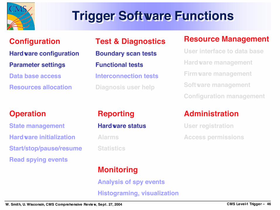
ConfigurationHardware configurationParameter settingsData base accessResources allocation
OperationState managementHardware initializationStart/stop/pause/resumeRead spying events
Test & DiagnosticsBoundary scan testsFunctional testsInterconnection testsDiagnosis user help
MonitoringAnalysis of spy eventsHistograming, visualization
ReportingHardware statusAlarmsStatistics
Resource ManagementUser interface to data baseHardware managementFirmware managementSoftware managementConfiguration management
AdministrationUser registrationAccess permissions
Trigger Software FunctionsTrigger Software FunctionsTrigger Software Functions

W. Smith, U. Wisconsin, CMS Comprehensive Review, Sept. 27, 2004 CMS Level-1 Trigger – 47
New composition:
Emlyn CorrinTTCJoscko StraussGTJeremy MansHCALNuno AlmeidaECALMonika GrotheRCTJim BrookeGCT
DTJorge TroconizDTTFMichal PietrusinkiRPCDarin AcostaCSCHannes SakulinGMTIldefons MagransTSJoao VarelaChair
PeopleSub-System
Trigger Software Working GroupTrigger Software Working GroupTrigger Software Working Group

W. Smith, U. Wisconsin, CMS Comprehensive Review, Sept. 27, 2004 CMS Level-1 Trigger – 48
Trigger SW Development PlanTrigger SW Development PlanTrigger SW Development PlanConsolidate sub-systems software teams & present work:
• Document what exists• Promote use of common technologies
• XDAQ, HAL, SOAP, I2O, DSTOREConsolidate hardware related layer:
• Hardware management in Equipment Database• Board description, identification & history
• Agree on scheme for storage and verification of Firmware and LUT contentsConfiguration data
• Use CMS Configuration DB Infrastructure (need this)• Sub-systems define their Configuration Data Schema
Trigger supervision• Define requirements and architecture Documentation• Integrate with RCS and trigger sub-systems
Trigger testing and monitoring• Translate Integration Test Plans into Software Bldg 904 setup• Trigger Online Monitoring Use DAQ Monitoring Infrastructure• Test & run trigger emulation

W. Smith, U. Wisconsin, CMS Comprehensive Review, Sept. 27, 2004 CMS Level-1 Trigger – 49
Installation in Underground Counting Room (USC55)• Expect start by Nov 30 ‘05 —”ready for crates”
• Racks & Infrastructure installed• Date was June ‘05 in CR03
• Sufficient time for installation& some testing but not forcomplete commissioningwith detectors• Significant time neededfor integration in synchronouspipelined system
Surface tests in SX5• Soon with both HCAL and EMU• More during magnet test• Verify trigger functions &interfaces w/detectors on surface.
Tests in Electronics Integration Center• Labs and row of racks for all electronics subsystems• Test interfaces & integration as much as possible before move to USC55• Prevessin 904 (next slides)
UndergroundCounting Room
Trigger Installation StartupTrigger Installation StartupTrigger Installation Startup
W. Smith, U. Wisconsin, CMS Comprehensive Review, Sept. 27, 2004 CMS Level-1 Trigger – 50
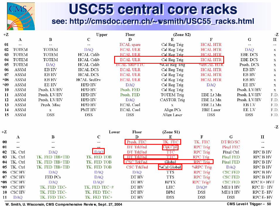
USC55 central core rackssee: http://cmsdoc.cern.ch/~wsmith/USC55_racks.html
USC55 central core racksUSC55 central core rackssee: http://cmsdoc.see: http://cmsdoc.cerncern.ch/~wsmith/USC55_racks.html.ch/~wsmith/USC55_racks.html

W. Smith, U. Wisconsin, CMS Comprehensive Review, Sept. 27, 2004 CMS Level-1 Trigger – 51
Approved Plan for B 904Approved Plan for B 904Approved Plan for B 904

W. Smith, U. Wisconsin, CMS Comprehensive Review, Sept. 27, 2004 CMS Level-1 Trigger – 52
Insuring Successful InstallationInsuring Successful InstallationInsuring Successful InstallationTrigger Component Interfaces
• Each interface specified by a CMS Internal Notesigned by all parties to the individual interface
• Integration tests planned or already done for eachinterface before equipment bought to Point 5
Structured Beam Tests:• Operation of trigger systems with detectors in 25 ns
beam checks synchronization and phase offsetsTests in Electronics Integration Center (B 904)
• Simulate conditions in USC55 as closely as possibleSurface test in SX5:
• Trigger components will participate in the surfacetests & magnet tests in SX5 as permitted by frontend electronics and detector availability

W. Smith, U. Wisconsin, CMS Comprehensive Review, Sept. 27, 2004 CMS Level-1 Trigger – 53
USC55 Trigger Install Schedule – IUSC55 Trigger Install Schedule – IUSC55 Trigger Install Schedule – IInstall/Commission Trig. Crates Dec ‘05 – Apr ‘06
• Tested Trigger Crates installed, re-tested,interconnected, inter-synchronized
• Regional and Global Detector trigger systemsintegrated with each other and Global Trigger
Integrate w/Detector Electronics May ‘06 – Oct ‘06• Cal Trig connected to E/HCAL USC55 electronics• Muon Triggers connected to optical fibers carrying
trigger data from detector• Global Trigger connected to TTC distribution system• Operation with Local DAQ

W. Smith, U. Wisconsin, CMS Comprehensive Review, Sept. 27, 2004 CMS Level-1 Trigger – 54
USC55 Trigger Install Schedule – IIUSC55 Trigger Install Schedule – IIUSC55 Trigger Install Schedule – IIIntegrate w/Central Trig. & DAQ Nov ‘06 – Apr ‘07
• Subset of triggers available to detectors in UXC55• Dedicated testing with individual detectors• Detailed synchronization testing of all systems• Testing with Central DAQ
System Commissioning May ‘07 – Aug ‘07• Full capability of trigger system available• Tests with all detectors and trigger operating
simultaneously together and partitioned• Trigger and DAQ can operate in 8 separate partitions
Ready for Data Taking August, 2007
W. Smith, U. Wisconsin, CMS Comprehensive Review, Sept. 27, 2004 CMS Level-1 Trigger – 55
2Q 04 3Q 04 4Q 04 1Q 05 2Q 05 3Q 05 4Q 05 1Q 06 2Q 06 3Q 06 4Q 06 1Q 07 2Q 07 3Q 07 4Q 07
A M J J A S O N D J F M A M J J A S O N D J F M A M J J A S O N D J F M A M J J A S O N D
Lower CMS
Connect Cables to USC
USC Ready for Crates
UXC Ready for Crates
SCX connected to USC
Ready for LHC Beams
Complete ESRs for CMS Electronics
Complete EIC, Prevessin 904
Testing Electronics in EIC
Install Electronics in USC & UXC
Commission (Self Test)
Commission (Local DAQ)
Commission (Remote DAQ)
Commission Trigger (Stand alone)
Commission Trigger (Sub - Detectors)
Send Triggers to Sub-Detectors
Commission Complete System
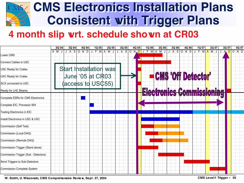
CMS Electronics Installation PlansConsistent with Trigger Plans
CMS Electronics Installation PlansCMS Electronics Installation PlansConsistent with Trigger PlansConsistent with Trigger Plans
4 month slip wrt. schedule shown at CR03
Start Installation wasJune ‘05 at CR03
(access to USC55)

W. Smith, U. Wisconsin, CMS Comprehensive Review, Sept. 27, 2004 CMS Level-1 Trigger – 56
Trigger ConclusionsTrigger ConclusionsTrigger ConclusionsGood Progress on all fronts:
• Prototyping concluding & production starting orunderway
• Integration tests complete or underway• Software being developed• Passed Trigger Electronics System Review May ‘04
Installation:• Time is tight to accomplish the necessary tasks• Steps taken, planning established to meet schedule
• Interfaces: Documents, Integration Tests• Tests: Structured Beam, Surface Tests in SX5• Use of Electronics Integration Center in Prevessin 904• Careful layout and plan for USC55• Flexible system partitioning allows work in parallel