cms 502 hp+ (type 658) component type 001
TRANSCRIPT

Spare-parts catalog
CMS 502 HP+ (Type 658)
Component type 001
E10│E12│E14│E16│E18│E12m.10│E14/12│E6.2│E7.2│ E8.2
Document-no. 271681_01_ENRelease 2017/04


1 Introduction
Imprint
All rights reserved.The utilisation of texts and pictures, also in extracts, without our agreement is unfavourable to the copyright.Our products are being developed further continuously. They are therefore subject to technical modifications. The indications of this catalog are without liability.
©
H. Stoll AG & Co.KG
Stollweg 1
D-72760 Reutlingen, Germany
Phone: +49 (07121) 313-289
Fax: +49 (07121) 313-347
e-mail: [email protected]
Notes for the order
This catalog serves to order spare parts.
It can only be applied to the machine type recorded on the title page.
When ordering spare parts we imperatively ask for the following indications as otherwise a delivery of spare parts is not possible:
1. Type of machine, gauge, no. of machine.
2. Page no., designation, ID, quantity.
Only genuine STOLL spare parts may be used for repairs.
Introduction ...1
Release 2017/04 CMS 502 HP+ (Type 658) 3Document-no. 271681_01_EN Component type 001

1.1 Search helpIn order to make the search of the spare parts easier, the following elements will be used in the spare parts catalog:
Symbol MeaningΣ Indicates an assembly
Position indicator with the position number (X).
Indicates an element of another assembly.
Indicates an assembly which is represented more detailed beside.
Indicates an assembly which is represented on another page more detailed.
Screw torques (z) deviating from the preferential row.
Detail, represented enlarged in the direction of the arrow.
Explosion representation, single elements enlarged.
Indicates a group of parts.
Indicates the left side or view.
Indicates the right-hand side or view.
Indicates a sectional drawing or a view in the viewing direction.
1...Introduction
4 CMS 502 HP+ (Type 658) Release 2017/04
Component type 001 Document-no. 271681_01_EN
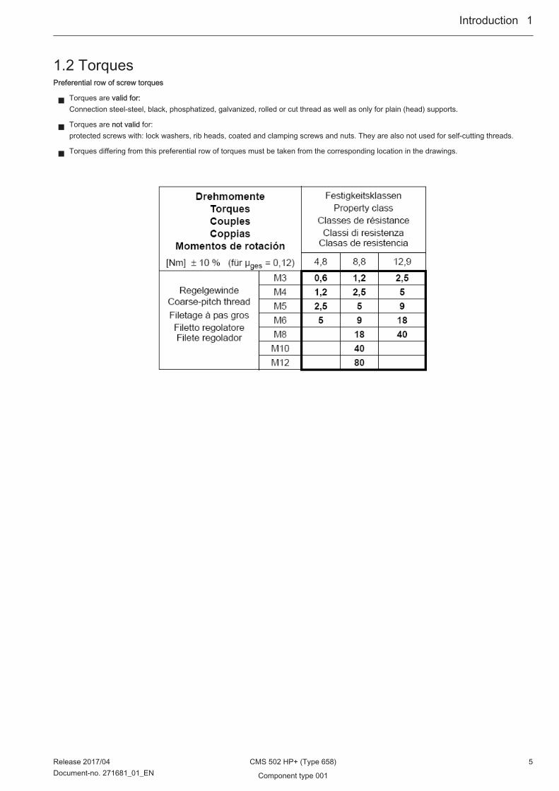
1.2 TorquesPreferential row of screw torques
■ Torques are valid for:Connection steel-steel, black, phosphatized, galvanized, rolled or cut thread as well as only for plain (head) supports.
■ Torques are not valid for:protected screws with: lock washers, rib heads, coated and clamping screws and nuts. They are also not used for self-cutting threads.
■ Torques differing from this preferential row of torques must be taken from the corresponding location in the drawings.
Introduction ...1
Release 2017/04 CMS 502 HP+ (Type 658) 5Document-no. 271681_01_EN Component type 001
1...Introduction
6 CMS 502 HP+ (Type 658) Release 2017/04
Component type 001 Document-no. 271681_01_EN
Table of Contents1 Introduction ....................................................................................................................................................................................................... 3
1.1 Search help ............................................................................................................................................................................................ 41.2 Torques .................................................................................................................................................................................................. 5
2 Carriage drive ................................................................................................................................................................................................. 112.1 Drive .................................................................................................................................................................................................... 12
2.1.1 Motor and belt drive ............................................................................................................................................................. 132.1.2 Tension bearing ................................................................................................................................................................... 14
2.2 Energy chain and carriage driver ......................................................................................................................................................... 15
3 Racking ........................................................................................................................................................................................................... 173.1 Racking drive ....................................................................................................................................................................................... 18
4 Needle beds .................................................................................................................................................................................................... 194.1 Needle bed E12 ................................................................................................................................................................................... 20
4.1.1 Continuation needle bed E12 .............................................................................................................................................. 214.2 Needle bed E14 ................................................................................................................................................................................... 22
4.2.1 Continuation needle bed E14 .............................................................................................................................................. 234.3 Needle bed E16 ................................................................................................................................................................................... 24
4.3.1 Continuation needle bed E16 .............................................................................................................................................. 254.4 Needle bed E18 ................................................................................................................................................................................... 26
4.4.1 Continuation needle bed E18 .............................................................................................................................................. 274.5 Needle bed E6.2 .................................................................................................................................................................................. 28
4.5.1 Continuation needle bed E6.2 ............................................................................................................................................. 294.6 Needle bed E7.2 .................................................................................................................................................................................. 30
4.6.1 Continuation needle bed E7.2 ............................................................................................................................................. 314.7 Needle bed E8.2 .................................................................................................................................................................................. 32
4.7.1 Continuation needle bed E8.2 ............................................................................................................................................. 334.8 Needle bed E6.2 (12m.10) ................................................................................................................................................................... 34
4.8.1 Continuation needle bed E6.2(12m.10) ............................................................................................................................... 354.9 Needle bed E7.2(14/12) ....................................................................................................................................................................... 36
4.9.1 Continuation needle bed E7.2(14/12) .................................................................................................................................. 374.10 Needle beds, connection screws ......................................................................................................................................................... 384.11 Right clamping and cutting bed E10│E12│E14│E6.2│E7.2│E6.2(E12m.10)│E14/12 ........................................................................ 394.12 Right clamping and cutting bed E16│E18│E8.2 .................................................................................................................................. 404.13 Yarn brake at clamping and cutting bed .............................................................................................................................................. 41
5 Carriage .......................................................................................................................................................................................................... 435.1 Overview of carriage ............................................................................................................................................................................ 445.2 Overview of carriage, continuation ...................................................................................................................................................... 455.3 Cam box E12 ...................................................................................................................................................................................... 46
5.3.1 Cams E12 ............................................................................................................................................................................ 475.4 Cam box E14│E14/12 ........................................................................................................................................................................ 48
5.4.1 Cams E14│E14/12 ............................................................................................................................................................. 495.5 Cam box E16│E18 ............................................................................................................................................................................. 50
5.5.1 Cams E16│E18 ................................................................................................................................................................... 515.6 Cam box E12m.10 ............................................................................................................................................................................... 52
5.6.1 Cams E12m.10 .................................................................................................................................................................... 535.7 Cam box E6.2 ...................................................................................................................................................................................... 54
5.7.1 Cams E6.2 ........................................................................................................................................................................... 555.8 Cam box E7.2 ...................................................................................................................................................................................... 56
5.8.1 Cams E7.2 ........................................................................................................................................................................... 575.9 Cam box E8.2 ...................................................................................................................................................................................... 58
5.9.1 Cams E8.2 ........................................................................................................................................................................... 595.10 Carriage assembly ............................................................................................................................................................................... 605.11 Carriage guide ..................................................................................................................................................................................... 615.12 Carriage cover ..................................................................................................................................................................................... 625.13 Yarn Carrier Drive ................................................................................................................................................................................ 635.14 Brush holder ........................................................................................................................................................................................ 64
Table of Contents
Release 2017/04 CMS 502 HP+ (Type 658) 7Document-no. 271681_01_EN Component type 001

5.15 Needle detector ................................................................................................................................................................................... 655.16 Holding-down jack control and slider ................................................................................................................................................... 665.17 Spare parts package carriage guide bar .............................................................................................................................................. 67
6 Main Take-down ............................................................................................................................................................................................. 696.1 Main take-down E10│E12│E14│E6.2(12m.10)│E7.2(14/12)│E6.2│E7.2 ........................................................................................... 706.2 Main take-down E16│E18│E8.2 .......................................................................................................................................................... 716.3 Main take-down on the left ................................................................................................................................................................... 726.4 Main take-down on the right ................................................................................................................................................................ 736.5 Mounting plate on the left and right ..................................................................................................................................................... 746.6 Swivel-mounted bearing ...................................................................................................................................................................... 756.7 Full floating axle on the left and the right ............................................................................................................................................. 766.8 Main take-down in the middle E10│E12│E14│E6.2(12m.10)│E7.2(14/12)│E6.2│E7.2 ..................................................................... 77
6.8.1 Rear take-down roller E10│E12│E14│E6.2(12m.10)│E7.2(14/12)│E6.2│E7.2 .................................................................. 786.9 Main take-down in the middle E16│E18│E8.2 ..................................................................................................................................... 79
6.9.1 Rear take-down roller 16│E18│E8.2 ................................................................................................................................... 806.10 Front take-down roller .......................................................................................................................................................................... 816.11 Angle rail .............................................................................................................................................................................................. 82
7 Auxiliary Take-down ....................................................................................................................................................................................... 837.1 Auxiliary Take-down ............................................................................................................................................................................ 847.2 Auxiliary take-down pre-assembled ..................................................................................................................................................... 85
7.2.1 Right bearing of the auxiliary take-down .............................................................................................................................. 867.2.2 Left bearing of the auxiliary take-down ................................................................................................................................ 87
7.3 Motor .................................................................................................................................................................................................... 887.4 Yarn brake at clamping and cutting bed .............................................................................................................................................. 89
8 Comb Take-down ........................................................................................................................................................................................... 918.1 Comb Take-down ................................................................................................................................................................................ 928.2 Comb take-down on the left ................................................................................................................................................................. 938.3 Comb take-down on the right ............................................................................................................................................................... 94
8.3.1 Drive shaft of comb .............................................................................................................................................................. 958.3.2 Swivel lever comb take-down .............................................................................................................................................. 96
8.4 Comb take-down in the middle ............................................................................................................................................................ 978.4.1 Comb unit ............................................................................................................................................................................ 988.4.2 Switching lever comb take-down ......................................................................................................................................... 99
9 Belt Take-Down ............................................................................................................................................................................................ 1019.1 Belt Take-Down ................................................................................................................................................................................. 1029.2 Belt ..................................................................................................................................................................................................... 1039.3 Drive unit ............................................................................................................................................................................................ 1049.4 Support on the left ............................................................................................................................................................................. 1059.5 Winding guard .................................................................................................................................................................................... 1069.6 Yarn brake ......................................................................................................................................................................................... 107
10 Yarn delivery device ..................................................................................................................................................................................... 10910.1 Yarn guide device ............................................................................................................................................................................. 11010.2 Safety door E10-18 ............................................................................................................................................................................ 11110.3 Yarn Tensioner .................................................................................................................................................................................. 112
10.3.1 Tension axle ...................................................................................................................................................................... 11310.4 Bobbin board ..................................................................................................................................................................................... 11410.5 Yarn guide complete E10-18 ............................................................................................................................................................. 11510.6 Bar unit .............................................................................................................................................................................................. 11610.7 Right friction feed wheel .................................................................................................................................................................... 11710.8 Stopping device on the right .............................................................................................................................................................. 118
11 Operation and control ................................................................................................................................................................................... 11911.1 Input unit ............................................................................................................................................................................................ 12011.2 Starting device ................................................................................................................................................................................... 121
11.2.1 Bearing of the engaging rod .............................................................................................................................................. 12211.3 Shock stop motion ............................................................................................................................................................................. 12311.4 Signal light ......................................................................................................................................................................................... 12411.5 Control of Collecting Area .................................................................................................................................................................. 125
Table of Contents
8 CMS 502 HP+ (Type 658) Release 2017/04
Component type 001 Document-no. 271681_01_EN

11.6 Measuring device ............................................................................................................................................................................... 126
12 Protective device .......................................................................................................................................................................................... 12712.1 Lateral safety doors ........................................................................................................................................................................... 12812.2 Panelling ............................................................................................................................................................................................ 12912.3 Rear panel ......................................................................................................................................................................................... 130
13 Electrical equipment ..................................................................................................................................................................................... 13113.1 Circuit diagram (223) as PDF ............................................................................................................................................................ 13213.2 Trailing cable ..................................................................................................................................................................................... 13413.3 Cable set installation part 1 ............................................................................................................................................................... 13513.4 Cable set installation part 2 ............................................................................................................................................................... 13613.5 Cable set installation part 1, belt take-down ...................................................................................................................................... 13713.6 Cable set installation part 2, belt take-down ...................................................................................................................................... 138
14 Control electronics ........................................................................................................................................................................................ 13914.1 Control cabinet ................................................................................................................................................................................... 140
15 Accessories .................................................................................................................................................................................................. 14115.1 Accessories standard ........................................................................................................................................................................ 14215.2 Carriage of plating yarn carrier .......................................................................................................................................................... 143
16 Special attachment ....................................................................................................................................................................................... 14516.1 Carriage of plating yarn carrier (adjustable) ...................................................................................................................................... 14616.2 Bobbin holder on the right .................................................................................................................................................................. 14716.3 Yarn length measuring device on the left complete ........................................................................................................................... 148
16.3.1 Yarn length measuring device ........................................................................................................................................... 14916.4 Yarn length measuring device on the right complete ......................................................................................................................... 150
16.4.1 Yarn length measuring device on the right ........................................................................................................................ 15116.5 Friction feed wheel on the left ............................................................................................................................................................ 152
16.5.1 Left friction feed wheel ....................................................................................................................................................... 15316.5.2 Stopping device on the left ................................................................................................................................................ 154
16.6 Storage feed wheel MSF-3 complete E10-18 .................................................................................................................................... 15516.7 Sanding Paper Brake ......................................................................................................................................................................... 15616.8 Adjusting plates, Device needle bed complete .................................................................................................................................. 157
Table of Contents
Release 2017/04 CMS 502 HP+ (Type 658) 9Document-no. 271681_01_EN Component type 001

Table of Contents
10 CMS 502 HP+ (Type 658) Release 2017/04
Component type 001 Document-no. 271681_01_EN
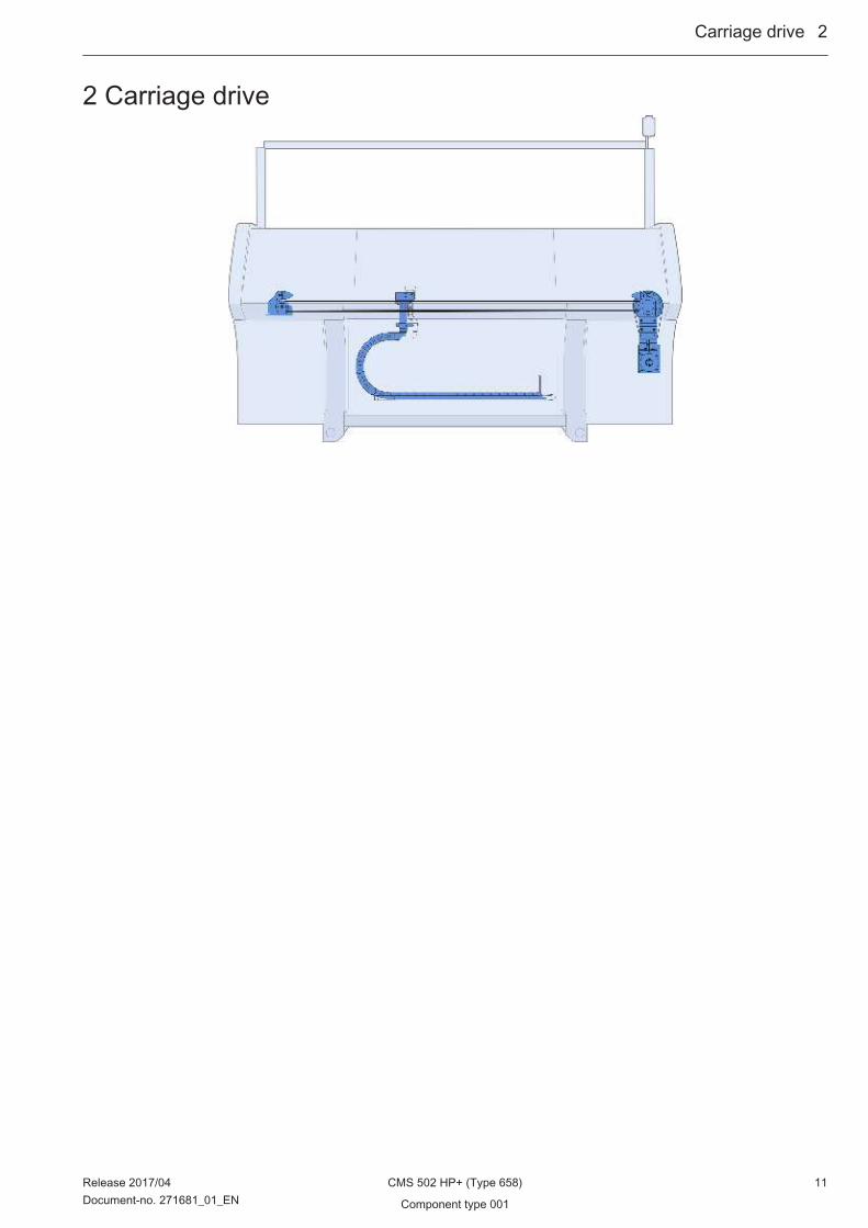
2 Carriage drive
Carriage drive ...2
Release 2017/04 CMS 502 HP+ (Type 658) 11Document-no. 271681_01_EN Component type 001
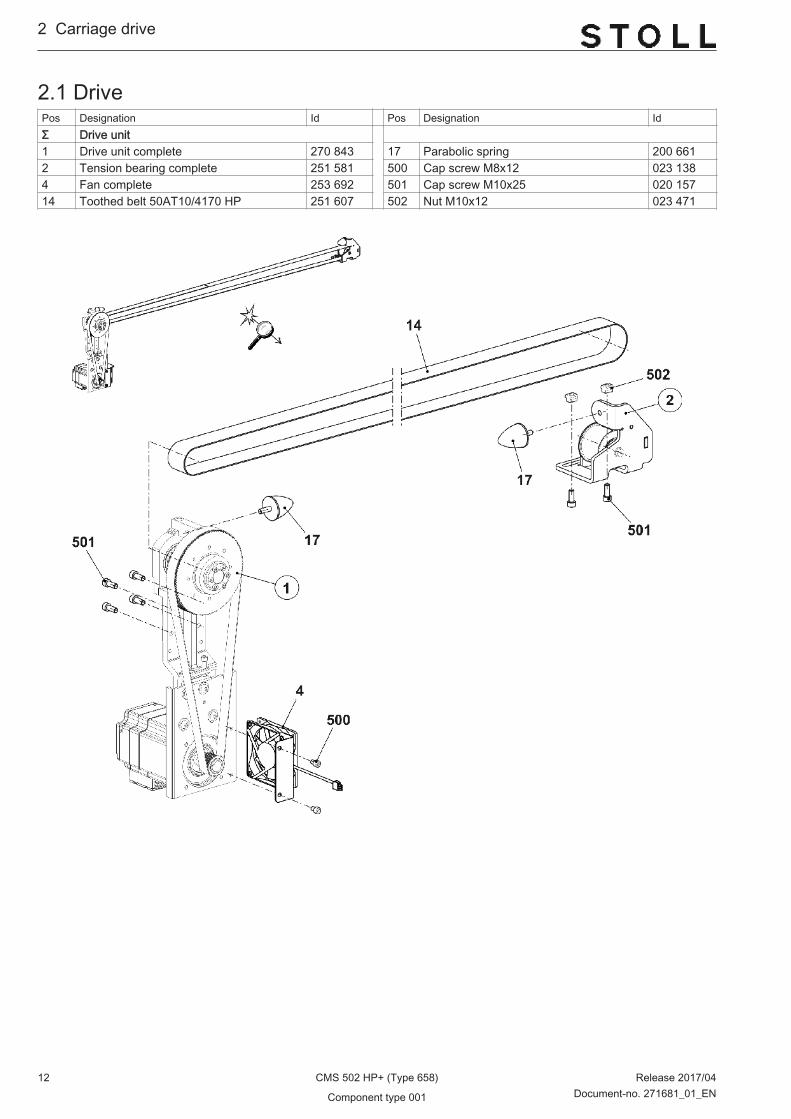
2.1 DrivePos Designation Id Pos Designation IdΣ Drive unit 1 Drive unit complete 270 843 17 Parabolic spring 200 6612 Tension bearing complete 251 581 500 Cap screw M8x12 023 1384 Fan complete 253 692 501 Cap screw M10x25 020 15714 Toothed belt 50AT10/4170 HP 251 607 502 Nut M10x12 023 471
2...Carriage drive
12 CMS 502 HP+ (Type 658) Release 2017/04
Component type 001 Document-no. 271681_01_EN
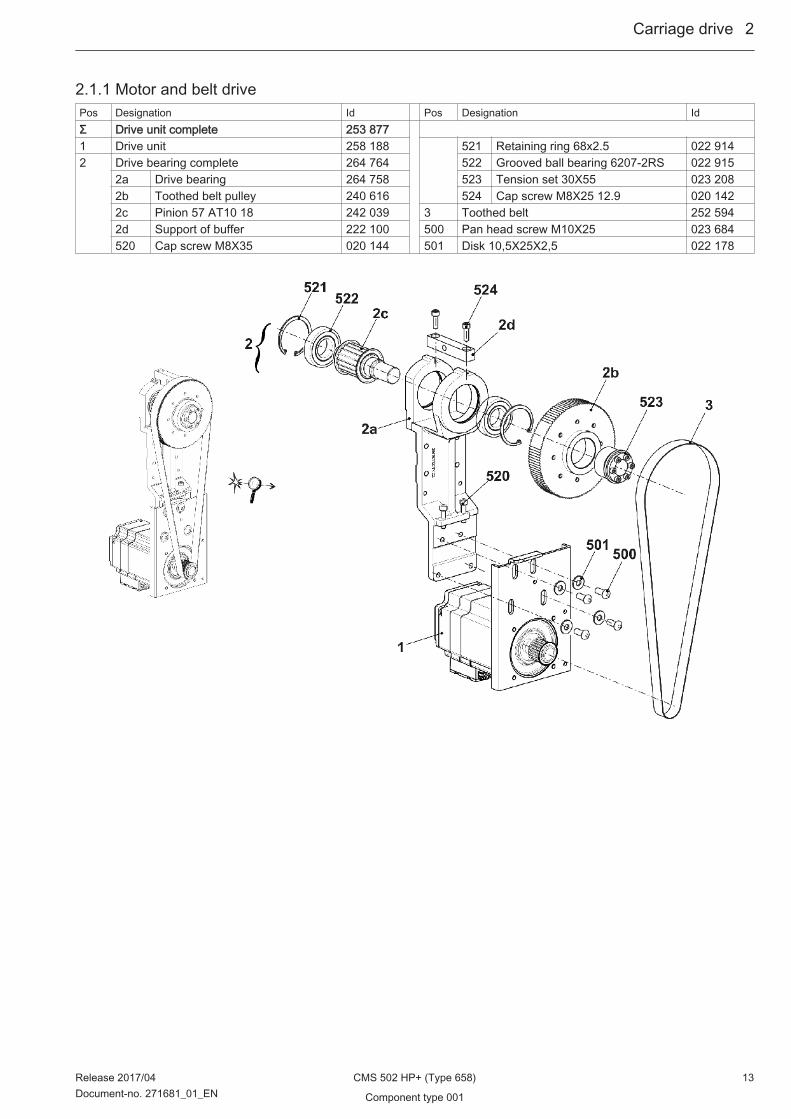
2.1.1 Motor and belt drivePos Designation Id Pos Designation IdΣ Drive unit complete 253 877 1 Drive unit 258 188 521 Retaining ring 68x2.5 022 9142 Drive bearing complete 264 764 522 Grooved ball bearing 6207-2RS 022 915
2a Drive bearing 264 758 523 Tension set 30X55 023 2082b Toothed belt pulley 240 616 524 Cap screw M8X25 12.9 020 1422c Pinion 57 AT10 18 242 039 3 Toothed belt 252 5942d Support of buffer 222 100 500 Pan head screw M10X25 023 684520 Cap screw M8X35 020 144 501 Disk 10,5X25X2,5 022 178
Carriage drive ...2
Release 2017/04 CMS 502 HP+ (Type 658) 13Document-no. 271681_01_EN Component type 001
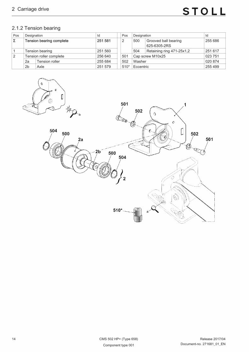
2.1.2 Tension bearingPos Designation Id Pos Designation IdΣ Tension bearing complete 251 581 2 500 Grooved ball bearing
625-6305-2RS255 686
1 Tension bearing 251 560 504 Retaining ring 471-25x1,2 251 6172 Tension roller complete 256 640 501 Cap screw M10x25 023 751
2a Tension roller 255 684 502 Washer 020 8742b Axle 251 579 510* Eccentric 255 499
2...Carriage drive
14 CMS 502 HP+ (Type 658) Release 2017/04
Component type 001 Document-no. 271681_01_EN

2.2 Energy chain and carriage driverPos Designation Id Pos Designation Id1 Energy chain 27 links 253 896 4 43 Clamping plate 252 592501 Cap screw M6x8 023 411 517 Cap screw M8x30 020 1434 Carriage driver complete 265 264 519 Fixing element 026 489
41 Carriage driver 260 689 520 Cap screw M6x8 023 41142 Cable driver 259 287
Carriage drive ...2
Release 2017/04 CMS 502 HP+ (Type 658) 15Document-no. 271681_01_EN Component type 001

2...Carriage drive
16 CMS 502 HP+ (Type 658) Release 2017/04
Component type 001 Document-no. 271681_01_EN

3 Racking
Racking ...3
Release 2017/04 CMS 502 HP+ (Type 658) 17Document-no. 271681_01_EN Component type 001

3.1 Racking drivePos Designation ID Pos Designation IDΣ Racking 1 Racking motor EKC complete 270 086 502 Cap screw M8x25 020 1423 Spindle bearing 267 554 509 Cap screw M6x16 023 1166 Racking strip 264 802 518 Pan head screw M6x10 023 1837 Racking strip on the left 240 696 521 Washer 8,4X20X3 022 1758 Guide strip 206 382 525 Shim 0,03x15x75 023 3959 Card racking limit switch 229 396 526 Shim 0,05x15x75 023 39610 Switch plate 240 722 527 Shim 0,1x15x75 023 39711 Bearing racking motor 264 630 528 Shim 0,2x15x75 023 39813 Toothed belt 150 S 5M 490 229 281 900 Cap screw M6x12 022 79517 Stop screw 221 386 901 Pan head screw M6x10 023 18320 Racking cover plate 264 803 902 Cap screw M8x30 020 143
3...Racking
18 CMS 502 HP+ (Type 658) Release 2017/04
Component type 001 Document-no. 271681_01_EN

4 Needle beds
Needle beds ...4
Release 2017/04 CMS 502 HP+ (Type 658) 19Document-no. 271681_01_EN Component type 001
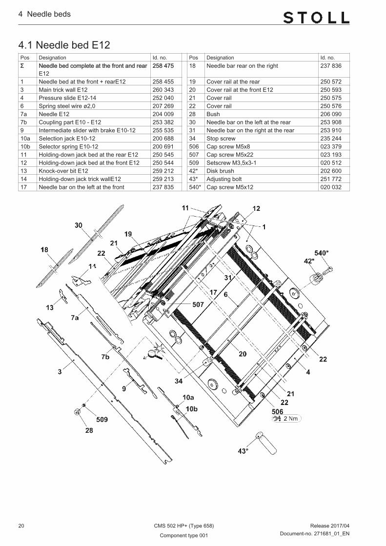
4.1 Needle bed E12Pos Designation Id. no. Pos Designation Id. no.Σ Needle bed complete at the front and rear
E12258 475 18 Needle bar rear on the right 237 836
1 Needle bed at the front + rearE12 258 455 19 Cover rail at the rear 250 5723 Main trick wall E12 260 343 20 Cover rail at the front E12 250 5934 Pressure slide E12-14 252 040 21 Cover rail 250 5756 Spring steel wire ø2,0 207 269 22 Cover rail 250 5767a Needle E12 204 009 28 Bush 206 0907b Coupling part E10 - E12 253 382 30 Needle bar on the left at the rear 253 9089 Intermediate slider with brake E10-12 255 535 31 Needle bar on the right at the rear 253 91010a Selection jack E10-12 200 688 34 Stop screw 235 24410b Selector spring E10-12 200 691 506 Cap screw M5x8 023 37911 Holding-down jack bed at the rear E12 250 545 507 Cap screw M5x22 023 19312 Holding-down jack bed at the front E12 250 544 509 Setscrew M3,5x3-1 020 51213 Knock-over bit E12 259 212 42* Disk brush 202 60014 Holding-down jack trick wallE12 259 213 43* Adjusting bolt 251 77217 Needle bar on the left at the front 237 835 540* Cap screw M5x12 020 032
4...Needle beds
20 CMS 502 HP+ (Type 658) Release 2017/04
Component type 001 Document-no. 271681_01_EN

4.1.1 Continuation needle bed E12Pos Designation Id. no. Pos Designation Id. no.Σ Needle bed complete at the front and
rearE12258 475 505 Cap screw M5x8-8.8 023 154
2 Locating wire ø3,4 208 389 507 Cap screw M5x22 023 1935 Spring steel wire ø0,6 208 388 508 Cap screw M5x12-8.8 022 9436 Spring steel wire ø2,0 207 269 513 Springy thrust piece 023 17715 Limiter on the left E10 - E14 205 764 517 Shim0,05x18,5x34 023 19616 Limiter on the right E10 - E14 205 765 518 Shim0,1x18,5x34 023 19726 Locating wire ø2,8 207 270 519 Shim0,2X18,5X34 023 253
Needle beds ...4
Release 2017/04 CMS 502 HP+ (Type 658) 21Document-no. 271681_01_EN Component type 001
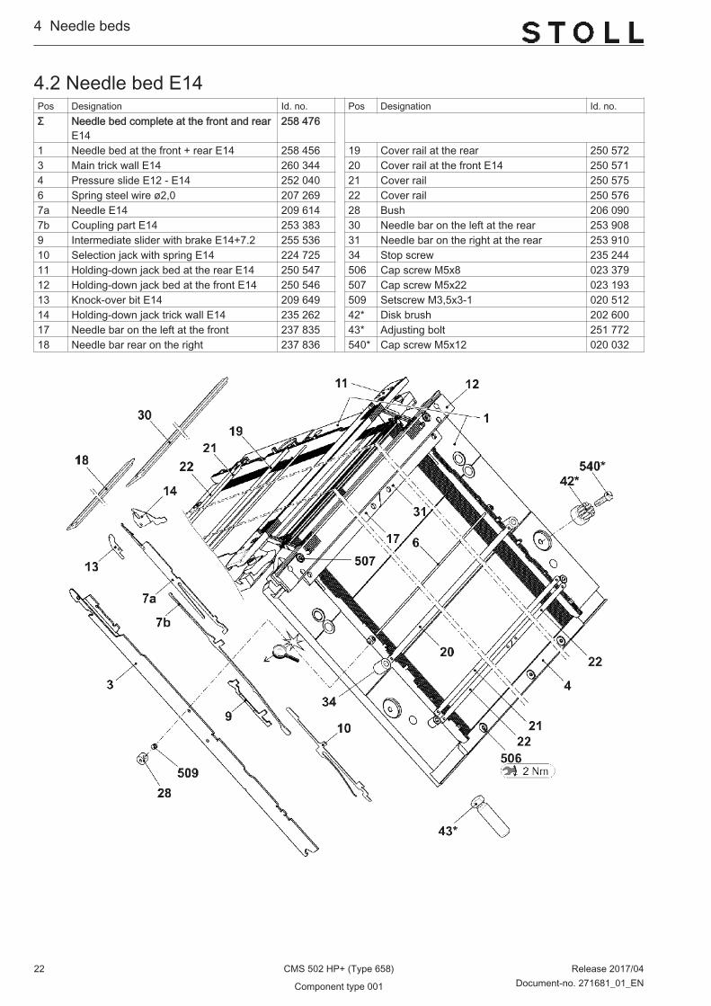
4.2 Needle bed E14Pos Designation Id. no. Pos Designation Id. no.Σ Needle bed complete at the front and rear
E14258 476
1 Needle bed at the front + rear E14 258 456 19 Cover rail at the rear 250 5723 Main trick wall E14 260 344 20 Cover rail at the front E14 250 5714 Pressure slide E12 - E14 252 040 21 Cover rail 250 5756 Spring steel wire ø2,0 207 269 22 Cover rail 250 5767a Needle E14 209 614 28 Bush 206 0907b Coupling part E14 253 383 30 Needle bar on the left at the rear 253 9089 Intermediate slider with brake E14+7.2 255 536 31 Needle bar on the right at the rear 253 91010 Selection jack with spring E14 224 725 34 Stop screw 235 24411 Holding-down jack bed at the rear E14 250 547 506 Cap screw M5x8 023 37912 Holding-down jack bed at the front E14 250 546 507 Cap screw M5x22 023 19313 Knock-over bit E14 209 649 509 Setscrew M3,5x3-1 020 51214 Holding-down jack trick wall E14 235 262 42* Disk brush 202 60017 Needle bar on the left at the front 237 835 43* Adjusting bolt 251 77218 Needle bar rear on the right 237 836 540* Cap screw M5x12 020 032
4...Needle beds
22 CMS 502 HP+ (Type 658) Release 2017/04
Component type 001 Document-no. 271681_01_EN

4.2.1 Continuation needle bed E14Pos Designation Id. no. Pos Designation Id. no.Σ Needle bed complete at the front and
rearE14258 476 505 Cap screw M5x8-8.8 023 154
2 Locating wire ø3,4 208 389 507 Cap screw M5x22 023 1935 Spring steel wire ø0,6 208 388 508 Cap screw M5x12-8.8 022 9436 Spring steel wire ø2,0 207 269 513 Springy thrust piece 023 17715 Limiter on the left E10 - E14 205 764 517 Shim 0,05x18,5x34 023 19616 Limiter on the right E10 - E14 205 765 518 Shim 0,1x18,5x34 023 19726 Locating wire ø2,8 207 270 519 Shim 0,2X18,5X34 023 253
Needle beds ...4
Release 2017/04 CMS 502 HP+ (Type 658) 23Document-no. 271681_01_EN Component type 001

4.3 Needle bed E16Pos Designation Id. no. Pos Designation Id. no.Σ Needle bed complete at the front and
rear completeE16258 477 19 Cover rail at the rear 250 572
1 Needle bed at the front + rear E16 258 457 20 Cover rail at the front E16 250 5873 Main trick wall E16 245 319 21 Cover rail 250 5754 Pressure slide E12-14 252 040 22 Cover rail 250 5766 Spring steel wire ø2,0 207 269 28 Bush 206 0907a Needle E16 232 243 30 Needle bar on the left at the rear 253 9087b Coupling part E16-18 253 384 31 Needle bar on the right at the rear 253 9109 Intermediate slider with brake E16-18 255 537 34 Stop screw 235 24410 Selection jack E16-20 222 265 506 Cap screw M5x8 023 37911 Holding-down jack bed at the rear E16 250 549 507 Cap screw M5x22 023 19312 Holding-down jack bed at the front E16 250 548 509 Setscrew M3,5x3-1 020 51213 Knock-over bit wire position E8.2 261 865 42* Disk brush ø12 202 60014 Holding-down jack E16 264 106 43* Adjusting bolt 251 77217 Needle bar on the left at the front 237 835 510* Cap screw M8x25 020 14218 Needle bar rear on the right 237 836 540* Cap screw M5x12 020 032
4...Needle beds
24 CMS 502 HP+ (Type 658) Release 2017/04
Component type 001 Document-no. 271681_01_EN
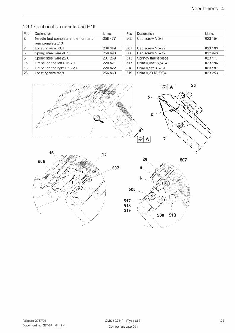
4.3.1 Continuation needle bed E16Pos Designation Id. no. Pos Designation Id. no.Σ Needle bed complete at the front and
rear completeE16258 477 505 Cap screw M5x8 023 154
2 Locating wire ø3,4 208 389 507 Cap screw M5x22 023 1935 Spring steel wire ø0,5 250 690 508 Cap screw M5x12 022 9436 Spring steel wire ø2,0 207 269 513 Springy thrust piece 023 17715 Limiter on the left E16-20 220 821 517 Shim 0,05x18,5x34 023 19616 Limiter on the right E16-20 220 822 518 Shim 0,1x18,5x34 023 19726 Locating wire ø2,8 256 860 519 Shim 0,2X18,5X34 023 253
Needle beds ...4
Release 2017/04 CMS 502 HP+ (Type 658) 25Document-no. 271681_01_EN Component type 001

4.4 Needle bed E18Pos Designation Id. no. Pos Designation Id. no.Σ Needle bed complete at the front and
rear complete E18258 478 19 Cover rail at the rear 250 572
1 Needle bed at the front + rear E18 258 458 20 Cover rail at the front E18 256 8643 Main trick wall E18 251 051 21 Cover rail 250 5754 Pressure slide E12-14 252 040 22 Cover rail 250 5766 Spring steel wire ø2,0 207 269 28 Bush 206 0907a Needle E18 239 527 30 Needle bar on the left at the rear 253 9087b Coupling part E16-18 253 384 31 Needle bar on the right at the rear 253 9109 Intermediate slider with brake E16-18 255 537 34 Stop screw 235 24410 Selection jack E16-20 222 265 506 Cap screw M5x8 023 37911 Holding-down jack bed at the rear E18 250 551 507 Cap screw M5x22 023 19312 Holding-down jack bed at the front E18 250 550 509 Setscrew M3,5x3-1 020 51213 Knock-over bit wire position 0,8 mm E18 263 927 42* Disk brush ø12 202 60014 Holding-down jack E18 264 107 43* Adjusting bolt 251 77217 Needle bar on the left at the front 237 835 510* Cap screw M8x25 020 14218 Needle bar rear on the right 237 836 540* Cap screw M5x12 020 032
4...Needle beds
26 CMS 502 HP+ (Type 658) Release 2017/04
Component type 001 Document-no. 271681_01_EN

4.4.1 Continuation needle bed E18Pos Designation Id. no. Pos Designation Id. no.Σ Needle bed complete at the front and
rear completeE18258 478 505 Cap screw M5x8 023 154
2 Locating wire ø3,4 208 389 507 Cap screw M5x22 023 1935 Spring steel wire ø0,5 250 690 508 Cap screw M5x12-8.8 022 9436 Spring steel wire ø2,0 207 269 513 Springy thrust piece 023 17715 Limiter on the left E16-20 220 821 517 Shim 0,05x18,5x34 023 19616 Limiter on the right E16-20 220 822 518 Shim 0,1x18,5x34 023 19726 Locating wire ø2,8 256 860 519 Shim 0,2X18,5X34 023 253
Needle beds ...4
Release 2017/04 CMS 502 HP+ (Type 658) 27Document-no. 271681_01_EN Component type 001

4.5 Needle bed E6.2Pos Designation Id. no. Pos Designation Id. no.Σ Needle bed complete at the front and rear
E6.2258 481 18 Cover rail at the front E12 250 593
1 Needle bed at the front + rearE12 258 455 19 Cover rail 250 5752 Holding-down jack bed at the front E6.2 250 917 20 Cover rail 250 5763 Holding-down jack bed at the rear E6.2 250 918 23 Needle bar on the left at the front 237 8354 Main trick wall E12 260 343 24 Needle bar rear on the right 237 8365 Pressure slide E12-14 252 040 25 Bush 206 0908 Spring steel wire ø2,0 207 269 27 Stop screw 235 2449a Needle E6.2 207 349 30 Needle bar on the left at the rear 253 9089b Coupling part E10 - E12 253 382 31 Needle bar on the right at the rear 253 91011 Intermediate slider with brake E10-12 255 535 502 Cap screw M5x8 023 37912a Selection jack E10-12 200 688 503 Cap screw M5x22 023 19312b Selector spring E10-12 200 691 505 Setscrew M3,5x3-1 020 51213 Knock-over bit E12 259 212 42* Disk brush 202 60014 Holding-down jack trick wallE12 259 213 43* Adjusting bolt 251 77217 Cover rail at the rear 250 572 540* Cap screw M5x12 020 032
4...Needle beds
28 CMS 502 HP+ (Type 658) Release 2017/04
Component type 001 Document-no. 271681_01_EN

4.5.1 Continuation needle bed E6.2Pos Designation Id. no. Pos Designation Id. no.Σ Needle bed complete at the front and
rearE6.2258 481 501 Cap screw M5x8-8.8 023 154
6 Locating wire ø3,4 208 389 503 Cap screw M5x22 023 1937 Spring steel wire ø0,6 208 388 504 Cap screw M5x12-8.8 022 9438 Spring steel wire ø2,0 207 269 507 Springy thrust piece 023 17715 Limiter on the left E10 - E14 205 764 510 Shim0,05x18,5x34 023 19616 Limiter on the right E10 - E14 205 765 511 Shim0,1x18,5x34 023 19727 Locating wire ø2,8 207 270 512 Shim0,2X18,5X34 023 253
Needle beds ...4
Release 2017/04 CMS 502 HP+ (Type 658) 29Document-no. 271681_01_EN Component type 001

4.6 Needle bed E7.2Pos Designation Id. no. Pos Designation Id. no.Σ Needle bed complete at the front and rear
E7.2258 482
1 Needle bed at the front + rear E14 258 456 19 Cover rail 250 5752 Holding-down jack bed at the front E7.2 250 919 20 Cover rail 250 5763 Holding-down jack bed at the rear E7.2 250 920 23 Needle bar on the left at the front 237 8354 Main trick wall E14 260 344 24 Needle bar rear on the right 237 8365 Pressure slide E12-14 252 040 25 Bush 206 0908 Spring steel wire ø2,0 207 269 27 Stop screw 235 2449a Needle E7.2 225 230 30 Needle bar on the left at the rear 253 9089b Coupling part E14 253 383 31 Needle bar on the right at the rear 253 91010 Selection jack with spring E14 224 725 502 Cap screw M5x8 023 37911 Intermediate slider with brake E14 255 536 503 Cap screw M5x22 023 19313 Knock-over bit 256 912 505 Setscrew M3,5x3-1 020 51214 Holding-down jack trick wall E7.2 258 396 42* Disk brush 202 60017 Cover rail at the rear 250 572 43* Adjusting bolt 251 77218 Cover rail at the front E14 250 571 540* Cap screw M5x12 020 032
4...Needle beds
30 CMS 502 HP+ (Type 658) Release 2017/04
Component type 001 Document-no. 271681_01_EN

4.6.1 Continuation needle bed E7.2Pos Designation Id. no. Pos Designation Id. no.Σ Needle bed complete at the front and
rearE7.2258 482 501 Cap screw M5x8-8.8 023 154
6 Locating wire ø3,4 208 389 503 Cap screw M5x22 023 1937 Spring steel wire ø0,6 208 388 504 Cap screw M5x12-8.8 022 9438 Spring steel wire ø2,0 207 269 507 Springy thrust piece 023 17715 Limiter on the left E10 - E14 205 764 510 Shim0,05x18,5x34 023 19616 Limiter on the right E10 - E14 205 765 511 Shim0,1x18,5x34 023 19727 Locating wire ø2,8 207 270 512 Shim0,2X18,5X34 023 253
Needle beds ...4
Release 2017/04 CMS 502 HP+ (Type 658) 31Document-no. 271681_01_EN Component type 001
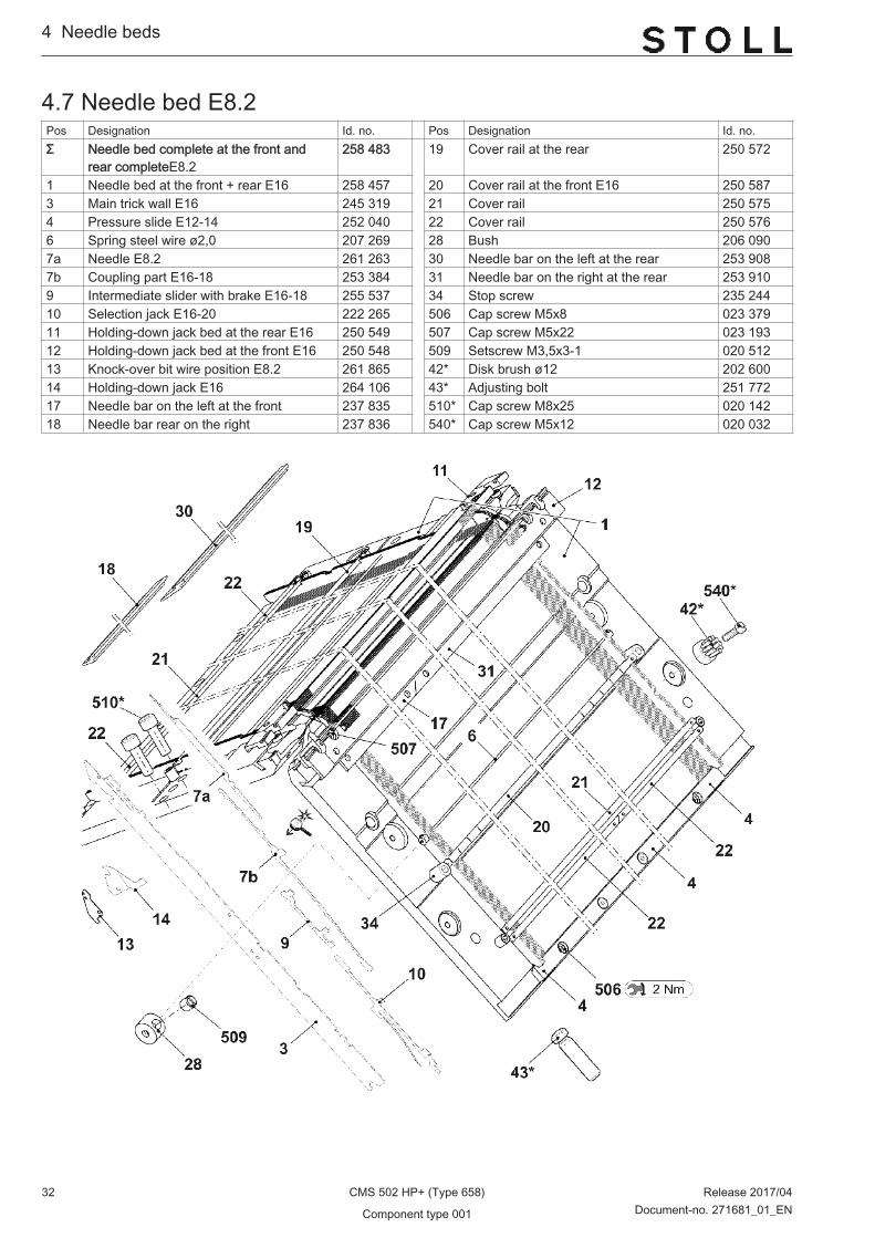
4.7 Needle bed E8.2Pos Designation Id. no. Pos Designation Id. no.Σ Needle bed complete at the front and
rear completeE8.2258 483 19 Cover rail at the rear 250 572
1 Needle bed at the front + rear E16 258 457 20 Cover rail at the front E16 250 5873 Main trick wall E16 245 319 21 Cover rail 250 5754 Pressure slide E12-14 252 040 22 Cover rail 250 5766 Spring steel wire ø2,0 207 269 28 Bush 206 0907a Needle E8.2 261 263 30 Needle bar on the left at the rear 253 9087b Coupling part E16-18 253 384 31 Needle bar on the right at the rear 253 9109 Intermediate slider with brake E16-18 255 537 34 Stop screw 235 24410 Selection jack E16-20 222 265 506 Cap screw M5x8 023 37911 Holding-down jack bed at the rear E16 250 549 507 Cap screw M5x22 023 19312 Holding-down jack bed at the front E16 250 548 509 Setscrew M3,5x3-1 020 51213 Knock-over bit wire position E8.2 261 865 42* Disk brush ø12 202 60014 Holding-down jack E16 264 106 43* Adjusting bolt 251 77217 Needle bar on the left at the front 237 835 510* Cap screw M8x25 020 14218 Needle bar rear on the right 237 836 540* Cap screw M5x12 020 032
4...Needle beds
32 CMS 502 HP+ (Type 658) Release 2017/04
Component type 001 Document-no. 271681_01_EN
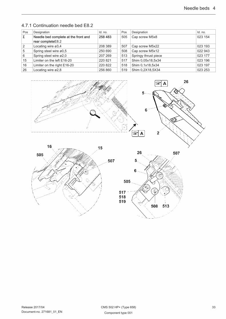
4.7.1 Continuation needle bed E8.2Pos Designation Id. no. Pos Designation Id. no.Σ Needle bed complete at the front and
rear completeE8.2258 483 505 Cap screw M5x8 023 154
2 Locating wire ø3,4 208 389 507 Cap screw M5x22 023 1935 Spring steel wire ø0,5 250 690 508 Cap screw M5x12 022 9436 Spring steel wire ø2,0 207 269 513 Springy thrust piece 023 17715 Limiter on the left E16-20 220 821 517 Shim 0,05x18,5x34 023 19616 Limiter on the right E16-20 220 822 518 Shim 0,1x18,5x34 023 19726 Locating wire ø2,8 256 860 519 Shim 0,2X18,5X34 023 253
Needle beds ...4
Release 2017/04 CMS 502 HP+ (Type 658) 33Document-no. 271681_01_EN Component type 001
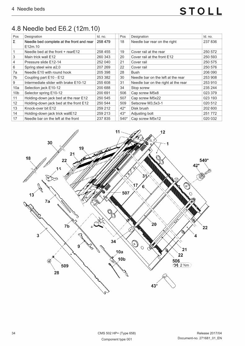
4.8 Needle bed E6.2 (12m.10)Pos Designation Id. no. Pos Designation Id. no.Σ Needle bed complete at the front and rear
E12m.10258 479 18 Needle bar rear on the right 237 836
1 Needle bed at the front + rearE12 258 455 19 Cover rail at the rear 250 5723 Main trick wall E12 260 343 20 Cover rail at the front E12 250 5934 Pressure slide E12-14 252 040 21 Cover rail 250 5756 Spring steel wire ø2,0 207 269 22 Cover rail 250 5767a Needle E10 with round hook 205 398 28 Bush 206 0907b Coupling part E10 - E12 253 382 30 Needle bar on the left at the rear 253 9089 Intermediate slider with brake E10-12 255 608 31 Needle bar on the right at the rear 253 91010a Selection jack E10-12 200 688 34 Stop screw 235 24410b Selector spring E10-12 200 691 506 Cap screw M5x8 023 37911 Holding-down jack bed at the rear E12 250 545 507 Cap screw M5x22 023 19312 Holding-down jack bed at the front E12 250 544 509 Setscrew M3,5x3-1 020 51213 Knock-over bit E12 259 212 42* Disk brush 202 60014 Holding-down jack trick wallE12 259 213 43* Adjusting bolt 251 77217 Needle bar on the left at the front 237 835 540* Cap screw M5x12 020 032
4...Needle beds
34 CMS 502 HP+ (Type 658) Release 2017/04
Component type 001 Document-no. 271681_01_EN

4.8.1 Continuation needle bed E6.2(12m.10)Pos Designation Id. no. Pos Designation Id. no.Σ Needle bed complete at the front and
rearE12m.10258 479 505 Cap screw M5x8-8.8 023 154
2 Locating wire ø3,4 208 389 507 Cap screw M5x22 023 1935 Spring steel wire ø0,6 208 388 508 Cap screw M5x12-8.8 022 9436 Spring steel wire ø2,0 207 269 513 Springy thrust piece 023 17715 Limiter on the left E10 - E14 205 764 517 Shim0,05x18,5x34 023 19616 Limiter on the right E10 - E14 205 765 518 Shim0,1x18,5x34 023 19726 Locating wire ø2,8 207 270 519 Shim0,2X18,5X34 023 253
Needle beds ...4
Release 2017/04 CMS 502 HP+ (Type 658) 35Document-no. 271681_01_EN Component type 001

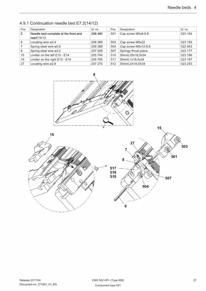
4.9 Needle bed E7.2(14/12)Pos Designation Id. no. Pos Designation Id. no.Σ Needle bed complete at the front and rear
E14/12258 480
1 Needle bed at the front + rear E14 258 456 19 Cover rail 250 5752 Holding-down jack bed at the front E14 250 546 20 Cover rail 250 5763 Holding-down jack bed at the rear E14 250 547 23 Needle bar on the left at the front 237 8354 Main trick wall E14 260 344 24 Needle bar rear on the right 237 8365 Pressure slide E12-14 252 040 25 Bush 206 0908 Spring steel wire ø2,0 207 269 27 Stop screw 235 2449a Needle E14/12 227 756 30 Needle bar on the left at the rear 253 9089b Coupling part E14 253 383 31 Needle bar on the right at the rear 253 91011 Intermediate slider with brake E14 255 536 502 Cap screw M5x8 023 37912 Selection jack with spring E14 224 725 503 Cap screw M5x22 023 19313 Knock-over bit E14 209 649 505 Setscrew M3,5x3-1 020 51214 Holding-down jack trick wall E14 235 262 42* Disk brush 202 60017 Cover rail at the rear 250 572 43* Adjusting bolt 251 77218 Cover rail at the front E14 250 571 540* Cap screw M5x12 020 032
4...Needle beds
36 CMS 502 HP+ (Type 658) Release 2017/04
Component type 001 Document-no. 271681_01_EN
4.9.1 Continuation needle bed E7.2(14/12)Pos Designation Id. no. Pos Designation Id. no.Σ Needle bed complete at the front and
rearE14/12258 480 501 Cap screw M5x8-8.8 023 154
6 Locating wire ø3,4 208 389 503 Cap screw M5x22 023 1937 Spring steel wire ø0,6 208 388 504 Cap screw M5x12-8.8 022 9438 Spring steel wire ø2,0 207 269 507 Springy thrust piece 023 17715 Limiter on the left E10 - E14 205 764 510 Shim0,05x18,5x34 023 19616 Limiter on the right E10 - E14 205 765 511 Shim0,1x18,5x34 023 19727 Locating wire ø2,8 207 270 512 Shim0,2X18,5X34 023 253
Needle beds ...4
Release 2017/04 CMS 502 HP+ (Type 658) 37Document-no. 271681_01_EN Component type 001

4.10 Needle beds, connection screwsPos Designation Id. no. Pos Designation Id. no.Σ Connection screws 500 Cap screw M8x25 020 142
4...Needle beds
38 CMS 502 HP+ (Type 658) Release 2017/04
Component type 001 Document-no. 271681_01_EN
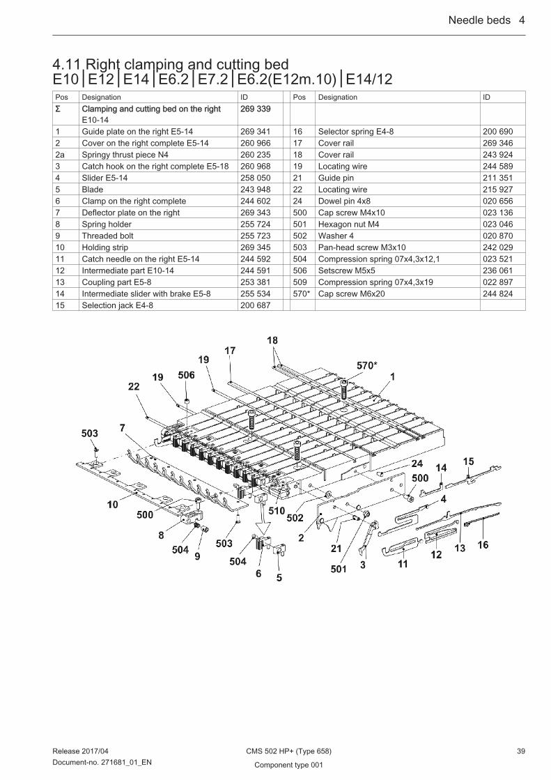
4.11 Right clamping and cutting bedE10│E12│E14│E6.2│E7.2│E6.2(E12m.10)│E14/12Pos Designation ID Pos Designation IDΣ Clamping and cutting bed on the right
E10-14269 339
1 Guide plate on the right E5-14 269 341 16 Selector spring E4-8 200 6902 Cover on the right complete E5-14 260 966 17 Cover rail 269 3462a Springy thrust piece N4 260 235 18 Cover rail 243 9243 Catch hook on the right complete E5-18 260 968 19 Locating wire 244 5894 Slider E5-14 258 050 21 Guide pin 211 3515 Blade 243 948 22 Locating wire 215 9276 Clamp on the right complete 244 602 24 Dowel pin 4x8 020 6567 Deflector plate on the right 269 343 500 Cap screw M4x10 023 1368 Spring holder 255 724 501 Hexagon nut M4 023 0469 Threaded bolt 255 723 502 Washer 4 020 87010 Holding strip 269 345 503 Pan-head screw M3x10 242 02911 Catch needle on the right E5-14 244 592 504 Compression spring 07x4,3x12,1 023 52112 Intermediate part E10-14 244 591 506 Setscrew M5x5 236 06113 Coupling part E5-8 253 381 509 Compression spring 07x4,3x19 022 89714 Intermediate slider with brake E5-8 255 534 570* Cap screw M6x20 244 82415 Selection jack E4-8 200 687
Needle beds ...4
Release 2017/04 CMS 502 HP+ (Type 658) 39Document-no. 271681_01_EN Component type 001

4.12 Right clamping and cutting bed E16│E18│E8.2Pos Designation ID Pos Designation IDΣ Clamping and cutting bed on the right
E16-18269 675
1 Guide plate on the right E16-18 269 676 16 Selector spring E10-12 200 6912 Cover on the right complete E16-18 259 406 17 Cover rail 243 9232a Springy thrust piece N4 260 235 18 Cover rail 243 9243 Catch hook on the right complete E10-18 259 310 19 Locating wire 243 9254 Slider E16-18 259 309 21 Guide pin 211 3515 Blade 243 948 22 Locating wire 215 9276 Clamp on the right complete 244 602 23 Locating wire 244 5897 Deflector plate on the right 269 343 24 Dowel pin 4x8 020 6568 Spring holder 255 724 500 Cap screw M4x10 023 1369 Threaded bolt 255 723 501 Hexagon nut M4 023 04610 Holding strip 269 345 502 Washer 4 020 87011 Catch needle on the right E16-18 244 739 503 Pan-head screw M3x10 242 02912 Intermediate part 244 741 504 Compression spring 07x4,3x12,1 023 52113 Coupling part E10-12 253 382 506 Setscrew M5x5 236 06114 Intermediate slider with brake E10-12 255 535 509 Compression spring 07x4,3x19 022 89715 Selection jack E10-12 200 688 570* Cap screw M6x20 244 824
4...Needle beds
40 CMS 502 HP+ (Type 658) Release 2017/04
Component type 001 Document-no. 271681_01_EN

4.13 Yarn brake at clamping and cutting bedPos Designation Id Pos Designation IdΣ R Yarn brake on the right 256 715 3 Cover on the right 256 714 2 Test clamping plate 256 7131 Leaf spring 256 712 500 Cap screw M4x6 023 067
Needle beds ...4
Release 2017/04 CMS 502 HP+ (Type 658) 41Document-no. 271681_01_EN Component type 001

4...Needle beds
42 CMS 502 HP+ (Type 658) Release 2017/04
Component type 001 Document-no. 271681_01_EN
5 Carriage
Carriage ...5
Release 2017/04 CMS 502 HP+ (Type 658) 43Document-no. 271681_01_EN Component type 001

5.1 Overview of carriagePos Designation Id. no. Pos Designation Id. no.Σ Carriage complete 1 Cam box complete
E12 269 856 E12 269 847E14│E14/12 269 857 E14│E14/12 269 848E16│E18 269 858 E16│E18 269 849E12m.10 269 859 E12m.10 269 850E6.2 269 860 E6.2 269 851E7.2 269 861 E7.2 269 852E8.2 269 862 E8.2 269 853
2 Holding-down jack control completeE12-14, 6.2
256 307 4 Selection system complete E14 (E7.2) 229 300
Holding-down jack control completeE16-18
256 308 Selection system complete E16-18 (E8.2) 220 114
Holding-down jack control complete E7.2 256 309 7 Motor unit ATM complete 251 827Holding-down jack control complete E8.2 256 310 7a Gear rack at the top complete 251 817
3 Carriage assembly 2 cam boxes complete5 inches 502
258 453 7b Gear rack at the bottom complete 251 818
4 Selection system complete E10-12 (E6.2) 216 219 500 Cap screw M4x35 023 550 506 Cap screw M4x20 023 290
5...Carriage
44 CMS 502 HP+ (Type 658) Release 2017/04
Component type 001 Document-no. 271681_01_EN

5.2 Overview of carriage, continuationPos Designation Id. no. Pos Designation Id. no.Σ Carriage complete 1 FF driving outside complete 268 845 9 Cable connection YC output stage OKC 240 6513 Wiper felt 241 411 10 Cover plate at the bottom 251 1274 Bolts 212 392 11 Needle detector pre-assembled E10-18 256 4755 Cover plate at the top 250 594 12 Sinker opener complete 256 6236 Cover plate at the bottom 250 595 30* Distributor 2S-5Z OKC3 255 695
Carriage ...5
Release 2017/04 CMS 502 HP+ (Type 658) 45Document-no. 271681_01_EN Component type 001

5.3 Cam box E12 Pos Designation Id. no. Pos Designation Id. no.Σ Cam box set complete E12 269 847 1 Cam plate E10-18 269 843 37 d Circlip 023 56522 Stay bolt 254 839 e Disk 259 64723 Guide of pressure cam complete 253 480 f Washer 022 89334 Loop sinking cam on the left complete
E12-14254 248 38 Slider pressure cam complete 251 834
35 Loop sinking cam on the right completeE12-14
254 249 43 Holding piece 251 828
36 Rod guide on the left complete 252 662 503 Cap screw M3x6 022 58937 Rod guide on the right complete 252 663 505 Shim 0,5x12x75 236 654
a Rod guide part 258 148 509 Pan head screw M3x4 023 142b Spring rod 252 661 511 Shim 0,03x8x28 023 452c Compression spring 257 082 512 Shim 0,05x8x28 023 020
5...Carriage
46 CMS 502 HP+ (Type 658) Release 2017/04
Component type 001 Document-no. 271681_01_EN

5.3.1 Cams E12Pos Designation Id Pos Designation Id2 Entry cam on the left at the top E10-18 266 707 21 Selection cam E10-18 251 8753 Entry cam on the right at the top E10-18 266 708 24 Tuck pressure cam 253 8284 Entry cam at the top E10-18 256 689 25 Limiting cam E12-14 252 5225 Knitting position cam E10-14│E6.2│E7.2 255 021 26 Pointer E10 251 9946 Plate on the left E10-18 255 389 27 Screw 210 3357 Plate on the right E10-18 255 390 28 Stitch cam on the left E10-14│E7.2 254 3318 Entry cam on the left E10-18 255 391 29 Stitch cam on the right E10-14│E7.2 254 3329 Entry cam on the right E10-18 255 392 30 Tuck limiting cam E12-14 254 29810 Pressure strip E10-14 255 540 31 Raising cam plate E10-18 251 99211 Cam guide at the top E10-18 258 161 32 Receiving cam E10│E12 251 99712 Cam guide E10-18 255 541 33 Raising cam without split-stitch E10│E12 254 33413 Cam on the left E10-18 255 613 Raising cam with split-stitch E10│E12 254 33514 Cam at the right E10-18 255 614 39 Cam at the right E10-18 259 76915 Limiting cam on the left 264 051 40 Knitting position cam on the left
E10-14│E6.2│E7.2255 022
16 Limiting cam on the right 264 052 41 Knitting position cam on the rightE10-14│E6.2│E7.2
255 023
17 Cam on the left E10-18 259 768 50 Delivery pressure cam 253 83818 Cam E10-18 269 831 51 Offering cam 210 18519 Selection cam on the left E10-18 251 876 500 Cap screw M4x8 020 09120 Selection cam on the right E10-18 251 877 510 Cap screw M3x8 020 081
Carriage ...5
Release 2017/04 CMS 502 HP+ (Type 658) 47Document-no. 271681_01_EN Component type 001
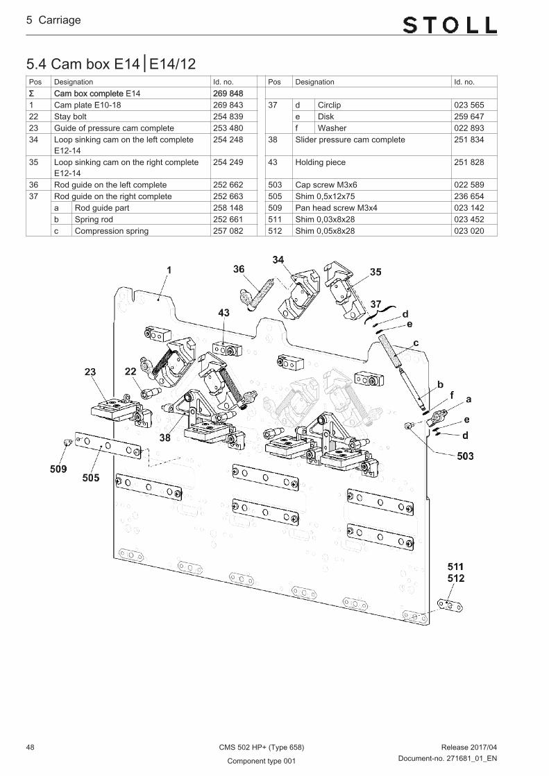
5.4 Cam box E14│E14/12 Pos Designation Id. no. Pos Designation Id. no.Σ Cam box complete E14 269 848 1 Cam plate E10-18 269 843 37 d Circlip 023 56522 Stay bolt 254 839 e Disk 259 64723 Guide of pressure cam complete 253 480 f Washer 022 89334 Loop sinking cam on the left complete
E12-14254 248 38 Slider pressure cam complete 251 834
35 Loop sinking cam on the right completeE12-14
254 249 43 Holding piece 251 828
36 Rod guide on the left complete 252 662 503 Cap screw M3x6 022 58937 Rod guide on the right complete 252 663 505 Shim 0,5x12x75 236 654
a Rod guide part 258 148 509 Pan head screw M3x4 023 142b Spring rod 252 661 511 Shim 0,03x8x28 023 452c Compression spring 257 082 512 Shim 0,05x8x28 023 020
5...Carriage
48 CMS 502 HP+ (Type 658) Release 2017/04
Component type 001 Document-no. 271681_01_EN

5.4.1 Cams E14│E14/12 Pos Designation Id Pos Designation Id2 Entry cam on the left at the top E10-18 266 707 21 Selection cam E10-18 251 8753 Entry cam on the right at the top
E10-18266 708 24 Tuck pressure cam 253 828
4 Entry cam at the top E10-18 256 689 25 Limiting cam E12-14 252 5225 Knitting position cam
E10-14│E6.2│E7.2255 021 26 Pointer E10 251 994
6 Plate on the left E10-18 255 389 27 Screw 210 3357 Plate on the right E10-18 255 390 28 Stitch cam on the left E10-14│E7.2 254 3318 Entry cam on the left E10-18 255 391 29 Stitch cam on the right E10-14│E7.2 254 3329 Entry cam on the right E10-18 255 392 30 Tuck limiting cam E12│E14 254 29810 Pressure strip E10-14 255 540 31 Raising cam plate E10-18 251 99211 Cam guide at the top E10-18 258 161 32 Receiving cam E14 252 60712 Cam guide E10-18 255 541 33 Raising cam without split-stitch E14 254 33613 Cam on the left E10-18 255 613 Raising cam with split-stitch E14 254 33714 Cam at the right E10-18 255 614 39 Cam at the right E10-18 259 76915 Limiting cam on the left 264 051 40 Knitting position cam on the left
E10-14│E6.2│E7.2255 022
16 Limiting cam on the right 264 052 41 Knitting position cam on the rightE10-14│E6.2│E7.2
255 023
17 Cam on the left E10-18 259 768 50 Delivery pressure cam 253 83818 Cam E10-18 269 831 51 Offering cam 210 18519 Selection cam on the left E10-18 251 876 500 Cap screw M4x8 020 09120 Selection cam on the right E10-18 251 877 510 Cap screw M3x8 020 081
Carriage ...5
Release 2017/04 CMS 502 HP+ (Type 658) 49Document-no. 271681_01_EN Component type 001
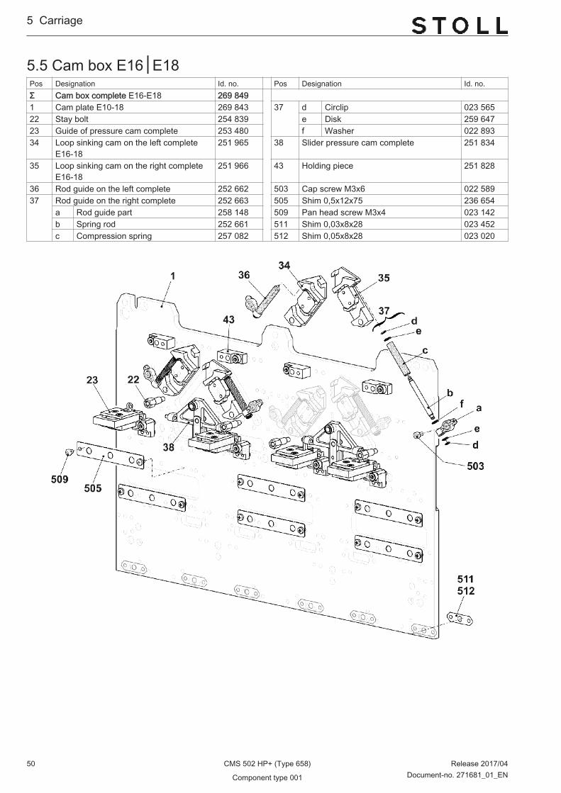
5.5 Cam box E16│E18 Pos Designation Id. no. Pos Designation Id. no.Σ Cam box complete E16-E18 269 849 1 Cam plate E10-18 269 843 37 d Circlip 023 56522 Stay bolt 254 839 e Disk 259 64723 Guide of pressure cam complete 253 480 f Washer 022 89334 Loop sinking cam on the left complete
E16-18251 965 38 Slider pressure cam complete 251 834
35 Loop sinking cam on the right completeE16-18
251 966 43 Holding piece 251 828
36 Rod guide on the left complete 252 662 503 Cap screw M3x6 022 58937 Rod guide on the right complete 252 663 505 Shim 0,5x12x75 236 654
a Rod guide part 258 148 509 Pan head screw M3x4 023 142b Spring rod 252 661 511 Shim 0,03x8x28 023 452c Compression spring 257 082 512 Shim 0,05x8x28 023 020
5...Carriage
50 CMS 502 HP+ (Type 658) Release 2017/04
Component type 001 Document-no. 271681_01_EN
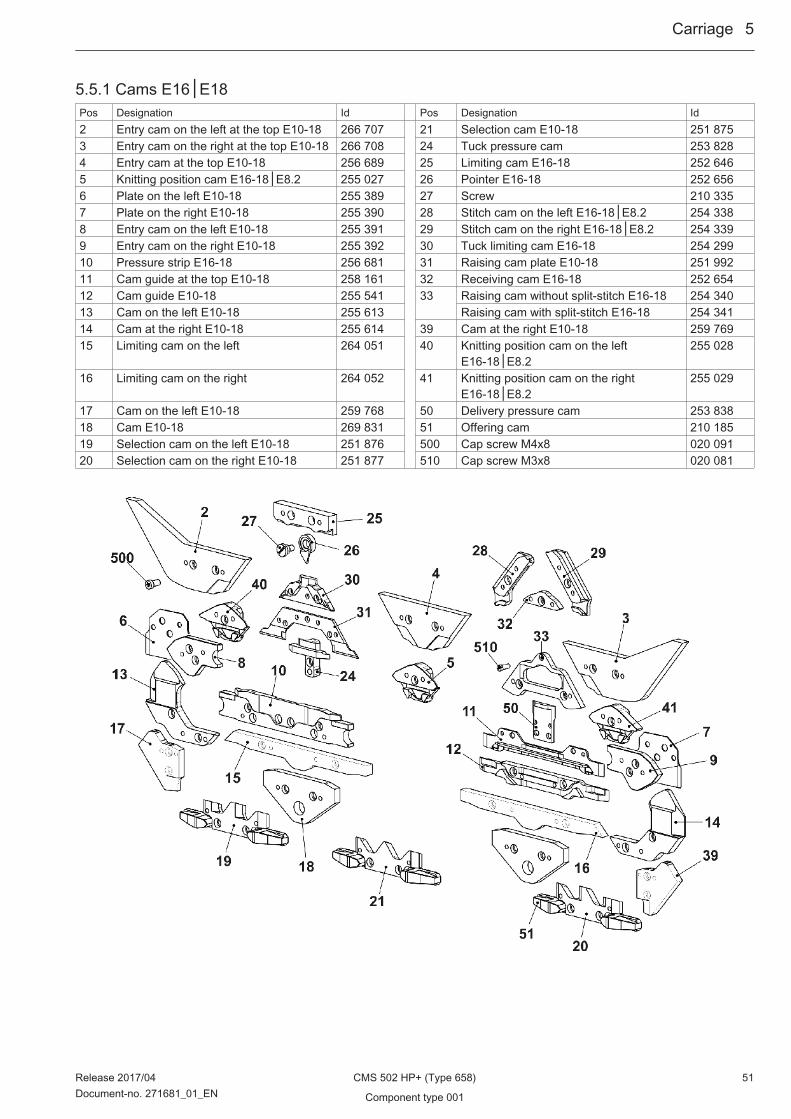
5.5.1 Cams E16│E18Pos Designation Id Pos Designation Id2 Entry cam on the left at the top E10-18 266 707 21 Selection cam E10-18 251 8753 Entry cam on the right at the top E10-18 266 708 24 Tuck pressure cam 253 8284 Entry cam at the top E10-18 256 689 25 Limiting cam E16-18 252 6465 Knitting position cam E16-18│E8.2 255 027 26 Pointer E16-18 252 6566 Plate on the left E10-18 255 389 27 Screw 210 3357 Plate on the right E10-18 255 390 28 Stitch cam on the left E16-18│E8.2 254 3388 Entry cam on the left E10-18 255 391 29 Stitch cam on the right E16-18│E8.2 254 3399 Entry cam on the right E10-18 255 392 30 Tuck limiting cam E16-18 254 29910 Pressure strip E16-18 256 681 31 Raising cam plate E10-18 251 99211 Cam guide at the top E10-18 258 161 32 Receiving cam E16-18 252 65412 Cam guide E10-18 255 541 33 Raising cam without split-stitch E16-18 254 34013 Cam on the left E10-18 255 613 Raising cam with split-stitch E16-18 254 34114 Cam at the right E10-18 255 614 39 Cam at the right E10-18 259 76915 Limiting cam on the left 264 051 40 Knitting position cam on the left
E16-18│E8.2255 028
16 Limiting cam on the right 264 052 41 Knitting position cam on the rightE16-18│E8.2
255 029
17 Cam on the left E10-18 259 768 50 Delivery pressure cam 253 83818 Cam E10-18 269 831 51 Offering cam 210 18519 Selection cam on the left E10-18 251 876 500 Cap screw M4x8 020 09120 Selection cam on the right E10-18 251 877 510 Cap screw M3x8 020 081
Carriage ...5
Release 2017/04 CMS 502 HP+ (Type 658) 51Document-no. 271681_01_EN Component type 001

5.6 Cam box E12m.10Pos Designation Id. no. Pos Designation Id. no.Σ Cam box complete E12m.10 269 850 1 Cam plate E10-18 269 843 37 d Circlip 023 56522 Stay bolt 254 839 e Disk 259 64723 Guide of pressure cam complete 253 480 f Washer 022 89334 Loop sinking cam on the left complete
E12-14254 248 38 Slider pressure cam complete 251 834
35 Loop sinking cam on the right completeE12-14
254 249 43 Holding piece 251 828
36 Rod guide on the left complete 252 662 503 Cap screw M3x6 022 58937 Rod guide on the right complete 252 663 505 Shim 0,5x12x75 236 654
a Rod guide part 258 148 509 Pan head screw M3x4 023 142b Spring rod 252 661 511 Shim 0,03x8x28 023 452c Compression spring 257 082 512 Shim 0,05x8x28 023 020
5...Carriage
52 CMS 502 HP+ (Type 658) Release 2017/04
Component type 001 Document-no. 271681_01_EN

5.6.1 Cams E12m.10Pos Designation Id Pos Designation Id2 Entry cam on the left at the top E10-18 266 707 21 Selection cam E10-18 251 8753 Entry cam on the right at the top E10-18 266 708 24 Tuck pressure cam 253 8284 Entry cam at the top E10-18 256 689 25 Limiting cam E10│E7.2 251 9935 Knitting position cam E10-14│E6.2│E7.2 255 021 26 Pointer E10 251 9946 Plate on the left E10-18 255 389 27 Screw 210 3357 Plate on the right E10-18 255 390 28 Stitch cam on the left E10-14│E7.2 254 3318 Entry cam on the left E10-18 255 391 29 Stitch cam on the right E10-14│E7.2 254 3329 Entry cam on the right E10-18 255 392 30 Tuck limiting cam E10│E7.2 254 29510 Pressure strip E10-14 255 540 31 Raising cam plate E10-18 251 99211 Cam guide at the top E10-18 258 161 32 Receiving cam E10-12 251 99712 Cam guide E10-18 255 541 33 Raising cam without split-stitch E10-12 254 33413 Cam E10-18 255 613 Raising cam with split-stitch E10-12 254 33514 Cam at the right E10-18 255 614 39 Cam at the right E10-18 259 76915 Limiting cam on the left 264 051 40 Knitting position cam on the left
E10-14│E6.2│E7.2255 022
16 Limiting cam on the right 264 052 41 Knitting position cam on the rightE10-14│E6.2│E7.2
255 023
17 Cam on the left E10-18 259 768 50 Delivery pressure cam 253 83818 Cam E10-18 269 831 51 Offering cam 210 18519 Selection cam on the left E10-18 251 876 500 Cap screw M4x8 020 09120 Selection cam on the right E10-18 251 877 510 Cap screw M3x8 020 081
Carriage ...5
Release 2017/04 CMS 502 HP+ (Type 658) 53Document-no. 271681_01_EN Component type 001
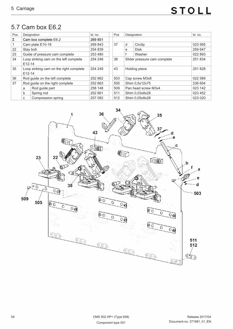
5.7 Cam box E6.2Pos Designation Id. no. Pos Designation Id. no.Σ Cam box complete E6.2 269 851 1 Cam plate E10-18 269 843 37 d Circlip 023 56522 Stay bolt 254 839 e Disk 259 64723 Guide of pressure cam complete 253 480 f Washer 022 89334 Loop sinking cam on the left complete
E12-14254 248 38 Slider pressure cam complete 251 834
35 Loop sinking cam on the right completeE12-14
254 249 43 Holding piece 251 828
36 Rod guide on the left complete 252 662 503 Cap screw M3x6 022 58937 Rod guide on the right complete 252 663 505 Shim 0,5x12x75 236 654
a Rod guide part 258 148 509 Pan head screw M3x4 023 142b Spring rod 252 661 511 Shim 0,03x8x28 023 452c Compression spring 257 082 512 Shim 0,05x8x28 023 020
5...Carriage
54 CMS 502 HP+ (Type 658) Release 2017/04
Component type 001 Document-no. 271681_01_EN
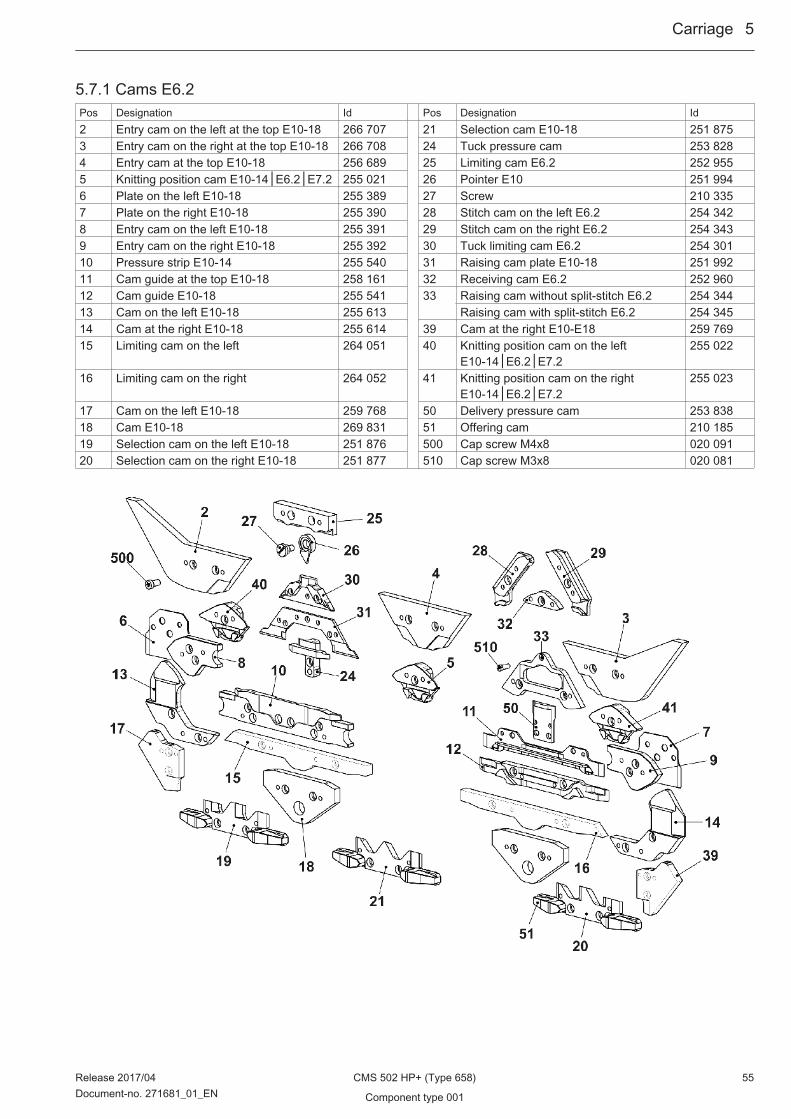
5.7.1 Cams E6.2Pos Designation Id Pos Designation Id2 Entry cam on the left at the top E10-18 266 707 21 Selection cam E10-18 251 8753 Entry cam on the right at the top E10-18 266 708 24 Tuck pressure cam 253 8284 Entry cam at the top E10-18 256 689 25 Limiting cam E6.2 252 9555 Knitting position cam E10-14│E6.2│E7.2 255 021 26 Pointer E10 251 9946 Plate on the left E10-18 255 389 27 Screw 210 3357 Plate on the right E10-18 255 390 28 Stitch cam on the left E6.2 254 3428 Entry cam on the left E10-18 255 391 29 Stitch cam on the right E6.2 254 3439 Entry cam on the right E10-18 255 392 30 Tuck limiting cam E6.2 254 30110 Pressure strip E10-14 255 540 31 Raising cam plate E10-18 251 99211 Cam guide at the top E10-18 258 161 32 Receiving cam E6.2 252 96012 Cam guide E10-18 255 541 33 Raising cam without split-stitch E6.2 254 34413 Cam on the left E10-18 255 613 Raising cam with split-stitch E6.2 254 34514 Cam at the right E10-18 255 614 39 Cam at the right E10-E18 259 76915 Limiting cam on the left 264 051 40 Knitting position cam on the left
E10-14│E6.2│E7.2255 022
16 Limiting cam on the right 264 052 41 Knitting position cam on the rightE10-14│E6.2│E7.2
255 023
17 Cam on the left E10-18 259 768 50 Delivery pressure cam 253 83818 Cam E10-18 269 831 51 Offering cam 210 18519 Selection cam on the left E10-18 251 876 500 Cap screw M4x8 020 09120 Selection cam on the right E10-18 251 877 510 Cap screw M3x8 020 081
Carriage ...5
Release 2017/04 CMS 502 HP+ (Type 658) 55Document-no. 271681_01_EN Component type 001

5.8 Cam box E7.2Pos Designation Id. no. Pos Designation Id. no.Σ Cam box complete E7.2 269 852 1 Cam plate E10-18 269 843 37 d Circlip 023 56522 Stay bolt 254 839 e Disk 259 64723 Guide of pressure cam complete 253 480 f Washer 022 89334 Loop sinking cam on the left complete
E12-14254 248 38 Slider pressure cam complete 251 834
35 Loop sinking cam on the right completeE12-14
254 249 43 Holding piece 251 828
36 Rod guide on the left complete 252 662 503 Cap screw M3x6 022 58937 Rod guide on the right complete 252 663 505 Shim 0,5x12x75 236 654
a Rod guide part 258 148 509 Pan head screw M3x4 023 142b Spring rod 252 661 511 Shim 0,03x8x28 023 452c Compression spring 257 082 512 Shim 0,05x8x28 023 020
5...Carriage
56 CMS 502 HP+ (Type 658) Release 2017/04
Component type 001 Document-no. 271681_01_EN

5.8.1 Cams E7.2Pos Designation Id Pos Designation Id2 Entry cam on the left at the top E10-18 266 707 21 Selection cam E10-18 251 8753 Entry cam on the right at the top E10-18 266 708 24 Tuck pressure cam 253 8284 Entry cam at the top E10-18 256 689 25 Limiting cam E10│E7.2 251 9935 Knitting position cam E10-14│E6.2│E7.2 255 021 26 Pointer E10 251 9946 Plate on the left E10-18 255 389 27 Screw 210 3357 Plate on the right E10-18 255 390 28 Stitch cam on the left E10-14│E7.2 254 3318 Entry cam on the left E10-18 255 391 29 Stitch cam on the right E10-14│E7.2 254 3329 Entry cam on the right E10-18 255 392 30 Tuck limiting cam E10│E7.2 254 29510 Pressure strip E10-14 255 540 31 Raising cam plate E10-18 251 99211 Cam guide E10-18 258 161 32 Receiving cam E10-12 251 99712 Cam guide E10-18 255 541 33 Raising cam without split-stitch E10-12 254 33413 Cam on the left E10-18 255 613 Raising cam with split-stitch E10-12 254 33514 Cam at the right E10-18 255 614 39 Cam at the right E10-18 259 76915 Limiting cam on the left 264 051 40 Knitting position cam on the left
E10-14│E6.2│E7.2255 022
16 Limiting cam on the right 264 052 41 Knitting position cam on the rightE10-14│E6.2│E7.2
255 023
17 Cam on the left E10-18 259 768 50 Delivery pressure cam 253 83818 Cam E10-18 269 831 51 Offering cam 210 18519 Selection cam on the left E10-18 251 876 500 Cap screw M4x8 020 09120 Selection cam on the right E10-18 251 877 510 Cap screw M3x8 020 081
Carriage ...5
Release 2017/04 CMS 502 HP+ (Type 658) 57Document-no. 271681_01_EN Component type 001

5.9 Cam box E8.2Pos Designation Id. no. Pos Designation Id. no.Σ Cam box complete E8.2 269 853 1 Cam plate E10-18 269 843 37 d Circlip 023 56522 Stay bolt 254 839 e Disk 259 64723 Guide of pressure cam complete 253 480 f Washer 022 89334 Loop sinking cam on the left complete
E16-18251 965 38 Slider pressure cam complete 251 834
35 Loop sinking cam on the right completeE16-18
251 966 43 Holding piece 251 828
36 Rod guide on the left complete 252 662 503 Cap screw M3x6 022 58937 Rod guide on the right complete 252 663 505 Shim 0,5x12x75 236 654
a Rod guide part 258 148 509 Pan head screw M3x4 023 142b Spring rod 252 661 511 Shim 0,03x8x28 023 452c Compression spring 257 082 512 Shim 0,05x8x28 023 020
5...Carriage
58 CMS 502 HP+ (Type 658) Release 2017/04
Component type 001 Document-no. 271681_01_EN

5.9.1 Cams E8.2Pos Designation Id Pos Designation Id2 Entry cam on the left at the top E10-18 266 707 21 Selection cam E10-18 251 8753 Entry cam on the right at the top E10-18 266 708 24 Tuck pressure cam 253 8284 Entry cam at the top E10-18 256 689 25 Limiting cam E8.2 260 9015 Knitting position cam E16-18│E8.2 255 027 26 Pointer E16-18 252 6566 Plate on the left E10-18 255 389 27 Screw 210 3357 Plate on the right E10-18 255 390 28 Stitch cam on the left E16-18│E8.2 254 3388 Entry cam on the left E10-18 255 391 29 Stitch cam on the right E16-18│E8.2 254 3399 Entry cam on the right E10-18 255 392 30 Tuck limiting cam E8.2 260 90210 Pressure strip E16-18 256 681 31 Raising cam plate E10-18 251 99211 Cam guide at the top E10-18 258 161 32 Receiving cam E8.2 260 90312 Cam guide E10-18 255 541 33 Raising cam without split-stitch E16-18 254 34013 Cam on the left E10-18 255 613 Raising cam with split-stitch E16-18 254 34114 Cam at the right E10-18 255 614 39 Cam at the right E10-18 259 76915 Limiting cam on the left 264 051 40 Knitting position cam on the left
E16-18│E8.2255 028
16 Limiting cam on the right 264 052 41 Knitting position cam on the rightE16-18│E8.2
255 029
17 Cam on the left E10-18 259 768 50 Delivery pressure cam 253 83818 Cam E10-18 269 831 51 Offering cam 210 18519 Selection cam on the left E10-18 251 876 500 Cap screw M4x8 020 09120 Selection cam on the right E10-18 251 877 510 Cap screw M3x8 020 081
Carriage ...5
Release 2017/04 CMS 502 HP+ (Type 658) 59Document-no. 271681_01_EN Component type 001

5.10 Carriage assemblyPos Designation Id Pos Designation IdΣ Carriage assembly 2 cam boxes complete 5 in‐
ches 502258 453 9 Bush 209 275
1 Carriage frame 2 cam boxes 5 inches 258 433 10 Bush 209 2742 Carriage part E10-18 265 496 11 Eccentric 222 9834 Shim 225 312 13 Locating bolt linking spot 244 1795 Shoulder screw 211 750 500 Cap screw M8x30 020 1438 Bush 207 546 520 Circlip6 021 022
5...Carriage
60 CMS 502 HP+ (Type 658) Release 2017/04
Component type 001 Document-no. 271681_01_EN
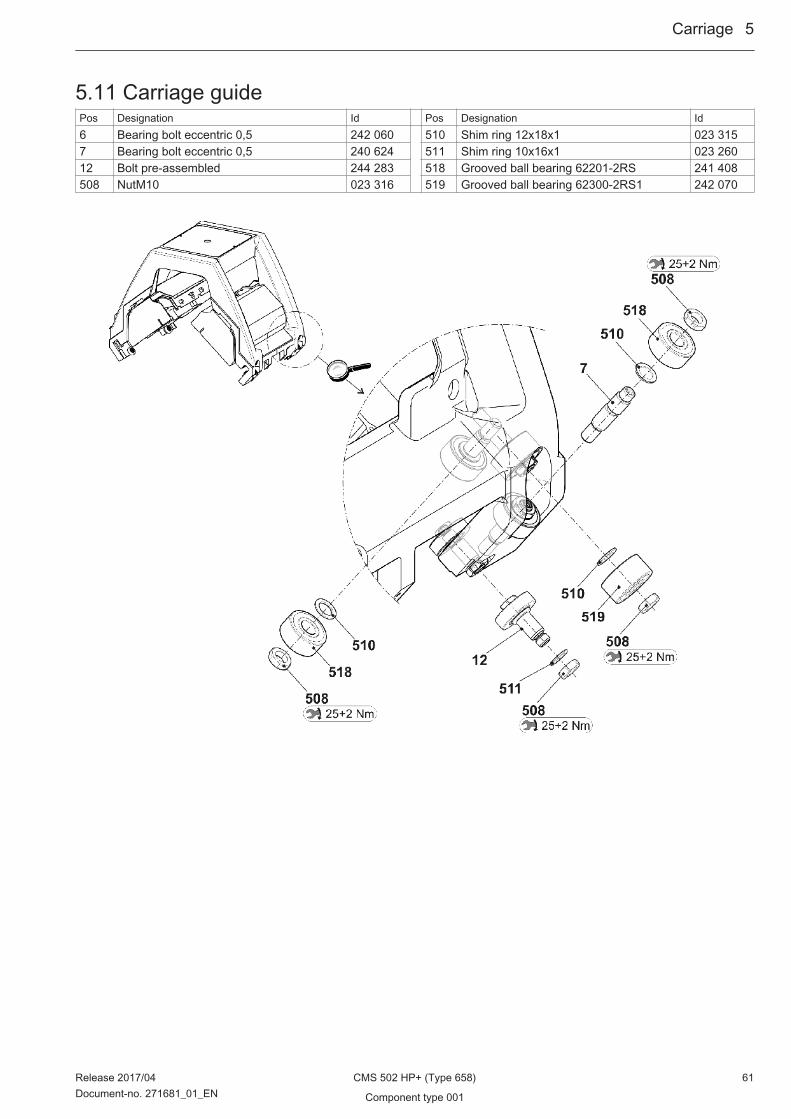
5.11 Carriage guidePos Designation Id Pos Designation Id6 Bearing bolt eccentric 0,5 242 060 510 Shim ring 12x18x1 023 3157 Bearing bolt eccentric 0,5 240 624 511 Shim ring 10x16x1 023 26012 Bolt pre-assembled 244 283 518 Grooved ball bearing 62201-2RS 241 408508 NutM10 023 316 519 Grooved ball bearing 62300-2RS1 242 070
Carriage ...5
Release 2017/04 CMS 502 HP+ (Type 658) 61Document-no. 271681_01_EN Component type 001

5.12 Carriage coverPos Designation ID Pos Designation ID1 Carriage cover at the top 2 cam boxes com‐
plete257 102 10 Locating bolt 242 382
1a Carriage cover at the top 2 cam boxes 253 317 500 Hexagon nut M6 257 0882 Carriage cover at the rear complete 2 cam
boxes257 175 501 Washer 6.1x9x0,5 023 554
2a Carriage cover at the rear 2 cam boxes 253 319 502 Serrated lock washer 6,4 022 3853 Carriage cover at the front 2 cam boxes com‐
plete257 174 503 O-ring 3x2 242 420
3a Carriage cover front 2 cam boxes 253 318 504 Compression spring 0,48x7,02x17,29 023 654
5...Carriage
62 CMS 502 HP+ (Type 658) Release 2017/04
Component type 001 Document-no. 271681_01_EN

5.13 Yarn Carrier DrivePos Designation Id Pos Designation IdΣ YC driving complete 268 845 1 Yarn carrier plunger complete 268 844 500 Cap screw M4x14-I-Torx 242 2792 Holding angle for jack 269 961 501 Cap screw M3x12-12.9 022 6483 Card yarn carrier final stages OKC 300 960 900 Cap screw M6x14 022 6584 Holding angle for YC driving 269 962 901 Shoulder screw 231 899
Carriage ...5
Release 2017/04 CMS 502 HP+ (Type 658) 63Document-no. 271681_01_EN Component type 001
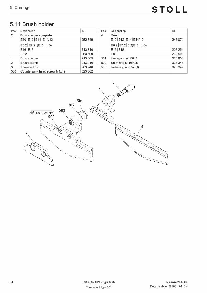
5.14 Brush holderPos Designation ID Pos Designation IDΣ Brush holder complete 4 Brush
E10│E12│E14│E14/12
E6.2│E7.2│(E12m.10)
252 749 E10│E12│E14│E14/12
E6.2│E7.2│6.2(E12m.10)
243 074
E16│E18 213 710 E16│E18 203 254E8.2 263 500 E8.2 260 502
1 Brush holder 213 009 501 Hexagon nut M8x4 020 8562 Brush clamp 213 010 502 Shim ring 5x10x0,5 023 3483 Threaded rod 209 740 503 Retaining ring 5x0,6 023 347500 Countersunk head screw M4x12 023 062
5...Carriage
64 CMS 502 HP+ (Type 658) Release 2017/04
Component type 001 Document-no. 271681_01_EN

5.15 Needle detectorPos Designation ID Pos Designation IDΣ Needle detector pre-assembled E10-18 256 475 503 Compression spring 4,3x0,45x10 021 3981 Cable of needle detector complete 261 856 504 Compression spring 0,32x4,00x13,10 256 9522 Retainer 256 476 505 Circlip2,3 021 0183 Switch rocker 256 477 506 Circlip1,9 023 5654 Set-out plate 256 094 12* Sensor pre-assembled E10-14 256 4545 Bolts 256 492 a* Sensor E10-14 255 7586 Stop bolt 256 493 b* Angle 255 757500 Pan-head screw M5x10 023 247 520* Pan-head screw M4x6 023 427501 Pan-head screw M2x8 258 310 16* Sensor pre-assembled E16-18 256 784502 Dowel pin4x10-A 023 753 a* Sensor E16-18 255 759
Carriage ...5
Release 2017/04 CMS 502 HP+ (Type 658) 65Document-no. 271681_01_EN Component type 001

5.16 Holding-down jack control and sliderPos Designation Id Pos Designation Id1 Holding-down jack control complete 20* Slider on the right complete
E10 256 306 E10 256 391E12│E14│E6.2(12m.10) │E7.2(14/12)│E6.2
256 307 E12│E14│E6.2(12m.10) │E7.2(14/12)│E6.2
256 392
E16│E18│E8.2 256 308 E16│E18│E8.2 256 393E7.2 256 309 E7.2 256 394E8.2 256 310 E8.2 256 395
511* Cap screw M5x16 023 141 30* Slider on the left complete E10 256 396
E12│E14│E6.2(12m.10) │E7.2(14/12)│E6.2
256 397
E16│E18│E8.2 256 398E7.2 256 399E8.2 256 400
a* Shim ring 5x10x0,5 023 348b* Retaining ring5x0,6 023 347
5...Carriage
66 CMS 502 HP+ (Type 658) Release 2017/04
Component type 001 Document-no. 271681_01_EN

5.17 Spare parts package carriage guide barPos Designation ID Pos Designation IDΣ Spare parts package carriage guide bar
ECO2253 883 501 Shim 0,05x22x42 243 291
1 Carriage guide rail 253 822 502 Shim 0,10x22x42 243 2922 Adjusting eccentric 241 219 503 Shim 0,20x22x42 243 293500 Shim 0,03x22x42 243 289 510* Cap screw M8x20 020 141
Carriage ...5
Release 2017/04 CMS 502 HP+ (Type 658) 67Document-no. 271681_01_EN Component type 001

5...Carriage
68 CMS 502 HP+ (Type 658) Release 2017/04
Component type 001 Document-no. 271681_01_EN

6 Main Take-down
Main Take-down ...6
Release 2017/04 CMS 502 HP+ (Type 658) 69Document-no. 271681_01_EN Component type 001

6.1 Main take-down E10│E12│E14│E6.2(12m.10)│E7.2(14/12)│E6.2│E7.2Pos Designation ID Pos Designation IDΣ Main Take-down E5-14 2 Main take-down on the right 268 5711 Main take-down on the left 268 572 3 Main take-down in the middle E5-14 267 683
6...Main Take-down
70 CMS 502 HP+ (Type 658) Release 2017/04
Component type 001 Document-no. 271681_01_EN

6.2 Main take-down E16│E18│E8.2Pos Designation ID Pos Designation IDΣ Main Take-down E16-18 2 Main take-down on the right 268 5711 Main take-down on the left 268 572 3 Main take-down in the middle E16-18 267 686
Main Take-down ...6
Release 2017/04 CMS 502 HP+ (Type 658) 71Document-no. 271681_01_EN Component type 001

6.3 Main take-down on the leftPos Designation Id Pos Designation IdΣ Main take-down on the left 268 572 2 Bearing race complete 244 459 21 Shoulder screw 257 0003 Shaft on the left at the rear 221 012 22 Distance bolt 256 0775 Bolts 208 538 23 Coupling piece 256 9997 Mounting plate on the left complete 267 031 25 Knurled screw 250 6089 Swivel-mounted bearing on the left 273 231 500 Screw 50x15 251 72811 Full floating axle on the left 251 984 504 Washer 18 023 29517 Spring bolt 221 143 505 Retaining ring 18x1,2 020 95519 Stop point 256 078 510 Hexagon nut M8-6 020 838
6...Main Take-down
72 CMS 502 HP+ (Type 658) Release 2017/04
Component type 001 Document-no. 271681_01_EN

6.4 Main take-down on the rightPos Designation Id Pos Designation IdΣ Main take-down on the right 268 571 1 Clutch set 251 677 10 Distance bolt 256 0772 Bearing race complete 244 459 11 Coupling piece 256 9993 Bolts 208 538 12 Knurled screw 250 6084 Mounting plate on the right complete 267 032 500 Screw 50x15 251 7285 Swivel-mounted bearing on the right 251 761 501 Washer 18 023 2956 Full floating axle on the right 251 985 502 Retaining ring 18x1,2 020 9557 Spring bolt 221 143 503 Hexagon nut M8-6 020 8388 Stop point 256 078 504 Microswitch Xgk2-s21 250 210 5109 Shoulder screw 257 000 505 Cap screw M3x16 022 583
Main Take-down ...6
Release 2017/04 CMS 502 HP+ (Type 658) 73Document-no. 271681_01_EN Component type 001

6.5 Mounting plate on the left and rightPos Designation ID Pos Designation IDΣ L Mounting plate on the left complete 267 031 Σ R Mounting plate on the right complete 267 0321 Mounting plate on the left 265 868 11 Mounting plate on the right 265 7572 Retaining plate on the left 231 539 12 Shoulder screw 240 0673 Shoulder screw 240 067 13 Retaining plate on the right 265 867500 Cap screw M5x8 244 278 513 Cap screw M5x8 244 278501 Washer 5-200 020 871 514 Washer 5-200 020 871
6...Main Take-down
74 CMS 502 HP+ (Type 658) Release 2017/04
Component type 001 Document-no. 271681_01_EN

6.6 Swivel-mounted bearingPos Designation Id Pos Designation IdΣ Swivel-mounted bearing 273 231 1 Swivel-mounted bearing 241 996 500 Screw M35x10 259 1022 Sheet metal support 251 749 504 Circlip 4 021 0203 Axle 251 758 505 Tension spring 21x3,0x192 240 217
Main Take-down ...6
Release 2017/04 CMS 502 HP+ (Type 658) 75Document-no. 271681_01_EN Component type 001
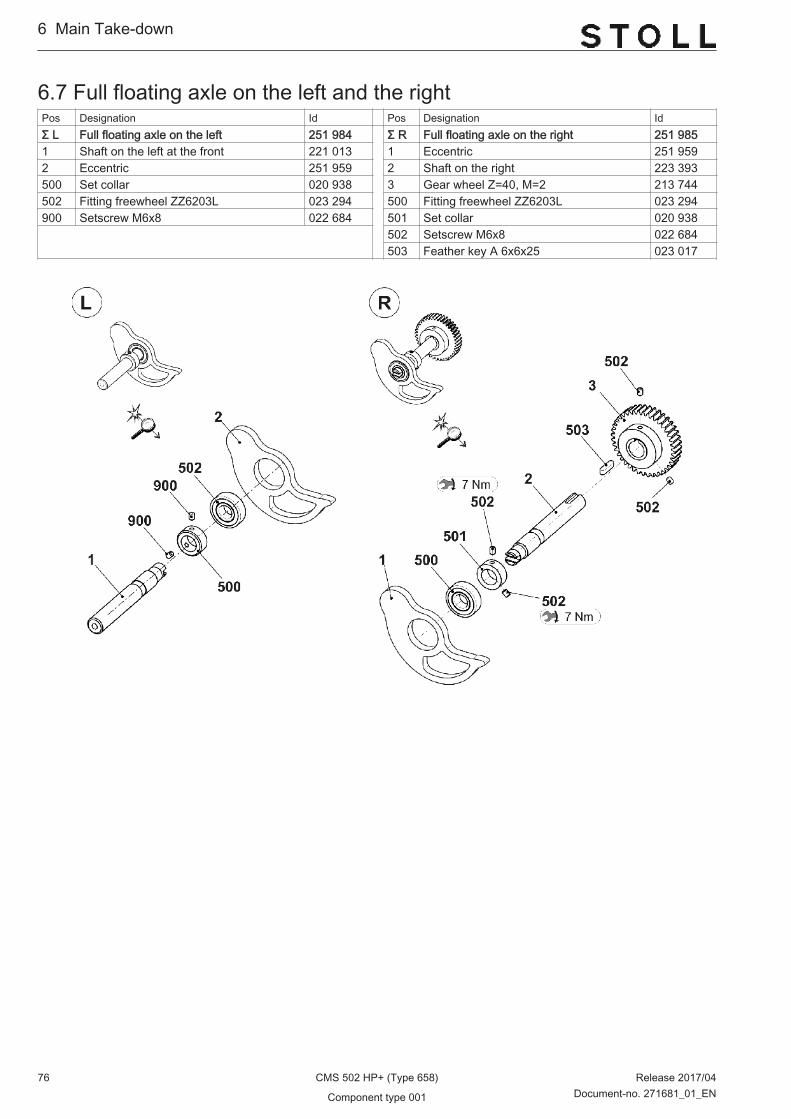
6.7 Full floating axle on the left and the rightPos Designation Id Pos Designation IdΣ L Full floating axle on the left 251 984 Σ R Full floating axle on the right 251 9851 Shaft on the left at the front 221 013 1 Eccentric 251 9592 Eccentric 251 959 2 Shaft on the right 223 393500 Set collar 020 938 3 Gear wheel Z=40, M=2 213 744502 Fitting freewheel ZZ6203L 023 294 500 Fitting freewheel ZZ6203L 023 294900 Setscrew M6x8 022 684 501 Set collar 020 938 502 Setscrew M6x8 022 684
503 Feather key A 6x6x25 023 017
6...Main Take-down
76 CMS 502 HP+ (Type 658) Release 2017/04
Component type 001 Document-no. 271681_01_EN

6.8 Main take-down in the middle E10│E12│E14│E6.2(12m.10)│E7.2(14/12)│E6.2│E7.2Pos Designation ID Pos Designation IDΣ Main take-down in the middle E5-14 267 683 21 Connecting rod 256 9984 Stripping angle 265 733 505 Washer 6 022 43112 Three phase servo motor of take-down 259 655 509 Cap screw M8x25 020 14213 Take-down roller at the rear complete
E5-14251 683 514 Cap screw M6x12 020 134
15 Take-down roller at the front completeE5-14
251 681 30* Sheet metal support on the left 251 766
17 Angle rail complete 251 550 31* Sheet metal support on the right 251 76520 Connection cable winding plate OKC5 267 012 530* Cap screw M6x12 020 134
Main Take-down ...6
Release 2017/04 CMS 502 HP+ (Type 658) 77Document-no. 271681_01_EN Component type 001

6.8.1 Rear take-down roller E10│E12│E14│E6.2(12m.10)│E7.2(14/12)│E6.2│E7.2Pos Designation Id Pos Designation IdΣ Take-down roller at the rear complete
E5-14251 683
1 Ring on the left 255 830 8 Spacer slide 222 0622 Stop ring on the left 204 369 9 Brush 225 8193 Shaft 251 682 12 Rod 251 7694 Stripper 241 612 13 Spacer slide 264 6695 Spacer slide 240 104 14 Roller 264 6246 Ring on the right 255 831 500 Dowel pin 6x32 020 6857 Roller 206 770 501 Setscrew M8x16 258 910
6...Main Take-down
78 CMS 502 HP+ (Type 658) Release 2017/04
Component type 001 Document-no. 271681_01_EN
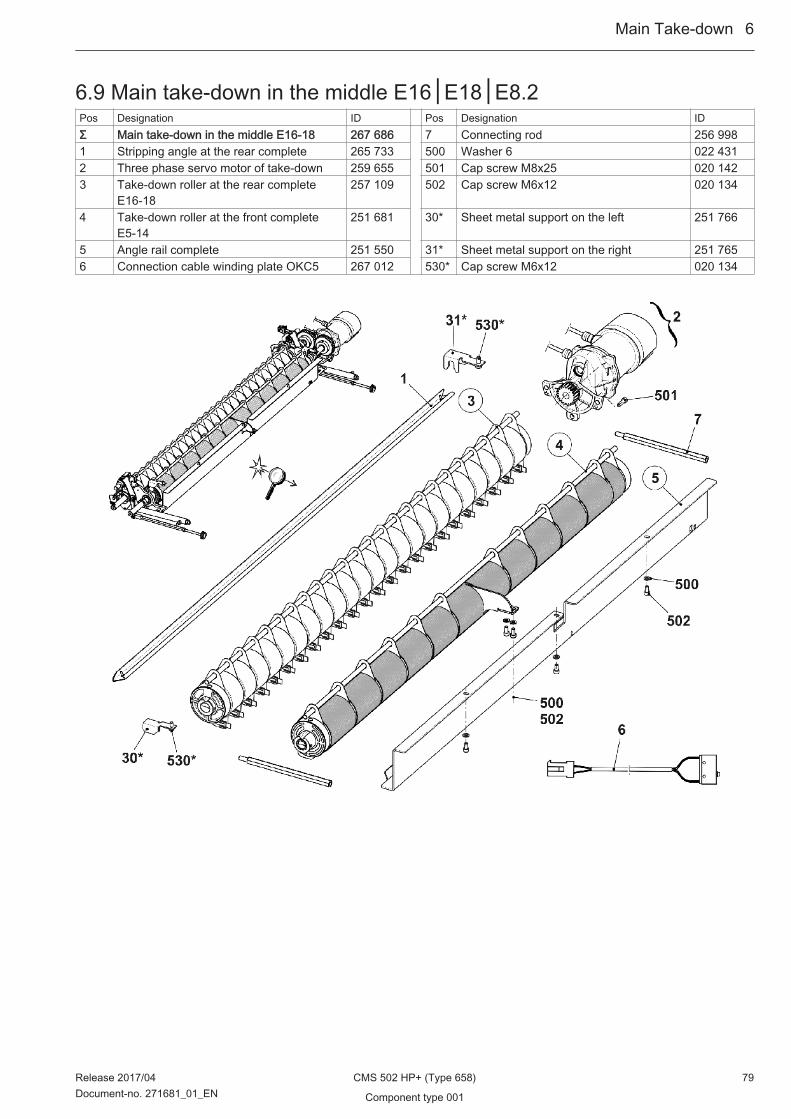
6.9 Main take-down in the middle E16│E18│E8.2Pos Designation ID Pos Designation IDΣ Main take-down in the middle E16-18 267 686 7 Connecting rod 256 9981 Stripping angle at the rear complete 265 733 500 Washer 6 022 4312 Three phase servo motor of take-down 259 655 501 Cap screw M8x25 020 1423 Take-down roller at the rear complete
E16-18257 109 502 Cap screw M6x12 020 134
4 Take-down roller at the front completeE5-14
251 681 30* Sheet metal support on the left 251 766
5 Angle rail complete 251 550 31* Sheet metal support on the right 251 7656 Connection cable winding plate OKC5 267 012 530* Cap screw M6x12 020 134
Main Take-down ...6
Release 2017/04 CMS 502 HP+ (Type 658) 79Document-no. 271681_01_EN Component type 001
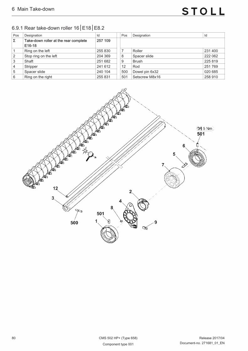
6.9.1 Rear take-down roller 16│E18│E8.2Pos Designation Id Pos Designation IdΣ Take-down roller at the rear complete
E16-18257 109
1 Ring on the left 255 830 7 Roller 231 4002 Stop ring on the left 204 369 8 Spacer slide 222 0623 Shaft 251 682 9 Brush 225 8194 Stripper 241 612 12 Rod 251 7695 Spacer slide 240 104 500 Dowel pin 6x32 020 6856 Ring on the right 255 831 501 Setscrew M8x16 258 910
6...Main Take-down
80 CMS 502 HP+ (Type 658) Release 2017/04
Component type 001 Document-no. 271681_01_EN

6.10 Front take-down rollerPos Designation Id Pos Designation IdΣ Take-down roller at the front complete 251 681 8 Spacer slide 222 0621 Ring on the left 255 830 10 Support 252 5062 Stop ring on the left 204 369 11 Stop ring on the left 222 9103 Shaft 251 680 12 Rod 251 7694 Stripper 241 612 13 Spacer slide 264 6695 Spacer slide 240 104 14 Roller 264 6246 Ring on the right 255 831 500 Dowel pin 6x32 020 6857 Roller 206 770 501 Setscrew M8x16 258 910
Main Take-down ...6
Release 2017/04 CMS 502 HP+ (Type 658) 81Document-no. 271681_01_EN Component type 001

6.11 Angle railPos Designation Id Pos Designation IdΣ Angle rail complete 251 550 501 Hexagon nut M5-8 023 5411 Switch complete (with cable) 221 265 502 Compression spring 0,8x9,2x27,5 023 5373 Angle rail 251 548 503 Cap screw M2x12 023 5224 Winding plate 251 549 504 Washer 2 022 908500 Washer 6 022 431 505 Shoulder screw M5x20x5 023 675
6...Main Take-down
82 CMS 502 HP+ (Type 658) Release 2017/04
Component type 001 Document-no. 271681_01_EN

7 Auxiliary Take-down
Auxiliary Take-down ...7
Release 2017/04 CMS 502 HP+ (Type 658) 83Document-no. 271681_01_EN Component type 001

7.1 Auxiliary Take-downPos Designation Id. no. Pos Designation Id. no.1 Auxiliary take-down pre-assembled 45" 267 911 5 Assembling element 209 5432 Take-down motor complete auxiliary take-
down265 820 500 Countersunk screw M6x10 023 016
3 Sheet metal guide 256 880 501* Cap screw M6x16 020 1354 Cover on the left 257 470 530* Pan head screw M6x12 235 935
7...Auxiliary Take-down
84 CMS 502 HP+ (Type 658) Release 2017/04
Component type 001 Document-no. 271681_01_EN

7.2 Auxiliary take-down pre-assembledPos Designation Id Pos Designation IdΣ Auxiliary take-down pre-assembled 268 627 10 Bolts 227 9141 Bearing on the right complete 268 631 11 Protective plate 264 9582 Bearing on the left complete 268 632 12 Support spring 264 9613 Toothed belt 10T5/260 208 832 500 Set collar 020 9344 Take-down roller 256 879 501 Stop disk 023 6465 Lever at the front on the left 264 036 502 Spring dowel sleeve 3x20 020 7766 Lever at the front on the right 264 035 503 Setscrew M5x6 023 3917 Lever at the rear on the left 264 034 504 Compression spring 1,0x8x59 264 9668 Lever at the rear on the right 264 033 505 Shim ring 10x16x1 023 2609 Timing belt pulley complete 226 708 506 Pan head screw M6x12 259 811
Auxiliary Take-down ...7
Release 2017/04 CMS 502 HP+ (Type 658) 85Document-no. 271681_01_EN Component type 001

7.2.1 Right bearing of the auxiliary take-downPos Designation Id Pos Designation IdΣ Bearing on the right complete 268 631 1 Bearing block on the right 258 913 13a Connecting rod 255 6962 Cover 257 466 531 Needle roller bearing HK1010 023 6643 Drive shaft complete 268 611 532 Slide bearing GFM-081014-06 023 3584 Drive shaft complete 268 610 500 Cap screw M3x16 022 5605 Gear wheel M=1,5, Z=20 213 880 501 Countersunk head screw M4x12 023 0626 Gear wheel M=1,5 , Z=20 210 504 502 Hexagon nut M6-6 020 8367 Gear wheel on the right complete 218 524 503 Shoulder screw M4x9x14 020 6028 Gear rack on the right 253 487 504 Setscrew M6x16-45 023 0929 Threaded spacer 229 683 505 Spiral pin 4x24 023 54410 Sleeve 227 257 506 Shim ring 10x16x1,5 023 26111 Collar bolt 210 551 507 Retaining ring 26x1,2 023 35912 Cable with switch auxiliary take-down
okc243 142 508 Tension spring 7,5x0,7x28 023 595
13 Connecting rod complete 226 710 509 Grooved ball bearing 6000-2Z 022 599
7...Auxiliary Take-down
86 CMS 502 HP+ (Type 658) Release 2017/04
Component type 001 Document-no. 271681_01_EN

7.2.2 Left bearing of the auxiliary take-downPos Designation Id Pos Designation IdΣ Bearing on the left 268 632 1 Bearing block on the left 258 914 8 Gear wheel on the left complete 218 5232 Cover 257 466 9 Gear rack on the left 253 4883 Drive shaft complete 268 612 500 Shoulder screw M4x9x14 020 6024 Bolts 268 609 501 Hexagon nut M6-6 020 8365 Collar bolt 210 551 502 Retaining ring 26x1,2 023 3596 Connecting rod complete 226 710 503 Shim ring 10x16x1,5 023 261
6a Connecting rod 255 696 504 Countersunk head screw M4x12 023 062530 Slide bearing GFM-081014-06 023 358 505 Grooved ball bearing 6000-2Z 022 599531 Needle roller bearing HK1010 023 664 506 Setscrew M6x16-45 023 092
7 Threaded spacer 229 683 507 Tension spring 7,5x0,7x28 023 595
Auxiliary Take-down ...7
Release 2017/04 CMS 502 HP+ (Type 658) 87Document-no. 271681_01_EN Component type 001

7.3 MotorPos Designation Id Pos Designation IdΣ Motor auxiliary take-down complete 265 820 1 Motor auxiliary take-down 266 528 500 Cap screw M3x6 022 5892 Motor bracket 218 040 501 Setscrew M6x10 023 5433 Drive sleeve 219 024 502 Cap screw M5x55 023 3214 Impulse disc 218 449 503 Compression spring 0,63x10,97x40 023 5005 Gear unit 4GN36K 220 353 504 Shim ring 6x12x1 023 4447 Light barrier Auxiliary take-down 217 462 508 Dowel pin5x28 241 6868 Shaft 219 025 520* Cap screw M6x12 020 134
7...Auxiliary Take-down
88 CMS 502 HP+ (Type 658) Release 2017/04
Component type 001 Document-no. 271681_01_EN

7.4 Yarn brake at clamping and cutting bedPos Designation Id Pos Designation IdΣ R Yarn brake on the right 256 715 1 Leaf spring 256 712 3 Cover on the right 256 7142 Test clamping plate 256 713 500 Cap screw M4x6 023 067
Auxiliary Take-down ...7
Release 2017/04 CMS 502 HP+ (Type 658) 89Document-no. 271681_01_EN Component type 001

7...Auxiliary Take-down
90 CMS 502 HP+ (Type 658) Release 2017/04
Component type 001 Document-no. 271681_01_EN

8 Comb Take-down
Comb Take-down ...8
Release 2017/04 CMS 502 HP+ (Type 658) 91Document-no. 271681_01_EN Component type 001

8.1 Comb Take-downPos Designation Id Pos Designation IdΣ Comb take-down 1 Comb take-down on the left 268 589 3 E12│E6.2│E6.2(12m.10) 267 6892 Comb take-down on the right 268 590 E14│E7.2│E7.2(14/12) 267 6813 Comb take-down in the middle E16│E8.2 267 691
E10 267 687 E18 267 694
8...Comb Take-down
92 CMS 502 HP+ (Type 658) Release 2017/04
Component type 001 Document-no. 271681_01_EN

8.2 Comb take-down on the leftPos Designation Id Pos Designation IdΣ Comb take-down on the left 268 589 28a Driving bolt 255 4271 Clamping piece 209 379 528 Hexagon nut M8-6 020 8382 Pressure plate 241 967 34 Swivel lever on the left 252 8593 Bolts 222 152 36 Clamping plate 227 1595 Toothed belt16T10/1300 240 065 500 Cap screw M6x16 020 1356 Eccentric pin 222 320 507 Cap screw M6x65 240 16211 Bolts 207 689 508 Cap screw M6x45 022 68914 Toothed lock washer at the bottom com‐
plete211 822 511 Hexagon nut M5-8 023 541
15 Toothed lock washer at the top complete 211 823 512 Hexagon nut M5-6 020 83517 Stay bolt 222 315 513 Hexagon nut M6-6 020 83618 Stay bolt 240 056 514 Hexagon nut M8-6 020 83819 Threaded rod M5 240 057 515 Hexagon nut M16-6 020 84520 Holding angle 242 487 517 Washer 16 020 87625 Reflector complete 256 826 524 Retaining ring17x1 023 29926 Guide bar C35 206 560 530 Tension spring Din2097 15x1,50x70,94 251 61427 Rubber buffer 206 561 531 Cap screw M6x12 020 13428 Comb guide on the left 255 425 540* Pan head screw M5x10 023 247
Comb Take-down ...8
Release 2017/04 CMS 502 HP+ (Type 658) 93Document-no. 271681_01_EN Component type 001

8.3 Comb take-down on the rightPos Designation Id Pos Designation IdΣ Comb take-down on the right 268 590 29b Angle 240 1121 Clamping piece 209 379 529 Hexagon nut M8-6 020 8382 Pressure plate 241 967 33 Swivel lever on the right 252 8583 Bolts 222 152 36 Clamping plate 227 1595 Toothed belt16T10/1300 240 065 500 Cap screw M6x16 020 1356 Eccentric pin 222 320 507 Cap screw M6x65 240 16212 Drive shaft comb complete 214 583 508 Cap screw M6x45 022 68914 Toothed lock washer at the bottom com‐
plete211 822 511 Hexagon nut M5-8 023 541
17 Stay bolt 222 315 512 Hexagon nut M5-6 020 83518 Stay bolt 240 056 513 Hexagon nut M6-6 020 83619 Threaded rod M5 240 057 514 Hexagon nut M8-6 020 83822 Proximity switch inductive at the top 231 516 515 Hexagon nut M16-6 020 84520 Holding angle 242487 517 Washer 16 020 87623 Proximity switch inductive at the bottom 231 520 530 Tension spring 15x1,50x70,94 251 61424 Light barrier complete 256 825 531 Cap screw M6x12 020 13426 Guide bar C35 206 560 532 Washer 6 020 87227 Rubber buffer 206 561 533* Shim0,2x12x27 023 73529 Comb guide on the right 255 424 534* Shim0,5x12x27 023 736
29a Driving bolt 255 427 540* Pan head screw M5x10 023 247
8...Comb Take-down
94 CMS 502 HP+ (Type 658) Release 2017/04
Component type 001 Document-no. 271681_01_EN
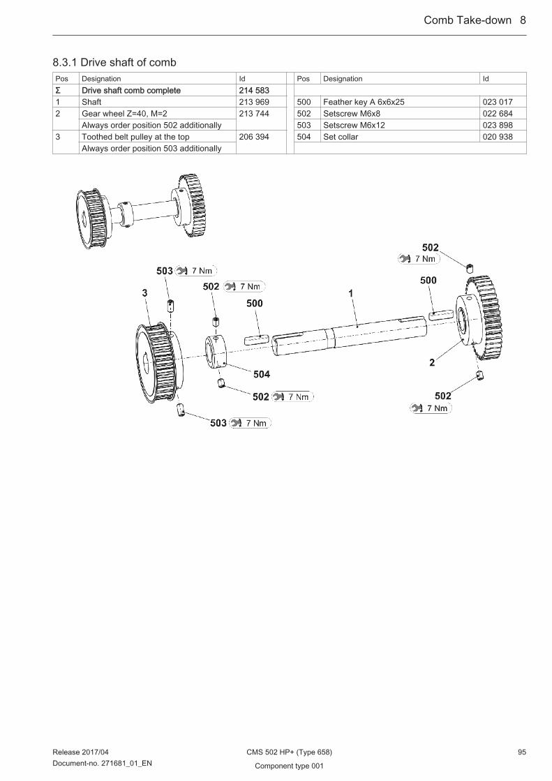
8.3.1 Drive shaft of combPos Designation Id Pos Designation IdΣ Drive shaft comb complete 214 583 1 Shaft 213 969 500 Feather key A 6x6x25 023 0172 Gear wheel Z=40, M=2 213 744 502 Setscrew M6x8 022 684
Always order position 502 additionally 503 Setscrew M6x12 023 8983 Toothed belt pulley at the top 206 394 504 Set collar 020 938
Always order position 503 additionally
Comb Take-down ...8
Release 2017/04 CMS 502 HP+ (Type 658) 95Document-no. 271681_01_EN Component type 001
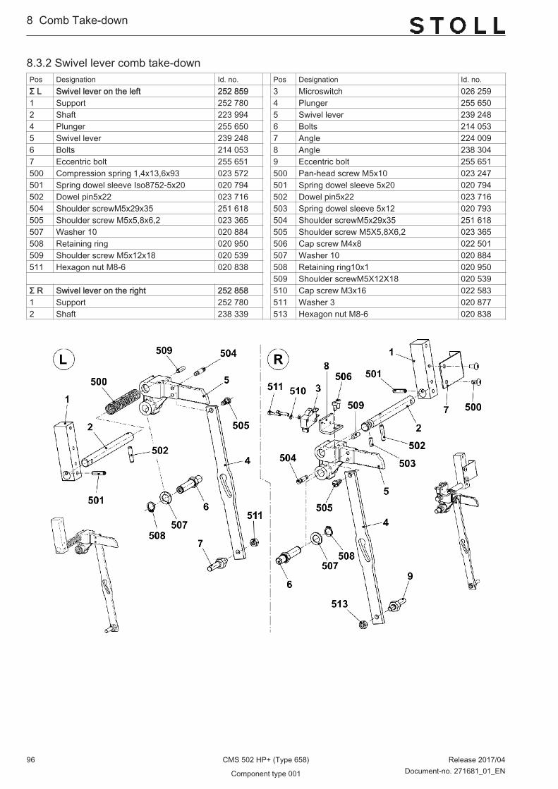
8.3.2 Swivel lever comb take-downPos Designation Id. no. Pos Designation Id. no.Σ L Swivel lever on the left 252 859 3 Microswitch 026 2591 Support 252 780 4 Plunger 255 6502 Shaft 223 994 5 Swivel lever 239 2484 Plunger 255 650 6 Bolts 214 0535 Swivel lever 239 248 7 Angle 224 0096 Bolts 214 053 8 Angle 238 3047 Eccentric bolt 255 651 9 Eccentric bolt 255 651500 Compression spring 1,4x13,6x93 023 572 500 Pan-head screw M5x10 023 247501 Spring dowel sleeve Iso8752-5x20 020 794 501 Spring dowel sleeve 5x20 020 794502 Dowel pin5x22 023 716 502 Dowel pin5x22 023 716504 Shoulder screwM5x29x35 251 618 503 Spring dowel sleeve 5x12 020 793505 Shoulder screw M5x5,8x6,2 023 365 504 Shoulder screwM5x29x35 251 618507 Washer 10 020 884 505 Shoulder screw M5X5,8X6,2 023 365508 Retaining ring 020 950 506 Cap screw M4x8 022 501509 Shoulder screw M5x12x18 020 539 507 Washer 10 020 884511 Hexagon nut M8-6 020 838 508 Retaining ring10x1 020 950 509 Shoulder screwM5X12X18 020 539Σ R Swivel lever on the right 252 858 510 Cap screw M3x16 022 5831 Support 252 780 511 Washer 3 020 8772 Shaft 238 339 513 Hexagon nut M8-6 020 838
8...Comb Take-down
96 CMS 502 HP+ (Type 658) Release 2017/04
Component type 001 Document-no. 271681_01_EN
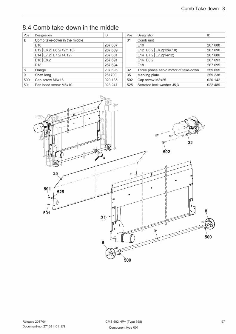
8.4 Comb take-down in the middlePos Designation ID Pos Designation IDΣ Comb take-down in the middle 31 Comb unit
E10 267 687 E10 267 688E12│E6.2│E6.2(12m.10) 267 689 E12│E6.2│E6.2(12m.10) 267 690E14│E7.2│E7.2(14/12) 267 681 E14│E7.2│E7.2(14/12) 267 680E16│E8.2 267 691 E16│E8.2 267 693E18 267 694 E18 267 695
8 Flange 207 695 32 Three phase servo motor of take-down 259 6559 Shaft long 251700 35 Marking plate 259 238500 Cap screw M6x16 020 135 502 Cap screw M8x25 020 142501 Pan head screw M5x10 023 247 525 Serrated lock washer J5,3 022 489
Comb Take-down ...8
Release 2017/04 CMS 502 HP+ (Type 658) 97Document-no. 271681_01_EN Component type 001

8.4.1 Comb unitPos Designation Id Pos Designation IdΣ Comb unit 5 Hook slider
E10 267 688 E10 261 989E12│E6.2│E6.2(12m.10) 267 690 E12│E16│E6.2│8.2│E6.2(12m.10) 251 709E14│E7.2 267 680 E14│E7.2 251 708E16│E8.2 271 508 E18 257 016E18 271 509 7 Collar bolt complete 211 036
1 Hook bed 8 Cross slider 251 701E10 265 410 9 Cover rail 251 702E12│E6.2│E6.2(12m.10) 265 411 10 Plunger 205 678E14│E7.2 265 412 11 Switching lever complete 265 827E16│E8.2 265 413 15 Stabilizer 251 697E18 265 414 500 Cap screw M4x12 022 664
2 Closer 502 Countersunk head screw M5x12 023 340E10│E12│E14│E6.2│E7.2│E6.2(12m.10) 230 106 504 Hexagon nut M4-8 023 046E16│E18│E8.2 268 833 505 Hexagon nut M5-04 020 854
3 Body 508 Washer 5 020 871E10│E12│E14│E6.2│E7.2│E6.2(12m.10) 230 094 510 Cap screw M4x35 023 550E16│E18│E8.2 268 832 511 Circlip 022 774
4 Cover rail 251 696
8...Comb Take-down
98 CMS 502 HP+ (Type 658) Release 2017/04
Component type 001 Document-no. 271681_01_EN
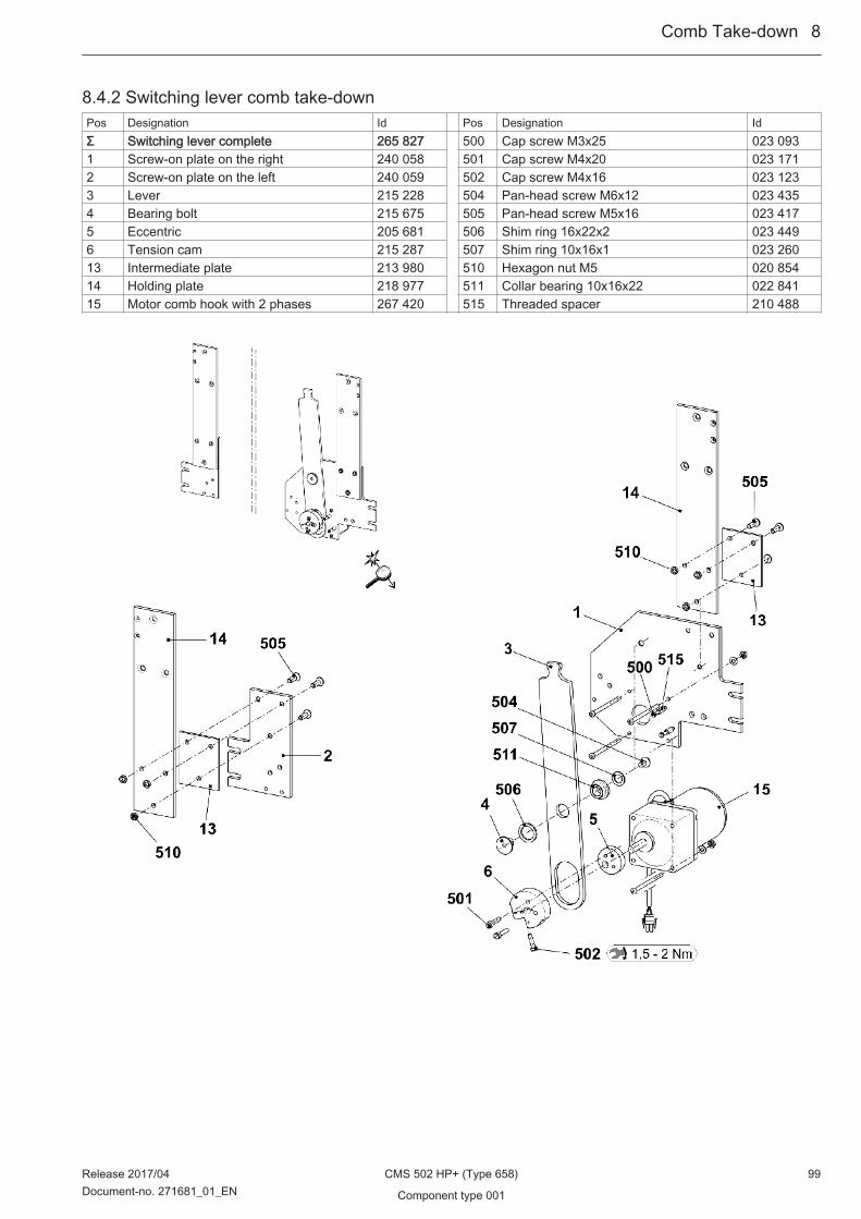
8.4.2 Switching lever comb take-downPos Designation Id Pos Designation IdΣ Switching lever complete 265 827 500 Cap screw M3x25 023 0931 Screw-on plate on the right 240 058 501 Cap screw M4x20 023 1712 Screw-on plate on the left 240 059 502 Cap screw M4x16 023 1233 Lever 215 228 504 Pan-head screw M6x12 023 4354 Bearing bolt 215 675 505 Pan-head screw M5x16 023 4175 Eccentric 205 681 506 Shim ring 16x22x2 023 4496 Tension cam 215 287 507 Shim ring 10x16x1 023 26013 Intermediate plate 213 980 510 Hexagon nut M5 020 85414 Holding plate 218 977 511 Collar bearing 10x16x22 022 84115 Motor comb hook with 2 phases 267 420 515 Threaded spacer 210 488
Comb Take-down ...8
Release 2017/04 CMS 502 HP+ (Type 658) 99Document-no. 271681_01_EN Component type 001

8...Comb Take-down
100 CMS 502 HP+ (Type 658) Release 2017/04
Component type 001 Document-no. 271681_01_EN

9 Belt Take-Down
Belt Take-Down ...9
Release 2017/04 CMS 502 HP+ (Type 658) 101Document-no. 271681_01_EN Component type 001

9.1 Belt Take-DownPos Designation Id Pos Designation IdΣ Belt take-down 1 Belt complete 266 958 13 Shim 266 8282 Drive unit complete 267 963 16 Thread clamp 267 5143 Gear unit complete 265 979 17 Cable between switch and winding plate
OKC5 BA267 952
4 Left support complete 265 982 500 Cap screw M6x16 020 1355 Winding guard complete 266 955 501 Washer 6 020 8729 Bearing strip at the bottom complete 266 827 502 Cap screw M6x25 023 33510 Yarn brake on the rightE12-18 265 657 503 Countersunk screw M6x14 266 777
Yarn brake on the rightE5-10 267 907 504 Feather key 6x6x20 265 78811 Cover on the left E12-18 267 261 505 Cap screw M6x20 023 180
Cover on the left E5-10 267 983 506 Cap screw M6x8 023 53212 Coupling 265 693 507 Cap screw M8x25 023 563
9...Belt Take-Down
102 CMS 502 HP+ (Type 658) Release 2017/04
Component type 001 Document-no. 271681_01_EN

9.2 BeltPos Designation Id Pos Designation IdΣ Belt complete 266 958 6 Casing cap at the right 266 3821 Drive shaft of belt take-down 266 954 7 Casing cap at the left 266 3832 Bolts 265 633 8 Support 265 6303 Support 266 952 500 Screw 50x20 263 5404 Shaft 266 953 501 Dowel pin 6x28 265 7845 Belt 266 960 502 Slide bearing 266 772
Belt Take-Down ...9
Release 2017/04 CMS 502 HP+ (Type 658) 103Document-no. 271681_01_EN Component type 001

9.3 Drive unitPos Designation Id Pos Designation IdΣ Drive unit complete 267 963 1 Motor complete 267 626 8 Toothed belt 560 265 7382 Plate at the top 266 818 500 Retaining ring20x1,2 020 9563 Motor support 266 819 501 Grooved ball bearing 6204-2RS 022 8484 Timing belt pulley 44-HTD8M 265 624 502 Grooved ball bearing 6004-2RS 236 0895 Shaft 265 634 503 Cap screw M8x25 023 5636 Flange 266 820 504 Setscrew M16x12 023 8987 Eccentric 266 612 505 Feather key 6x6x20 265 788
9...Belt Take-Down
104 CMS 502 HP+ (Type 658) Release 2017/04
Component type 001 Document-no. 271681_01_EN

9.4 Support on the leftPos Designation Id Pos Designation IdΣ Left support complete 265 982 540 Cap screw M2x12 023 5221 Support angle 266 417 550 Switch of Winding PlateBA 266 6132 Switch component complete 265 981 3 Support 266 418
10 Support on the left 266 821 4 Holding angle at the left 265 70420 Screw-on plate 266 419 5 Bearing strip at the top complete 266 82530 Switch plate 266 822 500 Grooved ball bearing 6000-2Z 022 59940 Operating shaft 266 823 501 Cap screw M6x40 020 14050 Tension bar 266 824 502 Countersunk screw M4x12 023 062510 Cap screw M4x8 022 501 503 Cap screw M5x8 023 319520 Tension spring 023 308 504 NutM6x8 265 785530 Compression spring 023 464 505 Cap screw M3x8 022 582
Belt Take-Down ...9
Release 2017/04 CMS 502 HP+ (Type 658) 105Document-no. 271681_01_EN Component type 001

9.5 Winding guardPos Designation Id Pos Designation IdΣ Winding guard complete 266 955 A Stripping angle at the rear complete 266 956 4 Shaft 265 697B Stripping angle in the front complete 266 957 500 Dowel pin2x10 266 7221 Stripping angle 266 949 501 Cap screw M5x8 023 3192 Stripping brush 266 950 502 Pan head screw M3x5 023 5303 Brush antistatic 266 951 503 Pan head screw M3x5 235 966
9...Belt Take-Down
106 CMS 502 HP+ (Type 658) Release 2017/04
Component type 001 Document-no. 271681_01_EN

9.6 Yarn brakePos Designation Id Pos Designation IdΣ R Yarn brake on the right 265 657 1 Cover on the right 265 656 3 Test clamping plate 256 7132 Leaf spring 256 712 500 Cap screw M4x6 023 067
Belt Take-Down ...9
Release 2017/04 CMS 502 HP+ (Type 658) 107Document-no. 271681_01_EN Component type 001

9...Belt Take-Down
108 CMS 502 HP+ (Type 658) Release 2017/04
Component type 001 Document-no. 271681_01_EN

10 Yarn delivery device
Yarn delivery device ...10
Release 2017/04 CMS 502 HP+ (Type 658) 109Document-no. 271681_01_EN Component type 001

10.1 Yarn guide device Pos Designation Id. no. Pos Designation Id. no.Σ Yarn guide device 14 FKE 45“ 269 181 8 Straps 267 2581 Straps 267 213 9 Slot nut 228 8512 Yarn control device (FKE) 267 212 10 Ground cable 270 2343 Cable FKE 502 269 410 500 Self-locking screw M6x12 023 4154 Support on the left 267 256 501 Screw M6x20 023 7215 Support on the right 267 257 502 Serrated nut M6-10 023 4146 Yarn guide bracket complete 241 581 503 Sheet metal screw 243 0757 Yarn guide bar 45“ 251 631 504 Pan-head screw M8x16 023 113
10...Yarn delivery device
110 CMS 502 HP+ (Type 658) Release 2017/04
Component type 001 Document-no. 271681_01_EN
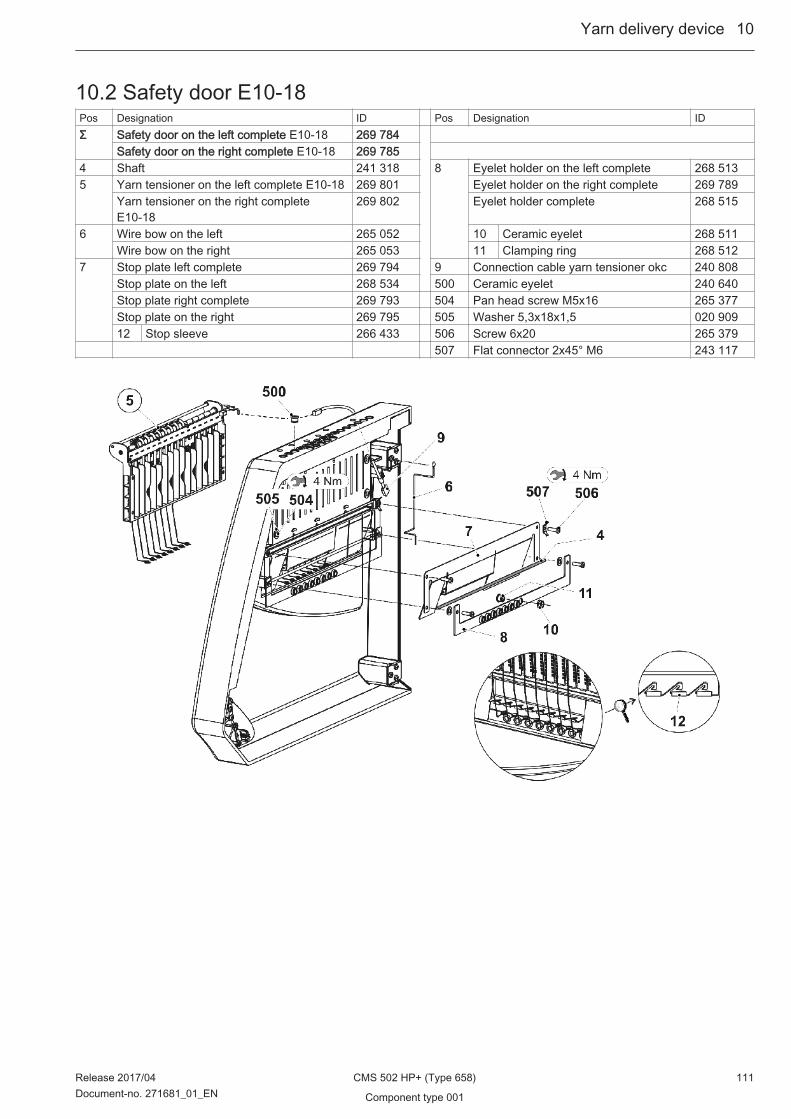
10.2 Safety door E10-18Pos Designation ID Pos Designation IDΣ Safety door on the left complete E10-18 269 784
Safety door on the right complete E10-18 269 785 4 Shaft 241 318 8 Eyelet holder on the left complete 268 5135 Yarn tensioner on the left complete E10-18 269 801 Eyelet holder on the right complete 269 789
Yarn tensioner on the right completeE10-18
269 802 Eyelet holder complete 268 515
6 Wire bow on the left 265 052 10 Ceramic eyelet 268 511Wire bow on the right 265 053 11 Clamping ring 268 512
7 Stop plate left complete 269 794 9 Connection cable yarn tensioner okc 240 808Stop plate on the left 268 534 500 Ceramic eyelet 240 640Stop plate right complete 269 793 504 Pan head screw M5x16 265 377Stop plate on the right 269 795 505 Washer 5,3x18x1,5 020 90912 Stop sleeve 266 433 506 Screw 6x20 265 379
507 Flat connector 2x45° M6 243 117
Yarn delivery device ...10
Release 2017/04 CMS 502 HP+ (Type 658) 111Document-no. 271681_01_EN Component type 001
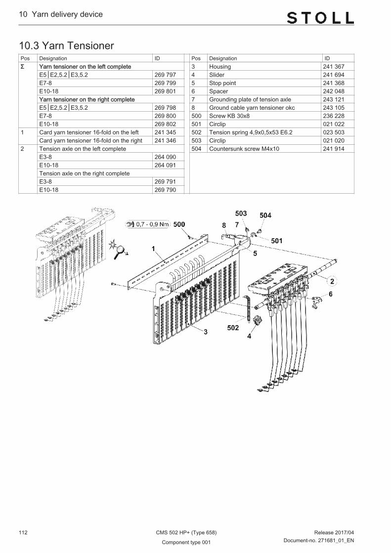
10.3 Yarn TensionerPos Designation ID Pos Designation IDΣ Yarn tensioner on the left complete 3 Housing 241 367
E5│E2,5.2│E3,5.2 269 797 4 Slider 241 694E7-8 269 799 5 Stop point 241 368E10-18 269 801 6 Spacer 242 048Yarn tensioner on the right complete 7 Grounding plate of tension axle 243 121E5│E2,5.2│E3,5.2 269 798 8 Ground cable yarn tensioner okc 243 105E7-8 269 800 500 Screw KB 30x8 236 228E10-18 269 802 501 Circlip 021 022
1 Card yarn tensioner 16-fold on the left 241 345 502 Tension spring 4,9x0,5x53 E6.2 023 503Card yarn tensioner 16-fold on the right 241 346 503 Circlip 021 020
2 Tension axle on the left complete 504 Countersunk screw M4x10 241 914E3-8 264 090 E10-18 264 091Tension axle on the right completeE3-8 269 791E10-18 269 790
10...Yarn delivery device
112 CMS 502 HP+ (Type 658) Release 2017/04
Component type 001 Document-no. 271681_01_EN

10.3.1 Tension axlePos Designation ID Pos Designation IDΣ Tension axle on the left complete E3-8 264 090 5 Thread clamp AKF 238 695
Tension axle on the right complete E3-8 269 791 51 Housing AKF 238 689Tension axle on the left complete E10-18 264 091 52 Cover AKF 237 926Tension axle on the right complete E10-18 269 790 53 Sheet metal at the bottom (hous‐
ing AKF)240 719
1 Axle 243 107 54 Lever AKF 238 6922 Tension arm pre-assembled E3-8 259 448 55 Pressure piece AKF 238 690
Tension arm pre-assembled E10-18 258 459 56 Slider AKF 238 6916 Wire bow 238 694 57 Wire bow 238 694500 Shim ring 8x14x0,5 023 501 58 Wire 237 940501 Circlip 021 022 551 Screw KB 35x12 237 681502 Grooved pin 2x6 243 172 552 Screw KB 40x8 236 227 553 Compression spring
0,30x4,50x18,50241 437
554 Grooved pin 2x6 243 172
Yarn delivery device ...10
Release 2017/04 CMS 502 HP+ (Type 658) 113Document-no. 271681_01_EN Component type 001

10.4 Bobbin boardPos Designation Id. no. Pos Designation Id. no.Σ Table complete 45’’ 272 469 14 Support of right feed wheel 264 4541 Table 269 558 15 Slot nut 228 8512 Support element 228 594 17 Lamp LED complete 268 7224 Connection cable of covers 264 128 503 Pan head screw M8x18 251 3316 Card safety door switch middle 270 127 504 Pan head screw M8x10 241 9307 Guide rail at the top 264 129 505 Pan head screw M8x16 023 1138 Cable of covers 272 185 506 Washer 5 020 9019 Positioning pin 204 819 509 Cap screw 3x4 022 80513 Connection cable of yarn control unit, sig‐
nal light269 509 520 Pan head screw M6x16 023 124
10...Yarn delivery device
114 CMS 502 HP+ (Type 658) Release 2017/04
Component type 001 Document-no. 271681_01_EN

10.5 Yarn guide complete E10-18Pos Designation Track Id. no. Pos Designation Id. no.Σ Yarn guide complete
E10│E12│E14│E6.2(12m.10)│E7.2(14/12)│E7.2│E8.2
253 832
E16│E18 256 932E10│E12│E14│E6.2(12m.10)│E7.2(14/12)│E7.2│E8.2 E10│E12│E14│E6.2(12m.10)│E7.2(14/12)│E7.2│E8.21 FF carriage complete E10-14 1+8 243 943 1a FF bow 1+8 complete E10-14 212 9942 FF carriage complete E10-14 2+7 243 942 2a FF bow 2+7 complete E10-14 212 9963 FF carriage complete E10-14 3+6 243 941 3a FF bow 3+6 complete E10-14 212 9954 FF carriage complete E10-14 4+5 243 940 4a FF bow 4+5 complete E10-14 212 997E16│E18 E16│E181 FF carriage complete E16-18 1+8 243 947 1a FF bow 1+8 complete E16-18 223 1992 FF carriage complete E16-18 2+7 243 946 2a FF bow 2+7 complete E16-18 223 2013 FF carriage complete E16-18 3+6 243 945 3a FF bow 3+6 complete E16-18 223 2004 FF carriage complete E16-18 4+5 243 944 4a FF bow 4+5 complete E16-18 223 202 10 FF carriage complete 243 062 13 Shim 213 03511 Yarn guide star complete 209 257 500 Hexagon screw M5x10 020 351
Yarn delivery device ...10
Release 2017/04 CMS 502 HP+ (Type 658) 115Document-no. 271681_01_EN Component type 001

10.6 Bar unitPos Designation Id. no. Pos Designation Id. no.Σ Bar unit 1 Yarn carrier rail 267 840 700 Yarn guide bracket complete 269 4092 FF support 268 418 710 Eyelet holder complete 268 4243 Limiter 268 410 720 Ceramic eyelet 268 511500 Cap screw M6x35 020 139 730 Clamping ring 268 512600 Cap screw M8x25 020 142 740 Cap screw M6x12 020 134
10...Yarn delivery device
116 CMS 502 HP+ (Type 658) Release 2017/04
Component type 001 Document-no. 271681_01_EN

10.7 Right friction feed wheelPos Designation ID Pos Designation IDΣ Friction feed wheel on the right 269 398 1 Three-phase AC motor complete 219 800 2 Friction roller complete 269 400
1a Micro Switches 008 664 3 Ribbed V-belt V3J 406 206 927
Yarn delivery device ...10
Release 2017/04 CMS 502 HP+ (Type 658) 117Document-no. 271681_01_EN Component type 001
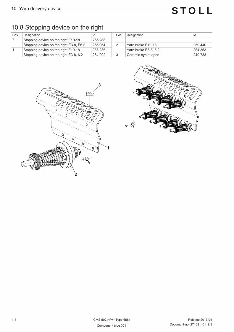
10.8 Stopping device on the rightPos Designation Id Pos Designation IdΣ Stopping device on the right E10-18 265 288
Stopping device on the right E3-8, E6.2 265 054 2 Yarn brake E10-18 259 4401 Stopping device on the right E10-18 265 286 Yarn brake E5-8, 6.2 264 353
Stopping device on the right E3-8, 6.2 264 992 3 Ceramic eyelet open 240 733
10...Yarn delivery device
118 CMS 502 HP+ (Type 658) Release 2017/04
Component type 001 Document-no. 271681_01_EN

11 Operation and control
Operation and control ...11
Release 2017/04 CMS 502 HP+ (Type 658) 119Document-no. 271681_01_EN Component type 001

11.1 Input unitPos Designation Id Pos Designation IdΣ Display touch 19 Display support on the right 264 19116 Display touch complete 268 259 510 Pan head screw M5x8 239 40816a Pencil touch 242 812 514 Pan head screw M6x108 023 18318 Display support on the left 264 192 520 Washer 6,1x12,2x1,2 023 598
11...Operation and control
120 CMS 502 HP+ (Type 658) Release 2017/04
Component type 001 Document-no. 271681_01_EN

11.2 Starting devicePos Designation Id Pos Designation IdΣ Starting device 268 576 13 Bearing on the right 264 8001 Engaging Rod 251 686 501 Cap screw M6x20 020 1362 Bearing on the left complete 250 071 502 Screw M6x25 023 5103 Guide rail at the bottom pre-assembled 268 575 503 Cap screw M6x16 020 1356* Cover plate on the right 251 691 504 Pan head screw M5x14 023 5887* Cover plate on the left 251 690 507 Cap screw M6x20-12.9 020 1368 Bearing on the right complete 265 444 508 Washer 6 020 8729 Cable switch safety doors 223 350 511 Cable holder 262 03711 Locating bolt 219 107 512 Cap screw M6x10 023 69012 Slot nut 225 099 513 Pan head screw M5x10 023 247
Operation and control ...11
Release 2017/04 CMS 502 HP+ (Type 658) 121Document-no. 271681_01_EN Component type 001

11.2.1 Bearing of the engaging rodPos Designation Id. no. Pos Designation Id. no.L Bearing on the left complete 250 071 502 Shim ring 4x8x1 023 3691 Bearing on the left 245 218 503 Card engaging 259 000
1a
Clip bearing MCM 12-04 023 639 504 Adhesive magnet direct current 026 233
2 Support of buffer 220 561 505 Hexagon nut M8-6 020 8382a
O-ring 14x4 023 237 506 Dowel pin 1,5x8 236 923
3 Shaft on the left 245 219 507 Spring dowel sleeve 6x20 023 7194 Anchor 253 776 508 Shoulder screw M4x24,8x7,7 240 2995 Switch flag 245 220 509 Shoulder screw 251 3166 Spring mandrel 251 340 510 Shim ring 12x18x1 023 3157 Disk 245 222 511 Retaining ring 12x1 020 9518 Shoulder screw 254 528 512 Compression spring 1,25x15x98,2 023 6099 Distance bolt 240 287 513 Compression spring 0,5x11x20,21 265 082500 Cap screw M4x6 023 067 1R Bearing on the right 264 800501 Cap screw M4x8 022 501 1Ra Clip bearing MCM 08-03 253 072
11...Operation and control
122 CMS 502 HP+ (Type 658) Release 2017/04
Component type 001 Document-no. 271681_01_EN

11.3 Shock stop motionPos Designation Id. no. Pos Designation Id. no.Σ Shock stop motion complete 255 435 2 Connecting cable piezo sensor 220 0631 Shock stop motion (Piezo) 220 011 3 End plug piezo sensor 220 053
Operation and control ...11
Release 2017/04 CMS 502 HP+ (Type 658) 123Document-no. 271681_01_EN Component type 001
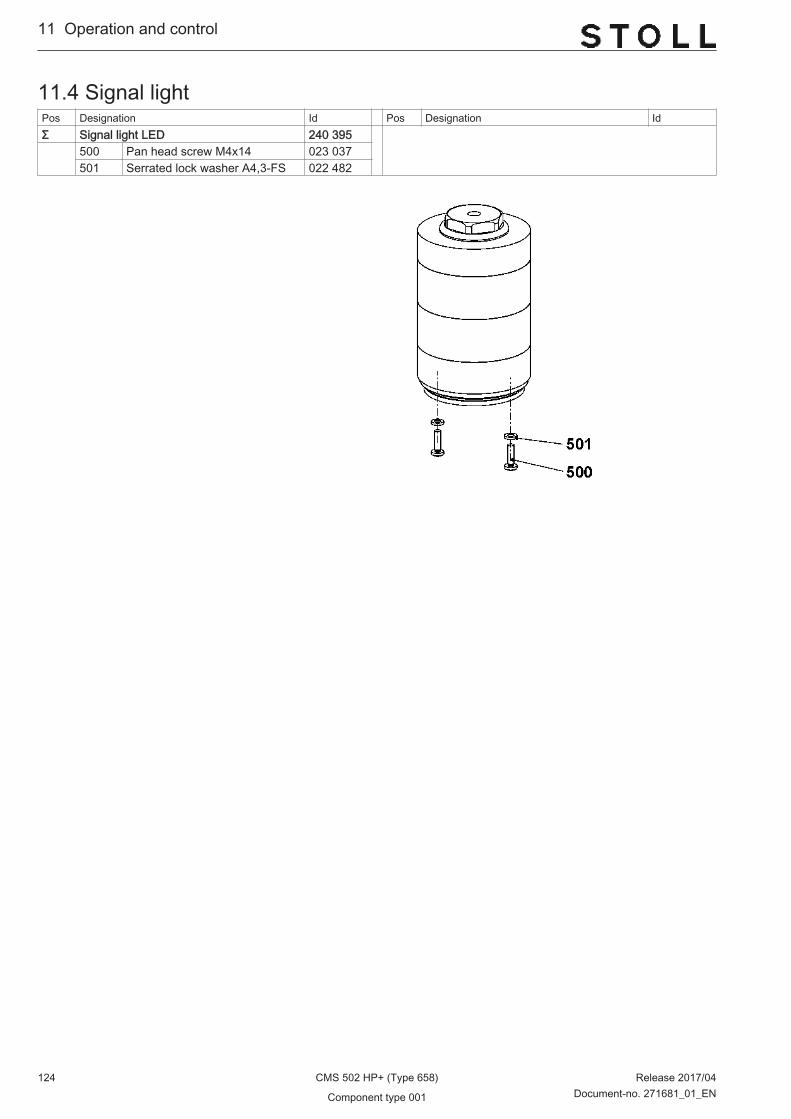
11.4 Signal lightPos Designation Id Pos Designation IdΣ Signal light LED 240 395 500 Pan head screw M4x14 023 037
501 Serrated lock washer A4,3-FS 022 482
11...Operation and control
124 CMS 502 HP+ (Type 658) Release 2017/04
Component type 001 Document-no. 271681_01_EN

11.5 Control of Collecting AreaPos Designation Id Pos Designation IdΣ Reflector complete 256 826 Σ Light barrier complete 256 8251 Mounting plate reflector 256 675 1 Holding angle light barrier 256 674500 Blind rivet A3x8-Al 023 158 500 Cap screw M3x10 022 991501 Reflector 20x20 mm 243 356 501 Light Barrier 243 355900* Cap screw M6x12 020 134 900* Cap screw M6x12 020 134 901* Washer 6 020 872
Operation and control ...11
Release 2017/04 CMS 502 HP+ (Type 658) 125Document-no. 271681_01_EN Component type 001
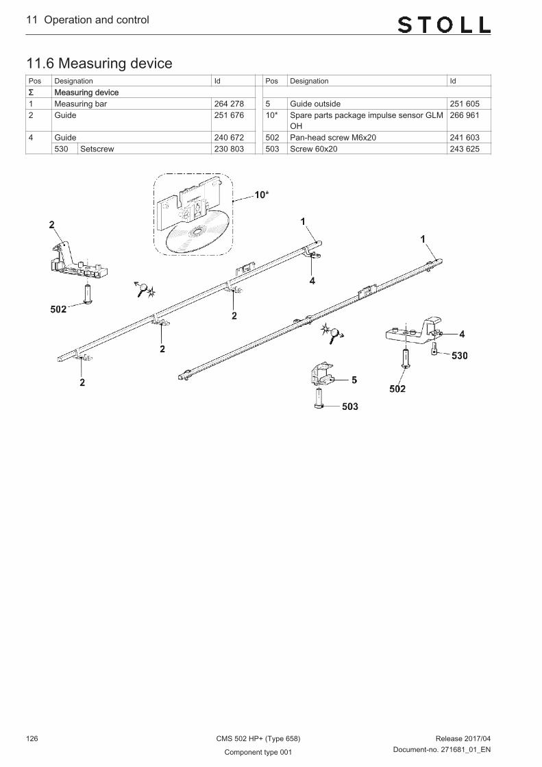
11.6 Measuring devicePos Designation Id Pos Designation IdΣ Measuring device 1 Measuring bar 264 278 5 Guide outside 251 6052 Guide 251 676 10* Spare parts package impulse sensor GLM
OH266 961
4 Guide 240 672 502 Pan-head screw M6x20 241 603530 Setscrew 230 803 503 Screw 60x20 243 625
11...Operation and control
126 CMS 502 HP+ (Type 658) Release 2017/04
Component type 001 Document-no. 271681_01_EN
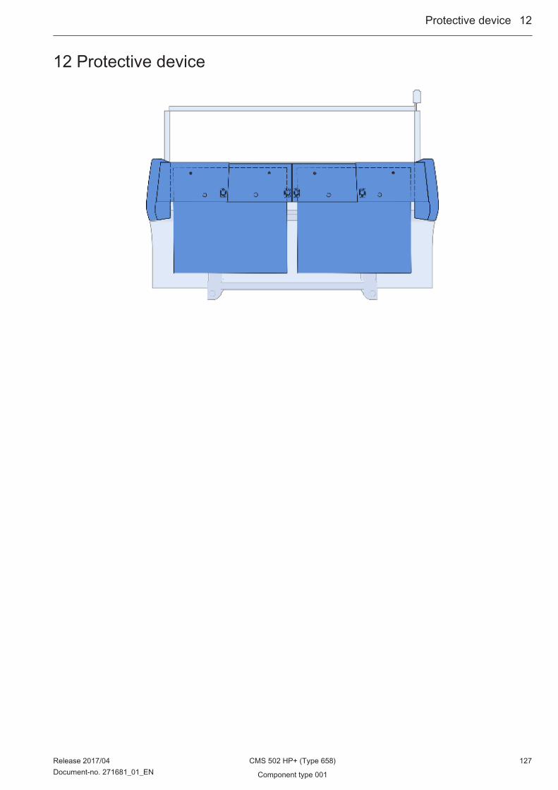
12 Protective device
Protective device ...12
Release 2017/04 CMS 502 HP+ (Type 658) 127Document-no. 271681_01_EN Component type 001

12.1 Lateral safety doorsPos Designation Id Pos Designation Id1 Safety door on the left 1 Safety door on the right
E10-18 269 784 E10-18 269 785E7-8│E6.2 269 782 E7-8│E6.2 269 783E5│E2,5.2│E3,5.2 269 780 E5│E2,5.2│E3,5.2 269 781
2 Hinge 263 939 2 Hinge 263 9393 Locking plate 219 748 3 Locking plate 219 74810 Actuator AZ 15/16 255 492 10 Actuator AZ 15/16 255 492501 Screw 6x30 265 380 501 Screw 6x30 265 380502 Screw 4x16 263 995 502 Screw 4x16 263 995506 Screw 6x20 265 379 506 Screw 6x20 265 379
12...Protective device
128 CMS 502 HP+ (Type 658) Release 2017/04
Component type 001 Document-no. 271681_01_EN

12.2 PanellingPos Designation Id Pos Designation Id1 Cover on the left complete 272 463 1-3 b Inlet type handle 251 376
1a Cover on the left 272 462 c Magnet 264 0152 Cover in the middle complete 272 465 d Stripper 219 393
2a Cover in the middle 272 464 5 Control unit panelling on the left 252 5953 Cover on the right complete 272 467 6 Control unit panelling on the right 252 585
3a Cover on the right 272 466
Protective device ...12
Release 2017/04 CMS 502 HP+ (Type 658) 129Document-no. 271681_01_EN Component type 001

12.3 Rear panelPos Designation Id. no. Pos Designation Id. no.1 Panelling at the rear complete 264 017 1a Rear panel 268 545
1b Safety sash fastener complete 243 052
12...Protective device
130 CMS 502 HP+ (Type 658) Release 2017/04
Component type 001 Document-no. 271681_01_EN
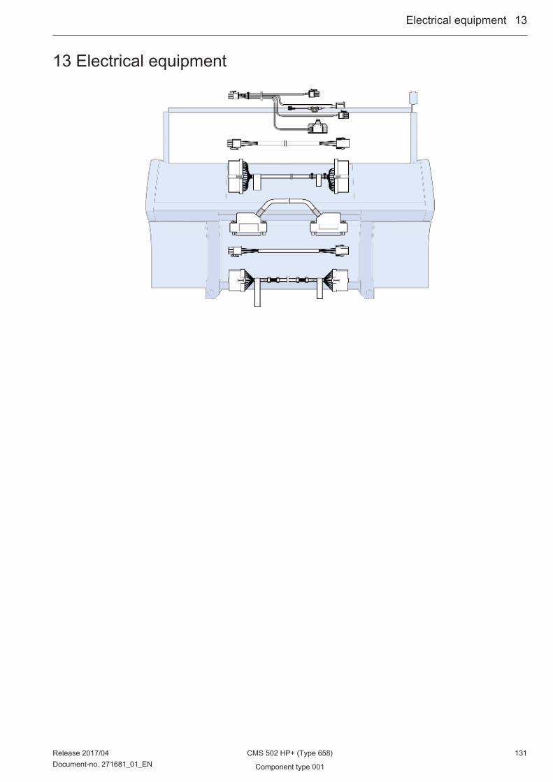
13 Electrical equipment
Electrical equipment ...13
Release 2017/04 CMS 502 HP+ (Type 658) 131Document-no. 271681_01_EN Component type 001
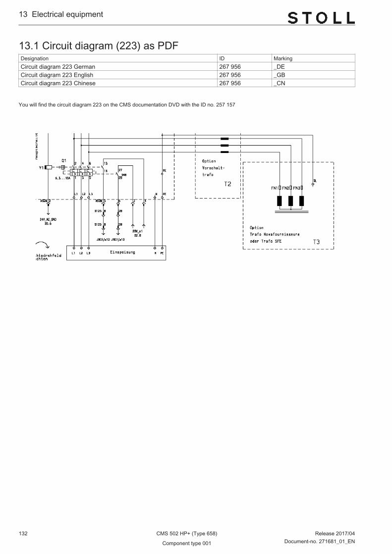
13.1 Circuit diagram (223) as PDFDesignation ID MarkingCircuit diagram 223 German 267 956 _DECircuit diagram 223 English 267 956 _GBCircuit diagram 223 Chinese 267 956 _CN
You will find the circuit diagram 223 on the CMS documentation DVD with the ID no. 257 157
13...Electrical equipment
132 CMS 502 HP+ (Type 658) Release 2017/04
Component type 001 Document-no. 271681_01_EN

Electrical equipment ...13
Release 2017/04 CMS 502 HP+ (Type 658) 133Document-no. 271681_01_EN Component type 001

13.2 Trailing cableDesignation Id Designation IdTrailing cable set 520HP 2IMP 264 937 Cable carriage at the rear XR332 420 ECO2 252 007 Cable impulse sensor OH at the rear
XR136_502 BM2264 587
Cable carriage at the rear XR333 420 ECO2 252 008 Cable impulse sensor OH at the frontXR137_502 BM2
264 588
Cable yarn carrier 420 XR161 ECO2 252 059
13...Electrical equipment
134 CMS 502 HP+ (Type 658) Release 2017/04
Component type 001 Document-no. 271681_01_EN

13.3 Cable set installation part 1Designation ID Designation IDΣ Cable installation OKC5 265 560
Cable drive motor GA 262 235 Limit switch racking OKC 3XX 240 292Cable racking motor GA 262 237
Cable resolver drive OKC5 262 236 Cable Engaging rod ECO2 252 538
Cable resolver racking EKC 270 037 Transformer cable XT7 servo 261 350
Cable fan drive 3XX OKC 240 293 Cable sensor HIAB OKC5 265 698
Cable protective device on the right OKC5 265 694 Cable protective device on the left OKC5 265 695 Cable switch auxiliary take-down OKC5 265 677
Lighting LED OKC5 265 675
Electrical equipment ...13
Release 2017/04 CMS 502 HP+ (Type 658) 135Document-no. 271681_01_EN Component type 001

13.4 Cable set installation part 2Designation ID Designation IDΣ Cable installation OKC5 265 560
Cable switch comb OKC5 262 241 Cable switch main take-down OKC5 262 240
Cable resolver comb 260 327 Cable Feed wheel on the right OKC 3XX 240 294Cable resolver HAAB 260 325
Cable power comb 260 326 Transformer cable XT9 power supply unit 261 351Cable power HAAB 260 324
Cable power auxiliary take-down OKC5 265 676 Cable supply FKE lampOKC5 266 268Cable power comb hook 260 328
Cable of comb hook switch OKC5 262 239 Cable of right coverOKC5 265 696
Transformer XT9 cable power supply unit 261 351
13...Electrical equipment
136 CMS 502 HP+ (Type 658) Release 2017/04
Component type 001 Document-no. 271681_01_EN

13.5 Cable set installation part 1, belt take-downDesignation ID Designation IDΣ Cable installation 5XX OKC5 BA 267 951
Cable drive motor GA 262 235 Lighting LED OKC5 265 675Cable racking motor GA 262 237
Cable resolver drive OKC5 262 236 Limit switch racking OKC 3XX 240 292
Cable resolver racking EKC 270 037 Cable Engaging rod ECO2 252 538
Cable fan drive 3XX OKC 240 293 Transformer cable XT7 servo 261 350
Cable protective device on the right OKC5 265 694 Cable protective device on the left OKC5 265 695
Electrical equipment ...13
Release 2017/04 CMS 502 HP+ (Type 658) 137Document-no. 271681_01_EN Component type 001

13.6 Cable set installation part 2, belt take-downDesignation ID Designation IDΣ Cable installation 5XX OKC5 BA 267 951
Cable power HAAB 260 324 Cable between switch and winding plateOKC5 BA
267 952
Cable resolver HAAB 260 325 Cable supply FKE lampOKC5 266 268
Transformer cable XT9 power supply unit 261 351 Cable Feed wheel on the right OKC 3XX 240 294
Cable feed wheel on the left 50“ OKC 240 464 Cable of right coverOKC5 265 696
13...Electrical equipment
138 CMS 502 HP+ (Type 658) Release 2017/04
Component type 001 Document-no. 271681_01_EN

14 Control electronics
Control electronics ...14
Release 2017/04 CMS 502 HP+ (Type 658) 139Document-no. 271681_01_EN Component type 001
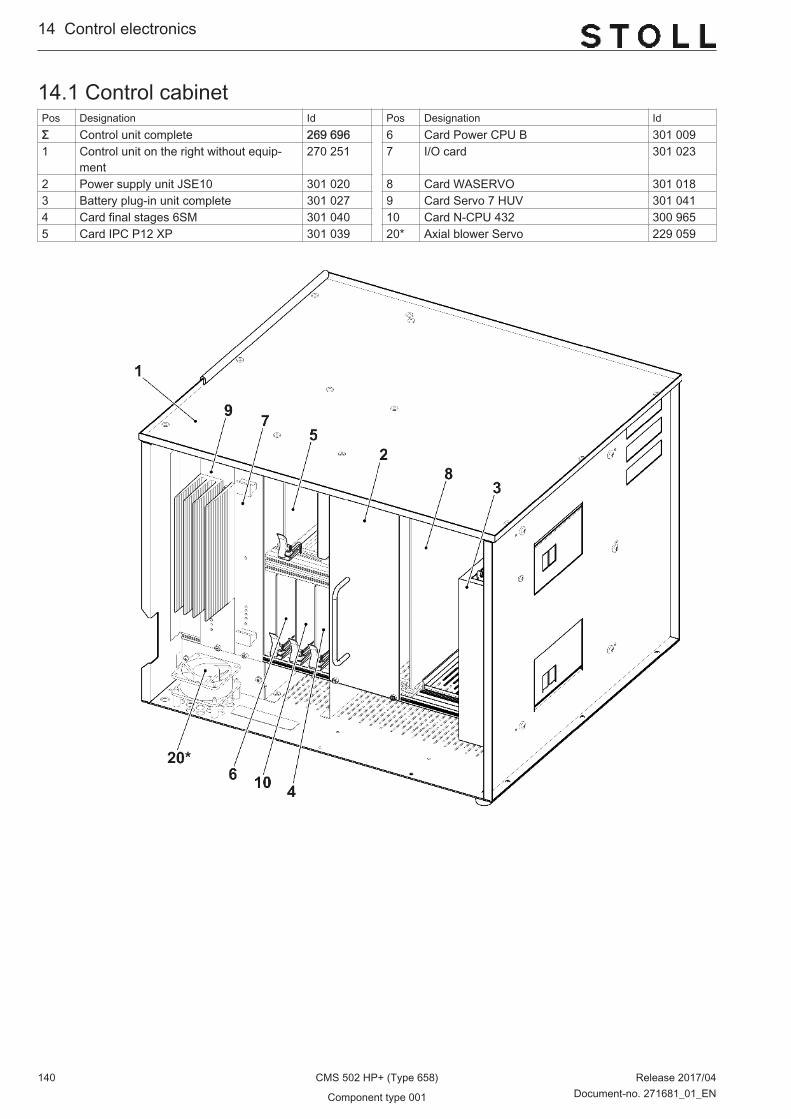
14.1 Control cabinetPos Designation Id Pos Designation IdΣ Control unit complete 269 696 6 Card Power CPU B 301 0091 Control unit on the right without equip‐
ment270 251 7 I/O card 301 023
2 Power supply unit JSE10 301 020 8 Card WASERVO 301 0183 Battery plug-in unit complete 301 027 9 Card Servo 7 HUV 301 0414 Card final stages 6SM 301 040 10 Card N-CPU 432 300 9655 Card IPC P12 XP 301 039 20* Axial blower Servo 229 059
14...Control electronics
140 CMS 502 HP+ (Type 658) Release 2017/04
Component type 001 Document-no. 271681_01_EN
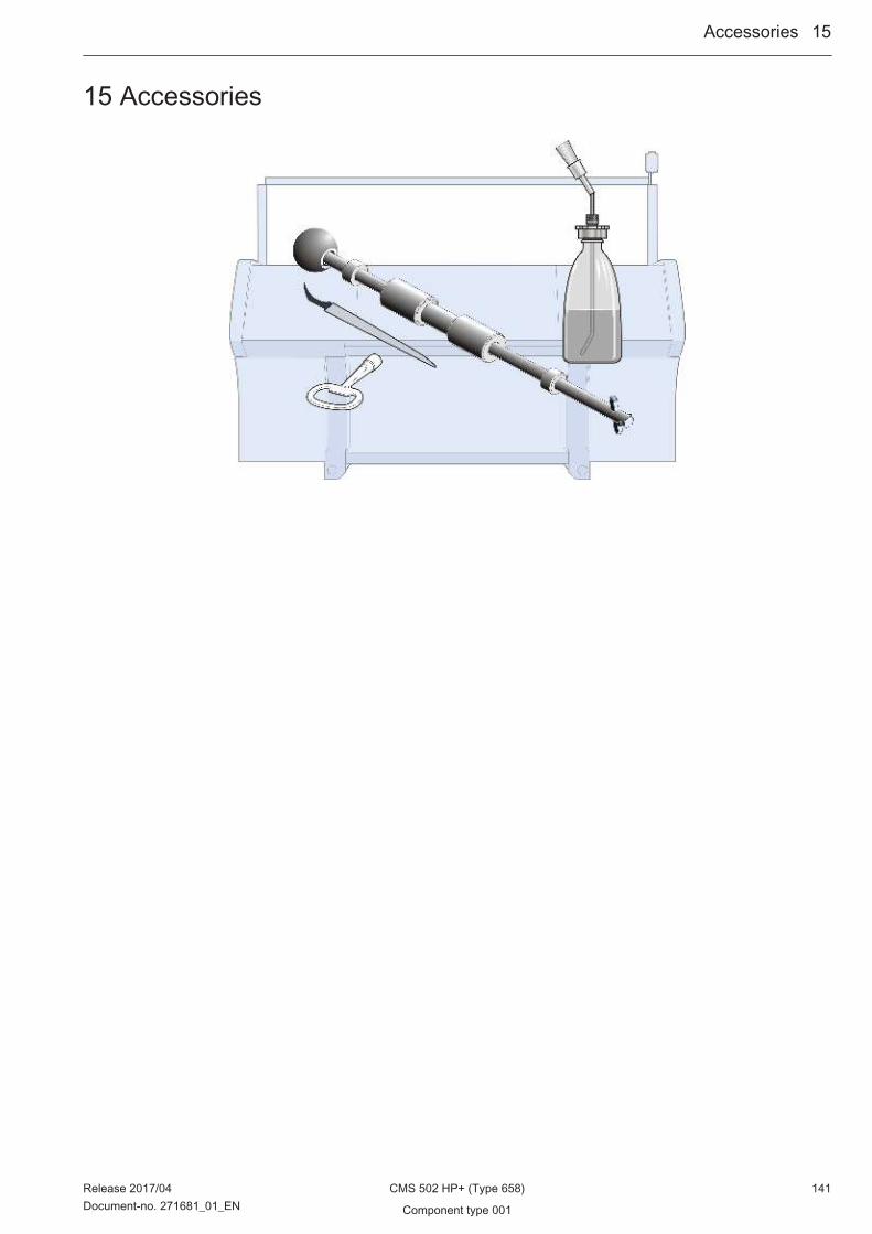
15 Accessories
Accessories ...15
Release 2017/04 CMS 502 HP+ (Type 658) 141Document-no. 271681_01_EN Component type 001
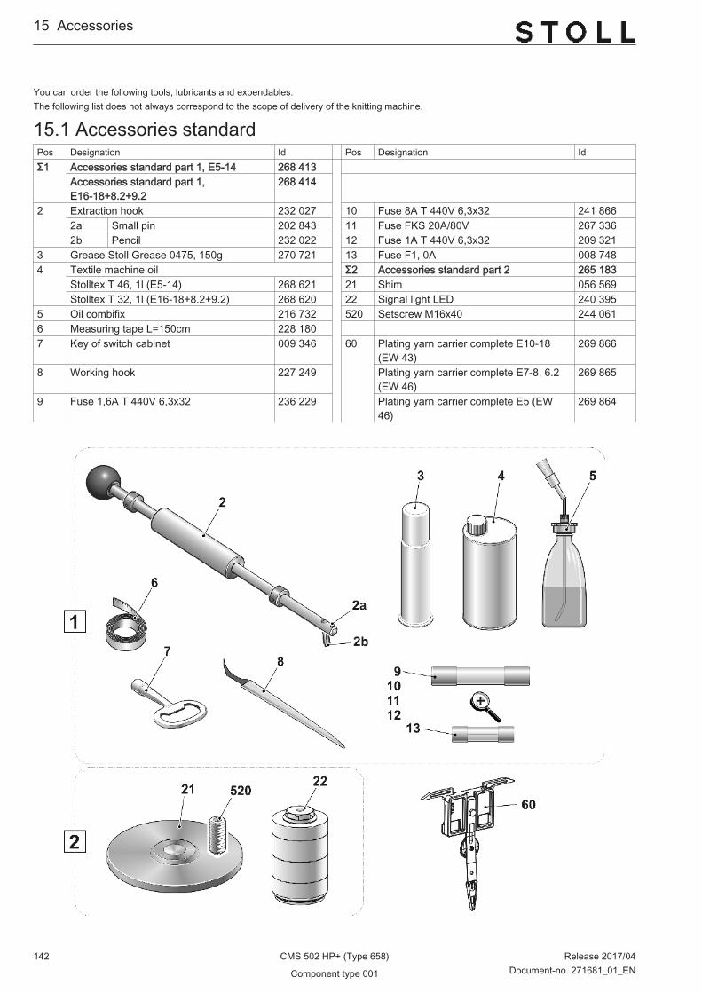
You can order the following tools, lubricants and expendables.The following list does not always correspond to the scope of delivery of the knitting machine.
15.1 Accessories standardPos Designation Id Pos Designation IdΣ1 Accessories standard part 1, E5-14 268 413
Accessories standard part 1,E16-18+8.2+9.2
268 414
2 Extraction hook 232 027 10 Fuse 8A T 440V 6,3x32 241 8662a Small pin 202 843 11 Fuse FKS 20A/80V 267 3362b Pencil 232 022 12 Fuse 1A T 440V 6,3x32 209 321
3 Grease Stoll Grease 0475, 150g 270 721 13 Fuse F1, 0A 008 7484 Textile machine oil Σ2 Accessories standard part 2 265 183
Stolltex T 46, 1l (E5-14) 268 621 21 Shim 056 569Stolltex T 32, 1l (E16-18+8.2+9.2) 268 620 22 Signal light LED 240 395
5 Oil combifix 216 732 520 Setscrew M16x40 244 0616 Measuring tape L=150cm 228 180 7 Key of switch cabinet 009 346 60 Plating yarn carrier complete E10-18
(EW 43)269 866
8 Working hook 227 249 Plating yarn carrier complete E7-8, 6.2(EW 46)
269 865
9 Fuse 1,6A T 440V 6,3x32 236 229 Plating yarn carrier complete E5 (EW46)
269 864
15...Accessories
142 CMS 502 HP+ (Type 658) Release 2017/04
Component type 001 Document-no. 271681_01_EN

15.2 Carriage of plating yarn carrierPos Designation ID Pos Designation IDΣ Plating yarn carrier complete E10-18 (EW
43)269 866 2 Shim 213 035
Plating yarn carrier complete E7-8, 6.2(EW 46)
269 865 3 FF bow E10-18 (4+5) 223 202
Plating yarn carrier complete E5 (EW 46) 269 864 FF bow E7-8, 6.2 (4+5) 212 9971 FF carriage complete E10-18 (EW 43) 257 241 FF bow E5 (4+5) 212 910
FF carriage complete E5-8 (EW 46) 244 253 3a Yarn guide star 209 2571a FF carriage E10-18 (EW 43) 257 240 3b Pan head screw M3x10 023 032
FF carriage E5-8 (EW 46) 243 881 500 Hexagon screw M5x10 020 3511b Sliding piece 212 583 1c Shim 216 143 1d Compression spring 4,0x0,55x11 021 399 1e Threaded bolt 213 399
Accessories ...15
Release 2017/04 CMS 502 HP+ (Type 658) 143Document-no. 271681_01_EN Component type 001

15...Accessories
144 CMS 502 HP+ (Type 658) Release 2017/04
Component type 001 Document-no. 271681_01_EN
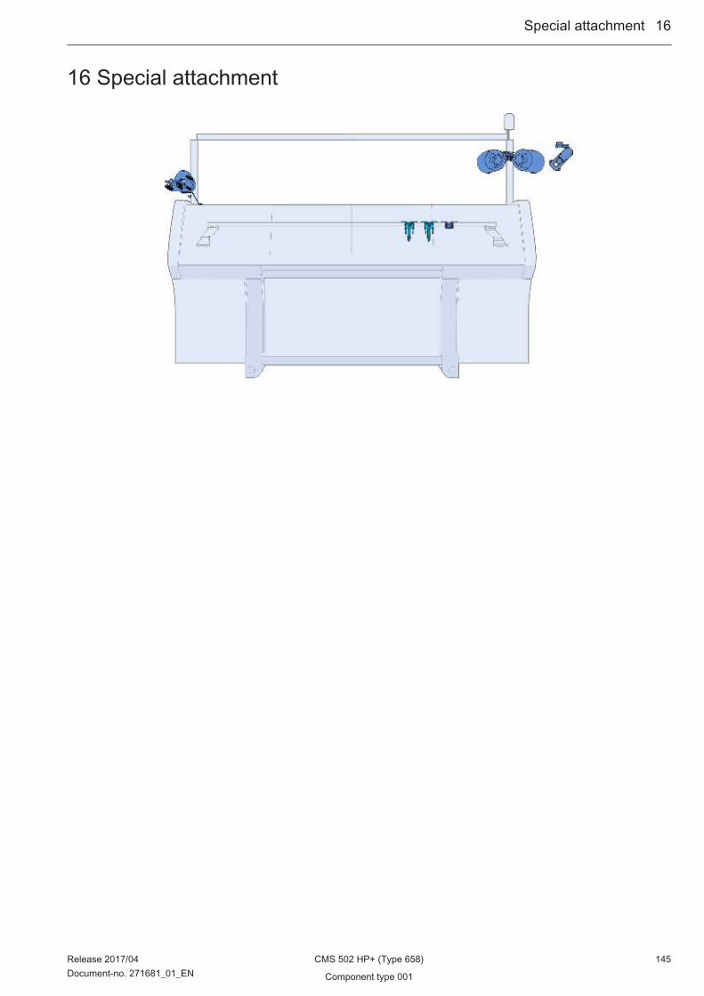
16 Special attachment
Special attachment ...16
Release 2017/04 CMS 502 HP+ (Type 658) 145Document-no. 271681_01_EN Component type 001
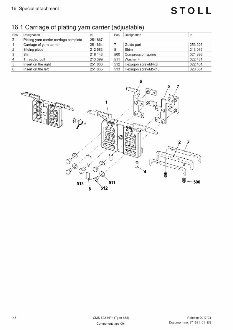
16.1 Carriage of plating yarn carrier (adjustable)Pos Designation Id Pos Designation IdΣ Plating yarn carrier carriage complete 251 867 1 Carriage of yarn carrier 251 864 7 Guide part 253 2262 Sliding piece 212 583 8 Shim 213 0353 Shim 216 143 500 Compression spring 021 3994 Threaded bolt 213 399 511 Washer 4 022 4815 Insert on the right 251 866 512 Hexagon screwM4x8 022 4616 Insert on the left 251 865 513 Hexagon screwM5x10 020 351
16...Special attachment
146 CMS 502 HP+ (Type 658) Release 2017/04
Component type 001 Document-no. 271681_01_EN

16.2 Bobbin holder on the rightPos Designation ID Pos Designation IDΣ Bobbin holder on the right 253 966 501 Pan-head screw M4x25 023 5111 Support 253 969 502 Washer 4 022 4812 Support 252 769 503 Hexagon nut M4-6 022 5363 Leaf spring 253 350 505 Washer 6 022 4314 Support right 253 348 506 Hexagon nut M6-6 022 8995 Spacer 253 349 507 Pan-head screw M4x16 023 4126 Yarn detector Massardi 226 964 508 Pan-head screw M4x12 023 0627 Clamp 228 583 509 Pan-head screw M8x16 023 1138 Slot nut 228 851 510 Pan-head screw M8x18 251 33110 Cover 253 968 511 Pan-head screw M6x30 023 45111 Holding angle 253 964 512 Serrated lock washer A4,3 022 48212 Holding angle 253 963 513 Pan-head screw M4x6 022 94613 Holding angle 253 967 514 Pan-head screw M4x10 023 45014 Cable plating 253 468 515 Cap nut M4-6 253 805
Special attachment ...16
Release 2017/04 CMS 502 HP+ (Type 658) 147Document-no. 271681_01_EN Component type 001

16.3 Yarn length measuring device on the left completePos Designation Id Pos Designation IdΣ Yarn length measuring device on the left
complete265 391
1 Yarn length measuring device on the leftcomplete
257 283 10 Operating instructions of ASCON as‐sembly
266 069
2 Cable ASCON 257 239 500 T-head bolt M8x25 022 8663 Support on the left 265 046 501 Serrated nut M8-10 023 0265 Adjustment weight 212 241 503 Cable tape 302x4,8 008 6428 DVD with operating instructions 258 391 504 Cap screw M5x12 020 1329 Holding plate 258 386 505 Washer 5 020 871
16...Special attachment
148 CMS 502 HP+ (Type 658) Release 2017/04
Component type 001 Document-no. 271681_01_EN
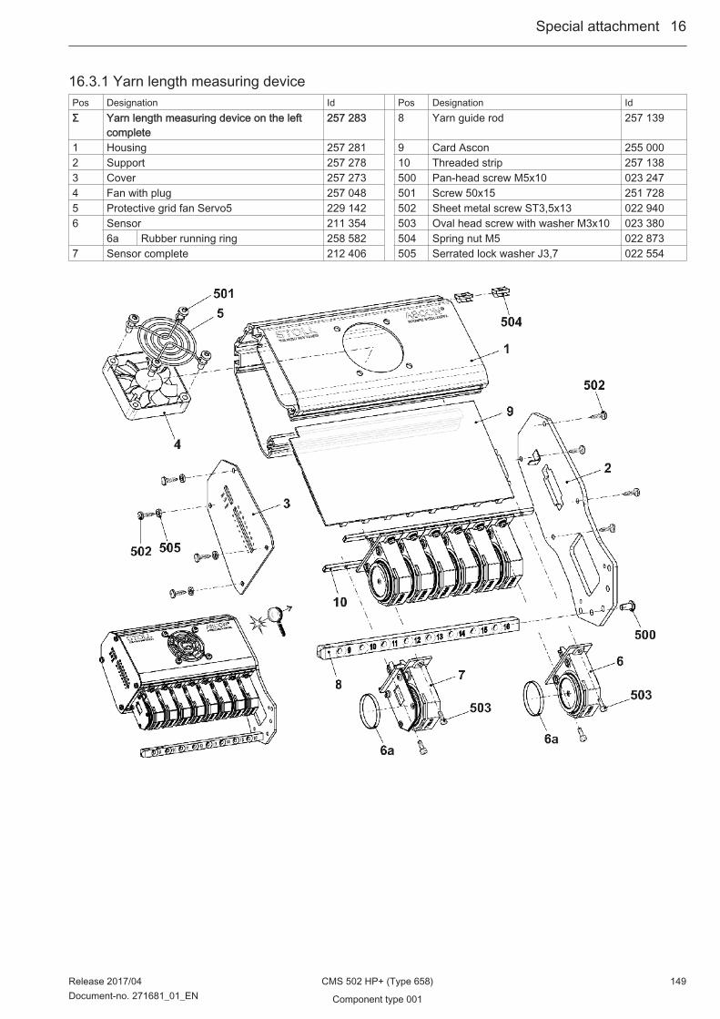
16.3.1 Yarn length measuring devicePos Designation Id Pos Designation IdΣ Yarn length measuring device on the left
complete257 283 8 Yarn guide rod 257 139
1 Housing 257 281 9 Card Ascon 255 0002 Support 257 278 10 Threaded strip 257 1383 Cover 257 273 500 Pan-head screw M5x10 023 2474 Fan with plug 257 048 501 Screw 50x15 251 7285 Protective grid fan Servo5 229 142 502 Sheet metal screw ST3,5x13 022 9406 Sensor 211 354 503 Oval head screw with washer M3x10 023 380
6a Rubber running ring 258 582 504 Spring nut M5 022 8737 Sensor complete 212 406 505 Serrated lock washer J3,7 022 554
Special attachment ...16
Release 2017/04 CMS 502 HP+ (Type 658) 149Document-no. 271681_01_EN Component type 001

16.4 Yarn length measuring device on the right completePos Designation Id Pos Designation IdΣ Yarn length measuring device on the right
complete265 392
1 Yarn length measuring device on the rightcomplete
257 282 10 Operating instructions of ASCON as‐sembly
266 069
2 Cable ASCON 257 239 500 T-head bolt M8x25 022 8663 Support right 265 045 501 Serrated nut M8-10 023 0265 Adjustment weight 212 241 503 Cable tape 302x4,8 008 6428 DVD with operating instructions 258 391 504 Cap screw M5x12 020 1329 Holding plate 258 386 505 Washer 5 020 871
16...Special attachment
150 CMS 502 HP+ (Type 658) Release 2017/04
Component type 001 Document-no. 271681_01_EN
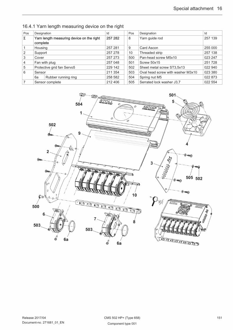
16.4.1 Yarn length measuring device on the rightPos Designation Id Pos Designation IdΣ Yarn length measuring device on the right
complete257 282 8 Yarn guide rod 257 139
1 Housing 257 281 9 Card Ascon 255 0002 Support 257 278 10 Threaded strip 257 1383 Cover 257 273 500 Pan-head screw M5x10 023 2474 Fan with plug 257 048 501 Screw 50x15 251 7285 Protective grid fan Servo5 229 142 502 Sheet metal screw ST3,5x13 022 9406 Sensor 211 354 503 Oval head screw with washer M3x10 023 380
6a Rubber running ring 258 582 504 Spring nut M5 022 8737 Sensor complete 212 406 505 Serrated lock washer J3,7 022 554
Special attachment ...16
Release 2017/04 CMS 502 HP+ (Type 658) 151Document-no. 271681_01_EN Component type 001
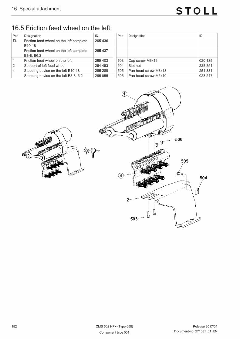
16.5 Friction feed wheel on the leftPos Designation ID Pos Designation IDΣL Friction feed wheel on the left complete
E10-18265 436
Friction feed wheel on the left completeE3-8, E6.2
265 437
1 Friction feed wheel on the left 269 403 503 Cap screw M6x16 020 1352 Support of left feed wheel 264 453 504 Slot nut 228 8514 Stopping device on the left E10-18 265 289 505 Pan head screw M8x18 251 331
Stopping device on the left E3-8, 6.2 265 055 506 Pan head screw M5x10 023 247
16...Special attachment
152 CMS 502 HP+ (Type 658) Release 2017/04
Component type 001 Document-no. 271681_01_EN
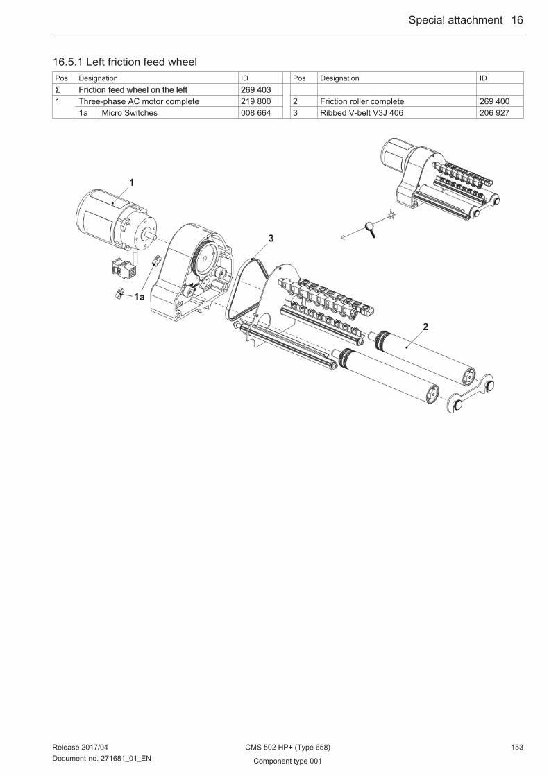
16.5.1 Left friction feed wheelPos Designation ID Pos Designation IDΣ Friction feed wheel on the left 269 403 1 Three-phase AC motor complete 219 800 2 Friction roller complete 269 400
1a Micro Switches 008 664 3 Ribbed V-belt V3J 406 206 927
Special attachment ...16
Release 2017/04 CMS 502 HP+ (Type 658) 153Document-no. 271681_01_EN Component type 001
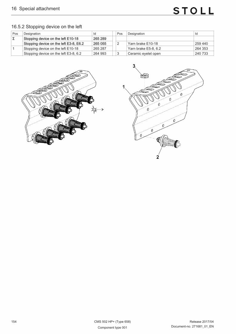
16.5.2 Stopping device on the leftPos Designation Id Pos Designation IdΣ Stopping device on the left E10-18 265 289
Stopping device on the left E3-8, E6.2 265 055 2 Yarn brake E10-18 259 4401 Stopping device on the left E10-18 265 287 Yarn brake E5-8, 6.2 264 353
Stopping device on the left E3-8, 6.2 264 993 3 Ceramic eyelet open 240 733
16...Special attachment
154 CMS 502 HP+ (Type 658) Release 2017/04
Component type 001 Document-no. 271681_01_EN

16.6 Storage feed wheel MSF-3 complete E10-18Pos Designation ID NoteΣ Assembly kit MSF-3 completeE10-18 EP 268 499 Please order the MSF-3 spare parts at:
MEMMINGER-IRO GMBHJakob-Mutz-Strasse 7
D-72280 Dornstetten
Tel.: +49 (0)7443 281-0Fax: +49 (0)7443 281-101
The item no. and the designation for the MSF-3spare parts can be found in the enclosed assem‐bling instructions of the company MEMMINGER-IRO.
1 Assembly kit MSF-3 complete single-phase 267 3592 Support yarn brake 502 complete 260 7273 Stopping device on the right complete E10-18 265 5995* Storage feed wheel 259 604
Special attachment ...16
Release 2017/04 CMS 502 HP+ (Type 658) 155Document-no. 271681_01_EN Component type 001

16.7 Sanding Paper BrakePos Designation Id Pos Designation IdΣ Conversion kit sanding paper brake 257 674 1 Axle complete 257 509 2 Shaft 241 318
1a Shaft 241 318 3 Support sanding paper brake 257 5861b Adjusting part 257 508 4 Support sanding paper brake on the left 257 626510 Compression spring
0,32x2,51x14,20237 444 500 Screw KB 60x20 237 682
511 Setscrew M4x6 022 955 501 Setscrew M4x5 023 088
16...Special attachment
156 CMS 502 HP+ (Type 658) Release 2017/04
Component type 001 Document-no. 271681_01_EN
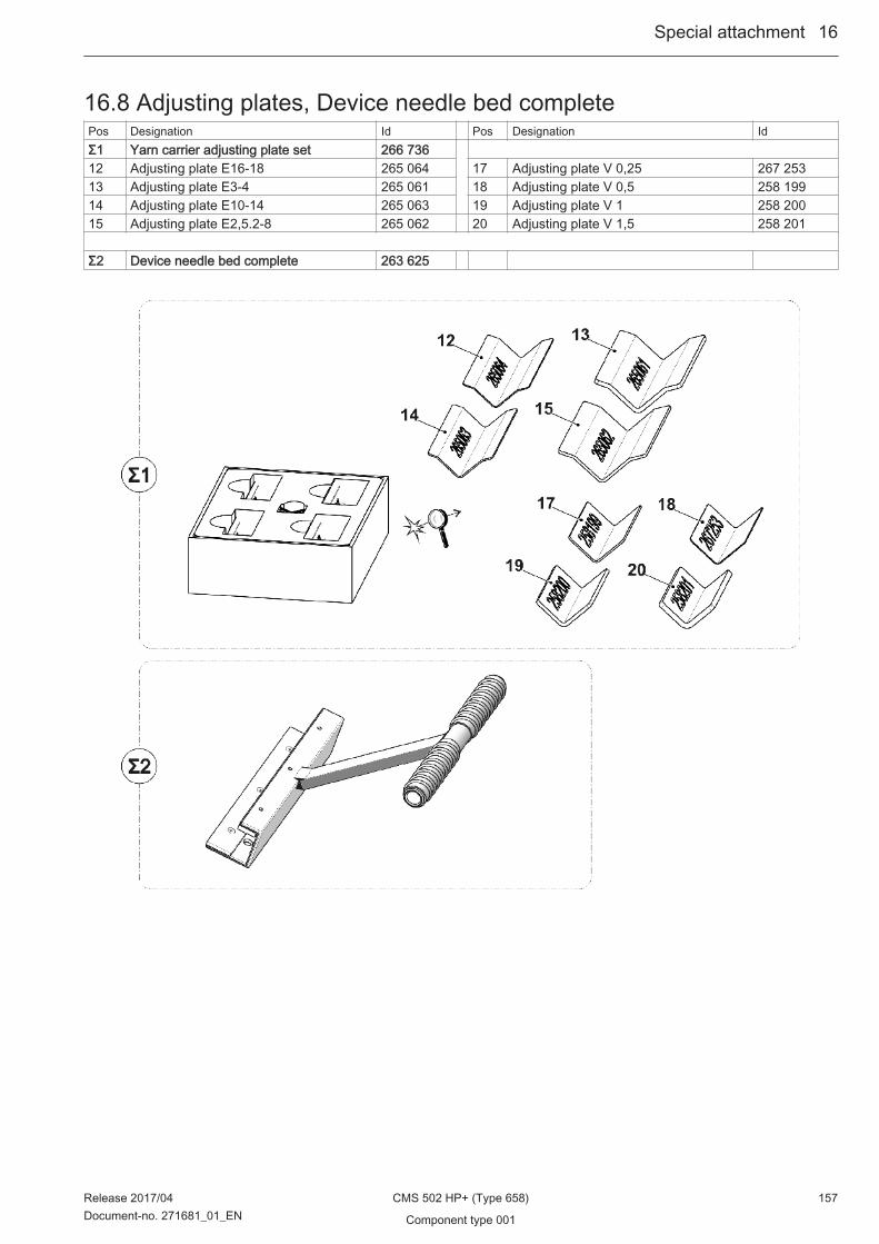
16.8 Adjusting plates, Device needle bed completePos Designation Id Pos Designation IdΣ1 Yarn carrier adjusting plate set 266 736 12 Adjusting plate E16-18 265 064 17 Adjusting plate V 0,25 267 25313 Adjusting plate E3-4 265 061 18 Adjusting plate V 0,5 258 19914 Adjusting plate E10-14 265 063 19 Adjusting plate V 1 258 20015 Adjusting plate E2,5.2-8 265 062 20 Adjusting plate V 1,5 258 201 Σ2 Device needle bed complete 263 625
Special attachment ...16
Release 2017/04 CMS 502 HP+ (Type 658) 157Document-no. 271681_01_EN Component type 001

16...Special attachment
158 CMS 502 HP+ (Type 658) Release 2017/04
Component type 001 Document-no. 271681_01_EN