close control units with remote air condenser ed.x kc · ed.x kc 7 close control units with remote...
TRANSCRIPT
ED
.X K
c
6
CLOSE CONTROL UNITS WITH REMOTE AIR CONDENSER
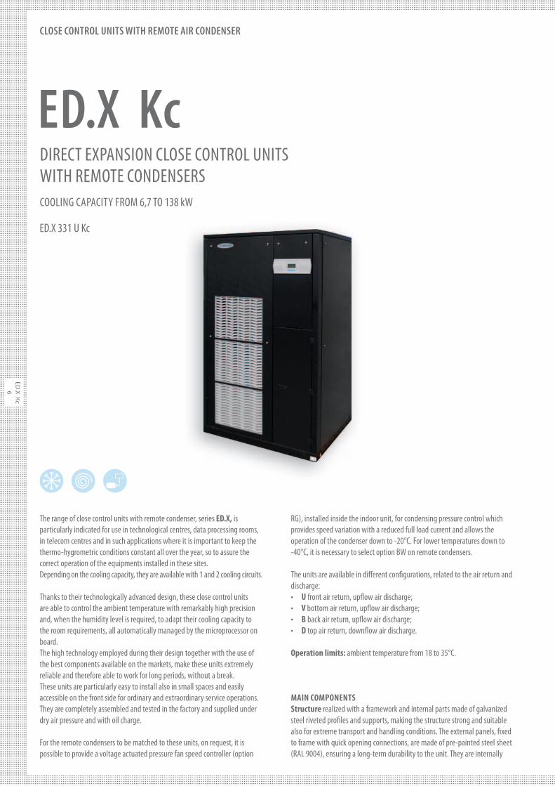
The range of close control units with remote condenser, series ED.X, is particularly indicated for use in technological centres, data processing rooms, in telecom centres and in such applications where it is important to keep the thermo-hygrometric conditions constant all over the year, so to assure the correct operation of the equipments installed in these sites.Depending on the cooling capacity, they are available with 1 and 2 cooling circuits.
Thanks to their technologically advanced design, these close control units are able to control the ambient temperature with remarkably high precision and, when the humidity level is required, to adapt their cooling capacity to the room requirements, all automatically managed by the microprocessor on board.The high technology employed during their design together with the use of the best components available on the markets, make these units extremely reliable and therefore able to work for long periods, without a break.These units are particularly easy to install also in small spaces and easily accessible on the front side for ordinary and extraordinary service operations.They are completely assembled and tested in the factory and supplied under dry air pressure and with oil charge.
For the remote condensers to be matched to these units, on request, it is possible to provide a voltage actuated pressure fan speed controller (option
RG), installed inside the indoor unit, for condensing pressure control which provides speed variation with a reduced full load current and allows the operation of the condenser down to -20°C. For lower temperatures down to -40°C, it is necessary to select option BW on remote condensers.
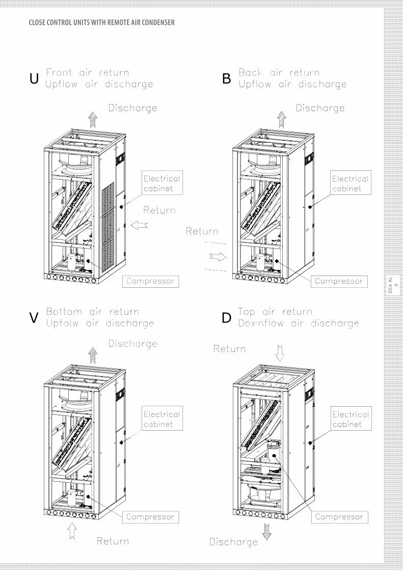
The units are available in di" erent con# gurations, related to the air return and discharge:· U front air return, up$ ow air discharge;· V bottom air return, up$ ow air discharge;· B back air return, up$ ow air discharge;· D top air return, down$ ow air discharge.
Operation limits: ambient temperature from 18 to 35°C.
MAIN COMPONENTS
Structure realized with a framework and internal parts made of galvanized steel riveted pro# les and supports, making the structure strong and suitable also for extreme transport and handling conditions. The external panels, # xed to frame with quick opening connections, are made of pre-painted steel sheet (RAL 9004), ensuring a long-term durability to the unit. They are internally
ED.X KcDIRECT EXPANSION CLOSE CONTROL UNITSWITH REMOTE CONDENSERS
COOLING CAPACITY FROM 6,7 TO 138 kW
ED.X 331 U Kc
ED
.X
Kc
7
CLOSE CONTROL UNITS WITH REMOTE AIR CONDENSER
insulated with self-extinguishing sound-proo#ng material (class HF1 – UL94) reducing the overall sound level of the unit. On request (option IS1), it is available the sound-proo#ng insulation with class 1 material in conformity to the main European regulations in force. All the front and side panels can be dismantled so to allow an easy access to the main components. Moreover, the front of the unit is provided with double panels and inspection window (not available for version U), suitably arranged to let the unit work also with open panels during technical interventions, to allow more accurate regulations and more quick timing for ordinary and extraordinary service operations.
High-e!ciency scroll compressor (EER > 3.2 at ARI conditions), with low sound level, internal heat protection, installed on rubber vibration dampers, supplied with crankcase heater.In the case of 2 circuit units, in case of problem on one of the circuit, the 50% operation of the unit is anyway granted.
Single-inlet and backward curved centrifugal fans made of high-performance composite material, directly coupled to a three-phase electrical motor with IP54 Class F protection and provided with a thermal protection inside the motor winding. The fans are #xed on suitable supports reducing the transmission of vibration to the frame and the impeller is statically and dynamically balanced with long-life bearings. It is possible to regulate the fan speed by means of an autotransformer and to adjust their air $ow to the head pressure requested on site. It is clear that a higher fans speed rotation involves an increase in the sound level of the unit.All the units are equipped with low air$ow and clogged #lter alarms which, by means of di"erential pressure switches, stop the unit operation in case of fans problems and give a signal on microprocessor for replacement respectively.
Direct expansion evaporating coil, realized with copper tube and aluminium #ns, it is suitably sized with a wide exchange surface and a low air crossing speed so to allow a remarkable heat exchange and reduce the pressure drops on the air side. It is provided with a hydrophilic treatment to reduce the surface tension between water and metal surface, promoting #lm condensation and avoiding the risk of condensing drops outside the drain tray.
Condensing drain tray, made in corrosion proof peraluman, placed underneath the evaporating coil, it is provided with a $exible pipe for condensing water discharge.
Washable and self-extinguishing air "lters E&ciency G4 – of pleated type, they are made of synthetic #bre and are contained in a suitable metal frame. Their pleated arrangement, with a wide surface area, ensures a higher #ltering e&ciency and low pressure drops.
Cooling circuit made of: electronic thermostatic valve, sight glass, dehydrating #lter, safety device, high pressure switch, solenoid valve, liquid receiver, shut-o" valve on compressor discharge and on liquid line. Thanks to the electronic thermostatic valve, there is a more accurate regulation of the evaporating pressure/temperature in all working conditions, with superheating at a constant value.
Electric board in compliance with CE norms, protected by a panel is separated by the air $ow and is provided with main switch, automatic switches, remote control switches, motor protection switches, low-tension auxiliary circuits and terminal board for free contacts and remote general alarm, magnetothermic switches for humidi#er and electric heaters (when installed).
Unit management microprocessor installed inside the electrical board,
complete with hour counter and electronic card to program the switch-over and rotation between to units, after a pre-set time. On this purpose, in case of order, the information necessary for programming must be clearly de#ned. It allows 3 languages display reading, a detailed description of parameters, the possibility to manage up to 8 units, to manage non standard communication protocols, a quickest access to the program, the control of the electronic thermostatic valve and of the humidi#er, the control of modulating valves.
ACCESSORIES
AA Flooding detector: placed in the down$ow units, it is already wired and detects water in the false $oor.AE Electrical power supply di#erent from standard: mainly, 230V three-phase, 460V three-phase. Frequency 50/60 Hz.AL Smoke alarm: it consists of a sensor detecting smoke inside the unit and activating an alarm signal which stops the fans.B Adjustable base-frame from 170mm to max 600mm for installation on raised $oors. It is provided with adjustable feet.BC Hot water coil: one-row or 2-row water coil, placed after the cooling coil for the re-heating and/or the heating of treated air. Provided with modulating actuator and with three-way valve, it is controlled by the microprocessor on board. This option is priority when requested with the electric heaters RE option. (Alternative to BG and not available with REM).BG Hot gas coil: placed after the cooling coil, it makes the re-heating of the treated air and is provided with a 3-way valve (ON/OFF) controlled by the microprocessor on board. It is available only with the dehumidi#cation control (options DH) (Alternative to BC and not available with HG).BN Base-frame with conveyor: it is provided with a suitable conveyor facilitating the air $ow and remarkably reducing the pressure drop in case of horizontal air $ow. It is adjustable in height from min 400mm to max 800mm. (Only for D version).BS Base-frame with ON/OFF damper: it is equipped with an ON/OFF motorized damper. This device prevents the air return from the unit when it is not working or in the case some units are working near to it. Available only for D version; for other versions, being a special execution, please contact our Sales Dept.BSN Base-frame with conveyor and ON/OFF damper: a single base- frame with both options BS and BN so to optimize e&ciency and overall dimensions.CI Soundproo"ng jacket on compressors: made of soundproo#ng material, wrapped all around compressors so to further reduce the overall sound level of the unit.CS Compressors inrush counter: Electromechanical device positioned inside the electrical board, recording the total inrush starts of compressors.DH Dehumidi"cation control system: managed by microprocessor, through the electronic thermostatic valves, it operates on two parameters, ensuring that the dehumidi#cation process is carried out with a constant air $ow, without partializing the evaporating coil. This will optimize the air distribution throughout the room.DP Internal double panels: for shutting o" the compartments a"ected by the air $ow, they are made from pre-painted and galvanized steel plate, ensuring reduction in the noise transmitted through the panels and a better air tightness even without the external panels so that the access is guaranteed with the doors open during service operation.
ED
.X K
c
8
CLOSE CONTROL UNITS WITH REMOTE AIR CONDENSER
EC-LP&HP Single-inlet EC (electronically commutated) centrifugal
fans with backward curved blade (LP not available for D version): made of high-performance composite material, directly coupled to a three-phase electrical rotor with IP54 protection grade, they have the possibility of a continuous regulation of the speed by means of 10V signal, sent and integrated to the control. The fans are #xed on suitable supports reducing the transmission of vibration to the frame and the impeller is statically and dynamically balanced with long-life bearings. Thanks to their technology, the EC fans ensures a lower electrical absorption and sound level, if compared to the traditional centrifugal fans. It is possible to adjust their air $ow to the head pressure requested on site. In case of IT electrical supplies,
please contact our Sales Dept.
F5-F6-F7-F9 Higher e!ciency air "lters: pleated #lters, supplied as an alternative to standard G4 #lters.FR Spare "lter kit G4 as a replacement to the ones on board of the unit.H Humidi"er of immersed-electrode type for the modulating production of steam. It is made by a steam cylinder, by a steam distributor, by water inlet and outlet valves and by a maximum level probe. The microprocessor on board indicates when the steam cylinder needs to be replaced. It is electrically protected by a magnetothermic switch.HG Hot gas by-pass: it is a mechanical device for modulating the cooling capacity, so to reduce the ON/OFF of compressors and therefore to wait for the re-starting timing, with in$uence on condensing temperature. It is not available for sizes 1, 2 and 3 and with options BG and DH.IE Fumigated wooden crate packing: available on request for critical transports, so to assure a suitable protection to the unit.IH RS 485 serial interface: electronic card to be connected to microprocessor, to allow communication between the units and a Carel supervision system. It is possible to fully control the unit from remote. For connection to other supervision systems, the protocol of the controlled parameters is available on request.IM Seawood packing: fumigated seawood case and protection bag with hygroscopic salts, suitable for long sea transports.IP Magnetothermic switches for auxiliary circuits: when required, they replace the fuses, as a protection of the auxiliary circuits.IS1 Class 1 insulating material in conformity to the main European regulations in force.MF Phase monitor: electronic device controlling the correct sequence and/or the eventual lack of one of the 3 phases, switching o" the unit if necessary.MN Lack of neutral wire for 400/3/50 power supply: unit general power supply without neutral wire.MP Oversized microprocessor: in additional to the standard microprocessor, it allows more languages display reading (maximum 5), it has an increased hardware so to allow the managing of more inputs and outputs for the control of on board installed components (Already included on two circuit units).PB Condensing water pump: micro pump discharging the condensing water produced by the unit, it is factory installed.PBH Condensing water and humidi"er discharge pump: pump discharging the condensing water produced by the unit and the humidi#er discharge water, it is factory installed.PL Distribution plenum with front grid and a double raw of adjustable #ns for a better air distribution (for versions U,V,B and not available with options ST and STM).PQ Remote display: remote terminal, allowing to display the temperature and humidity values detected by probes, the alarm digital inputs, the outputs and the remote ON/OFF of the unit, to change and
program of the parameters, the sound signal and the display of the present alarms.PR Fresh air inlet: external fresh air inlet with #lter, placed on side (standard on the left side), with circular connection (Ø 100 mm).RE Electrical heaters: made in aluminium and installed after the cooling coil, for re-heating and/or heating of the treated air. The heating capacity is split on 3 steps max, so to reduce the energy absorption. They are controlled by the microprocessor on board and electrically protected by a magnetothermic switch.REM Oversized Electrical heaters.
RF Rephasing condensers (available for compressors only): electrical device for rephasing the compressors charge at power factor cosΦ ≥0,9.RV Personalized frame painting in RAL colour.
SL Main switch with external padlock.
ST Manual calibration damper, in galvanized steel plate with opposed- movement #ns. Through the manual control, it is possible to accurately regulate the air $ow. (Alternative to STM and not available with option PL).STM Motorized calibration damper, in galvanized steel plate with opposed-movement #ns. Through the modulating control (0-10V), it is possible to accurately regulate the air $ow. (Alternative to ST and not available with option PL) SV Gravity overpressure damper for ducted units, to prevent the air return when the units are not operating, where several units are installed in the same room. Available for U,V,B versions; for D version, being a special execution, please contact our Sales Dept.TS Touch screen graphic terminal designed to simplify user interface with the unit controller. It allows the set-point #xing, the alarm reading, the graphic display of the main controlled parameters in real time (suitable for download on USB interface) and possibility of set-point scheduling. The 4.3”, 65.000 colours and 480x422 resolution display, being a dedicated terminal for the end user, does not allow to change the basic con#guration of the unit.WG WebGate device for interfacing to BMS with SNMP or TCP/IP protocols. Only available with option IH.
ED
.X
Kc
9
CLOSE CONTROL UNITS WITH REMOTE AIR CONDENSER
ED
.X K
c
10
CLOSE CONTROL UNITS WITH REMOTE AIR CONDENSER
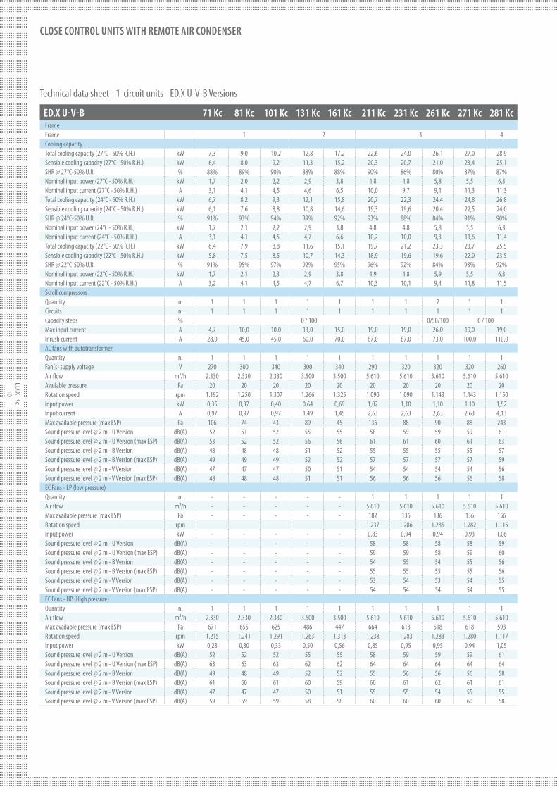
Technical data sheet - 1-circuit units - ED.X U-V-B Versions
ED.X U-V-B 71 Kc 81 Kc 101 Kc 131 Kc 161 Kc 211 Kc 231 Kc 261 Kc 271 Kc 281 Kc
FrameFrame 1 2 3 4Cooling capacityTotal cooling capacity (27°C - 50% R.H.) kW 7,3 9,0 10,2 12,8 17,2 22,6 24,0 26,1 27,0 28,9Sensible cooling capacity (27°C - 50% R.H.) kW 6,4 8,0 9,2 11,3 15,2 20,3 20,7 21,0 23,4 25,1SHR @ 27°C-50% U.R. % 88% 89% 90% 88% 88% 90% 86% 80% 87% 87%Nominal input power (27°C - 50% R.H.) kW 1,7 2,0 2,2 2,9 3,8 4,8 4,8 5,8 5,5 6,3Nominal input current (27°C - 50% R.H.) A 3,1 4,1 4,5 4,6 6,5 10,0 9,7 9,1 11,3 11,3Total cooling capacity (24°C - 50% R.H.) kW 6,7 8,2 9,3 12,1 15,8 20,7 22,3 24,4 24,8 26,8Sensible cooling capacity (24°C - 50% R.H.) kW 6,1 7,6 8,8 10,8 14,6 19,3 19,6 20,4 22,5 24,0SHR @ 24°C-50% U.R. % 91% 93% 94% 89% 92% 93% 88% 84% 91% 90%Nominal input power (24°C - 50% R.H.) kW 1,7 2,1 2,2 2,9 3,8 4,8 4,8 5,8 5,5 6,3Nominal input current (24°C - 50% R.H.) A 3,1 4,1 4,5 4,7 6,6 10,2 10,0 9,3 11,6 11,4Total cooling capacity (22°C - 50% R.H.) kW 6,4 7,9 8,8 11,6 15,1 19,7 21,2 23,3 23,7 25,5Sensible cooling capacity (22°C - 50% R.H.) kW 5,8 7,5 8,5 10,7 14,3 18,9 19,6 19,6 22,0 23,5SHR @ 22°C-50% U.R. % 91% 95% 97% 92% 95% 96% 92% 84% 93% 92%Nominal input power (22°C - 50% R.H.) kW 1,7 2,1 2,3 2,9 3,8 4,9 4,8 5,9 5,5 6,3Nominal input current (22°C - 50% R.H.) A 3,2 4,1 4,5 4,7 6,7 10,3 10,1 9,4 11,8 11,5Scroll compressorsQuantity n. 1 1 1 1 1 1 1 2 1 1Circuits n. 1 1 1 1 1 1 1 1 1 1Capacity steps % 0 / 100 0/50/100 0 / 100Max input current A 4,7 10,0 10,0 13,0 15,0 19,0 19,0 26,0 19,0 19,0Inrush current A 28,0 45,0 45,0 60,0 70,0 87,0 87,0 73,0 100,0 110,0AC fans with autotransformerQuantity n. 1 1 1 1 1 1 1 1 1 1Fan(s) supply voltage V 270 300 340 300 340 290 320 320 320 260Air $ow m³/h 2.330 2.330 2.330 3.500 3.500 5.610 5.610 5.610 5.610 5.610Available pressure Pa 20 20 20 20 20 20 20 20 20 20Rotation speed rpm 1.192 1.250 1.307 1.266 1.325 1.090 1.090 1.143 1.143 1.150Input power kW 0,35 0,37 0,40 0,64 0,69 1,02 1,10 1,10 1,10 1,52Input current A 0,97 0,97 0,97 1,49 1,45 2,63 2,63 2,63 2,63 4,13Max available pressure (max ESP) Pa 106 74 43 89 45 136 88 90 88 243Sound pressure level @ 2 m - U Version dB(A) 52 51 52 55 55 58 59 59 59 61Sound pressure level @ 2 m - U Version (max ESP) dB(A) 53 52 52 56 56 61 61 60 61 63Sound pressure level @ 2 m - B Version dB(A) 48 48 48 51 52 55 55 55 55 57Sound pressure level @ 2 m - B Version (max ESP) dB(A) 49 49 49 52 52 57 57 57 57 59Sound pressure level @ 2 m - V Version dB(A) 47 47 47 50 51 54 54 54 54 56Sound pressure level @ 2 m - V Version (max ESP) dB(A) 48 48 48 51 51 56 56 56 56 58EC Fans - LP (low pressure)Quantity n. - - - - - 1 1 1 1 1Air $ow m³/h - - - - - 5.610 5.610 5.610 5.610 5.610Max available pressure (max ESP) Pa - - - - - 182 136 136 136 156Rotation speed rpm 1.237 1.286 1.285 1.282 1.115Input power kW - - - - - 0,83 0,94 0,94 0,93 1,06Sound pressure level @ 2 m - U Version dB(A) - - - - - 58 58 58 58 59Sound pressure level @ 2 m - U Version (max ESP) dB(A) - - - - - 59 59 58 59 60Sound pressure level @ 2 m - B Version dB(A) - - - - - 54 55 54 55 56Sound pressure level @ 2 m - B Version (max ESP) dB(A) - - - - - 55 55 55 55 56Sound pressure level @ 2 m - V Version dB(A) - - - - - 53 54 53 54 55Sound pressure level @ 2 m - V Version (max ESP) dB(A) - - - - - 54 54 54 54 55EC Fans - HP (High pressure)Quantity n. 1 1 1 1 1 1 1 1 1 1Air $ow m³/h 2.330 2.330 2.330 3.500 3.500 5.610 5.610 5.610 5.610 5.610Max available pressure (max ESP) Pa 671 655 625 486 447 664 618 618 618 593Rotation speed rpm 1.215 1.241 1.291 1.263 1.313 1.238 1.283 1.283 1.280 1.117Input power kW 0,28 0,30 0,33 0,50 0,56 0,85 0,95 0,95 0,94 1,05Sound pressure level @ 2 m - U Version dB(A) 52 52 52 55 55 58 59 59 59 61Sound pressure level @ 2 m - U Version (max ESP) dB(A) 63 63 63 62 62 64 64 64 64 64Sound pressure level @ 2 m - B Version dB(A) 49 48 49 52 52 55 56 56 56 58Sound pressure level @ 2 m - B Version (max ESP) dB(A) 61 60 61 60 59 60 61 62 61 61Sound pressure level @ 2 m - V Version dB(A) 47 47 47 50 51 55 55 54 55 55Sound pressure level @ 2 m - V Version (max ESP) dB(A) 59 59 59 58 58 60 60 60 60 58
ED
.X
Kc
11
CLOSE CONTROL UNITS WITH REMOTE AIR CONDENSER
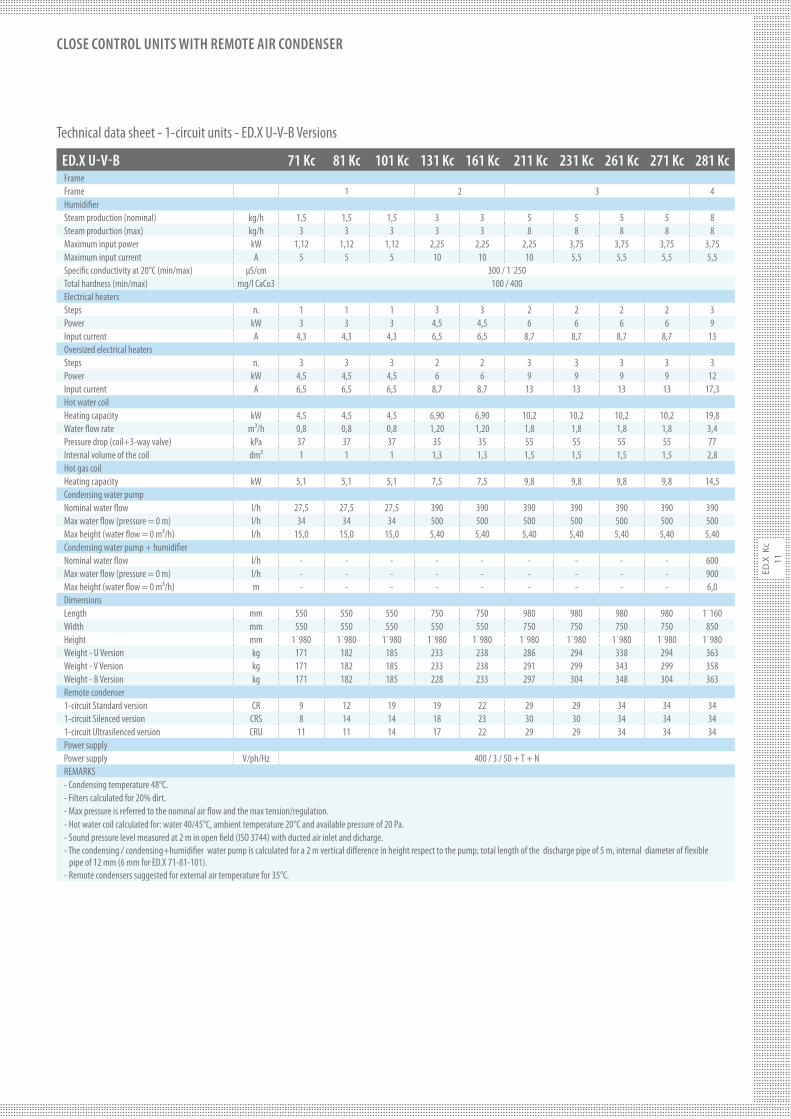
Technical data sheet - 1-circuit units - ED.X U-V-B Versions
ED.X U-V-B 71 Kc 81 Kc 101 Kc 131 Kc 161 Kc 211 Kc 231 Kc 261 Kc 271 Kc 281 Kc
FrameFrame 1 2 3 4Humidi#erSteam production (nominal) kg/h 1,5 1,5 1,5 3 3 5 5 5 5 8Steam production (max) kg/h 3 3 3 3 3 8 8 8 8 8Maximum input power kW 1,12 1,12 1,12 2,25 2,25 2,25 3,75 3,75 3,75 3,75Maximum input current A 5 5 5 10 10 10 5,5 5,5 5,5 5,5Speci#c conductivity at 20°C (min/max) µS/cm 300 / 1˙250Total hardness (min/max) mg/l CaCo3 100 / 400Electrical heatersSteps n. 1 1 1 3 3 2 2 2 2 3Power kW 3 3 3 4,5 4,5 6 6 6 6 9Input current A 4,3 4,3 4,3 6,5 6,5 8,7 8,7 8,7 8,7 13Oversized electrical heatersSteps n. 3 3 3 2 2 3 3 3 3 3Power kW 4,5 4,5 4,5 6 6 9 9 9 9 12Input current A 6,5 6,5 6,5 8,7 8,7 13 13 13 13 17,3Hot water coilHeating capacity kW 4,5 4,5 4,5 6,90 6,90 10,2 10,2 10,2 10,2 19,8Water $ow rate m³/h 0,8 0,8 0,8 1,20 1,20 1,8 1,8 1,8 1,8 3,4Pressure drop (coil+3-way valve) kPa 37 37 37 35 35 55 55 55 55 77Internal volume of the coil dm³ 1 1 1 1,3 1,3 1,5 1,5 1,5 1,5 2,8Hot gas coilHeating capacity kW 5,1 5,1 5,1 7,5 7,5 9,8 9,8 9,8 9,8 14,5Condensing water pump Nominal water $ow l/h 27,5 27,5 27,5 390 390 390 390 390 390 390Max water $ow (pressure = 0 m) l/h 34 34 34 500 500 500 500 500 500 500Max height (water $ow = 0 m³/h) l/h 15,0 15,0 15,0 5,40 5,40 5,40 5,40 5,40 5,40 5,40Condensing water pump + humidi#erNominal water $ow l/h - - - - - - - - - 600Max water $ow (pressure = 0 m) l/h - - - - - - - - - 900Max height (water $ow = 0 m³/h) m - - - - - - - - - 6,0DimensionsLength mm 550 550 550 750 750 980 980 980 980 1˙160Width mm 550 550 550 550 550 750 750 750 750 850Height mm 1˙980 1˙980 1˙980 1˙980 1˙980 1˙980 1˙980 1˙980 1˙980 1˙980Weight - U Version kg 171 182 185 233 238 286 294 338 294 363Weight - V Version kg 171 182 185 233 238 291 299 343 299 358Weight - B Version kg 171 182 185 228 233 297 304 348 304 363Remote condenser1-circuit Standard version CR 9 12 19 19 22 29 29 34 34 341-circuit Silenced version CRS 8 14 14 18 23 30 30 34 34 341-circuit Ultrasilenced version CRU 11 11 14 17 22 29 29 34 34 34Power supplyPower supply V/ph/Hz 400 / 3 / 50 + T + NREMARKS- Condensing temperature 48°C.- Filters calculated for 20% dirt.- Max pressure is referred to the nominal air $ow and the max tension/regulation.- Hot water coil calculated for: water 40/45°C, ambient temperature 20°C and available pressure of 20 Pa.- Sound pressure level measured at 2 m in open #eld (ISO 3744) with ducted air inlet and dicharge.- The condensing / condensing+humidi#er water pump is calculated for a 2 m vertical di"erence in height respect to the pump; total length of the discharge pipe of 5 m, internal diameter of $exible pipe of 12 mm (6 mm for ED.X 71-81-101).- Remote condensers suggested for external air temperature for 35°C.
ED
.X K
c
12
CLOSE CONTROL UNITS WITH REMOTE AIR CONDENSER
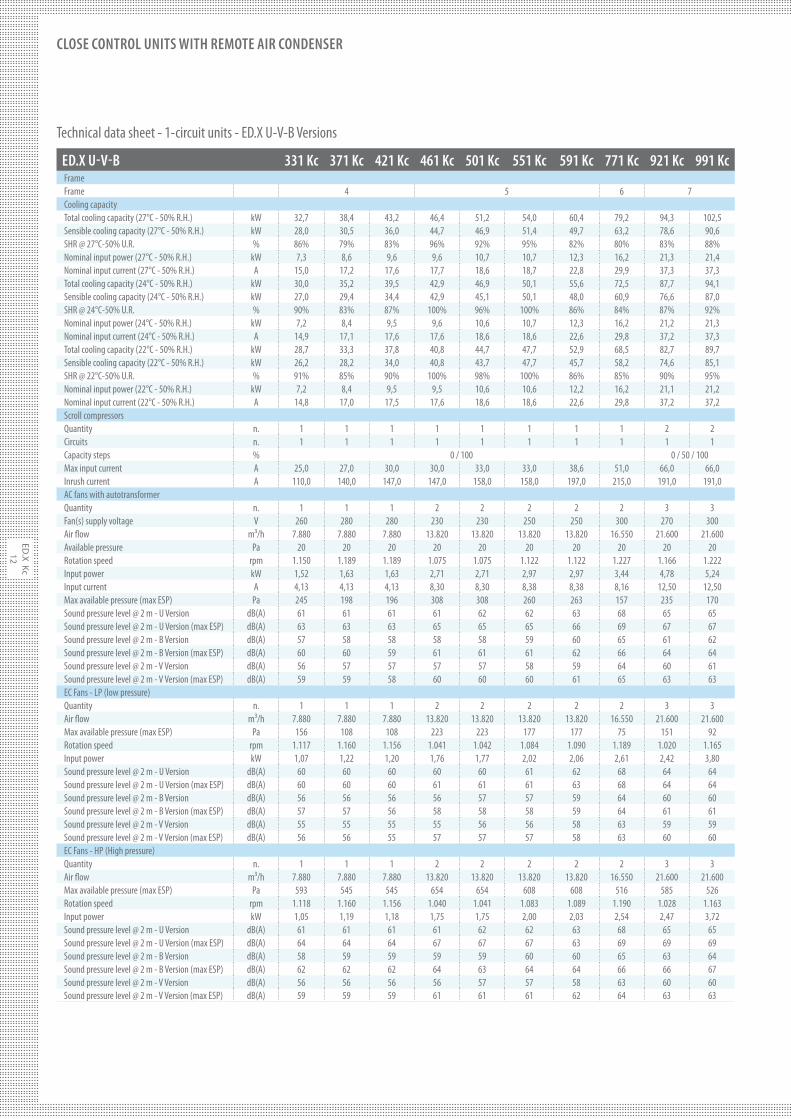
ED.X U-V-B 331 Kc 371 Kc 421 Kc 461 Kc 501 Kc 551 Kc 591 Kc 771 Kc 921 Kc 991 Kc
FrameFrame 4 5 6 7Cooling capacityTotal cooling capacity (27°C - 50% R.H.) kW 32,7 38,4 43,2 46,4 51,2 54,0 60,4 79,2 94,3 102,5Sensible cooling capacity (27°C - 50% R.H.) kW 28,0 30,5 36,0 44,7 46,9 51,4 49,7 63,2 78,6 90,6SHR @ 27°C-50% U.R. % 86% 79% 83% 96% 92% 95% 82% 80% 83% 88%Nominal input power (27°C - 50% R.H.) kW 7,3 8,6 9,6 9,6 10,7 10,7 12,3 16,2 21,3 21,4Nominal input current (27°C - 50% R.H.) A 15,0 17,2 17,6 17,7 18,6 18,7 22,8 29,9 37,3 37,3Total cooling capacity (24°C - 50% R.H.) kW 30,0 35,2 39,5 42,9 46,9 50,1 55,6 72,5 87,7 94,1Sensible cooling capacity (24°C - 50% R.H.) kW 27,0 29,4 34,4 42,9 45,1 50,1 48,0 60,9 76,6 87,0SHR @ 24°C-50% U.R. % 90% 83% 87% 100% 96% 100% 86% 84% 87% 92%Nominal input power (24°C - 50% R.H.) kW 7,2 8,4 9,5 9,6 10,6 10,7 12,3 16,2 21,2 21,3Nominal input current (24°C - 50% R.H.) A 14,9 17,1 17,6 17,6 18,6 18,6 22,6 29,8 37,2 37,3Total cooling capacity (22°C - 50% R.H.) kW 28,7 33,3 37,8 40,8 44,7 47,7 52,9 68,5 82,7 89,7Sensible cooling capacity (22°C - 50% R.H.) kW 26,2 28,2 34,0 40,8 43,7 47,7 45,7 58,2 74,6 85,1SHR @ 22°C-50% U.R. % 91% 85% 90% 100% 98% 100% 86% 85% 90% 95%Nominal input power (22°C - 50% R.H.) kW 7,2 8,4 9,5 9,5 10,6 10,6 12,2 16,2 21,1 21,2Nominal input current (22°C - 50% R.H.) A 14,8 17,0 17,5 17,6 18,6 18,6 22,6 29,8 37,2 37,2Scroll compressorsQuantity n. 1 1 1 1 1 1 1 1 2 2Circuits n. 1 1 1 1 1 1 1 1 1 1Capacity steps % 0 / 100 0 / 50 / 100Max input current A 25,0 27,0 30,0 30,0 33,0 33,0 38,6 51,0 66,0 66,0Inrush current A 110,0 140,0 147,0 147,0 158,0 158,0 197,0 215,0 191,0 191,0AC fans with autotransformerQuantity n. 1 1 1 2 2 2 2 2 3 3Fan(s) supply voltage V 260 280 280 230 230 250 250 300 270 300Air $ow m³/h 7.880 7.880 7.880 13.820 13.820 13.820 13.820 16.550 21.600 21.600Available pressure Pa 20 20 20 20 20 20 20 20 20 20Rotation speed rpm 1.150 1.189 1.189 1.075 1.075 1.122 1.122 1.227 1.166 1.222Input power kW 1,52 1,63 1,63 2,71 2,71 2,97 2,97 3,44 4,78 5,24Input current A 4,13 4,13 4,13 8,30 8,30 8,38 8,38 8,16 12,50 12,50Max available pressure (max ESP) Pa 245 198 196 308 308 260 263 157 235 170Sound pressure level @ 2 m - U Version dB(A) 61 61 61 61 62 62 63 68 65 65Sound pressure level @ 2 m - U Version (max ESP) dB(A) 63 63 63 65 65 65 66 69 67 67Sound pressure level @ 2 m - B Version dB(A) 57 58 58 58 58 59 60 65 61 62Sound pressure level @ 2 m - B Version (max ESP) dB(A) 60 60 59 61 61 61 62 66 64 64Sound pressure level @ 2 m - V Version dB(A) 56 57 57 57 57 58 59 64 60 61Sound pressure level @ 2 m - V Version (max ESP) dB(A) 59 59 58 60 60 60 61 65 63 63EC Fans - LP (low pressure)Quantity n. 1 1 1 2 2 2 2 2 3 3Air $ow m³/h 7.880 7.880 7.880 13.820 13.820 13.820 13.820 16.550 21.600 21.600Max available pressure (max ESP) Pa 156 108 108 223 223 177 177 75 151 92Rotation speed rpm 1.117 1.160 1.156 1.041 1.042 1.084 1.090 1.189 1.020 1.165Input power kW 1,07 1,22 1,20 1,76 1,77 2,02 2,06 2,61 2,42 3,80Sound pressure level @ 2 m - U Version dB(A) 60 60 60 60 60 61 62 68 64 64Sound pressure level @ 2 m - U Version (max ESP) dB(A) 60 60 60 61 61 61 63 68 64 64Sound pressure level @ 2 m - B Version dB(A) 56 56 56 56 57 57 59 64 60 60Sound pressure level @ 2 m - B Version (max ESP) dB(A) 57 57 56 58 58 58 59 64 61 61Sound pressure level @ 2 m - V Version dB(A) 55 55 55 55 56 56 58 63 59 59Sound pressure level @ 2 m - V Version (max ESP) dB(A) 56 56 55 57 57 57 58 63 60 60EC Fans - HP (High pressure)Quantity n. 1 1 1 2 2 2 2 2 3 3Air $ow m³/h 7.880 7.880 7.880 13.820 13.820 13.820 13.820 16.550 21.600 21.600Max available pressure (max ESP) Pa 593 545 545 654 654 608 608 516 585 526Rotation speed rpm 1.118 1.160 1.156 1.040 1.041 1.083 1.089 1.190 1.028 1.163Input power kW 1,05 1,19 1,18 1,75 1,75 2,00 2,03 2,54 2,47 3,72Sound pressure level @ 2 m - U Version dB(A) 61 61 61 61 62 62 63 68 65 65Sound pressure level @ 2 m - U Version (max ESP) dB(A) 64 64 64 67 67 67 63 69 69 69Sound pressure level @ 2 m - B Version dB(A) 58 59 59 59 59 60 60 65 63 64Sound pressure level @ 2 m - B Version (max ESP) dB(A) 62 62 62 64 63 64 64 66 66 67Sound pressure level @ 2 m - V Version dB(A) 56 56 56 56 57 57 58 63 60 60Sound pressure level @ 2 m - V Version (max ESP) dB(A) 59 59 59 61 61 61 62 64 63 63
Technical data sheet - 1-circuit units - ED.X U-V-B Versions
ED
.X
Kc
13
CLOSE CONTROL UNITS WITH REMOTE AIR CONDENSER
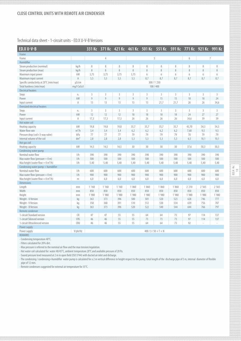
ED.X U-V-B 331 Kc 371 Kc 421 Kc 461 Kc 501 Kc 551 Kc 591 Kc 771 Kc 921 Kc 991 Kc
FrameFrame 4 5 6 7Humidi#erSteam production (nominal) kg/h 8 8 8 8 8 8 8 8 8 8Steam production (max) kg/h 8 8 8 8 8 8 8 8 8 8Maximum input power kW 3,75 3,75 3,75 3,75 6 6 6 6 6 6Maximum input current A 5,5 5,5 5,5 5,5 8,7 8,7 8,7 8,7 8,7 8,7Speci#c conductivity at 20°C (min/max) µS/cm 300 / 1˙250Total hardness (min/max) mg/l CaCo3 100 / 400Electrical heatersSteps n. 3 3 3 3 3 3 3 3 3 3Power kW 9 9 9 9 9 15 15 18 18 24Input current A 13 13 13 13 13 21,7 21,7 26 26 34,6Oversized electrical heatersSteps n. 3 3 3 3 3 3 3 3 3 3Power kW 12 12 12 18 18 18 18 24 27 27Input current A 17,3 17,3 17,3 26 26 26 26 34,6 39 39Hot water coilHeating capacity kW 19,8 19,8 19,8 35,7 35,7 35,7 35,7 43,70 54,3 54,3Water $ow rate m³/h 3,4 3,4 3,4 6,2 6,2 6,2 6,2 7,60 9,5 9,5Pressure drop (coil+3-way valve) kPa 77 77 77 79 79 79 79 70 79 79Internal volume of the coil dm³ 2,8 2,8 2,8 5,3 5,3 5,3 5,3 6,5 10,1 10,1Hot gas coilHeating capacity kW 14,5 14,5 14,5 30 30 30 30 37,6 50,3 50,3Condensing water pump Nominal water $ow l/h 390 390 390 390 390 390 390 390 390 390Max water $ow (pressure = 0 m) l/h 500 500 500 500 500 500 500 500 500 500Max height (water $ow = 0 m³/h) l/h 5,40 5,40 5,40 5,40 5,40 5,40 5,40 5,40 5,40 5,40Condensing water pump + humidi#erNominal water $ow l/h 600 600 600 600 600 600 600 600 600 600Max water $ow (pressure = 0 m) l/h 900 900 900 900 900 900 900 900 900 900Max height (water $ow = 0 m³/h) m 6,0 6,0 6,0 6,0 6,0 6,0 6,0 6,0 6,0 6,0DimensionsLength mm 1˙160 1˙160 1˙160 1˙860 1˙860 1˙860 1˙860 2˙210 2˙565 2˙565Width mm 850 850 850 850 850 850 850 850 850 850Height mm 1˙980 1˙980 1˙980 1˙980 1˙980 1˙980 1˙980 1˙980 1˙980 1˙980Weight - U Version kg 363 373 396 500 501 520 523 628 746 777Weight - V Version kg 358 368 391 510 512 530 534 639 756 787Weight - B Version kg 363 373 396 520 522 540 544 644 766 797Remote condenser1-circuit Standard version CR 47 47 55 55 64 64 73 97 114 1371-circuit Silenced version CRS 46 46 55 55 73 73 73 97 114 1371-circuit Ultrasilenced version CRU 46 46 55 55 64 64 73 92 - -Power supplyPower supply V/ph/Hz 400 / 3 / 50 + T + NREMARKS- Condensing temperature 48°C.- Filters calculated for 20% dirt.- Max pressure is referred to the nominal air $ow and the max tension/regulation.- Hot water coil calculated for: water 40/45°C, ambient temperature 20°C and available pressure of 20 Pa.- Sound pressure level measured at 2 m in open #eld (ISO 3744) with ducted air inlet and dicharge.- The condensing / condensing+humidi#er water pump is calculated for a 2 m vertical di"erence in height respect to the pump; total length of the discharge pipe of 5 m, internal diameter of $exible pipe of 12 mm.- Remote condensers suggested for external air temperature for 35°C.
Technical data sheet - 1-circuit units - ED.X U-V-B Versions
ED
.X K
c
14
CLOSE CONTROL UNITS WITH REMOTE AIR CONDENSER
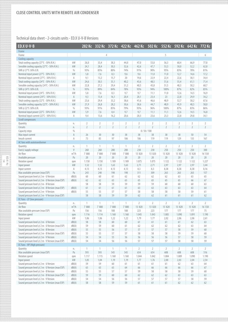
ED.X U-V-B 282 Kc 332 Kc 372 Kc 422 Kc 462 Kc 502 Kc 552 Kc 592 Kc 642 Kc 772 Kc
FrameFrame 4 5 6Cooling capacityTotal cooling capacity (27°C - 50% R.H.) kW 26,0 33,4 38,3 44,0 47,0 53,0 56,3 60,4 66,9 77,8Sensible cooling capacity (27°C - 50% R.H.) kW 24,1 28,4 30,5 32,6 42,6 47,7 53,3 50,0 52,2 62,8SHR @ 27°C-50% U.R. % 93% 85% 80% 74% 91% 90% 95% 83% 78% 81%Nominal input power (27°C - 50% R.H.) kW 5,8 7,6 8,3 9,6 9,6 11,0 11,0 12,7 14,6 17,2Nominal input current (27°C - 50% R.H.) A 9,1 13,2 15,7 20 19,6 22,9 22,4 22,6 30,1 34,4Total cooling capacity (24°C - 50% R.H.) kW 24,6 30,5 35,1 40,2 43,6 48,5 51,6 55,4 61,1 71,4Sensible cooling capacity (24°C - 50% R.H.) kW 22,8 27,2 29,4 31,2 40,5 45,8 51,5 48,3 50,2 60,7SHR @ 24°C-50% U.R. % 93% 89% 84% 78% 93% 94% 100% 87% 82% 85%Nominal input power (24°C - 50% R.H.) kW 5,8 7,6 8,3 9,7 9,7 11,1 11,0 12,6 14,5 16,9Nominal input current (24°C - 50% R.H.) A 9,3 13,4 16,1 20,4 20,1 23,4 23 22,8 29,9 34,2Total cooling capacity (22°C - 50% R.H.) kW 23,6 29,4 33,2 38,6 41,6 46,6 48,9 52,7 58,2 67,6Sensible cooling capacity (22°C - 50% R.H.) kW 21,9 26,8 28,2 30,6 38,6 44,7 48,9 45,9 48,5 58,0SHR @ 22°C-50% U.R. % 93% 91% 85% 79% 93% 96% 100% 87% 83% 86%Nominal input power (22°C - 50% R.H.) kW 5,9 7,6 8,4 9,7 9,7 11,1 11,1 12,6 14,5 16,8Nominal input current (22°C - 50% R.H.) A 9,4 13,6 16,2 20,6 20,3 23,6 23,3 22,8 29,8 34,1Scroll compressorsQuantity n. 2 2 2 2 2 2 2 2 2 2Circuits n. 2 2 2 2 2 2 2 2 2 2Capacity steps % 0 / 50 / 100Max input current A 26 30 30 38 38 38 38 38 50 54Inrush current A 73 85 97 106 106 119 119 129 135 167AC fans with autotransformerQuantity n. 1 1 1 1 2 2 2 2 2 2Fan(s) supply voltage V 260 260 280 280 230 230 250 250 250 300Air $ow m³/h 7˙880 7˙880 7˙880 7˙880 13˙820 13˙820 13˙820 13˙820 13˙820 16˙550Available pressure Pa 20 20 20 20 20 20 20 20 20 20Rotation speed rpm 1.150 1.150 1.189 1.189 1.075 1.075 1.122 1.122 1.122 1.227Input power kW 1,52 1,52 1,63 1,63 2,71 2,71 2,97 2,97 2,97 3,44Input current A 4,13 4,13 4,13 4,13 8,3 8,3 8,38 8,38 8,38 8,16Max available pressure (max ESP) Pa 243 240 198 198 311 309 263 263 263 157Sound pressure level @ 2 m - U Version dB(A) 60 60 61 62 62 62 62 63 63 65Sound pressure level @ 2 m - U Version (max ESP) dB(A) 62 62 63 63 65 65 65 65 66 67Sound pressure level @ 2 m - B Version 58 58 59 59 59 59 60 60 60 63Sound pressure level @ 2 m - B Version (max ESP) dB(A) 61 61 61 61 63 63 63 63 63 64Sound pressure level @ 2 m - V Version dB(A) 55 55 57 57 58 58 58 58 59 61Sound pressure level @ 2 m - V Version (max ESP) 58 58 59 59 62 62 61 61 61 62EC Fans - LP (low pressure)Quantity n. 1 1 1 1 2 2 2 2 2 2Air $ow m³/h 7˙880 7˙880 7˙880 7˙880 13˙820 13˙820 13˙820 13˙820 13˙820 16˙550Max available pressure (max ESP) Pa 156 156 108 108 223 223 177 177 177 75Rotation speed rpm 1.116 1.114 1.160 1.160 1.045 1.043 1.085 1.090 1.091 1.190Input power kW 1,06 1,06 1,22 1,22 1,79 1,77 2,02 2,06 2,06 2,61Sound pressure level @ 2 m - U Version dB(A) 58 58 60 60 61 61 61 61 62 63Sound pressure level @ 2 m - U Version (max ESP) dB(A) 59 59 60 61 62 62 62 62 63 64Sound pressure level @ 2 m - B Version dB(A) 55 55 56 57 57 57 57 58 59 60Sound pressure level @ 2 m - B Version (max ESP) dB(A) 55 55 57 57 58 58 58 59 59 60Sound pressure level @ 2 m - V Version dB(A) 54 54 55 56 56 56 56 57 58 59Sound pressure level @ 2 m - V Version (max ESP) dB(A) 54 54 56 56 57 57 57 58 58 59EC Fans - HP (High pressure)Quantity n. 1 1 1 1 2 2 2 2 2 2Max available pressure (max ESP) Pa 593 593 545 545 654 654 608 608 608 516Rotation speed rpm 1.117 1.115 1.160 1.160 1.044 1.042 1.084 1.089 1.090 1.190Input power kW 1,05 1,04 1,19 1,19 1,77 1,76 2,00 2,03 2,04 2,54Sound pressure level @ 2 m - U Version dB(A) 59 59 60 61 61 61 61 62 63 64Sound pressure level @ 2 m - U Version (max ESP) dB(A) 63 63 63 64 66 66 66 66 66 67Sound pressure level @ 2 m - B Version dB(A) 55 55 57 57 59 58 58 58 59 60Sound pressure level @ 2 m - B Version (max ESP) dB(A) 59 59 60 60 62 62 62 63 63 63Sound pressure level @ 2 m - V Version dB(A) 54 54 56 56 57 57 57 57 58 59Sound pressure level @ 2 m - V Version (max ESP) dB(A) 58 58 59 59 61 61 61 62 62 62
Technical data sheet - 2-circuits units - ED.X U-V-B Versions
ED
.X
Kc
15
CLOSE CONTROL UNITS WITH REMOTE AIR CONDENSER
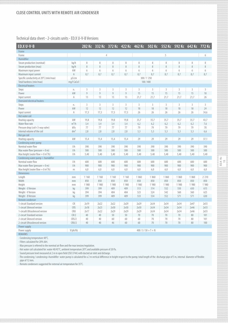
ED.X U-V-B 282 Kc 332 Kc 372 Kc 422 Kc 462 Kc 502 Kc 552 Kc 592 Kc 642 Kc 772 Kc
FrameFrame 4 5 6Humidi#erSteam production (nominal) kg/h 8 8 8 8 8 8 8 8 8 8Steam production (max) kg/h 8 8 8 8 8 8 8 8 8 8Maximum input power kW 6 6 6 6 6 6 6 6 6 6Maximum input current A 8,7 8,7 8,7 8,7 8,7 8,7 8,7 8,7 8,7 8,7Speci#c conductivity at 20°C (min/max) µS/cm 300 / 1˙250Total hardness (min/max) mg/l CaCo3 100 / 400Electrical heatersSteps n. 3 3 3 3 3 3 3 3 3 3Power kW 9 9 9 9 15 15 15 15 15 18Input current A 13 13 13 13 21,7 21,7 21,7 21,7 21,7 26Oversized electrical heatersSteps n. 3 3 3 3 3 3 3 3 3 3Power kW 12 12 12 12 18 18 18 18 18 24Input current A 17,3 17,3 17,3 17,3 26 26 26 26 26 34,6Hot water coilHeating capacity kW 19,8 19,8 19,8 19,8 35,7 35,7 35,7 35,7 35,7 43,7Water $ow rate m³/h 3,4 3,4 3,4 3,4 6,2 6,2 6,2 6,2 6,2 7,6Pressure drop (coil+3-way valve) kPa 77 77 77 77 79 79 79 79 79 70Internal volume of the coil dm³ 2,8 2,8 2,8 2,8 5,3 5,3 5,3 5,3 5,3 6,6Hot gas coilHeating capacity kW 15,4 15,4 15,4 15,4 29 29 29 29 29 37,1Condensing water pump Nominal water $ow l/h 390 390 390 390 390 390 390 390 390 390Max water $ow (pressure = 0 m) l/h 500 500 500 500 500 500 500 500 500 500Max height (water $ow = 0 m³/h) l/h 5,40 5,40 5,40 5,40 5,40 5,40 5,40 5,40 5,40 5,40Condensing water pump + humidi#erNominal water $ow l/h 600 600 600 600 600 600 600 600 600 600Max water $ow (pressure = 0 m) l/h 900 900 900 900 900 900 900 900 900 900Max height (water $ow = 0 m³/h) m 6,0 6,0 6,0 6,0 6,0 6,0 6,0 6,0 6,0 6,0DimensionsLength mm 1˙160 1˙160 1˙160 1˙160 1˙860 1˙860 1˙860 1˙860 1˙860 2˙210Width mm 850 850 850 850 850 850 850 850 850 850Height mm 1˙980 1˙980 1˙980 1˙980 1˙980 1˙980 1˙980 1˙980 1˙980 1˙980Weight - U Version kg 399 399 409 409 513 514 532 550 650 615Weight - V Version kg 394 394 404 404 523 524 542 560 560 625Weight - B Version kg 399 399 409 409 533 534 552 571 571 630Remote condenser1-circuit Standard version CR 2x19 2x22 2x22 2x29 2x29 2x34 2x34 2x34 2x47 2x551-circuit Silenced version CRS 2x18 2x23 2x30 2x30 2x30 2x34 2x34 2x34 2x46 2x551-circuilt Ultrasilenced version CRU 2x17 2x22 2x29 2x29 2x29 2x34 2x34 2x34 2x46 2x552-circuit Standard version CR/2 40 40 50 50 70 70 70 70 80 1012-circuit Silenced version CRS/2 40 40 60 60 60 70 70 70 80 1012-circuit Ultrasilenced version CRU/2 40 40 46 60 60 70 70 70 80 100Power supplyPower supply V/ph/Hz 400 / 3 / 50 + T + NREMARKS- Condensing temperature 48°C.- Filters calculated for 20% dirt.- Max pressure is referred to the nominal air $ow and the max tension/regulation.- Hot water coil calculated for: water 40/45°C, ambient temperature 20°C and available pressure of 20 Pa.- Sound pressure level measured at 2 m in open #eld (ISO 3744) with ducted air inlet and dicharge.- The condensing / condensing+humidi#er water pump is calculated for a 2 m vertical di"erence in height respect to the pump; total length of the discharge pipe of 5 m, internal diameter of $exible pipe of 12 mm.- Remote condensers suggested for external air temperature for 35°C.
Technical data sheet - 2-circuits units - ED.X U-V-B Versions
ED
.X K
c
16
CLOSE CONTROL UNITS WITH REMOTE AIR CONDENSER
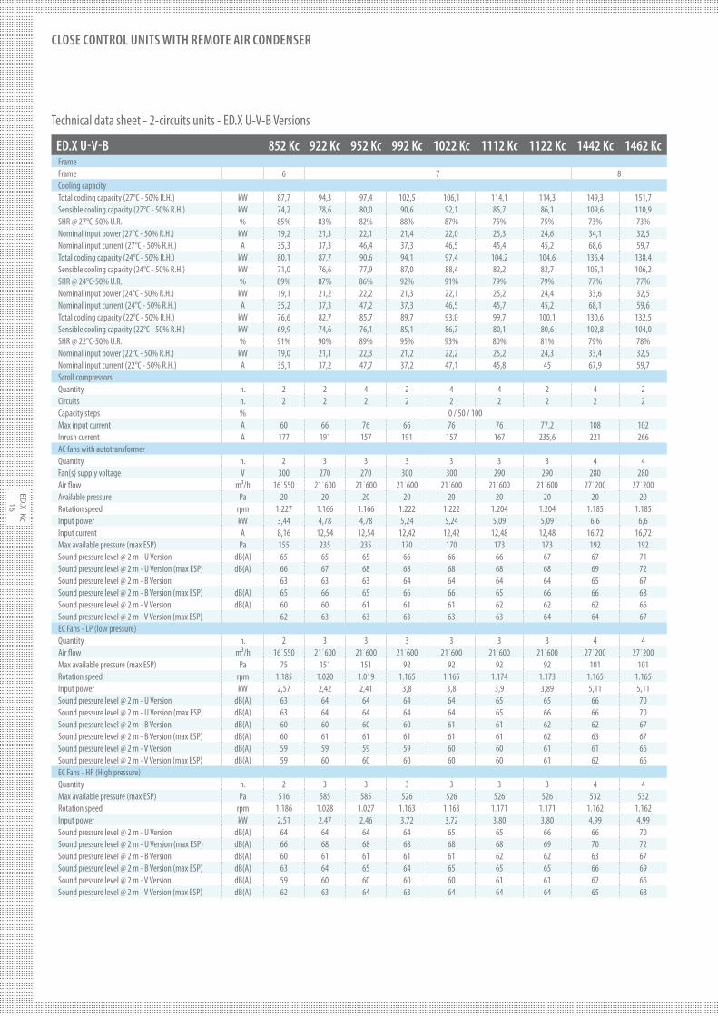
ED.X U-V-B 852 Kc 922 Kc 952 Kc 992 Kc 1022 Kc 1112 Kc 1122 Kc 1442 Kc 1462 Kc
FrameFrame 6 7 8Cooling capacityTotal cooling capacity (27°C - 50% R.H.) kW 87,7 94,3 97,4 102,5 106,1 114,1 114,3 149,3 151,7Sensible cooling capacity (27°C - 50% R.H.) kW 74,2 78,6 80,0 90,6 92,1 85,7 86,1 109,6 110,9SHR @ 27°C-50% U.R. % 85% 83% 82% 88% 87% 75% 75% 73% 73%Nominal input power (27°C - 50% R.H.) kW 19,2 21,3 22,1 21,4 22,0 25,3 24,6 34,1 32,5Nominal input current (27°C - 50% R.H.) A 35,3 37,3 46,4 37,3 46,5 45,4 45,2 68,6 59,7Total cooling capacity (24°C - 50% R.H.) kW 80,1 87,7 90,6 94,1 97,4 104,2 104,6 136,4 138,4Sensible cooling capacity (24°C - 50% R.H.) kW 71,0 76,6 77,9 87,0 88,4 82,2 82,7 105,1 106,2SHR @ 24°C-50% U.R. % 89% 87% 86% 92% 91% 79% 79% 77% 77%Nominal input power (24°C - 50% R.H.) kW 19,1 21,2 22,2 21,3 22,1 25,2 24,4 33,6 32,5Nominal input current (24°C - 50% R.H.) A 35,2 37,3 47,2 37,3 46,5 45,7 45,2 68,1 59,6Total cooling capacity (22°C - 50% R.H.) kW 76,6 82,7 85,7 89,7 93,0 99,7 100,1 130,6 132,5Sensible cooling capacity (22°C - 50% R.H.) kW 69,9 74,6 76,1 85,1 86,7 80,1 80,6 102,8 104,0SHR @ 22°C-50% U.R. % 91% 90% 89% 95% 93% 80% 81% 79% 78%Nominal input power (22°C - 50% R.H.) kW 19,0 21,1 22,3 21,2 22,2 25,2 24,3 33,4 32,5Nominal input current (22°C - 50% R.H.) A 35,1 37,2 47,7 37,2 47,1 45,8 45 67,9 59,7Scroll compressorsQuantity n. 2 2 4 2 4 4 2 4 2Circuits n. 2 2 2 2 2 2 2 2 2Capacity steps % 0 / 50 / 100Max input current A 60 66 76 66 76 76 77,2 108 102Inrush current A 177 191 157 191 157 167 235,6 221 266AC fans with autotransformerQuantity n. 2 3 3 3 3 3 3 4 4Fan(s) supply voltage V 300 270 270 300 300 290 290 280 280Air $ow m³/h 16˙550 21˙600 21˙600 21˙600 21˙600 21˙600 21˙600 27˙200 27˙200Available pressure Pa 20 20 20 20 20 20 20 20 20Rotation speed rpm 1.227 1.166 1.166 1.222 1.222 1.204 1.204 1.185 1.185Input power kW 3,44 4,78 4,78 5,24 5,24 5,09 5,09 6,6 6,6Input current A 8,16 12,54 12,54 12,42 12,42 12,48 12,48 16,72 16,72Max available pressure (max ESP) Pa 155 235 235 170 170 173 173 192 192Sound pressure level @ 2 m - U Version dB(A) 65 65 65 66 66 66 67 67 71Sound pressure level @ 2 m - U Version (max ESP) dB(A) 66 67 68 68 68 68 68 69 72Sound pressure level @ 2 m - B Version 63 63 63 64 64 64 64 65 67Sound pressure level @ 2 m - B Version (max ESP) dB(A) 65 66 65 66 66 65 66 66 68Sound pressure level @ 2 m - V Version dB(A) 60 60 61 61 61 62 62 62 66Sound pressure level @ 2 m - V Version (max ESP) 62 63 63 63 63 63 64 64 67EC Fans - LP (low pressure)Quantity n. 2 3 3 3 3 3 3 4 4Air $ow m³/h 16˙550 21˙600 21˙600 21˙600 21˙600 21˙600 21˙600 27˙200 27˙200Max available pressure (max ESP) Pa 75 151 151 92 92 92 92 101 101Rotation speed rpm 1.185 1.020 1.019 1.165 1.165 1.174 1.173 1.165 1.165Input power kW 2,57 2,42 2,41 3,8 3,8 3,9 3,89 5,11 5,11Sound pressure level @ 2 m - U Version dB(A) 63 64 64 64 64 65 65 66 70Sound pressure level @ 2 m - U Version (max ESP) dB(A) 63 64 64 64 64 65 66 66 70Sound pressure level @ 2 m - B Version dB(A) 60 60 60 60 61 61 62 62 67Sound pressure level @ 2 m - B Version (max ESP) dB(A) 60 61 61 61 61 61 62 63 67Sound pressure level @ 2 m - V Version dB(A) 59 59 59 59 60 60 61 61 66Sound pressure level @ 2 m - V Version (max ESP) dB(A) 59 60 60 60 60 60 61 62 66EC Fans - HP (High pressure)Quantity n. 2 3 3 3 3 3 3 4 4Max available pressure (max ESP) Pa 516 585 585 526 526 526 526 532 532Rotation speed rpm 1.186 1.028 1.027 1.163 1.163 1.171 1.171 1.162 1.162Input power kW 2,51 2,47 2,46 3,72 3,72 3,80 3,80 4,99 4,99Sound pressure level @ 2 m - U Version dB(A) 64 64 64 64 65 65 66 66 70Sound pressure level @ 2 m - U Version (max ESP) dB(A) 66 68 68 68 68 68 69 70 72Sound pressure level @ 2 m - B Version dB(A) 60 61 61 61 61 62 62 63 67Sound pressure level @ 2 m - B Version (max ESP) dB(A) 63 64 65 64 65 65 65 66 69Sound pressure level @ 2 m - V Version dB(A) 59 60 60 60 60 61 61 62 66Sound pressure level @ 2 m - V Version (max ESP) dB(A) 62 63 64 63 64 64 64 65 68
Technical data sheet - 2-circuits units - ED.X U-V-B Versions
ED
.X
Kc
17
CLOSE CONTROL UNITS WITH REMOTE AIR CONDENSER
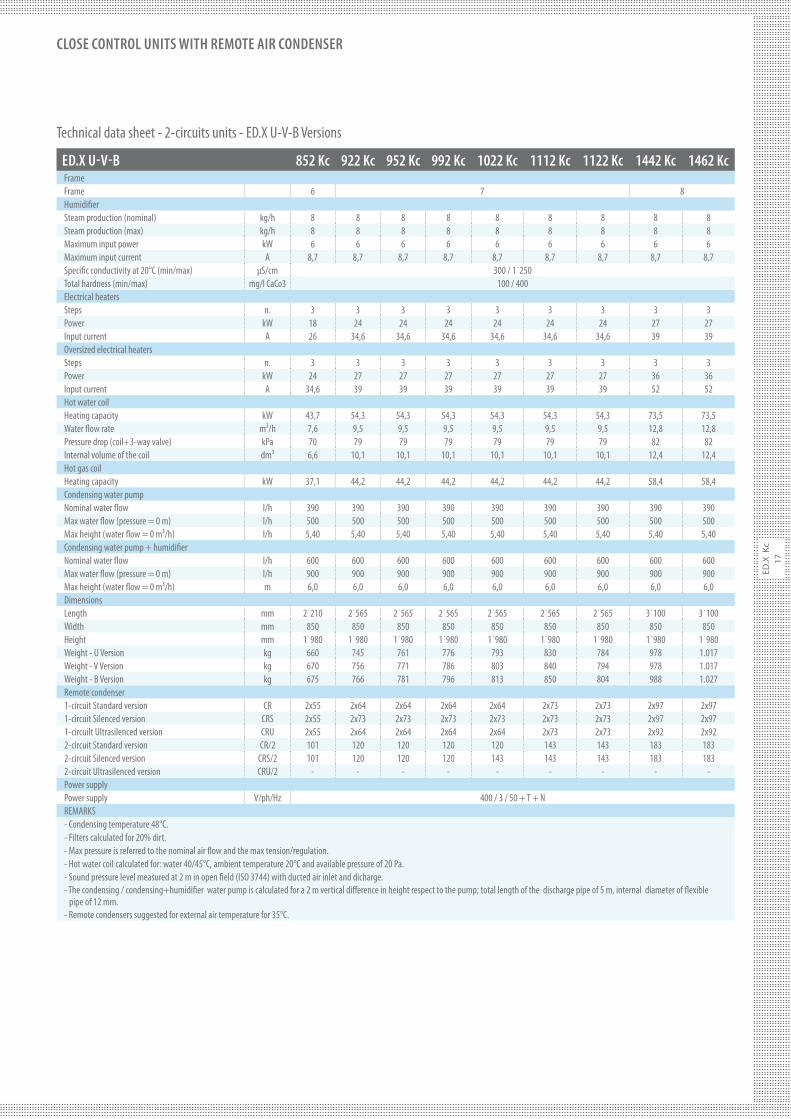
ED.X U-V-B 852 Kc 922 Kc 952 Kc 992 Kc 1022 Kc 1112 Kc 1122 Kc 1442 Kc 1462 Kc
FrameFrame 6 7 8Humidi#erSteam production (nominal) kg/h 8 8 8 8 8 8 8 8 8Steam production (max) kg/h 8 8 8 8 8 8 8 8 8Maximum input power kW 6 6 6 6 6 6 6 6 6Maximum input current A 8,7 8,7 8,7 8,7 8,7 8,7 8,7 8,7 8,7Speci#c conductivity at 20°C (min/max) µS/cm 300 / 1˙250Total hardness (min/max) mg/l CaCo3 100 / 400Electrical heatersSteps n. 3 3 3 3 3 3 3 3 3Power kW 18 24 24 24 24 24 24 27 27Input current A 26 34,6 34,6 34,6 34,6 34,6 34,6 39 39Oversized electrical heatersSteps n. 3 3 3 3 3 3 3 3 3Power kW 24 27 27 27 27 27 27 36 36Input current A 34,6 39 39 39 39 39 39 52 52Hot water coilHeating capacity kW 43,7 54,3 54,3 54,3 54,3 54,3 54,3 73,5 73,5Water $ow rate m³/h 7,6 9,5 9,5 9,5 9,5 9,5 9,5 12,8 12,8Pressure drop (coil+3-way valve) kPa 70 79 79 79 79 79 79 82 82Internal volume of the coil dm³ 6,6 10,1 10,1 10,1 10,1 10,1 10,1 12,4 12,4Hot gas coilHeating capacity kW 37,1 44,2 44,2 44,2 44,2 44,2 44,2 58,4 58,4Condensing water pump Nominal water $ow l/h 390 390 390 390 390 390 390 390 390Max water $ow (pressure = 0 m) l/h 500 500 500 500 500 500 500 500 500Max height (water $ow = 0 m³/h) l/h 5,40 5,40 5,40 5,40 5,40 5,40 5,40 5,40 5,40Condensing water pump + humidi#erNominal water $ow l/h 600 600 600 600 600 600 600 600 600Max water $ow (pressure = 0 m) l/h 900 900 900 900 900 900 900 900 900Max height (water $ow = 0 m³/h) m 6,0 6,0 6,0 6,0 6,0 6,0 6,0 6,0 6,0DimensionsLength mm 2˙210 2˙565 2˙565 2˙565 2˙565 2˙565 2˙565 3˙100 3˙100Width mm 850 850 850 850 850 850 850 850 850Height mm 1˙980 1˙980 1˙980 1˙980 1˙980 1˙980 1˙980 1˙980 1˙980Weight - U Version kg 660 745 761 776 793 830 784 978 1.017Weight - V Version kg 670 756 771 786 803 840 794 978 1.017Weight - B Version kg 675 766 781 796 813 850 804 988 1.027Remote condenser1-circuit Standard version CR 2x55 2x64 2x64 2x64 2x64 2x73 2x73 2x97 2x971-circuit Silenced version CRS 2x55 2x73 2x73 2x73 2x73 2x73 2x73 2x97 2x971-circuilt Ultrasilenced version CRU 2x55 2x64 2x64 2x64 2x64 2x73 2x73 2x92 2x922-circuit Standard version CR/2 101 120 120 120 120 143 143 183 1832-circuit Silenced version CRS/2 101 120 120 120 143 143 143 183 1832-circuit Ultrasilenced version CRU/2 - - - - - - - - -Power supplyPower supply V/ph/Hz 400 / 3 / 50 + T + NREMARKS- Condensing temperature 48°C.- Filters calculated for 20% dirt.- Max pressure is referred to the nominal air $ow and the max tension/regulation.- Hot water coil calculated for: water 40/45°C, ambient temperature 20°C and available pressure of 20 Pa.- Sound pressure level measured at 2 m in open #eld (ISO 3744) with ducted air inlet and dicharge.- The condensing / condensing+humidi#er water pump is calculated for a 2 m vertical di"erence in height respect to the pump; total length of the discharge pipe of 5 m, internal diameter of $exible pipe of 12 mm.- Remote condensers suggested for external air temperature for 35°C.
Technical data sheet - 2-circuits units - ED.X U-V-B Versions
ED
.X K
c
18
CLOSE CONTROL UNITS WITH REMOTE AIR CONDENSER
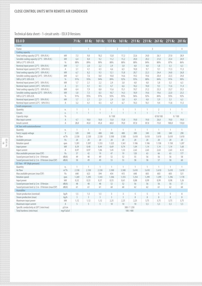
ED.X D 71 Kc 81 Kc 101 Kc 131 Kc 161 Kc 211 Kc 231 Kc 261 Kc 271 Kc 281 Kc
FrameFrame 1 2 3 4Cooling capacityTotal cooling capacity (27°C - 50% R.H.) kW 7,3 9,0 10,2 12,8 17,2 22,6 24,0 26,1 27,0 28,9Sensible cooling capacity (27°C - 50% R.H.) kW 6,4 8,0 9,2 11,2 15,2 20,0 20,2 21,0 23,4 24,9SHR @ 27°C-50% U.R. % 88% 89% 90% 88% 88% 88% 84% 80% 87% 86%Nominal input power (27°C - 50% R.H.) kW 1,7 2,0 2,2 2,9 3,8 4,8 4,8 5,8 5,5 6,3Nominal input current (27°C - 50% R.H.) A 3,1 4,1 4,5 4,6 6,5 10,0 9,7 9,1 11,3 11,3Total cooling capacity (24°C - 50% R.H.) kW 6,7 8,2 9,3 12,1 15,8 20,7 22,3 24,4 24,8 26,8Sensible cooling capacity (24°C - 50% R.H.) kW 6,1 7,6 8,8 10,8 14,6 19,3 19,6 20,4 22,5 24,0SHR @ 24°C-50% U.R. % 91% 93% 94% 89% 92% 93% 88% 84% 91% 90%Nominal input power (24°C - 50% R.H.) kW 1,7 2,1 2,2 2,9 3,8 4,8 4,8 5,8 5,5 6,3Nominal input current (24°C - 50% R.H.) A 3,1 4,1 4,5 4,7 6,6 10,2 10,0 9,3 11,6 11,4Total cooling capacity (22°C - 50% R.H.) kW 6,4 7,9 8,8 11,6 15,1 19,7 21,2 23,3 23,7 25,5Sensible cooling capacity (22°C - 50% R.H.) kW 5,8 7,5 8,5 10,7 14,3 18,9 19,6 19,6 22,0 23,5SHR @ 22°C-50% U.R. % 91% 95% 97% 92% 95% 96% 92% 84% 93% 92%Nominal input power (22°C - 50% R.H.) kW 1,7 2,1 2,3 2,9 3,8 4,9 4,8 5,9 5,5 6,3Nominal input current (22°C - 50% R.H.) A 3,2 4,1 4,5 4,7 6,7 10,3 10,1 9,4 11,8 11,5Scroll compressorsQuantity n. 1 1 1 1 1 1 1 2 1 1Circuits n. 1 1 1 1 1 1 1 1 1 1Capacity steps % 0 / 100 0/50/100 0 / 100Max input current A 4,7 10,0 10,0 13,0 15,0 19,0 19,0 26,0 19,0 19,0Inrush current A 28,0 45,0 45,0 60,0 70,0 87,0 87,0 73,0 100,0 110,0AC fans with autotransformerQuantity n. 1 1 1 1 1 1 1 1 1 1Fan(s) supply voltage V 320 340 400 340 400 300 340 340 340 290Air $ow m³/h 2.330 2.330 2.330 3.500 3.500 5.610 5.610 5.610 5.610 5.610Available pressure Pa 20 20 20 20 20 20 20 20 20 20Rotation speed rpm 1.281 1.307 1.353 1.325 1.361 1.106 1.106 1.158 1.158 1.207Input power kW 0,39 0,40 0,44 0,69 0,74 1,04 1,14 1,14 1,14 1,68Input current A 0,97 0,97 1,06 1,45 1,53 2,63 2,63 2,63 2,63 4,12Max available pressure (max ESP) Pa 57 42 19 47 19 120 63 66 63 177Sound pressure level @ 2 m - D Version dB(A) 49 48 49 52 52 55 56 56 56 58Sound pressure level @ 2 m - D Version (max ESP) dB(A) 50 49 49 53 53 58 58 57 58 60EC Fans - HP (High pressure)Quantity n. 1 1 1 1 1 1 1 1 1 1Air $ow m³/h 2.330 2.330 2.330 3.500 3.500 5.610 5.610 5.610 5.610 5.610Max available pressure (max ESP) Pa 640 623 594 454 415 648 603 603 603 521Rotation speed rpm 1.269 1.295 1.343 1.306 1.355 1.254 1.299 1.299 1.296 1.178Input power kW 0,32 0,33 0,37 0,55 0,61 0,88 0,99 0,99 0,98 1,26Sound pressure level @ 2 m - D Version dB(A) 48 48 48 52 52 56 56 56 56 57Sound pressure level @ 2 m - D Version (max ESP) dB(A) 61 61 61 60 60 62 62 61 62 60Humidi#erSteam production (nominal) kg/h 1,5 1,5 1,5 3 3 5 5 5 5 8Steam production (max) kg/h 3 3 3 3 3 8 8 8 8 8Maximum input power kW 1,12 1,12 1,12 2,25 2,25 2,25 3,75 3,75 3,75 3,75Maximum input current A 5 5 5 10 10 10 5,5 5,5 5,5 5,5Speci#c conductivity at 20°C (min/max) µS/cm 300 / 1˙250Total hardness (min/max) mg/l CaCo3 100 / 400
Technical data sheet - 1-circuit units - ED.X D Versions
ED
.X
Kc
19
CLOSE CONTROL UNITS WITH REMOTE AIR CONDENSER
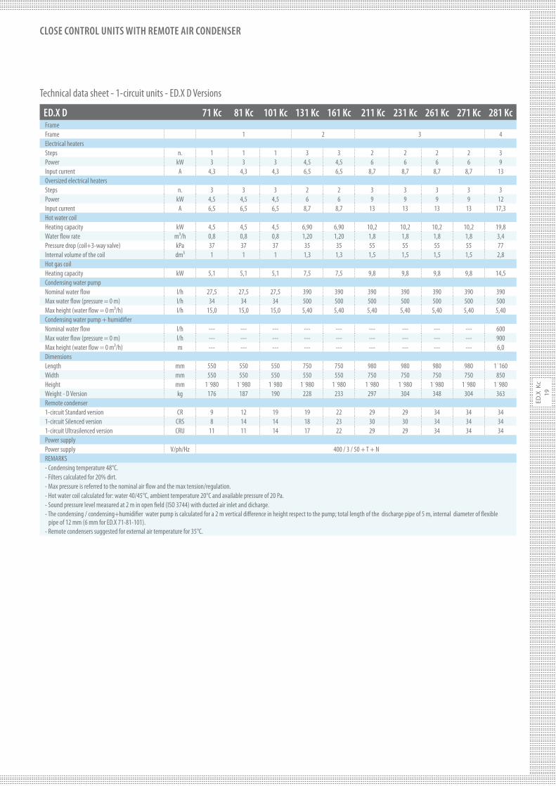
ED.X D 71 Kc 81 Kc 101 Kc 131 Kc 161 Kc 211 Kc 231 Kc 261 Kc 271 Kc 281 Kc
FrameFrame 1 2 3 4Electrical heatersSteps n. 1 1 1 3 3 2 2 2 2 3Power kW 3 3 3 4,5 4,5 6 6 6 6 9Input current A 4,3 4,3 4,3 6,5 6,5 8,7 8,7 8,7 8,7 13Oversized electrical heatersSteps n. 3 3 3 2 2 3 3 3 3 3Power kW 4,5 4,5 4,5 6 6 9 9 9 9 12Input current A 6,5 6,5 6,5 8,7 8,7 13 13 13 13 17,3Hot water coilHeating capacity kW 4,5 4,5 4,5 6,90 6,90 10,2 10,2 10,2 10,2 19,8Water $ow rate m³/h 0,8 0,8 0,8 1,20 1,20 1,8 1,8 1,8 1,8 3,4Pressure drop (coil+3-way valve) kPa 37 37 37 35 35 55 55 55 55 77Internal volume of the coil dm³ 1 1 1 1,3 1,3 1,5 1,5 1,5 1,5 2,8Hot gas coilHeating capacity kW 5,1 5,1 5,1 7,5 7,5 9,8 9,8 9,8 9,8 14,5Condensing water pump Nominal water $ow l/h 27,5 27,5 27,5 390 390 390 390 390 390 390Max water $ow (pressure = 0 m) l/h 34 34 34 500 500 500 500 500 500 500Max height (water $ow = 0 m³/h) l/h 15,0 15,0 15,0 5,40 5,40 5,40 5,40 5,40 5,40 5,40Condensing water pump + humidi#erNominal water $ow l/h --- --- --- --- --- --- --- --- --- 600Max water $ow (pressure = 0 m) l/h --- --- --- --- --- --- --- --- --- 900Max height (water $ow = 0 m³/h) m --- --- --- --- --- --- --- --- --- 6,0DimensionsLength mm 550 550 550 750 750 980 980 980 980 1˙160Width mm 550 550 550 550 550 750 750 750 750 850Height mm 1˙980 1˙980 1˙980 1˙980 1˙980 1˙980 1˙980 1˙980 1˙980 1˙980Weight - D Version kg 176 187 190 228 233 297 304 348 304 363Remote condenser1-circuit Standard version CR 9 12 19 19 22 29 29 34 34 341-circuit Silenced version CRS 8 14 14 18 23 30 30 34 34 341-circuit Ultrasilenced version CRU 11 11 14 17 22 29 29 34 34 34Power supplyPower supply V/ph/Hz 400 / 3 / 50 + T + NREMARKS- Condensing temperature 48°C.- Filters calculated for 20% dirt.- Max pressure is referred to the nominal air $ow and the max tension/regulation.- Hot water coil calculated for: water 40/45°C, ambient temperature 20°C and available pressure of 20 Pa.- Sound pressure level measured at 2 m in open #eld (ISO 3744) with ducted air inlet and dicharge.- The condensing / condensing+humidi#er water pump is calculated for a 2 m vertical di"erence in height respect to the pump; total length of the discharge pipe of 5 m, internal diameter of $exible pipe of 12 mm (6 mm for ED.X 71-81-101).- Remote condensers suggested for external air temperature for 35°C.
Technical data sheet - 1-circuit units - ED.X D Versions
ED
.X K
c
20
CLOSE CONTROL UNITS WITH REMOTE AIR CONDENSER
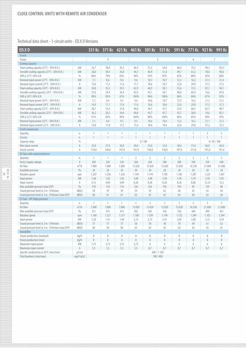
ED.X D 331 Kc 371 Kc 421 Kc 461 Kc 501 Kc 551 Kc 591 Kc 771 Kc 921 Kc 991 Kc
FrameFrame 4 5 6 7Cooling capacityTotal cooling capacity (27°C - 50% R.H.) kW 32,7 38,4 43,2 46,4 51,2 54,0 60,4 79,2 94,3 102,5Sensible cooling capacity (27°C - 50% R.H.) kW 28,0 30,5 36,0 44,7 46,9 51,4 49,7 63,2 78,6 90,6SHR @ 27°C-50% U.R. % 86% 79% 83% 96% 92% 95% 82% 80% 83% 88%Nominal input power (27°C - 50% R.H.) kW 7,3 8,6 9,6 9,6 10,7 10,7 12,3 16,2 21,3 21,4Nominal input current (27°C - 50% R.H.) A 15,0 17,2 17,6 17,7 18,6 18,7 22,8 29,9 37,3 37,3Total cooling capacity (24°C - 50% R.H.) kW 30,0 35,2 39,5 42,9 46,9 50,1 55,6 72,5 87,7 94,1Sensible cooling capacity (24°C - 50% R.H.) kW 27,0 29,4 34,4 42,9 45,1 50,1 48,0 60,9 76,6 87,0SHR @ 24°C-50% U.R. % 90% 83% 87% 100% 96% 100% 86% 84% 87% 92%Nominal input power (24°C - 50% R.H.) kW 7,2 8,4 9,5 9,6 10,6 10,7 12,3 16,2 21,2 21,3Nominal input current (24°C - 50% R.H.) A 14,9 17,1 17,6 17,6 18,6 18,6 22,6 29,8 37,2 37,3Total cooling capacity (22°C - 50% R.H.) kW 28,7 33,3 37,8 40,8 44,7 47,7 52,9 68,5 82,7 89,7Sensible cooling capacity (22°C - 50% R.H.) kW 26,2 28,2 34,0 40,8 43,7 47,7 45,7 58,0 74,6 85,1SHR @ 22°C-50% U.R. % 91% 85% 90% 100% 98% 100% 86% 85% 90% 95%Nominal input power (22°C - 50% R.H.) kW 7,2 8,4 9,5 9,5 10,6 10,6 12,2 16,2 21,1 21,2Nominal input current (22°C - 50% R.H.) A 14,8 17,0 17,5 17,6 18,6 18,6 22,6 29,8 37,2 37,2Scroll compressorsQuantity n. 1 1 1 1 1 1 1 1 2 2Circuits n. 1 1 1 1 1 1 1 1 1 1Capacity steps % 0 / 100 0 / 50 / 100Max input current A 25,0 27,0 30,0 30,0 33,0 33,0 38,6 51,0 66,0 66,0Inrush current A 110,0 140,0 147,0 147,0 158,0 158,0 197,0 215,0 191,0 191,0AC fans with autotransformerQuantity n. 1 1 1 2 2 2 2 2 3 3Fan(s) supply voltage V 290 320 320 260 260 280 280 340 320 360Air $ow m³/h 7.880 7.880 7.880 13.820 13.820 13.820 13.820 16.550 21.600 21.600Available pressure Pa 20 20 20 20 20 20 20 20 20 20Rotation speed rpm 1.207 1.256 1.256 1.144 1.144 1.185 1.185 1.287 1.255 1.307Input power kW 1,68 1,82 1,82 3,08 3,08 3,30 3,30 3,79 5,50 5,92Input current A 4,12 4,09 4,09 8,38 8,38 8,36 8,36 8,08 12,33 12,2Max available pressure (max ESP) Pa 178 118 116 236 236 192 195 85 129 80Sound pressure level @ 2 m - D Version dB(A) 58 59 59 59 59 62 60 65 63 64Sound pressure level @ 2 m - D Version (max ESP) dB(A) 60 61 61 63 61 63 63 66 63 64EC Fans - HP (High pressure)Quantity n. 1 1 1 2 2 2 2 2 3 3Air $ow m³/h 7.880 7.880 7.880 13.820 13.820 13.820 13.820 16.550 21.600 21.600Max available pressure (max ESP) Pa 521 473 473 582 582 536 536 444 490 431Rotation speed rpm 1.180 1.221 1.217 1.108 1.109 1.149 1.155 1.249 1.102 1.244Input power kW 1,26 1,41 1,40 2,15 2,15 2,41 2,45 3,00 3,13 4,59Sound pressure level @ 2 m - D Version dB(A) 57 57 57 58 58 58 59 64 61 62Sound pressure level @ 2 m - D Version (max ESP) dB(A) 60 60 60 63 63 63 63 65 65 65Humidi#erSteam production (nominal) kg/h 8 8 8 8 8 8 8 8 8 8Steam production (max) kg/h 8 8 8 8 8 8 8 8 8 8Maximum input power kW 3,75 3,75 3,75 3,75 6 6 6 6 6 6Maximum input current A 5,5 5,5 5,5 5,5 8,7 8,7 8,7 8,7 8,7 8,7Speci#c conductivity at 20°C (min/max) µS/cm 300 / 1˙250Total hardness (min/max) mg/l CaCo3 100 / 400
Technical data sheet - 1-circuit units - ED.X D Versions
ED
.X
Kc
21
CLOSE CONTROL UNITS WITH REMOTE AIR CONDENSER
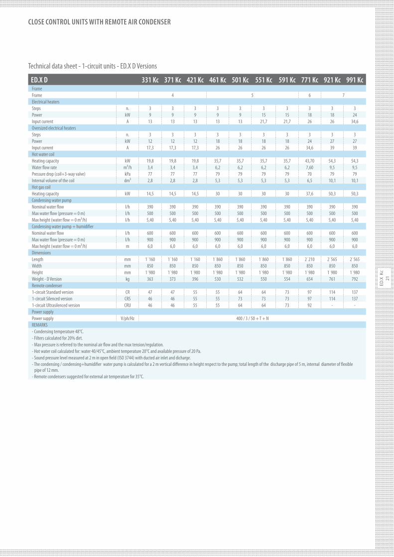
ED.X D 331 Kc 371 Kc 421 Kc 461 Kc 501 Kc 551 Kc 591 Kc 771 Kc 921 Kc 991 Kc
FrameFrame 4 5 6 7Electrical heatersSteps n. 3 3 3 3 3 3 3 3 3 3Power kW 9 9 9 9 9 15 15 18 18 24Input current A 13 13 13 13 13 21,7 21,7 26 26 34,6Oversized electrical heatersSteps n. 3 3 3 3 3 3 3 3 3 3Power kW 12 12 12 18 18 18 18 24 27 27Input current A 17,3 17,3 17,3 26 26 26 26 34,6 39 39Hot water coilHeating capacity kW 19,8 19,8 19,8 35,7 35,7 35,7 35,7 43,70 54,3 54,3Water $ow rate m³/h 3,4 3,4 3,4 6,2 6,2 6,2 6,2 7,60 9,5 9,5Pressure drop (coil+3-way valve) kPa 77 77 77 79 79 79 79 70 79 79Internal volume of the coil dm³ 2,8 2,8 2,8 5,3 5,3 5,3 5,3 6,5 10,1 10,1Hot gas coilHeating capacity kW 14,5 14,5 14,5 30 30 30 30 37,6 50,3 50,3Condensing water pump Nominal water $ow l/h 390 390 390 390 390 390 390 390 390 390Max water $ow (pressure = 0 m) l/h 500 500 500 500 500 500 500 500 500 500Max height (water $ow = 0 m³/h) l/h 5,40 5,40 5,40 5,40 5,40 5,40 5,40 5,40 5,40 5,40Condensing water pump + humidi#erNominal water $ow l/h 600 600 600 600 600 600 600 600 600 600Max water $ow (pressure = 0 m) l/h 900 900 900 900 900 900 900 900 900 900Max height (water $ow = 0 m³/h) m 6,0 6,0 6,0 6,0 6,0 6,0 6,0 6,0 6,0 6,0DimensionsLength mm 1˙160 1˙160 1˙160 1˙860 1˙860 1˙860 1˙860 2˙210 2˙565 2˙565Width mm 850 850 850 850 850 850 850 850 850 850Height mm 1˙980 1˙980 1˙980 1˙980 1˙980 1˙980 1˙980 1˙980 1˙980 1˙980Weight - D Version kg 363 373 396 530 532 550 554 654 761 792Remote condenser1-circuit Standard version CR 47 47 55 55 64 64 73 97 114 1371-circuit Silenced version CRS 46 46 55 55 73 73 73 97 114 1371-circuit Ultrasilenced version CRU 46 46 55 55 64 64 73 92 - -Power supplyPower supply V/ph/Hz 400 / 3 / 50 + T + NREMARKS- Condensing temperature 48°C.- Filters calculated for 20% dirt.- Max pressure is referred to the nominal air $ow and the max tension/regulation.- Hot water coil calculated for: water 40/45°C, ambient temperature 20°C and available pressure of 20 Pa.- Sound pressure level measured at 2 m in open #eld (ISO 3744) with ducted air inlet and dicharge.- The condensing / condensing+humidi#er water pump is calculated for a 2 m vertical di"erence in height respect to the pump; total length of the discharge pipe of 5 m, internal diameter of $exible pipe of 12 mm.- Remote condensers suggested for external air temperature for 35°C.
Technical data sheet - 1-circuit units - ED.X D Versions
ED
.X K
c
22
CLOSE CONTROL UNITS WITH REMOTE AIR CONDENSER
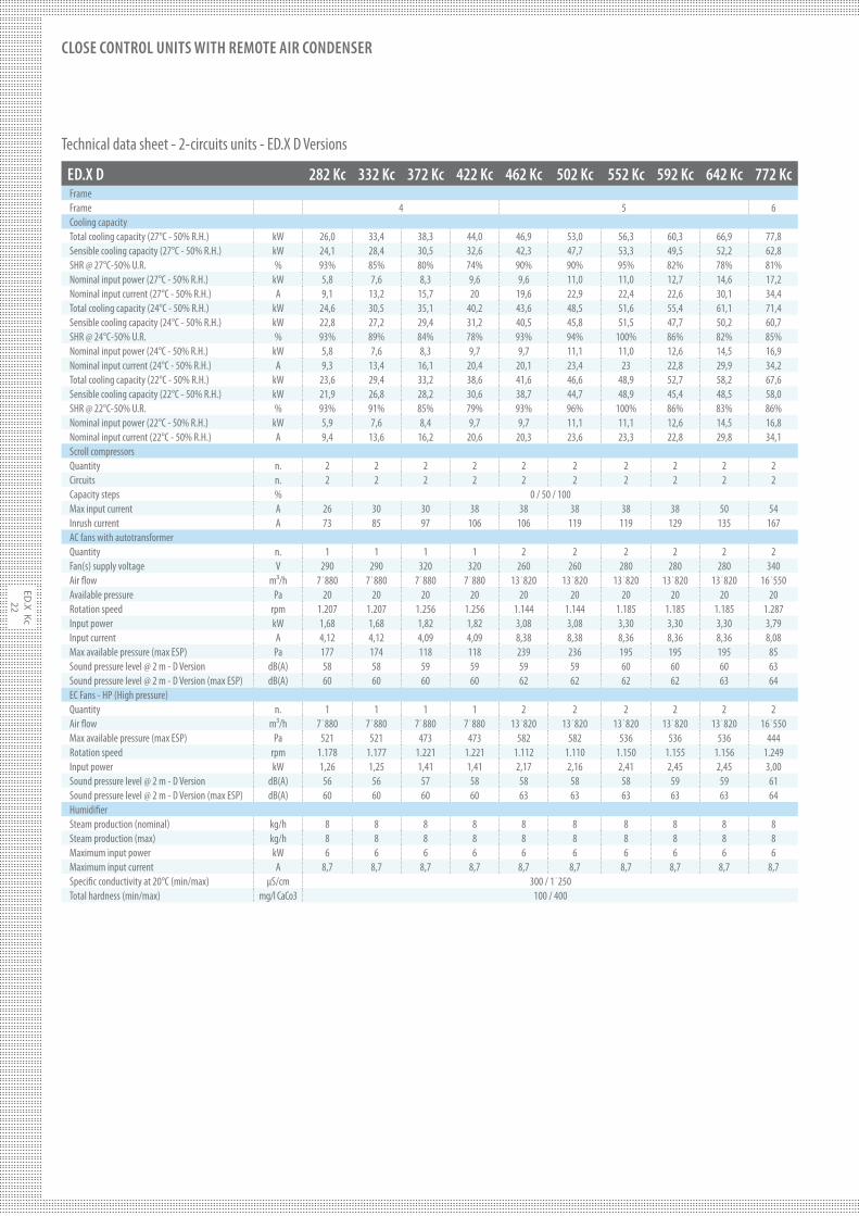
ED.X D 282 Kc 332 Kc 372 Kc 422 Kc 462 Kc 502 Kc 552 Kc 592 Kc 642 Kc 772 Kc
FrameFrame 4 5 6Cooling capacityTotal cooling capacity (27°C - 50% R.H.) kW 26,0 33,4 38,3 44,0 46,9 53,0 56,3 60,3 66,9 77,8Sensible cooling capacity (27°C - 50% R.H.) kW 24,1 28,4 30,5 32,6 42,3 47,7 53,3 49,5 52,2 62,8SHR @ 27°C-50% U.R. % 93% 85% 80% 74% 90% 90% 95% 82% 78% 81%Nominal input power (27°C - 50% R.H.) kW 5,8 7,6 8,3 9,6 9,6 11,0 11,0 12,7 14,6 17,2Nominal input current (27°C - 50% R.H.) A 9,1 13,2 15,7 20 19,6 22,9 22,4 22,6 30,1 34,4Total cooling capacity (24°C - 50% R.H.) kW 24,6 30,5 35,1 40,2 43,6 48,5 51,6 55,4 61,1 71,4Sensible cooling capacity (24°C - 50% R.H.) kW 22,8 27,2 29,4 31,2 40,5 45,8 51,5 47,7 50,2 60,7SHR @ 24°C-50% U.R. % 93% 89% 84% 78% 93% 94% 100% 86% 82% 85%Nominal input power (24°C - 50% R.H.) kW 5,8 7,6 8,3 9,7 9,7 11,1 11,0 12,6 14,5 16,9Nominal input current (24°C - 50% R.H.) A 9,3 13,4 16,1 20,4 20,1 23,4 23 22,8 29,9 34,2Total cooling capacity (22°C - 50% R.H.) kW 23,6 29,4 33,2 38,6 41,6 46,6 48,9 52,7 58,2 67,6Sensible cooling capacity (22°C - 50% R.H.) kW 21,9 26,8 28,2 30,6 38,7 44,7 48,9 45,4 48,5 58,0SHR @ 22°C-50% U.R. % 93% 91% 85% 79% 93% 96% 100% 86% 83% 86%Nominal input power (22°C - 50% R.H.) kW 5,9 7,6 8,4 9,7 9,7 11,1 11,1 12,6 14,5 16,8Nominal input current (22°C - 50% R.H.) A 9,4 13,6 16,2 20,6 20,3 23,6 23,3 22,8 29,8 34,1Scroll compressorsQuantity n. 2 2 2 2 2 2 2 2 2 2Circuits n. 2 2 2 2 2 2 2 2 2 2Capacity steps % 0 / 50 / 100Max input current A 26 30 30 38 38 38 38 38 50 54Inrush current A 73 85 97 106 106 119 119 129 135 167AC fans with autotransformerQuantity n. 1 1 1 1 2 2 2 2 2 2Fan(s) supply voltage V 290 290 320 320 260 260 280 280 280 340Air $ow m³/h 7˙880 7˙880 7˙880 7˙880 13˙820 13˙820 13˙820 13˙820 13˙820 16˙550Available pressure Pa 20 20 20 20 20 20 20 20 20 20Rotation speed rpm 1.207 1.207 1.256 1.256 1.144 1.144 1.185 1.185 1.185 1.287Input power kW 1,68 1,68 1,82 1,82 3,08 3,08 3,30 3,30 3,30 3,79Input current A 4,12 4,12 4,09 4,09 8,38 8,38 8,36 8,36 8,36 8,08Max available pressure (max ESP) Pa 177 174 118 118 239 236 195 195 195 85Sound pressure level @ 2 m - D Version dB(A) 58 58 59 59 59 59 60 60 60 63Sound pressure level @ 2 m - D Version (max ESP) dB(A) 60 60 60 60 62 62 62 62 63 64EC Fans - HP (High pressure)Quantity n. 1 1 1 1 2 2 2 2 2 2Air $ow m³/h 7˙880 7˙880 7˙880 7˙880 13˙820 13˙820 13˙820 13˙820 13˙820 16˙550Max available pressure (max ESP) Pa 521 521 473 473 582 582 536 536 536 444Rotation speed rpm 1.178 1.177 1.221 1.221 1.112 1.110 1.150 1.155 1.156 1.249Input power kW 1,26 1,25 1,41 1,41 2,17 2,16 2,41 2,45 2,45 3,00Sound pressure level @ 2 m - D Version dB(A) 56 56 57 58 58 58 58 59 59 61Sound pressure level @ 2 m - D Version (max ESP) dB(A) 60 60 60 60 63 63 63 63 63 64Humidi#erSteam production (nominal) kg/h 8 8 8 8 8 8 8 8 8 8Steam production (max) kg/h 8 8 8 8 8 8 8 8 8 8Maximum input power kW 6 6 6 6 6 6 6 6 6 6Maximum input current A 8,7 8,7 8,7 8,7 8,7 8,7 8,7 8,7 8,7 8,7Speci#c conductivity at 20°C (min/max) µS/cm 300 / 1˙250Total hardness (min/max) mg/l CaCo3 100 / 400
Technical data sheet - 2-circuits units - ED.X D Versions

ED
.X
Kc
23
CLOSE CONTROL UNITS WITH REMOTE AIR CONDENSER
ED.X D 282 Kc 332 Kc 372 Kc 422 Kc 462 Kc 502 Kc 552 Kc 592 Kc 642 Kc 772 Kc
FrameFrame 4 5 6Electrical heatersSteps n. 3 3 3 3 3 3 3 3 3 3Power kW 9 9 9 9 15 15 15 15 15 18Input current A 13 13 13 13 21,7 21,7 21,7 21,7 21,7 26Oversized electrical heatersSteps n. 3 3 3 3 3 3 3 3 3 3Power kW 12 12 12 12 18 18 18 18 18 24Input current A 17,3 17,3 17,3 17,3 26 26 26 26 26 34,6Hot water coilHeating capacity kW 19,8 19,8 19,8 19,8 35,7 35,7 35,7 35,7 35,7 43,7Water $ow rate m³/h 3,4 3,4 3,4 3,4 6,2 6,2 6,2 6,2 6,2 7,6Pressure drop (coil+3-way valve) kPa 77 77 77 77 79 79 79 79 79 70Internal volume of the coil dm³ 2,8 2,8 2,8 2,8 5,3 5,3 5,3 5,3 5,3 6,6Hot gas coilHeating capacity kW 15,4 15,4 15,4 15,4 29 29 29 29 29 37,1Condensing water pump Nominal water $ow l/h 390 390 390 390 390 390 390 390 390 390Max water $ow (pressure = 0 m) l/h 500 500 500 500 500 500 500 500 500 500Max height (water $ow = 0 m³/h) l/h 5,40 5,40 5,40 5,40 5,40 5,40 5,40 5,40 5,40 5,40Condensing water pump + humidi#erNominal water $ow l/h 600 600 600 600 600 600 600 600 600 600Max water $ow (pressure = 0 m) l/h 900 900 900 900 900 900 900 900 900 900Max height (water $ow = 0 m³/h) m 6,0 6,0 6,0 6,0 6,0 6,0 6,0 6,0 6,0 6,0DimensionsLength mm 1˙160 1˙160 1˙160 1˙160 1˙860 1˙860 1˙860 1˙860 1˙860 2˙210Width mm 850 850 850 850 850 850 850 850 850 850Height mm 1˙980 1˙980 1˙980 1˙980 1˙980 1˙980 1˙980 1˙980 1˙980 1˙980Weight - D Version kg 399 399 409 409 544 544 562 581 581 640Remote condenser1-circuit Standard version CR 2x19 2x22 2x22 2x29 2x29 2x34 2x34 2x34 2x47 2x551-circuit Silenced version CRS 2x18 2x23 2x30 2x30 2x30 2x34 2x34 2x34 2x46 2x551-circuit Ultrasilenced version CRU 2x17 2x22 2x29 2x29 2x29 2x34 2x34 2x34 2x46 2x552-circuit Standard version CR/2 40 40 50 50 70 70 70 70 80 1012-circuit Silenced version CRS/2 40 40 60 60 60 70 70 70 80 1012-circuit Ultrasilenced version CRU/2 40 40 46 60 60 70 70 70 80 100Power supplyPower supply V/ph/Hz 400 / 3 / 50 + T + NREMARKS- Condensing temperature 48°C.- Filters calculated for 20% dirt.- Max pressure is referred to the nominal air $ow and the max tension/regulation.- Hot water coil calculated for: water 40/45°C, ambient temperature 20°C and available pressure of 20 Pa.- Sound pressure level measured at 2 m in open #eld (ISO 3744) with ducted air inlet and dicharge.- The condensing / condensing+humidi#er water pump is calculated for a 2 m vertical di"erence in height respect to the pump; total length of the discharge pipe of 5 m, internal diameter of $exible pipe of 12 mm.- Remote condensers suggested for external air temperature for 35°C.
Technical data sheet - 2-circuits units - ED.X D Versions
ED
.X K
c
24
CLOSE CONTROL UNITS WITH REMOTE AIR CONDENSER
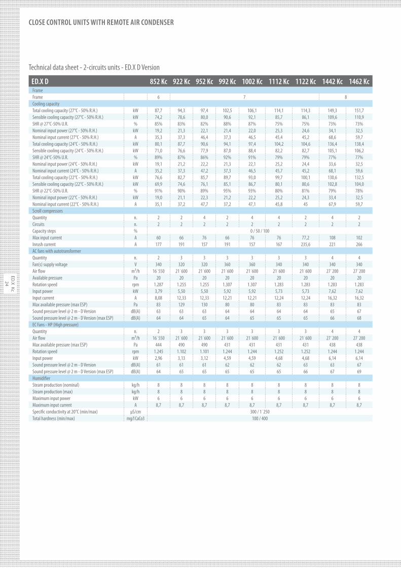
ED.X D 852 Kc 922 Kc 952 Kc 992 Kc 1002 Kc 1112 Kc 1122 Kc 1442 Kc 1462 Kc
FrameFrame 6 7 8Cooling capacityTotal cooling capacity (27°C - 50% R.H.) kW 87,7 94,3 97,4 102,5 106,1 114,1 114,3 149,3 151,7Sensible cooling capacity (27°C - 50% R.H.) kW 74,2 78,6 80,0 90,6 92,1 85,7 86,1 109,6 110,9SHR @ 27°C-50% U.R. % 85% 83% 82% 88% 87% 75% 75% 73% 73%Nominal input power (27°C - 50% R.H.) kW 19,2 21,3 22,1 21,4 22,0 25,3 24,6 34,1 32,5Nominal input current (27°C - 50% R.H.) A 35,3 37,3 46,4 37,3 46,5 45,4 45,2 68,6 59,7Total cooling capacity (24°C - 50% R.H.) kW 80,1 87,7 90,6 94,1 97,4 104,2 104,6 136,4 138,4Sensible cooling capacity (24°C - 50% R.H.) kW 71,0 76,6 77,9 87,0 88,4 82,2 82,7 105,1 106,2SHR @ 24°C-50% U.R. % 89% 87% 86% 92% 91% 79% 79% 77% 77%Nominal input power (24°C - 50% R.H.) kW 19,1 21,2 22,2 21,3 22,1 25,2 24,4 33,6 32,5Nominal input current (24°C - 50% R.H.) A 35,2 37,3 47,2 37,3 46,5 45,7 45,2 68,1 59,6Total cooling capacity (22°C - 50% R.H.) kW 76,6 82,7 85,7 89,7 93,0 99,7 100,1 130,6 132,5Sensible cooling capacity (22°C - 50% R.H.) kW 69,9 74,6 76,1 85,1 86,7 80,1 80,6 102,8 104,0SHR @ 22°C-50% U.R. % 91% 90% 89% 95% 93% 80% 81% 79% 78%Nominal input power (22°C - 50% R.H.) kW 19,0 21,1 22,3 21,2 22,2 25,2 24,3 33,4 32,5Nominal input current (22°C - 50% R.H.) A 35,1 37,2 47,7 37,2 47,1 45,8 45 67,9 59,7Scroll compressorsQuantity n. 2 2 4 2 4 4 2 4 2Circuits n. 2 2 2 2 2 2 2 2 2Capacity steps % 0 / 50 / 100Max input current A 60 66 76 66 76 76 77,2 108 102Inrush current A 177 191 157 191 157 167 235,6 221 266AC fans with autotransformerQuantity n. 2 3 3 3 3 3 3 4 4Fan(s) supply voltage V 340 320 320 360 360 340 340 340 340Air $ow m³/h 16˙550 21˙600 21˙600 21˙600 21˙600 21˙600 21˙600 27˙200 27˙200Available pressure Pa 20 20 20 20 20 20 20 20 20Rotation speed rpm 1.287 1.255 1.255 1.307 1.307 1.283 1.283 1.283 1.283Input power kW 3,79 5,50 5,50 5,92 5,92 5,73 5,73 7,62 7,62Input current A 8,08 12,33 12,33 12,21 12,21 12,24 12,24 16,32 16,32Max available pressure (max ESP) Pa 83 129 130 80 80 83 83 83 83Sound pressure level @ 2 m - D Version dB(A) 63 63 63 64 64 64 64 65 67Sound pressure level @ 2 m - D Version (max ESP) dB(A) 64 64 65 64 65 65 65 66 68EC Fans - HP (High pressure)Quantity n. 2 3 3 3 3 3 3 4 4Air $ow m³/h 16˙550 21˙600 21˙600 21˙600 21˙600 21˙600 21˙600 27˙200 27˙200Max available pressure (max ESP) Pa 444 490 490 431 431 431 431 438 438Rotation speed rpm 1.245 1.102 1.101 1.244 1.244 1.252 1.252 1.244 1.244Input power kW 2,96 3,13 3,12 4,59 4,59 4,68 4,68 6,14 6,14Sound pressure level @ 2 m - D Version dB(A) 61 61 61 62 62 62 63 63 67Sound pressure level @ 2 m - D Version (max ESP) dB(A) 64 65 65 65 65 65 66 67 69Humidi#erSteam production (nominal) kg/h 8 8 8 8 8 8 8 8 8Steam production (max) kg/h 8 8 8 8 8 8 8 8 8Maximum input power kW 6 6 6 6 6 6 6 6 6Maximum input current A 8,7 8,7 8,7 8,7 8,7 8,7 8,7 8,7 8,7Speci#c conductivity at 20°C (min/max) µS/cm 300 / 1˙250Total hardness (min/max) mg/l CaCo3 100 / 400
Technical data sheet - 2-circuits units - ED.X D Version
ED
.X
Kc
25
CLOSE CONTROL UNITS WITH REMOTE AIR CONDENSER
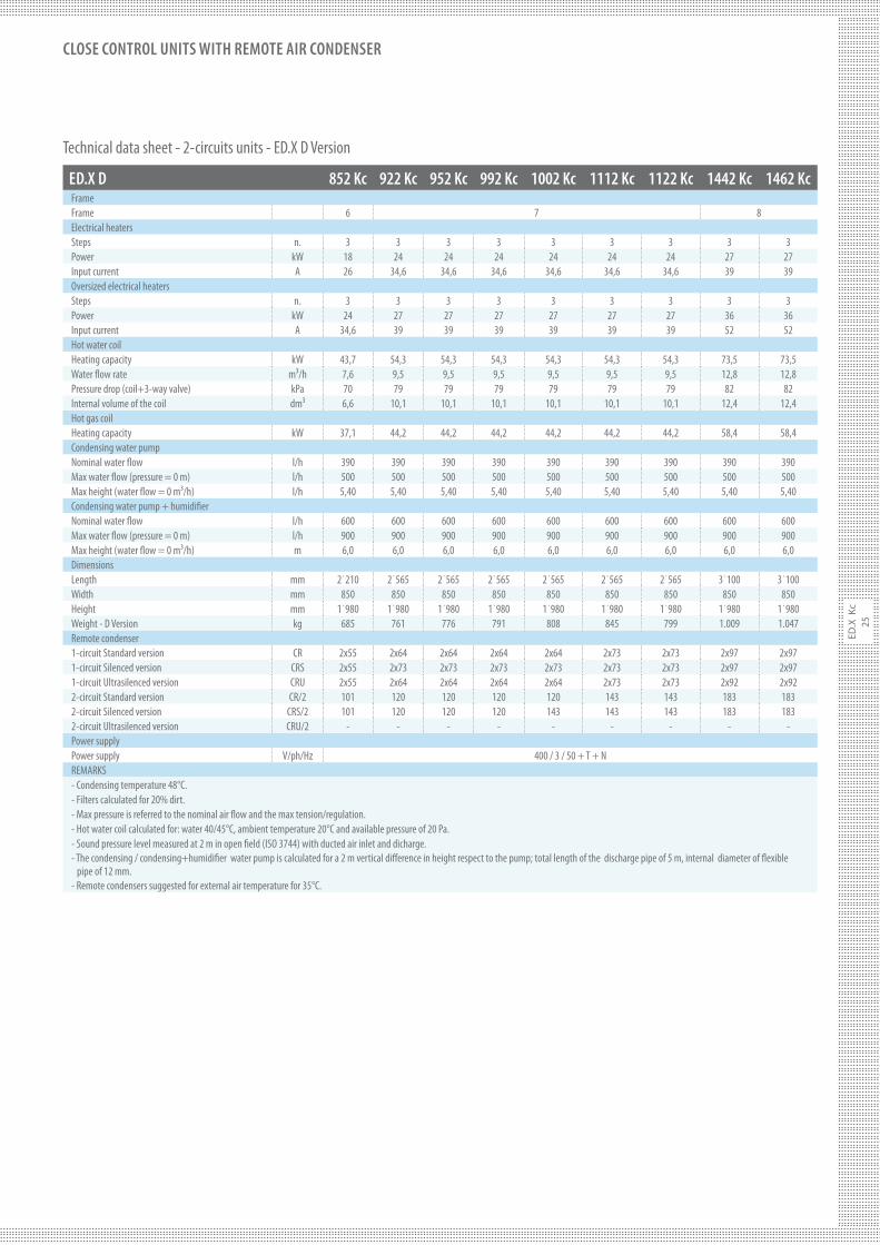
ED.X D 852 Kc 922 Kc 952 Kc 992 Kc 1002 Kc 1112 Kc 1122 Kc 1442 Kc 1462 Kc
FrameFrame 6 7 8Electrical heatersSteps n. 3 3 3 3 3 3 3 3 3Power kW 18 24 24 24 24 24 24 27 27Input current A 26 34,6 34,6 34,6 34,6 34,6 34,6 39 39Oversized electrical heatersSteps n. 3 3 3 3 3 3 3 3 3Power kW 24 27 27 27 27 27 27 36 36Input current A 34,6 39 39 39 39 39 39 52 52Hot water coilHeating capacity kW 43,7 54,3 54,3 54,3 54,3 54,3 54,3 73,5 73,5Water $ow rate m³/h 7,6 9,5 9,5 9,5 9,5 9,5 9,5 12,8 12,8Pressure drop (coil+3-way valve) kPa 70 79 79 79 79 79 79 82 82Internal volume of the coil dm³ 6,6 10,1 10,1 10,1 10,1 10,1 10,1 12,4 12,4Hot gas coilHeating capacity kW 37,1 44,2 44,2 44,2 44,2 44,2 44,2 58,4 58,4Condensing water pump Nominal water $ow l/h 390 390 390 390 390 390 390 390 390Max water $ow (pressure = 0 m) l/h 500 500 500 500 500 500 500 500 500Max height (water $ow = 0 m³/h) l/h 5,40 5,40 5,40 5,40 5,40 5,40 5,40 5,40 5,40Condensing water pump + humidi#erNominal water $ow l/h 600 600 600 600 600 600 600 600 600Max water $ow (pressure = 0 m) l/h 900 900 900 900 900 900 900 900 900Max height (water $ow = 0 m³/h) m 6,0 6,0 6,0 6,0 6,0 6,0 6,0 6,0 6,0DimensionsLength mm 2˙210 2˙565 2˙565 2˙565 2˙565 2˙565 2˙565 3˙100 3˙100Width mm 850 850 850 850 850 850 850 850 850Height mm 1˙980 1˙980 1˙980 1˙980 1˙980 1˙980 1˙980 1˙980 1˙980Weight - D Version kg 685 761 776 791 808 845 799 1.009 1.047Remote condenser1-circuit Standard version CR 2x55 2x64 2x64 2x64 2x64 2x73 2x73 2x97 2x971-circuit Silenced version CRS 2x55 2x73 2x73 2x73 2x73 2x73 2x73 2x97 2x971-circuit Ultrasilenced version CRU 2x55 2x64 2x64 2x64 2x64 2x73 2x73 2x92 2x922-circuit Standard version CR/2 101 120 120 120 120 143 143 183 1832-circuit Silenced version CRS/2 101 120 120 120 143 143 143 183 1832-circuit Ultrasilenced version CRU/2 - - - - - - - - -Power supplyPower supply V/ph/Hz 400 / 3 / 50 + T + NREMARKS- Condensing temperature 48°C.- Filters calculated for 20% dirt.- Max pressure is referred to the nominal air $ow and the max tension/regulation.- Hot water coil calculated for: water 40/45°C, ambient temperature 20°C and available pressure of 20 Pa.- Sound pressure level measured at 2 m in open #eld (ISO 3744) with ducted air inlet and dicharge.- The condensing / condensing+humidi#er water pump is calculated for a 2 m vertical di"erence in height respect to the pump; total length of the discharge pipe of 5 m, internal diameter of $exible pipe of 12 mm.- Remote condensers suggested for external air temperature for 35°C.
Technical data sheet - 2-circuits units - ED.X D Version