cleaning robot
DESCRIPTION
CleaningTRANSCRIPT

[Type the document title]
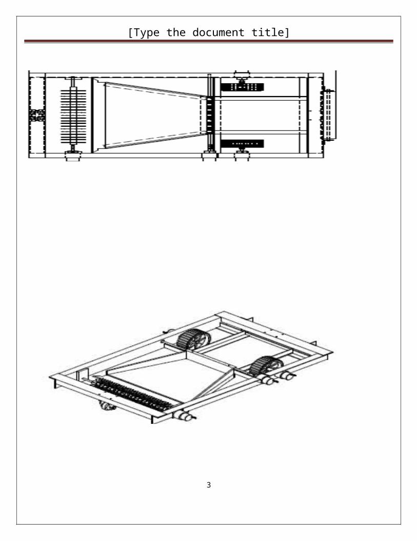
Floor Cleaning Robot
Introduction
The idea behind domestic robotic devices like the Floor Washing Robot is to liberate people from unpleasant daily chores and free up their time. A cleaning robot can be used not only for private homes but also in offices, stores, etc. Therobot cleaner changes the way we clean. Floor cleaning robots also work great in collaboration with a dedicated cleaning devices
1

[Type the document title]
2
[Type the document title]
Block Diagram
3
ARM7
POWER SUPPLY
RELAY 1 ROBBOT MOTOR 1
RE LAY 2 ROBBOT MOTOR 2
RELAY 3 ROBBOT MOTOR 3
RELAY 4 ROBBOT MOTOR 4
DTMFDECODER
3.5 AUDIOJACK
MOBILE2
KEYPAD
RTC
LCD
MANNUALMODE SWITCH
AUTOMODE SWITCH

[Type the document title]
Circuit diagram & Description
Specification of Components used:
4
[Type the document title]
Types of Power Supply
There are many types of power supply. Most are designed to convert high voltage AC mains electricity to a suitable DC voltage supply for electronics circuits and other devices. A power supply can by broken down into a series of blocks, each of which performs a particular function.
A 5V regulated supply
.
Each of the blocks is described in more detail below:
Transformer - steps down high voltage AC mains to low voltage AC. Rectifier - converts AC to DC, but the DC output is varying. Smoothing - smooths the DC from varying greatly to a small ripple. Regulator - eliminates ripple by setting DC output to a fixed voltage.
5

[Type the document title]
Transformer
Transformer circuit symbol
Transformers convert AC electricity from one voltage to another with little loss of power. Transformers work only with AC and this is one of the reasons why mains electricity is AC.
6

[Type the document title]
Step-up transformers increase voltage, step-down transformers reduce voltage. Most power supplies use a step-down transformer to reduce the dangerously high mains voltage (230V in UK) to a safer low voltage.
The input coil is called the primary and the output coil is called the secondary. There is no electrical connection between the two coils, instead they are linked by an alternating magnetic field created in the soft-iron core of the transformer. The two lines in the middle of the circuit symbol represent the core.
Transformers waste very little power so the power out is (almost) equal to the power in. Note that as voltage is stepped down current is stepped up.
The ratio of the number of turns on each coil, called the turns ratio, determines the ratio of the voltages. A step-down transformer has a large number of turns on its primary (input) coil which is connected to the high voltage mains supply, and a small number of turns on its secondary (output) coil to give a low output voltage.
turns ratio = Vp
= Np
and power out = power in
Vs Ns Vs × Is = Vp × Ip
Vp = primary (input) voltageNp = number of turns on primary coilIp = primary (input) current
Vs = secondary (output) voltageNs = number of turns on secondary coilIs = secondary (output) current
Bridge rectifierA bridge rectifier can be made using four individual diodes, but it is also available in special packages containing the four diodes required. It is called a full-wave rectifier because it uses all the AC wave (both positive and negative sections). 1.4V is used up in the bridge rectifier because each diode uses 0.7V when conducting and there are always two diodes conducting, as shown in the diagram below. Bridge rectifiers are rated by the maximum current they can pass and the maximum reverse voltage they can withstand (this must be at least three times the supply RMS voltage so the rectifier can withstand the peak voltages). Please see the Diodes page for more details, including pictures of bridge rectifier
Root Mean Square (RMS) Values
The value of an AC voltage is continually changing from zero up to the positive peak, through zero to the negative peak and back to zero again. Clearly for most of the time it is less than the peak voltage, so this is not a good measure of its real effect.
7

[Type the document title]
Instead we use the root mean square voltage (VRMS) which is 0.7 of the peak voltage (Vpeak):
VRMS = 0.7 × Vpeak and Vpeak = 1.4 × VRMS
These equations also apply to current. They are only true for sine waves (the most common type of AC) because the 0.7 and 1.4 are different values for other shapes.
The RMS value is the effective value of a varying voltage or current. It is the equivalent steady DC (constant) value which gives the same effect.
For example a lamp connected to a 6V RMS AC supply will light with the same brightness when connected to a steady 6V DC supply. However, the lamp will be dimmer if connected to a 6V peak AC supply because the RMS value of this is only 4.2V (it is equivalent to a steady 4.2V DC).
8

[Type the document title]
You may find it helps to think of the RMS value as a sort of average, but please remember that it is NOT really the average! In fact the average voltage (or current) of an AC signal is zero because the positive and negative parts exactly cancel out
Bridge rectifierAlternate pairs of diodes conduct, changing overthe connections so the alternating directions ofAC are converted to the one direction of DC.
Smoothing
Smoothing is performed by a large value electrolytic capacitor connected across the DC supply to act as a reservoir, supplying current to the output when the varying DC voltage from the rectifier is falling. The diagram shows the unsmoothed varying DC (dotted line) and the smoothed DC (solid line). The capacitor charges quickly near the peak of the varying DC, and then discharges as it supplies current to the output.
9

[Type the document title]
Note that smoothing significantly increases the average DC voltage to almost the peak value (1.4 × RMS value). For example 6V RMS AC is rectified to full wave DC of about 4.6V RMS (1.4V is lost in the bridge rectifier), with smoothing this increases to almost the peak value giving 1.4 × 4.6 = 6.4V smooth DC.
Smoothing is not perfect due to the capacitor voltage falling a little as it discharges, giving a small ripple voltage. For many circuits a ripple which is 10% of the supply voltage is satisfactory and the equation below gives the required value for the smoothing capacitor. A larger capacitor will give less ripple. The capacitor value must be doubled when smoothing half-wave DC.
Smoothing capacitor for 10% ripple, C =
5 × Io
Vs × f
C = smoothing capacitance in farads (F)Io = output current from the supply in amps (A)Vs = supply voltage in volts (V), this is the peak value of the unsmoothed DCf = frequency of the AC supply in hertz (Hz), 50Hz in the UK
Electrolytic Capacitors
10

[Type the document title]
Examples: Circuit symbol:
Electrolytic capacitors are polarised and they must be connected the correct way round, at least one of their leads will be marked + or -. They are not damaged by heat when soldering.
There are two designs of electrolytic capacitors; axial where the leads are attached to each end (220µF in picture) and radial where both leads are at the same end (10µF in picture). Radial capacitors tend to be a little smaller and they stand upright on the circuit board.
It is easy to find the value of electrolytic capacitors because they are clearly printed with their capacitance and voltage rating. The voltage rating can be quite low (6V for example) and it should always be checked when selecting an electrolytic capacitor. If the project parts list does not specify a voltage, choose a capacitor with a rating which is greater than the project's power supply voltage. 25V is a sensible minimum for most battery circuits.
Voltage regulator
11

[Type the document title]
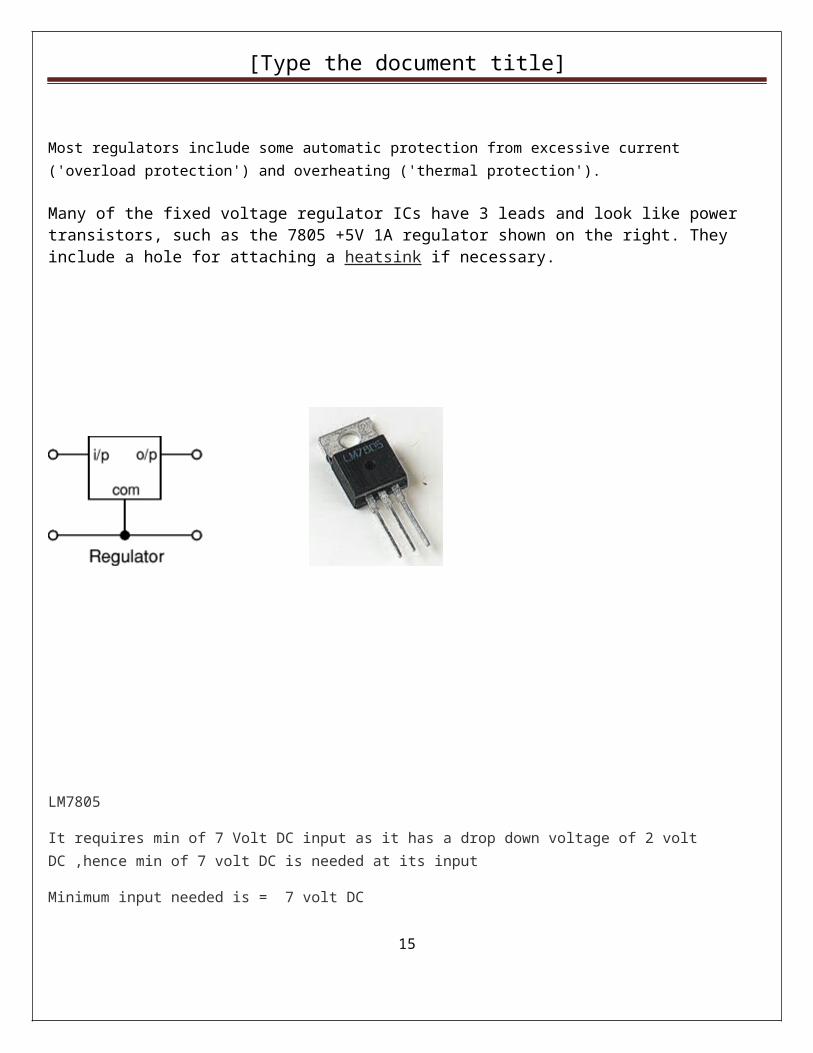
Voltage regulator ICs are available with fixed (typically 5, 12 and 15V) or variable output voltages. They are also rated by the maximum current they can pass. Negative voltage regulators are available, mainly for use in dual supplies. Most regulators include some automatic protection from excessive current ('overload protection') and overheating ('thermal protection').
Many of the fixed voltage regulator ICs have 3 leads and look like power transistors, such as the 7805 +5V 1A regulator shown on the right. They include a hole for attaching a heatsink if necessary.
LM7805
It requires min of 7 Volt DC input as it has a drop down voltage of 2 volt DC ,hence min of 7 volt DC is needed at its input
Minimum input needed is = 7 volt DC
12

[Type the document title]
Filter
A Smoothing Capacitor is used to generate ripple free DC. Smoothing capacitor is also called Filter capacitor and its function is to convert half wave / full wave output of the rectifier into smooth DC. The power rating and the capacitance are two important aspects to be considered while selecting the smoothing capacitor. The power rating must be greater than the off load output voltage of the power supply. The capacitance value determines the amount of ripples that appear in the DC output when the load takes current. For example, a full wave rectified DC output obtained from 50Hz AC mains operating a circuit that is drawing 100 mA current will have a ripple of 700 mV peak-to-peak in the filter capacitor rated 1000 uF. The ripple that appears in the capacitor is directly proportional to the load current and is inversely proportional to the capacitance value. It is better to keep the ripple below 1.5 V peak-to-peaks under full load condition. So a high value capacitor (1000 uF or 2200 uF) rated 25 volts or more must be used to get a ripple free DC output. If ripple is excess it will affect the functioning of the circuit especially RF and IR circuits.
Rectifier Circuit
As 2 diodes are ON in each half cycle, they each has a drop down voltage of 1 volt apron, hence,
Min output of rectifier circuit is= 7volt
Min input needed is = 9 Volt
Transformed
We will need a step down tansformer of that will decrease a voltage from 230 volt AC to min of 9 Volt AC , hence we have used a 12 volt AC step down transformer
13

[Type the document title]
Microcontroller 89V51RD2:
P89V51RD2 Features
64 KB flash memory
1 KB RAM
32 I/O lines
Programmable counter array
In System Application
Three 16-bit Timer/Counter
Accumulator:
ACC is the accumulator register. It is an 8 bit register. It is most versatile and holds sources
operand and receives the result of arithmetic operations including addition, subtraction, integer
multiplication, division and Boolean bit manipulations.
It is also used for data transfer between 8051 and any external memory. Several functions like
rotate, test etc. apply specifically on the accumulator.
Arithmetic and Logic Unit (ALU):
The ALU can perform arithmetic and logic operations on eight bit data. It can perform
arithmetic operations like addition, subtraction, multiplication, division and logical operations like AND, OR,
EX – OR, complement, rotate etc.
Program Status Word (PSW) and Flags:
14
[Type the document title]
Many instructions affect the status of flags. In order to address these flags conveniently they are
grouped to from the program status word. PSW contain Carry flag ( CY) , Auxiliary carry flag ( AC ), User
defined Flag 0 (F0 ) , register bank selections flag (RS0,RS1) Overflow flag( OV ) Parity flag (p) .Flags are 1 bit
registers provided to store the results of some instructions. A Flag is a flip flop that indicates some
condition produced by the execution of an instruction.
RST:
Reset input. A high on his pin two machine cycles while the oscillator is running resets the device.
This pin drives high for 98 oscillator periods after the Watchdog times out. The DISRTO bit in SFR AUXR
(address 8 EH) can be used to disable this feature. In the default state of bit DISRTO, the RESET HIGH out
feature is enabled.
Program Counter (PC):
It is a 16-bit register. It is used to hold the address of a byte in the memory. It keeps the track of
the execution of the program. The program instruction bytes are fetched from locations in memory that
are addressed by the Program counter.
The Stack and Stack Pointer:
The stack is a reserved area of the memory in RAM where temporary information may be stored.
An 8 – bit stack pointer is used to hold the address of the most recent stack entry. This location, which has
the most recent entry, is called as the top of the stack.
Special Function Registers:
A map of the on-chip memory area called the Special Function Register (SFR) space is shown in
Table 5-1. Note that not all of the addresses are occupied, and unoccupied addresses may not be
implemented on the chip. Read accesses to these addresses will in general return random data, and write
accesses will have an indeterminate effect. User software should not write 1s to these unlisted locations,
15

[Type the document title]
since they may be used in future products to invoke new features. In that case, the reset or inactive values
of the new bits will always be 0.
Timer 2 Registers: Control and status bits are contained in registers T2CON (shown in Table 5- 2)
and T2MOD (shown in Table 10-2) for Timer 2. The register pair (RCAP2H, RCAP2L) are the Capture/Reload
registers for Timer 2 in 16-bit capture mode or 16-bit auto-reload mode. Interrupt Registers: The individual
interrupt enable bits are in the IE register. Two priorities can be set for each of the six interrupt sources in
the IP register.
Input and output ports:
The I/O circuit of microcontroller is totally versatile. It connects the microcontroller to external
world. The microcontroller 89v51 has four i/o ports i.e. 24 lines out of 32 port lines are for one of the two
entirely different function so, although microcontroller is 40 pin chip, it appears to have 64 pins.
As two functions are multiplexed, in order to decide which function is supported we need to see
how the circuit is connected and what software commands are used to program the pin.
The microcontroller has four ports named as p0, p1, p2, p3. All these ports are bi-directional.
DC Motor
Geared DC motors can be defined as an extension of DC motor which already had its Insight details
demystified here. A geared DC Motor has a gear assembly attached to the motor. The speed of motor is
counted in terms of rotations of the shaft per minute and is termed as RPM .The gear assembly helps in
increasing the torque and reducing the speed. Using the correct combination of gears in a gear motor, its
speed can be reduced to any desirable figure. This concept where gears reduce the speed of the vehicle but
16

[Type the document title]
increase its torque is known as gear reduction. This Insight will explore all the minor and major details that
make the gear head and hence the working of geared DC motor.
External Structure
At the first sight, the external structure of a DC geared motor looks as a straight expansion over the simple DC
ones.
17

[Type the document title]
The lateral view of the motor shows the outer protrudes of the gear head. A nut is placed near the shaft which
helps in mounting the motor to the other parts of the assembly.
18

[Type the document title]
Also, an internally threaded hole is there on the shaft to allow attachments or extensions such as wheel to be
attached to the motor
19

[Type the document title]
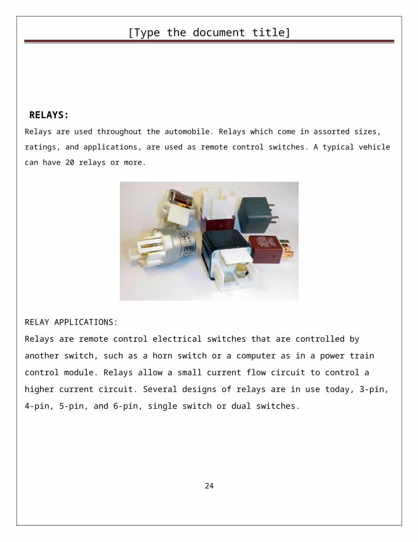
RELAYS:Relays are used throughout the automobile. Relays which come in assorted sizes, ratings, and applications, are used as
remote control switches. A typical vehicle can have 20 relays or more.
RELAY APPLICATIONS:
Relays are remote control electrical switches that are controlled by another switch, such as a horn switch or a
computer as in a power train control module. Relays allow a small current flow circuit to control a higher
current circuit. Several designs of relays are in use today, 3-pin, 4-pin, 5-pin, and 6-pin, single switch or dual
switches.
20

[Type the document title]
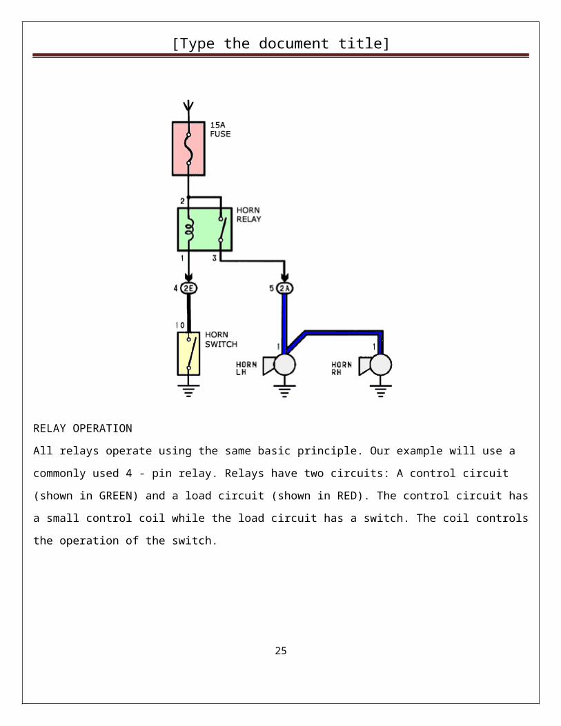
RELAY OPERATION
All relays operate using the same basic principle. Our example will use a commonly used 4 - pin relay. Relays
have two circuits: A control circuit (shown in GREEN) and a load circuit (shown in RED). The control circuit
has a small control coil while the load circuit has a switch. The coil controls the operation of the switch.
21

[Type the document title]
RELAY ENERGIZED (ON)
Current flowing through the control circuit coil (pins 1 and 3) creates a small magnetic field which causes the
switch to close, pins 2 and 4. The switch, which is part of the load circuit, is used to control an electrical circuit
that may connect to it. Current now flows through pins 2 and 4 shown in RED, when the relay is energized.
RELAY DE-ENERGIZED (OFF)
When current stops flowing through the control circuit, pins 1 and 3, the relay becomes de-energized. Without
the magnetic field, the switch opens and current is prevented from flowing through pins 2 and 4. The relay is
now OFF.
22

[Type the document title]
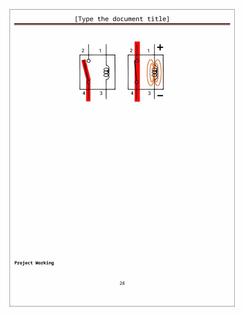
RELAY OPERATION :
When no voltage is applied to pin 1, there is no current flow through the coil. No current means no magnetic
field is developed, and the switch is open. When voltage is supplied to pin 1, current flow though the coil
creates the magnetic field needed to close the switch allowing continuity between pins 2 and 4.
23
[Type the document title]
Project Working
The working of this project can be explained in two modes
In this mode the output of headphone Jack of Mobile 2 is connected to DTMF Decoder IC 8870.Thus when any key pressed from Mobile 1 during the call, will create a DTMF frequency pattern at the headphone output of Mobile 2. Hence the DTMF decoder will create a corresponding binary output as per the data sheet. This binary code will act as a controlling signal for robot, microcontroller will continuously check for this controlling signal and once it receive this code; it will turn ON the corresponding relay and hence the motor . In this way we can move all motors of robot in all three axis direction as per our need
Autonomous modeIn this mode the robot will follow the set programmed path
Timer Base Mode
In this mode the robot will follow the RTC time and will WORK ACCORDINGLY
.
24
[Type the document title]
Robot Flowchart
25
INITIALIZATION
WAIT FOR USER COMANDS
CHECK PC CODE
CHECK FOR COMMANDS
Is 1 Press?
* Press= Motor1 CLK0 Press= Motor1 Stop# Press= Motor1 ACLK
Is 2 Press?
Is 3 Press?
Is 4 Press?
START
* Press= Motor 2 CLK0 Press= Motor 2 Stop# Press= Motor 2 ACLK
* Press= Motor3 CLK0 Press= Motor3 Stop# Press= Motor3 ACLK
* Press= Motor4 CLK0 Press= Motor4 Stop# Press= Motor4 ACLK

[Type the document title]
26
Is 5 Press?
STOP
* Press= Motor5 CLK0 Press= Motor5 Stop# Press= Motor5 ACLK

[Type the document title]
Applications and Advantages:
1. It can be used in Production industry.
2. In mass production.
3. In Automobile Industry.
Future Development:
1. Can make a wireless using RF technology
2. We can add more features like drilling, welding
27
[Type the document title]
Bibliography:
1. The 8051 Microcontroller- [Architecture, Programming, and Applications]
By
Kenneth Ayala
2. Micro Controllers – [Theory and Applications]
By
Ajay V. Deshmukh
Tata McGraw. Hill. 8.
3. MICROCONTROLLERS-[Textbook]
By
Vijay N. Kukre
Tech-Max
28

[Type the document title]
WEB-SITES:-
www.datasheetarchieve.com
www.maxim-ic.com
www.alldatasheet.com/
www.nxp.com/-Philips
29