in-pipe cleaning mechanical system for dewalop robot
TRANSCRIPT
In-pipe Cleaning Mechanical System forDeWaLoP Robot - Developing Water Loss Prevention
Luis A. Mateos and Markus Vincze
Abstract— After more than 50 years the connections betweenfresh water pipes (800-1000mm diameter) need to be repaireddue to aging and dissolution of the filling material. Only inVienna 3000km of pipes need to be improved, which requiresa robotic solution. This paper describes the in-pipe cleaningsystem used by the DeWaLoP robot, its configurations, mechan-ical properties, kinematics and preliminary cleaning test results.This new approach for in-pipe cleaning mechanism, mimickinga double cylindrical robot. With an end effector, such as apower tool (grinder) mounted on one of the arms, while a drivewheel is located on the second arm, enabling rotation to theentire cleaning system with high resolution steps. Additionaly,our approach prevents the cleaning mechanism from damagingthe pipe, reacting to overcome any excessive force. To do so,its mechanical arrangement includes a suspension system onthe double cylindrical arm to react similar as the arms froma human operator when working with a cleaning tool overcorroded surfaces, enabling the tool to retract if vibrates orjumps back, instead of passing all these noxious forces to thepipe.
I. INTRODUCTION
Fresh water pipelines are prone to damages due to aging,excessive traffic and geological changes. Resulting fromthese damages, the pipe-joints may not be completely her-metic and water loss along the pipeline may occur. Leakageis not only a problem in terms of wasting an importantresource, it also results in an economic loss in form ofdamages to the supplying system and to foundations of roadsand buildings too [1] [2].
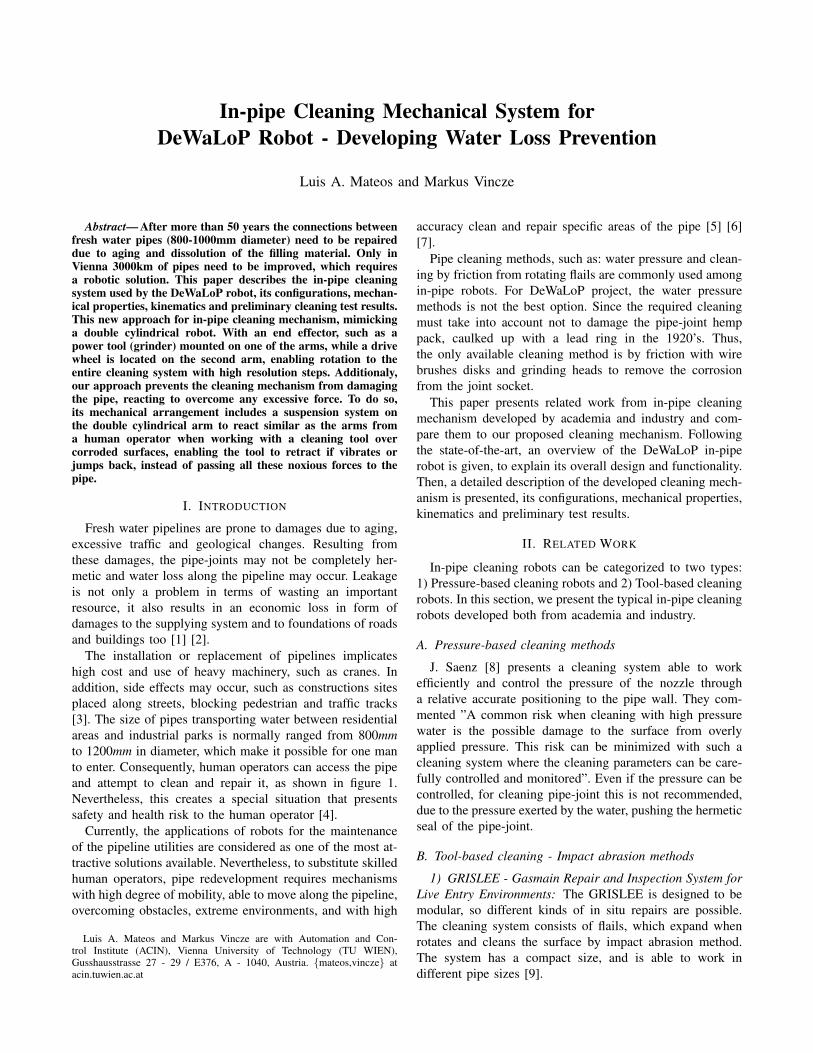
The installation or replacement of pipelines implicateshigh cost and use of heavy machinery, such as cranes. Inaddition, side effects may occur, such as constructions sitesplaced along streets, blocking pedestrian and traffic tracks[3]. The size of pipes transporting water between residentialareas and industrial parks is normally ranged from 800mmto 1200mm in diameter, which make it possible for one manto enter. Consequently, human operators can access the pipeand attempt to clean and repair it, as shown in figure 1.Nevertheless, this creates a special situation that presentssafety and health risk to the human operator [4].
Currently, the applications of robots for the maintenanceof the pipeline utilities are considered as one of the most at-tractive solutions available. Nevertheless, to substitute skilledhuman operators, pipe redevelopment requires mechanismswith high degree of mobility, able to move along the pipeline,overcoming obstacles, extreme environments, and with high
Luis A. Mateos and Markus Vincze are with Automation and Con-trol Institute (ACIN), Vienna University of Technology (TU WIEN),Gusshausstrasse 27 - 29 / E376, A - 1040, Austria. {mateos,vincze} atacin.tuwien.ac.at
accuracy clean and repair specific areas of the pipe [5] [6][7].
Pipe cleaning methods, such as: water pressure and clean-ing by friction from rotating flails are commonly used amongin-pipe robots. For DeWaLoP project, the water pressuremethods is not the best option. Since the required cleaningmust take into account not to damage the pipe-joint hemppack, caulked up with a lead ring in the 1920’s. Thus,the only available cleaning method is by friction with wirebrushes disks and grinding heads to remove the corrosionfrom the joint socket.
This paper presents related work from in-pipe cleaningmechanism developed by academia and industry and com-pare them to our proposed cleaning mechanism. Followingthe state-of-the-art, an overview of the DeWaLoP in-piperobot is given, to explain its overall design and functionality.Then, a detailed description of the developed cleaning mech-anism is presented, its configurations, mechanical properties,kinematics and preliminary test results.
II. RELATED WORK
In-pipe cleaning robots can be categorized to two types:1) Pressure-based cleaning robots and 2) Tool-based cleaningrobots. In this section, we present the typical in-pipe cleaningrobots developed both from academia and industry.
A. Pressure-based cleaning methods
J. Saenz [8] presents a cleaning system able to workefficiently and control the pressure of the nozzle througha relative accurate positioning to the pipe wall. They com-mented ”A common risk when cleaning with high pressurewater is the possible damage to the surface from overlyapplied pressure. This risk can be minimized with such acleaning system where the cleaning parameters can be care-fully controlled and monitored”. Even if the pressure can becontrolled, for cleaning pipe-joint this is not recommended,due to the pressure exerted by the water, pushing the hermeticseal of the pipe-joint.
B. Tool-based cleaning - Impact abrasion methods
1) GRISLEE - Gasmain Repair and Inspection System forLive Entry Environments: The GRISLEE is designed to bemodular, so different kinds of in situ repairs are possible.The cleaning system consists of flails, which expand whenrotates and cleans the surface by impact abrasion method.The system has a compact size, and is able to work indifferent pipe sizes [9].
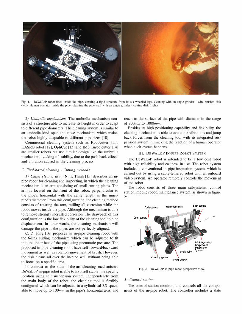
Fig. 1. DeWaLoP robot fixed inside the pipe, creating a rigid structure from its six wheeled-legs, cleaning with an angle grinder - wire brushes disk(left). Human operator inside the pipe, cleaning the pipe wall with an angle grinder - cutting disk (right).
2) Umbrella mechanism: The umbrella mechanism con-sists of a structure able to increase its height in order to adaptto different pipe diameters. The cleaning system is similar toan umbrella kind open-and-close mechanism, which makesthe robot highly adaptable to different pipe sizes [10].
Commercial cleaning system such as Robocutter [11],KASRO robot [12], OptiCut [13] and IMS Turbo cutter [14]are smaller robots but use similar design like the umbrellamechanism. Lacking of stability, due to the push back effectsand vibration caused in the cleaning process.
C. Tool-based cleaning - Cutting methods
1) Cutter cleaner arm: N. T. Thinh [15] describes an in-pipe robot for cleaning and inspecting, in which the cleaningmechanism is an arm consisting of small cutting plates. Thearm is located on the front of the robot, perpendicular tothe pipe’s horizontal with the same length as the inner-pipe’s diameter. From this configuration, the cleaning methodconsists of rotating the arm, milling all corrosion while therobot moves inside the pipe. Although the mechanism is ableto remove strongly incrusted corrosion. The drawback of thisconfiguration is the low flexibility of the cleaning tool to pipedisplacement. In other words, the cleaning mechanism willdamage the pipe if the pipes are not perfectly aligned.
C. D. Jung [16] proposes an in-pipe cleaning robot withthe 6-link sliding mechanism which can be adjusted to fitinto the inner face of the pipe using pneumatic pressure. Theproposed in-pipe cleaning robot have self forward/backwardmovement as well as rotation movement of brush. However,the disk cleans all over the in-pipe wall without being ableto focus on a specific area.
In contrast to the state-of-the-art cleaning mechanisms,DeWaLoP in-pipe robot is able to fix itself stably in a specificlocation using self suspension system. Independently fromthe main body of the robot, the cleaning tool is flexiblyconfigured which can be adjusted in a cylindrical 3D space,able to move up to 100mm in the pipe’s horizontal axis, and
reach to the surface of the pipe with diameter in the rangeof 800mm to 1000mm.
Besides its high positioning capability and flexibility, thecleaning mechanism is able to overcome vibrations and jumpback forces from the cleaning tool with its integrated sus-pension system, mimicking the reaction of a human operatorwhen such events happens.
III. DEWALOP IN-PIPE ROBOT SYSTEM
The DeWaLoP robot is intended to be a low cost robotwith high reliability and easiness in use. The robot systemincludes a conventional in-pipe inspection system, which iscarried out by using a cable-tethered robot with an onboardvideo system. An operator remotely controls the movementof the robot.
The robot consists of three main subsystems: controlstation, mobile robot, maintenance system, as shown in figure2:
Fig. 2. DeWaLoP in-pipe robot perspective view.
A. Control station.The control station monitors and controls all the compo-
nents of the in-pipe robot. The controller includes a slate
computer for monitoring and displaying the video imagesfrom the robot’s Ethernet cameras. Additionally, several 8bits micro-controllers with Ethernet capabilities are included,sending and receiving commands to the in-pipe robot fromthe remote’s joysticks and buttons [17].
B. Mobile robot.
The mobile platform is able to move along the pipe,carrying on board the electronic and mechanical componentsof the robot, such as motor drivers, power supplies, and etc.It uses a differential wheel drive which enable the robot topromptly adjust its position to remain in the middle of thepipe while moving.
C. Maintenance unit.
The maintenance unit consists of a wheeled-leg structureable to extend or compress with a Dynamical Indepen-dent Suspension System (DISS) [18]. When extending itswheeled-legs, it creates a rigid structure inside the pipe, sothe robot tools work without any vibration or involuntarymovement from its inertia. When compressing its wheeled-legs, the wheels become active and the maintenance unit isable to move along the pipe by the mobile robot.
The maintenance unit structure consists of six wheeled-legs, distributed in pairs of three, on each side, separated byan angle of 120◦, supporting the structure along the centreof the pipe, as shown in figure 2. The maintenance unitcombines a wheel-drive-system with a wall-press-system,enabling the robot to operate in pipe diameters varying from800mm to 1000mm. Moreover, the maintenance unit togetherwith the mobile robot form a monolithic multi-module robot,which can be easily mounted/dismounted without the needof screws [19].
The maintenance unit, includes two subsystems: Visionsystem and cleaning tool system.
Maintenance unit - Vision system. The in-pipe robotincludes four cameras, in order to navigate in the pipe,detect defects and redevelop specific areas. For the navigationstage, two cameras are required, one located at the front, toinspect the way in the pipe, whereas the second located atthe back, to inspect the way out. For the detection stage,an omni-directional camera is located at the front-end ofthe robot enabling the pipe-joint detection [20]. Finally,for the redevelopment stage, another camera is mounted onthe cleaning mechanism. This camera acts as the humanoperator eyes, enabling the operator to follow the details ofthe redevelopment process.
IV. DEWALOP CLEANING MECHANISM
The concept of the DeWaLoP cleaning mechanism isbased on the cylindrical robot principle, able to rotate alongits main axes forming a cylindrical shape. The robot arm isattached to the slide so that it can be moved radially withrespect to the column.
However, the DeWaLoP mechanism modifies the standardcylindrical robot into a double cylindrical robot, where botharms are connected to the central axis and opposite each
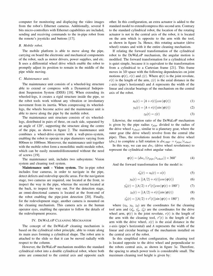
other. In this configuration, an extra actuator is added to thestandard model to extend/compress this second arm. Contraryto the standard cylindrical robot, the location of the rotatingactuator is not in the central axis of the robot, it is locatedon the arm which is opposite to the arm with the tool,as shown in figure 3a. Hence, this rotating actuator (drivewheel) rotates and with it the entire cleaning mechanism.
If relating the forward transformation of the cylindricalrobot to the DeWaLoP mechanism, the angular motion ismodified. The forward transformation for a cylindrical robotis quiet simple, because it is equivalent to the transformationfrom a cylindrical to a Cartesian frame [21]. This framemoves in 3D space with the following dependencies on jointmotions ϕ(t), r(t) and z(t). Where ϕ(t) is the joint revolute,r(t) is the length of the arm, z(t) is the axial distance in thez-axis (pipe’s horizontal) and A represents the width of thelinear and circular bearings of the mechanism on the centralaxis of the robot.
x0(t) = [A+ r(t)]cos(ϕ(t)) (1)
y0(t) = [A+ r(t)]sin(ϕ(t)) (2)
z0(t) = z(t) (3)
Likewise, the rotation ratio of the DeWaLoP mechanismis given by the pipe radius rpipe divided to the radius ofthe drive wheel rwheel , similar to a planetary gear, where theouter gear (the drive wheel) revolve from the central (thepipe). Thus, the revolutions needed from the drive wheel(dwr) to complete a full rotation is dwr360◦ = rpipe/rwheel .
In this way, we can use dwr (drive wheel revolutions) torepresent the cylindrical robot angular value.
ϕ(t) = (dwr/(rpipe/rwheel))×360◦ (4)
And the forward transformation for the model is:
x′0(t) = x0(t) = x(t) (5)
y0(t) = [(A/2)+ r(t)]cos(ϕ(t)) (6)
y′0(t) = [(A/2)+ r′(t)]cos(ϕ(t)+180◦) (7)
z0(t) = [(A/2)+ r(t)]sin(ϕ(t)) (8)
z′0(t) = [(A/2)+ r′(t)]sin(ϕ(t)+180◦) (9)
where (x0, y0, z0) are the coordinates for the cleaningtool arm and (x′0, y′0, z′0) are the coordinates for the drivewheel arm, ϕ(t) is the joint revolute, r(t) is the length ofthe arm with the cleaning tool, r′(t) is the length of thearm with the drive wheel, x(t) is the axial distance in thex-axis (pipe’s horizontal) and A represents the width of thelinear and circular bearings of the mechanism installed onthe central axis of the robot.
In this simplified robot configuration, the cleaning toolis located opposite to the drive wheel and perpendicular tothe robots central axis, as shown in figure 3a. Therefore,the spacing to attach power tools is considerable small. Themaximum cleaning tool height is given by:
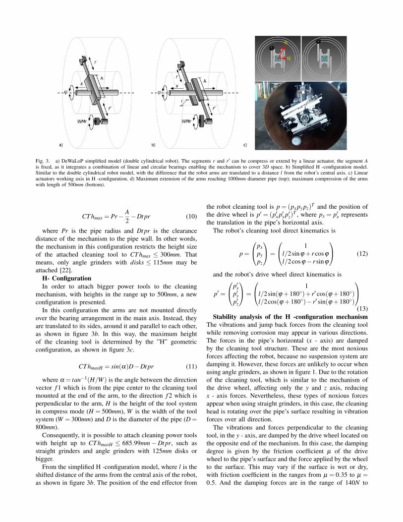
Fig. 3. a) DeWaLoP simplified model (double cylindrical robot). The segments r and r′ can be compress or extend by a linear actuator, the segment Ais fixed, as it integrates a combination of linear and circular bearings enabling the mechanism to cover 3D space. b) Simplified H -configuration model.Similar to the double cylindrical robot model, with the difference that the robot arms are translated to a distance l from the robot’s central axis. c) Linearactuators working axis in H -configuration. d) Maximum extension of the arms reaching 1000mm diameter pipe (top); maximum compression of the armswith length of 500mm (bottom).
CT hmax = Pr− A2−Dt pr (10)
where Pr is the pipe radius and Dt pr is the clearancedistance of the mechanism to the pipe wall. In other words,the mechanism in this configuration restricts the height sizeof the attached cleaning tool to CT hmax ≤ 300mm. Thatmeans, only angle grinders with disks ≤ 115mm may beattached [22].
H- ConfigurationIn order to attach bigger power tools to the cleaning
mechanism, with heights in the range up to 500mm, a newconfiguration is presented.
In this configuration the arms are not mounted directlyover the bearing arrangement in the main axis. Instead, theyare translated to its sides, around it and parallel to each other,as shown in figure 3b. In this way, the maximum heightof the cleaning tool is determined by the ”H” geometricconfiguration, as shown in figure 3c.
CT hmaxH = sin(α)D−Dt pr (11)
where α = tan−1(H/W ) is the angle between the directionvector f 1 which is from the pipe center to the cleaning toolmounted at the end of the arm, to the direction f 2 which isperpendicular to the arm, H is the height of the tool systemin compress mode (H = 500mm), W is the width of the toolsystem (W = 300mm) and D is the diameter of the pipe (D =800mm).
Consequently, it is possible to attach cleaning power toolswith height up to CT hmaxH ≤ 685.99mm−Dt pr, such asstraight grinders and angle grinders with 125mm disks orbigger.
From the simplified H -configuration model, where l is theshifted distance of the arms from the central axis of the robot,as shown in figure 3b. The position of the end effector from
the robot cleaning tool is p = (px py pz)T and the position of
the drive wheel is p′ = (p′x p′y p′z)T , where px = p′x represents
the translation in the pipe’s horizontal axis.The robot’s cleaning tool direct kinematics is
p =
pxpypz
=
1l/2sinϕ + r cosϕ
l/2cosϕ− r sinϕ
(12)
and the robot’s drive wheel direct kinematics is
p′ =
p′xp′yp′z
=
1l/2sin(ϕ +180◦)+ r′ cos(ϕ +180◦)l/2cos(ϕ +180◦)− r′ sin(ϕ +180◦)
(13)
Stability analysis of the H -configuration mechanismThe vibrations and jump back forces from the cleaning toolwhile removing corrosion may appear in various directions.The forces in the pipe’s horizontal (x - axis) are dampedby the cleaning tool structure. These are the most noxiousforces affecting the robot, because no suspension system aredamping it. However, these forces are unlikely to occur whenusing angle grinders, as shown in figure 1. Due to the rotationof the cleaning tool, which is similar to the mechanism ofthe drive wheel, affecting only the y and z axis, reducingx - axis forces. Nevertheless, these types of noxious forcesappear when using straight grinders, in this case, the cleaninghead is rotating over the pipe’s surface resulting in vibrationforces over all direction.
The vibrations and forces perpendicular to the cleaningtool, in the y - axis, are damped by the drive wheel located onthe opposite end of the mechanism. In this case, the dampingdegree is given by the friction coefficient µ of the drivewheel to the pipe’s surface and the force applied by the wheelto the surface. This may vary if the surface is wet or dry,with friction coefficient in the ranges from µ = 0.35 to µ =0.5. And the damping forces are in the range of 140N to
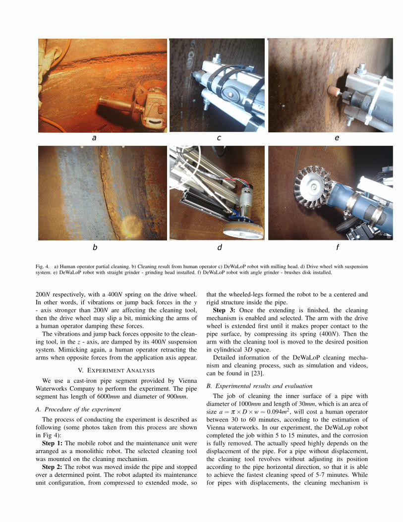
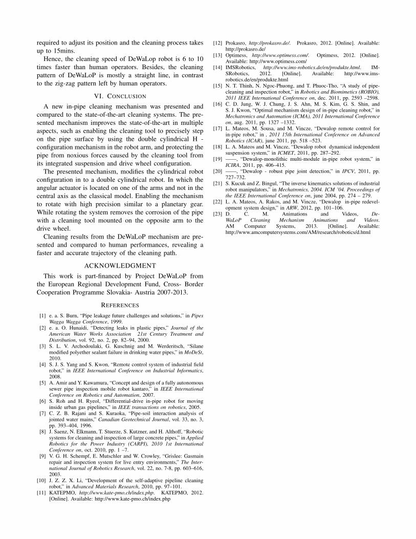
Fig. 4. a) Human operator partial cleaning. b) Cleaning result from human operator c) DeWaLoP robot with milling head. d) Drive wheel with suspensionsystem. e) DeWaLoP robot with straight grinder - grinding head installed. f) DeWaLoP robot with angle grinder - brushes disk installed.
200N respectively, with a 400N spring on the drive wheel.In other words, if vibrations or jump back forces in the y- axis stronger than 200N are affecting the cleaning tool,then the drive wheel may slip a bit, mimicking the arms ofa human operator damping these forces.
The vibrations and jump back forces opposite to the clean-ing tool, in the z - axis, are damped by its 400N suspensionsystem. Mimicking again, a human operator retracting thearms when opposite forces from the application axis appear.
V. EXPERIMENT ANALYSIS
We use a cast-iron pipe segment provided by ViennaWaterworks Company to perform the experiment. The pipesegment has length of 6000mm and diameter of 900mm.
A. Procedure of the experiment
The process of conducting the experiment is described asfollowing (some photos taken from this process are shownin Fig 4):
Step 1: The mobile robot and the maintenance unit werearranged as a monolithic robot. The selected cleaning toolwas mounted on the cleaning mechanism.
Step 2: The robot was moved inside the pipe and stoppedover a determined point. The robot adapted its maintenanceunit configuration, from compressed to extended mode, so
that the wheeled-legs formed the robot to be a centered andrigid structure inside the pipe.
Step 3: Once the extending is finished, the cleaningmechanism is enabled and selected. The arm with the drivewheel is extended first until it makes proper contact to thepipe surface, by compressing its spring (400N). Then thearm with the cleaning tool is moved to the desired positionin cylindrical 3D space.
Detailed information of the DeWaLoP cleaning mecha-nism and cleaning process, such as simulation and videos,can be found in [23].
B. Experimental results and evaluation
The job of cleaning the inner surface of a pipe withdiameter of 1000mm and length of 30mm, which is an area ofsize a = π ×D×w = 0.094m2, will cost a human operatorbetween 30 to 60 minutes, according to the estimation ofVienna waterworks. In our experiment, the DeWaLop robotcompleted the job within 5 to 15 minutes, and the corrosionis fully removed. The actually speed highly depends on thedisplacement of the pipe. For a pipe without displacement,the cleaning tool revolves without adjusting its positionaccording to the pipe horizontal direction, so that it is ableto achieve the fastest cleaning speed of 5-7 minutes. Whilefor pipes with displacements, the cleaning mechanism is
required to adjust its position and the cleaning process takesup to 15mins.
Hence, the cleaning speed of DeWaLop robot is 6 to 10times faster than human operators. Besides, the cleaningpattern of DeWaLoP is mostly a straight line, in contrastto the zig-zag pattern left by human operators.
VI. CONCLUSION
A new in-pipe cleaning mechanism was presented andcompared to the state-of-the-art cleaning systems. The pre-sented mechanism improves the state-of-the-art in multipleaspects, such as enabling the cleaning tool to precisely stepon the pipe surface by using the double cylindrical H -configuration mechanism in the robot arm, and protecting thepipe from noxious forces caused by the cleaning tool fromits integrated suspension and drive wheel configuration.
The presented mechanism, modifies the cylindrical robotconfiguration in to a double cylindrical robot. In which theangular actuator is located on one of the arms and not in thecentral axis as the classical model. Enabling the mechanismto rotate with high precision similar to a planetary gear.While rotating the system removes the corrosion of the pipewith a cleaning tool mounted on the opposite arm to thedrive wheel.
Cleaning results from the DeWaLoP mechanism are pre-sented and compared to human performances, revealing afaster and accurate trajectory of the cleaning path.
ACKNOWLEDGMENT
This work is part-financed by Project DeWaLoP fromthe European Regional Development Fund, Cross- BorderCooperation Programme Slovakia- Austria 2007-2013.
REFERENCES
[1] e. a. S. Burn, “Pipe leakage future challenges and solutions,” in PipesWagga Wagga Conference, 1999.
[2] e. a. O. Hunaidi, “Detecting leaks in plastic pipes,” Journal of theAmerican Water Works Association 21st Century Treatment andDistribution, vol. 92, no. 2, pp. 82–94, 2000.
[3] S. L. V. Archodoulaki, G. Kuschnig and M. Werderitsch, “Silanemodified polyether sealant failure in drinking water pipes,” in MoDeSt,2010.
[4] S. J. S. Yang and S. Kwon, “Remote control system of industrial fieldrobot,” in IEEE International Conference on Industrial Informatics,2008.
[5] A. Amir and Y. Kawamura, “Concept and design of a fully autonomoussewer pipe inspection mobile robot kantaro,” in IEEE InternationalConference on Robotics and Automation, 2007.
[6] S. Roh and H. Ryeol, “Differential-drive in-pipe robot for movinginside urban gas pipelines,” in IEEE transactions on robotics, 2005.
[7] C. Z. B. Rajani and S. Kuraoka, “Pipe-soil interaction analysis ofjointed water mains,” Canadian Geotechnical Journal, vol. 33, no. 3,pp. 393–404, 1996.
[8] J. Saenz, N. Elkmann, T. Stuerze, S. Kutzner, and H. Althoff, “Roboticsystems for cleaning and inspection of large concrete pipes,” in AppliedRobotics for the Power Industry (CARPI), 2010 1st InternationalConference on, oct. 2010, pp. 1 –7.
[9] V. G. H. Schempf, E. Mutschler and W. Crowley, “Grislee: Gasmainrepair and inspection system for live entry environments,” The Inter-national Journal of Robotics Research, vol. 22, no. 7-8, pp. 603–616,2003.
[10] J. Z. Z. X. Li, “Development of the self-adaptive pipeline cleaningrobot,” in Advanced Materials Research, 2010, pp. 97–101.
[11] KATEPMO, http://www.kate-pmo.ch/index.php. KATEPMO, 2012.[Online]. Available: http://www.kate-pmo.ch/index.php
[12] Prokasro, http://prokasro.de/. Prokasro, 2012. [Online]. Available:http://prokasro.de/
[13] Optimess, http://www.optimess.com/. Optimess, 2012. [Online].Available: http://www.optimess.com/
[14] IMSRobotics, http://www.ims-robotics.de/en/produkte.html. IM-SRobotics, 2012. [Online]. Available: http://www.ims-robotics.de/en/produkte.html
[15] N. T. Thinh, N. Ngoc-Phuong, and T. Phuoc-Tho, “A study of pipe-cleaning and inspection robot,” in Robotics and Biomimetics (ROBIO),2011 IEEE International Conference on, dec. 2011, pp. 2593 –2598.
[16] C. D. Jung, W. J. Chung, J. S. Ahn, M. S. Kim, G. S. Shin, andS. J. Kwon, “Optimal mechanism design of in-pipe cleaning robot,” inMechatronics and Automation (ICMA), 2011 International Conferenceon, aug. 2011, pp. 1327 –1332.
[17] L. Mateos, M. Sousa, and M. Vincze, “Dewalop remote control forin-pipe robot,” in , 2011 15th International Conference on AdvancedRobotics (ICAR), june 2011, pp. 518 –523.
[18] L. A. Mateos and M. Vincze, “Dewalop robot dynamical independentsuspension system,” in ICMET, 2011, pp. 287–292.
[19] ——, “Dewalop-monolithic multi-module in-pipe robot system,” inICIRA, 2011, pp. 406–415.
[20] ——, “Dewalop - robust pipe joint detection,” in IPCV, 2011, pp.727–732.
[21] S. Kucuk and Z. Bingul, “The inverse kinematics solutions of industrialrobot manipulators,” in Mechatronics, 2004. ICM ’04. Proceedings ofthe IEEE International Conference on, june 2004, pp. 274 – 279.
[22] L. A. Mateos, A. Rakos, and M. Vincze, “Dewalop in-pipe redevel-opment system design,” in ARW, 2012, pp. 101–106.
[23] D. C. M. Animations and Videos, De-WaLoP Cleaning Mechanism Animations and Videos.AM Computer Systems, 2013. [Online]. Available:http://www.amcomputersystems.com/AM/research/robotics/d.html