cl-7 control panel retrofit installation instructions - eaton€¦ · cl-7 control panel retrofit...
TRANSCRIPT
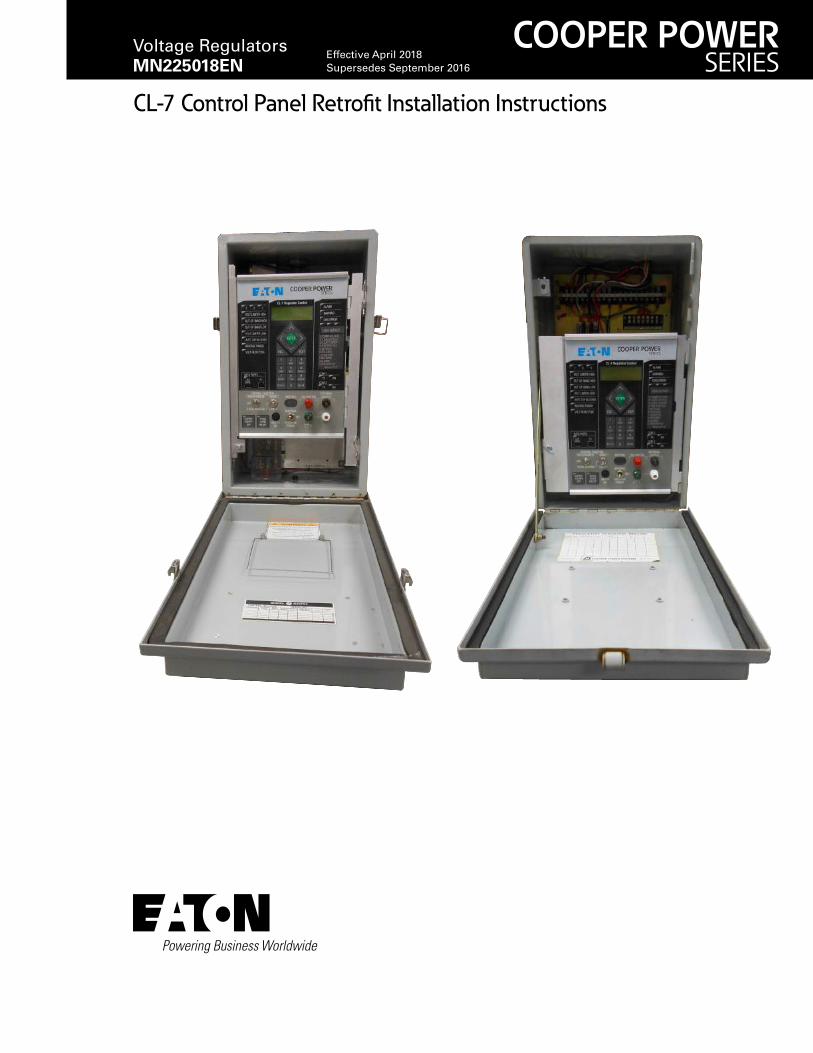
CL-7 Control Panel Retrofit Installation Instructions
COOPER POWERSERIES
Voltage Regulators MN225018EN
Effective April 2018Supersedes September 2016
DISCLAIMER OF WARRANTIES AND LIMITATION OF LIABILITY
The information, recommendations, descriptions and safety notations in this document are based on Eaton Corporation’s (“Eaton”) experience and judgment and may not cover all contingencies. If further information is required, an Eaton sales office should be consulted. Sale of the product shown in this literature is subject to the terms and conditions outlined in appropriate Eaton selling policies or other contractual agreement between Eaton and the purchaser.
THERE ARE NO UNDERSTANDINGS, AGREEMENTS, WARRANTIES, EXPRESSED OR IMPLIED, INCLUDING WARRANTIES OF FITNESS FOR A PARTICULAR PURPOSE OR MERCHANTABILITY, OTHER THAN THOSE SPECIFICALLY SET OUT IN ANY EXISTING CONTRACT BETWEEN THE PARTIES. ANY SUCH CONTRACT STATES THE ENTIRE OBLIGATION OF EATON. THE CONTENTS OF THIS DOCUMENT SHALL NOT BECOME PART OF OR MODIFY ANY CONTRACT BETWEEN THE PARTIES.
In no event will Eaton be responsible to the purchaser or user in contract, in tort (including negligence), strict liability or otherwise for any special, indirect, incidental or consequential damage or loss whatsoever, including but not limited to damage or loss of use of equipment, plant or power system, cost of capital, loss of power, additional expenses in the use of existing power facilities, or claims against the purchaser or user by its customers resulting from the use of the information, recommendations and descriptions contained herein. The information contained in this manual is subject to change without notice.
ii InstallatIon InstructIons MN225018EN April 2018
Contents
DISCLAIMER OF WARRANTIES AND LIMITATION OF LIABILITY . . . . . . . . . . . . . . . . . . . . . . . . . . . . . . . . . . . II
SAFETY FOR LIFE . . . . . . . . . . . . . . . . . . . . . . . . . . . . . . . . . . . . . . . . . . . . . . . . . . . . . . . . . . . . . . . . . . . . . . . . . IV
SAFETY INFORMATION . . . . . . . . . . . . . . . . . . . . . . . . . . . . . . . . . . . . . . . . . . . . . . . . . . . . . . . . . . . . . . . . . . . . IVSafety instructions . . . . . . . . . . . . . . . . . . . . . . . . . . . . . . . . . . . . . . . . . . . . . . . . . . . . . . . . . . . . . . . . . . . . . . . . . . . . . . iv
PRODUCT INFORMATION . . . . . . . . . . . . . . . . . . . . . . . . . . . . . . . . . . . . . . . . . . . . . . . . . . . . . . . . . . . . . . . . . . . 1Introduction . . . . . . . . . . . . . . . . . . . . . . . . . . . . . . . . . . . . . . . . . . . . . . . . . . . . . . . . . . . . . . . . . . . . . . . . . . . . . . . . . . . .1
Read this manual first . . . . . . . . . . . . . . . . . . . . . . . . . . . . . . . . . . . . . . . . . . . . . . . . . . . . . . . . . . . . . . . . . . . . . . . . . . .1
Additional information . . . . . . . . . . . . . . . . . . . . . . . . . . . . . . . . . . . . . . . . . . . . . . . . . . . . . . . . . . . . . . . . . . . . . . . . . . . .1
Acceptance and initial inspection . . . . . . . . . . . . . . . . . . . . . . . . . . . . . . . . . . . . . . . . . . . . . . . . . . . . . . . . . . . . . . . . . . .1
Handling and storage . . . . . . . . . . . . . . . . . . . . . . . . . . . . . . . . . . . . . . . . . . . . . . . . . . . . . . . . . . . . . . . . . . . . . . . . . . . .1
Quality standards. . . . . . . . . . . . . . . . . . . . . . . . . . . . . . . . . . . . . . . . . . . . . . . . . . . . . . . . . . . . . . . . . . . . . . . . . . . . . . . .1
CL-7 CONTROL IN EATON CONTROL BOX, DEAD FRONT . . . . . . . . . . . . . . . . . . . . . . . . . . . . . . . . . . . . . . . . . 2Required tools . . . . . . . . . . . . . . . . . . . . . . . . . . . . . . . . . . . . . . . . . . . . . . . . . . . . . . . . . . . . . . . . . . . . . . . . . . . . . . . . . .2
Installation procedure . . . . . . . . . . . . . . . . . . . . . . . . . . . . . . . . . . . . . . . . . . . . . . . . . . . . . . . . . . . . . . . . . . . . . . . . . . . .2
CL-7 CONTROL IN EATON CONTROL BOX, NOT DEAD FRONT . . . . . . . . . . . . . . . . . . . . . . . . . . . . . . . . . . . . 4Required tools . . . . . . . . . . . . . . . . . . . . . . . . . . . . . . . . . . . . . . . . . . . . . . . . . . . . . . . . . . . . . . . . . . . . . . . . . . . . . . . . . .4
Installation procedure . . . . . . . . . . . . . . . . . . . . . . . . . . . . . . . . . . . . . . . . . . . . . . . . . . . . . . . . . . . . . . . . . . . . . . . . . . . .4
CL-7 CONTROL IN SIEMENS CORPORATION CONTROL BOX . . . . . . . . . . . . . . . . . . . . . . . . . . . . . . . . . . . . . 7Required tools . . . . . . . . . . . . . . . . . . . . . . . . . . . . . . . . . . . . . . . . . . . . . . . . . . . . . . . . . . . . . . . . . . . . . . . . . . . . . . . . . .7
Installation procedure . . . . . . . . . . . . . . . . . . . . . . . . . . . . . . . . . . . . . . . . . . . . . . . . . . . . . . . . . . . . . . . . . . . . . . . . . . . .7
CL-7 CONTROL IN GENERAL ELECTRIC CONTROL BOX WITH FORK-TYPE TERMINAL . . . . . . . . . . . . . . . . .10Required tools . . . . . . . . . . . . . . . . . . . . . . . . . . . . . . . . . . . . . . . . . . . . . . . . . . . . . . . . . . . . . . . . . . . . . . . . . . . . . . . . .10
Installation procedure . . . . . . . . . . . . . . . . . . . . . . . . . . . . . . . . . . . . . . . . . . . . . . . . . . . . . . . . . . . . . . . . . . . . . . . . . . .10
CL-7 CONTROL IN GENERAL ELECTRIC CONTROL BOX WITH PIN-TYPE TERMINAL . . . . . . . . . . . . . . . . . 13Required tools . . . . . . . . . . . . . . . . . . . . . . . . . . . . . . . . . . . . . . . . . . . . . . . . . . . . . . . . . . . . . . . . . . . . . . . . . . . . . . . . .13
Installation procedure . . . . . . . . . . . . . . . . . . . . . . . . . . . . . . . . . . . . . . . . . . . . . . . . . . . . . . . . . . . . . . . . . . . . . . . . . . .13
CL-7 CONTROL IN HOWARD INDUSTRIES CONTROL BOX . . . . . . . . . . . . . . . . . . . . . . . . . . . . . . . . . . . . . . . 16Required tools . . . . . . . . . . . . . . . . . . . . . . . . . . . . . . . . . . . . . . . . . . . . . . . . . . . . . . . . . . . . . . . . . . . . . . . . . . . . . . . . .16
Installation procedure . . . . . . . . . . . . . . . . . . . . . . . . . . . . . . . . . . . . . . . . . . . . . . . . . . . . . . . . . . . . . . . . . . . . . . . . . . .16
iiiInstallatIon InstructIons MN225018EN April 2018

Safety for life
Eaton meets or exceeds all applicable industry standards relating to product safety in its Cooper Power™ series products. We actively promote safe practices in the use and maintenance of our products through our service literature, instructional training programs, and the continuous efforts of all Eaton employees involved in product design, manufacture, marketing, and service.
We strongly urge that you always follow all locally-approved safety procedures and safety instructions when working around high-voltage lines and equipment, and support our “Safety For Life” mission.
Safety information
The instructions in this manual are not intended as a substitute for proper training or adequate experience in the safe operation of the equipment described. Only competent technicians who are familiar with this equipment should install, operate, and service it.
A competent technician has these qualifications:
●● Is thoroughly familiar with these instructions.
●● Is trained in industry-accepted high- and low-voltage safe operating practices and procedures.
●● Is trained and authorized to energize, de-energize, clear, and ground power distribution equipment.
●● Is trained in the care and use of protective equipment such as arc flash clothing, safety glasses, face shield, hard hat, rubber gloves, clampstick, hotstick, etc.
Following is important safety information. For safe installation and operation of this equipment, be sure to read and understand all cautions and warnings.
Hazard Statement DefinitionsThis manual may contain four types of hazard statements:
DANGERIndicates an imminently hazardous situation which, if not avoided, will result in death or serious injury .
WARNINGIndicates a potentially hazardous situation which, if not avoided, could result in death or serious injury .
CAUTIONIndicates a potentially hazardous situation which, if not avoided, may result in minor or moderate injury .
NOTICEIndicates a potentially hazardous situation which, if not avoided, may result in equipment damage only .
Safety instructionsFollowing are general caution and warning statements that apply to this equipment. Additional statements, related to specific tasks and procedures, are located throughout the manual.
DANGERHazardous voltage . Contact with hazardous voltage will cause death or severe personal injury . Follow all locally-approved safety procedures when working around high- and low-voltage lines and equipment . G103 .3
WARNINGBefore installing, operating, maintaining, or testing this equipment, carefully read and understand the contents of this manual . Improper operation, handling, or maintenance can result in death, severe personal injury, and equipment damage . G101 .0
WARNINGThis equipment is not intended to protect human life . Follow all locally-approved procedures and safety practices when installing or operating this equipment . Failure to comply can result in death, severe personal injury, and equipment damage . G102 .1
WARNINGPower distribution and transmission equipment must be properly selected for the intended application . It must be installed and serviced by competent personnel who have been trained and understand proper safety procedures . These instructions are written for such personnel and are not a substitute for adequate training and experience in safety procedures . Failure to properly select, install, or maintain power distribution and transmission equipment can result in death, severe personal injury, and equipment damage . G122 .2
!SAFETYFOR LIFE
!SAFETYFOR LIFE
iv
CL-7 Control Panel Retrofit
InstallatIon InstructIons MN225018EN April 2018
Product information
IntroductionThis document provides the instructions for retrofitting an Eaton‘s Cooper Power™ series CL-7 control panel on an Eaton, Siemens Corporation, General Electric, or Howard Industries, Inc. 32-step voltage regulator.
Read this manual first Read and understand the contents of this manual and follow all locally approved procedures and safety practices before installing or operating this equipment. Read and understand the manuals detailing the installation and operation of the regulator and the regulator control used with the regulator. Refer to document MN225003EN, CL-7 Voltage Regulator Control Installation, Operation, and Maintenance Instructions for information on the CL-7 voltage regulator control. Refer to document MN225008EN, VR-32 Voltage Regulator with Quik-Drive™ Tap-Changer Installation, Operation, and Maintenance Instructions for information on Eaton‘s voltage regulator with Quik-Drive tap-changer.
Additional information These instructions cannot cover all details or variations in the equipment, procedures, or process described nor provide directions for meeting every possible contingency during installation, operation, or maintenance. For additional information, please contact your Eaton representative.
Acceptance and initial inspection This kit is thoroughly inspected at the factory. It is in good condition when accepted by the carrier for shipment.
Upon receipt of the regulator kit, a thorough inspection should be made for damage, evidence of rough handling, or shortages. Should this initial inspection reveal evidence of rough handling, damage, or shortages, it should be noted on the bill of lading and a claim should immediately be made with the carrier. Also, notify your Eaton representative.
Handling and storage Be careful during handing and storage of equipment to minimize the possibility of damage. If the regulator kit is not to be placed into immediate use, store the kit where the possibility of damage is minimized.
Quality standardsISO 9001 Certified Quality Management System
1
CL-7 Control Panel Retrofit
InstallatIon InstructIons MN225018EN April 2018
CL-7 control in Eaton control box, dead front
Table 1 . Kit parts identification
Item Description Part Number Qty
1 Jumper, 7 terminals width A613078004 12 Backpanel tool, plastic* A613098002 1*Retain for future use.
otee:N Eaton‘s Universal PRA kit may include parts not required for every installation. Only parts required for this installation are included in this list.
Required tools●● Screwdriver (Phillips)
●● Backpanel tool (included in kit)
otee:N Verify all kit items are present before beginning installation procedure.
Installation procedureFollow these instructions to install the CL-7 control in a control box on an Eaton‘s Cooper Power series voltage regulator with a dead-front backpanel.
1. Remove the existing control:
●● Refer to the appropriate voltage regulator control manual for complete instructions on removing a control.
●● Refer to document MN225016EN, VR-32 Voltage Regulators CL-6 Series Control Installation, Operation, and Maintenance Instructions for information on the Eaton‘s Cooper Power series CL-6 series voltage regulator control.
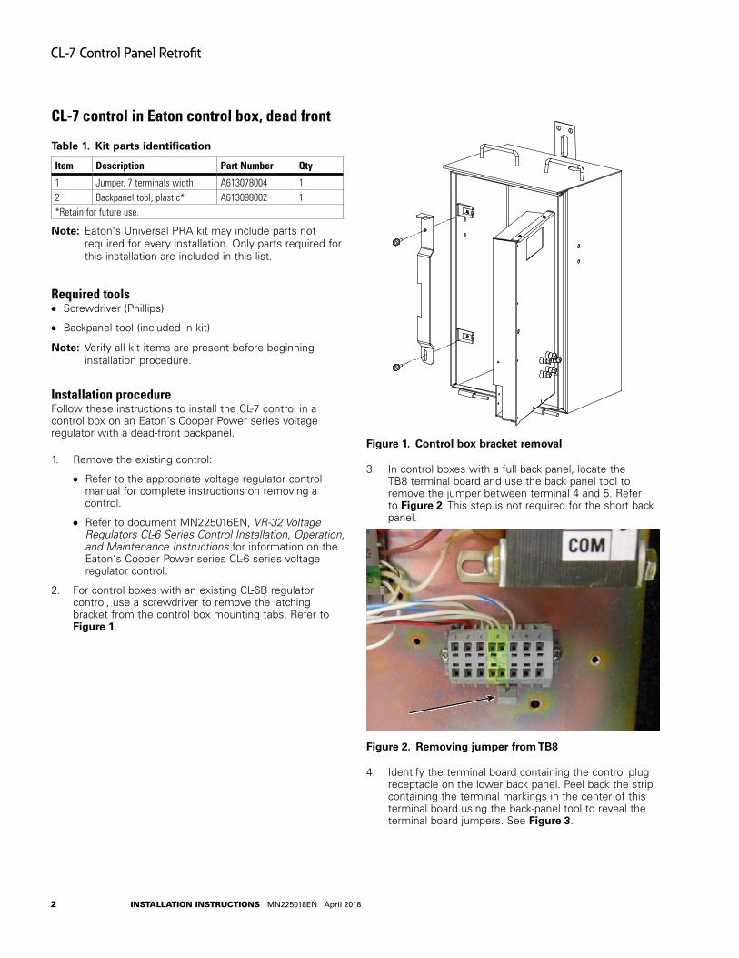
2. For control boxes with an existing CL-6B regulator control, use a screwdriver to remove the latching bracket from the control box mounting tabs. Refer to Figure 1.
Figure 1 . Control box bracket removal
3. In control boxes with a full back panel, locate the TB8 terminal board and use the back panel tool to remove the jumper between terminal 4 and 5. Refer to Figure 2. This step is not required for the short back panel.
Figure 2 . Removing jumper from TB8
4. Identify the terminal board containing the control plug receptacle on the lower back panel. Peel back the strip containing the terminal markings in the center of this terminal board using the back-panel tool to reveal the terminal board jumpers. See Figure 3.
2
CL-7 Control Panel Retrofit
InstallatIon InstructIons MN225018EN April 2018
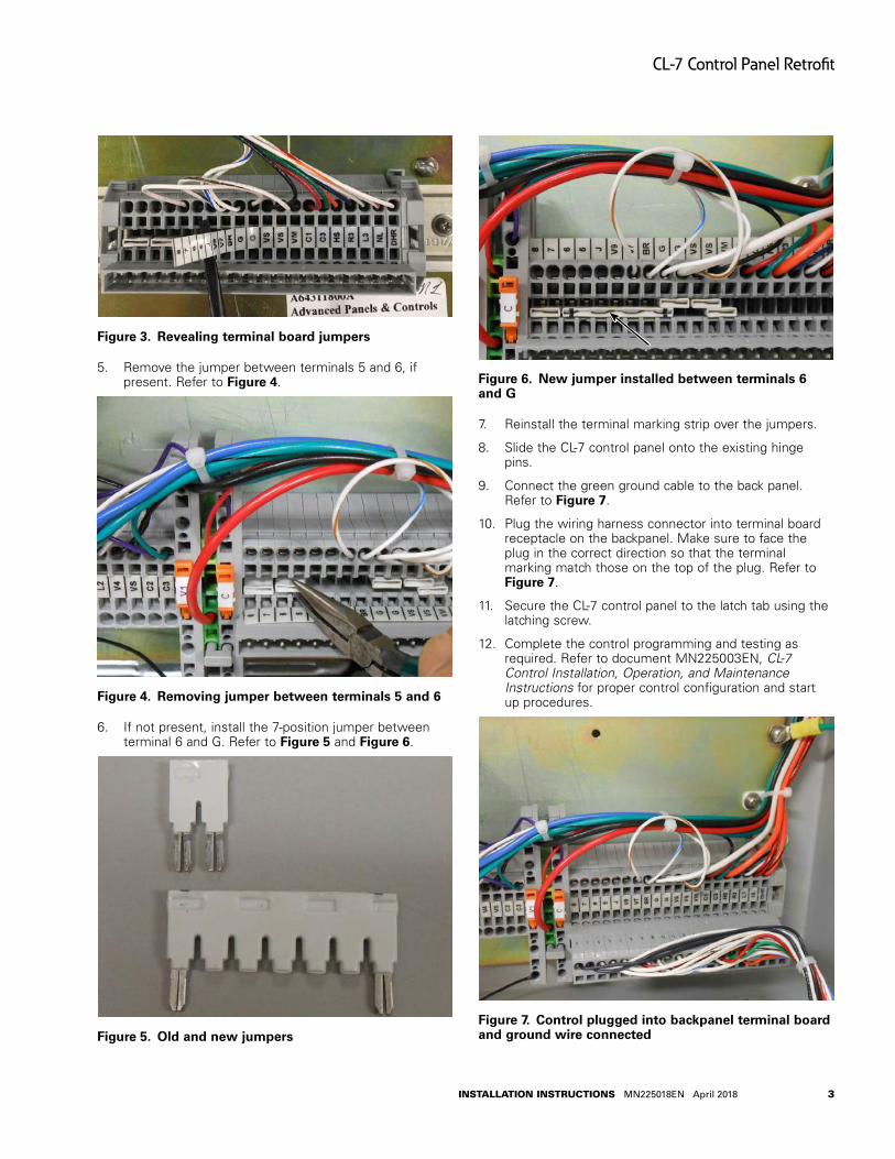
Figure 3 . Revealing terminal board jumpers
5. Remove the jumper between terminals 5 and 6, if present. Refer to Figure 4.
Figure 4 . Removing jumper between terminals 5 and 6
6. If not present, install the 7-position jumper between terminal 6 and G. Refer to Figure 5 and Figure 6.
Figure 5 . Old and new jumpers
Figure 6 . New jumper installed between terminals 6 and G
7. Reinstall the terminal marking strip over the jumpers.
8. Slide the CL-7 control panel onto the existing hinge pins.
9. Connect the green ground cable to the back panel. Refer to Figure 7.
10. Plug the wiring harness connector into terminal board receptacle on the backpanel. Make sure to face the plug in the correct direction so that the terminal marking match those on the top of the plug. Refer to Figure 7.
11. Secure the CL-7 control panel to the latch tab using the latching screw.
12. Complete the control programming and testing as required. Refer to document MN225003EN, CL-7 Control Installation, Operation, and Maintenance Instructions for proper control configuration and start up procedures.
Figure 7 . Control plugged into backpanel terminal board and ground wire connected
3
CL-7 Control Panel Retrofit
InstallatIon InstructIons MN225018EN April 2018

CL-7 control in Eaton control box, not dead front
Table 2 . Kit parts identification
Item Description Part Number Qty
1 Wiring harness assembly, Fanning strip style
A64316200E 1
2 18-position terminal board kit A64289100B 13 Terminal jumper TAA114731001 24 Jumper wire 102A008HEHE043 1
otee:N Eaton‘s Universal PRA kit may include parts not required for every installation. Only parts required for this installation are included in this list.
Required tools●● Screwdriver (Standard)
●● Screwdriver (Phillips)
otee:N Verify all kit items are present before beginning installation procedure.
Installation procedureFollow these instructions to install the CL-7 PRA into a control box on an Eaton voltage regulator with a fanning strip terminal board connection.
1. Remove the existing control. Refer to the appropriate voltage regulator control manual for complete instructions on removing a control.
For example, refer to Service Information S225-10-10, McGraw-Edison® VR-32 Regulator and CL-5 Series Control Installation, Operation and Maintenance Instructions for information on the CL-5 series voltage regulator control.
2. If the control box contains a 10-position TB1 terminal board (see Figure 8), it must be upgraded to an 18-position board. See document MN225019EN, Back Panel Upgrade 10- to 18-Position Terminal Strip Installation Instructions for instruction on installing the 18-position terminal board.
Figure 8 . Obsolete 10-position terminal board to be replaced
3. If the control box is already equipped with the 18-position terminal board, it must be reconfigured to the correct jumper configuration. A metal jumper is required between terminal 3 and 4 and a wire jumper is required between terminals 2 and G (see Figure 9).
Figure 9 . Proper jumper arrangement on 18-position terminal board for the CL-7 voltage regulator control
4. If a jumper is present between terminals 4 and 5 of TB8 (see Figure 10), remove the jumper. If this jumper remains in place, the CL-7 control will display an Auto Tap Blocked indication.
Figure 10 . Remove metal jumper between terminals 4 and 5
4
CL-7 Control Panel Retrofit
InstallatIon InstructIons MN225018EN April 2018
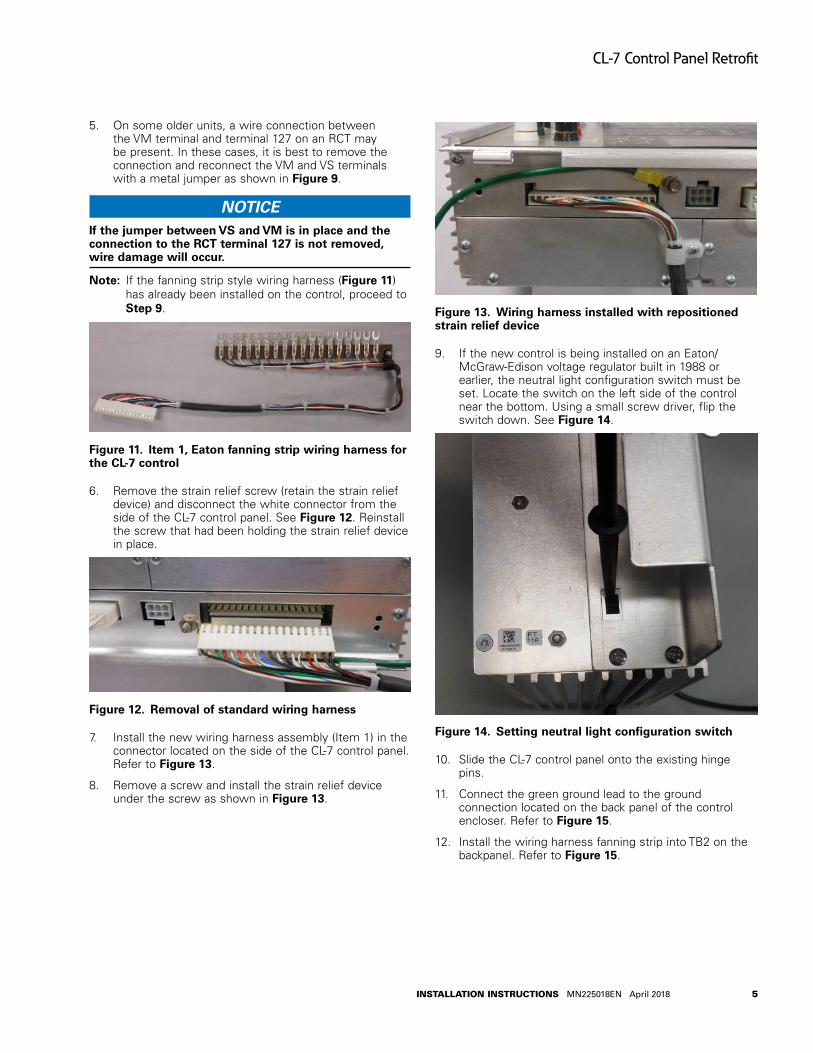
5. On some older units, a wire connection between the VM terminal and terminal 127 on an RCT may be present. In these cases, it is best to remove the connection and reconnect the VM and VS terminals with a metal jumper as shown in Figure 9.
NOTICEIf the jumper between VS and VM is in place and the connection to the RCT terminal 127 is not removed, wire damage will occur .
otee:N If the fanning strip style wiring harness (Figure 11) has already been installed on the control, proceed to Step 9.
Figure 11 . Item 1, Eaton fanning strip wiring harness for the CL-7 control
6. Remove the strain relief screw (retain the strain relief device) and disconnect the white connector from the side of the CL-7 control panel. See Figure 12. Reinstall the screw that had been holding the strain relief device in place.
Figure 12 . Removal of standard wiring harness
7. Install the new wiring harness assembly (Item 1) in the connector located on the side of the CL-7 control panel. Refer to Figure 13.
8. Remove a screw and install the strain relief device under the screw as shown in Figure 13.
Figure 13 . Wiring harness installed with repositioned strain relief device
9. If the new control is being installed on an Eaton/McGraw-Edison voltage regulator built in 1988 or earlier, the neutral light configuration switch must be set. Locate the switch on the left side of the control near the bottom. Using a small screw driver, flip the switch down. See Figure 14.
Figure 14 . Setting neutral light configuration switch
10. Slide the CL-7 control panel onto the existing hinge pins.
11. Connect the green ground lead to the ground connection located on the back panel of the control encloser. Refer to Figure 15.
12. Install the wiring harness fanning strip into TB2 on the backpanel. Refer to Figure 15.
5
CL-7 Control Panel Retrofit
InstallatIon InstructIons MN225018EN April 2018
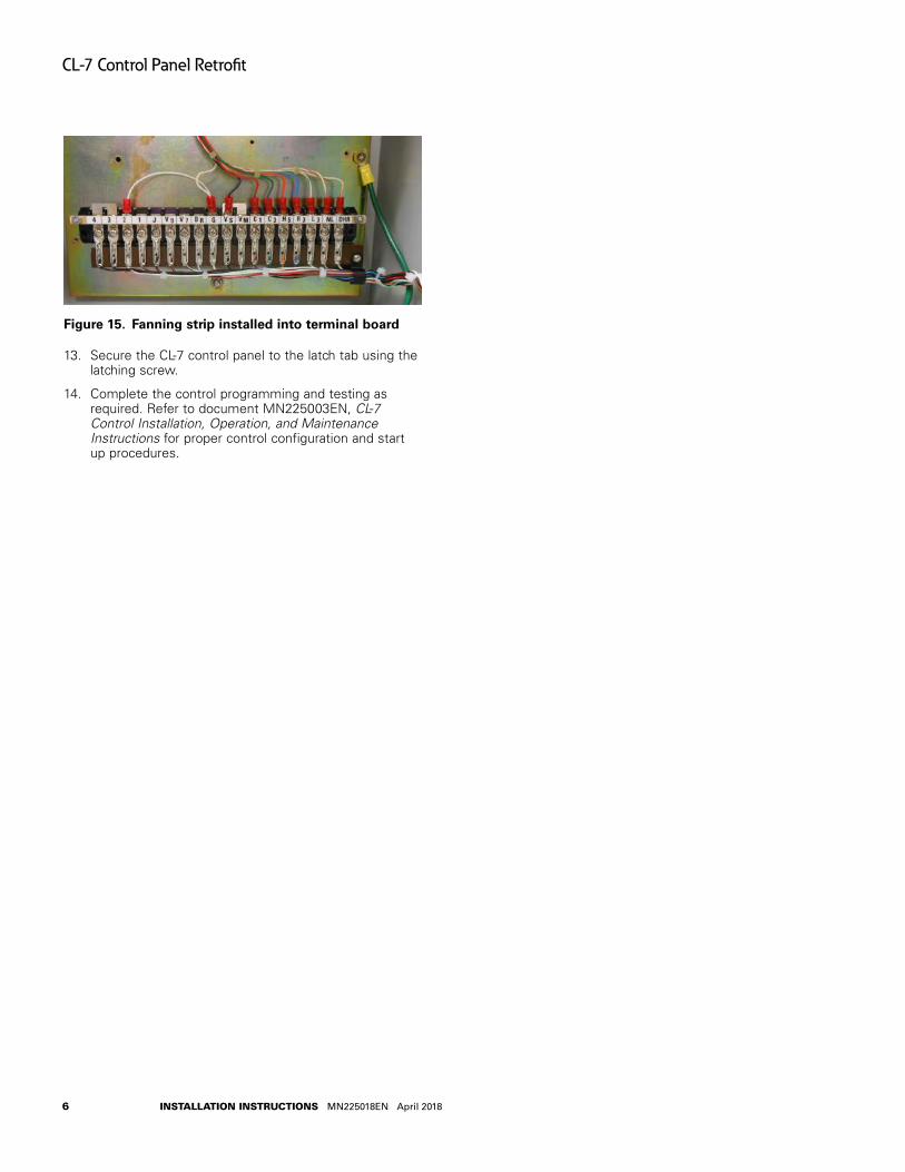
Figure 15 . Fanning strip installed into terminal board
13. Secure the CL-7 control panel to the latch tab using the latching screw.
14. Complete the control programming and testing as required. Refer to document MN225003EN, CL-7 Control Installation, Operation, and Maintenance Instructions for proper control configuration and start up procedures.
6
CL-7 Control Panel Retrofit
InstallatIon InstructIons MN225018EN April 2018
CL-7 control in Siemens Corporation control box
Table 3 . Kit parts identification
Item Description Part Number Qty
1 CL-7 PRA wiring harness, Siemens/Howard control
A64316200F 1
2 Faceplate, Right E0003X00G29 13 Left Hinge Bracket E0003X00G32 1
4 Siemens Retro Kit Magnet Assembly
57A643282002 1
5 Hinge 0800071097Z 26 Machine Screw: 6-32x0.38 0800071090Z 67 Lock Washer: #6 SS 0800070916Z 48 Lock Nut: 6-32 0800071115Z 29 Ground Lead E0003X00G160 110 Adhesive cable-tie anchors 0800069825Z 211 Cable tie 0800011079Z 2
Required tools●● Screwdriver (standard)
●● Screwdriver (Phillips head)
●● 5/16-Inch nut driver or combination wrench
●● 3/8-Inch nut driver or combination wrench
otee:N Verify all kit items are present before beginning installation procedure.
Installation procedureFollow these instructions to install the CL-7 PRA on a voltage regulator manufactured by Siemens Corporation.
1. Remove existing control per manufacturer‘s requirements. Retain the terminal block wing-nuts.
otee:N If the Siemens Corporation style wiring harness (Figure 16), hinge and magnet assemblies (Figure 18) have already been installed on the control, proceed to Step 14.
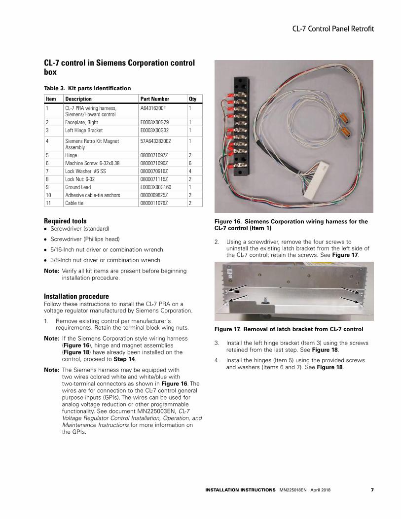
otee:N The Siemens harness may be equipped with two wires colored white and white/blue with two-terminal connectors as shown in Figure 16. The wires are for connection to the CL-7 control general purpose inputs (GPIs). The wires can be used for analog voltage reduction or other programmable functionality. See document MN225003EN, CL-7 Voltage Regulator Control Installation, Operation, and Maintenance Instructions for more information on the GPIs.
Figure 16 . Siemens Corporation wiring harness for the CL-7 control (Item 1)
2. Using a screwdriver, remove the four screws to uninstall the existing latch bracket from the left side of the CL-7 control; retain the screws. See Figure 17.
Figure 17 . Removal of latch bracket from CL-7 control
3. Install the left hinge bracket (Item 3) using the screws retained from the last step. See Figure 18.
4. Install the hinges (Item 5) using the provided screws and washers (Items 6 and 7). See Figure 18.
7
CL-7 Control Panel Retrofit
InstallatIon InstructIons MN225018EN April 2018
2
3
4
5
5
7
6
6
8
6
7
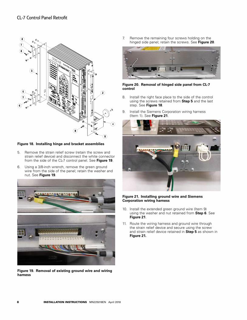
Figure 18 . Installing hinge and bracket assemblies
5. Remove the strain relief screw (retain the screw and strain relief device) and disconnect the white connector from the side of the CL-7 control panel. See Figure 19.
6. Using a 3/8-inch wrench, remove the green ground wire from the side of the panel; retain the washer and nut. See Figure 19.
Figure 19 . Removal of existing ground wire and wiring harness
7. Remove the remaining four screws holding on the hinged side panel; retain the screws. See Figure 20.
Figure 20 . Removal of hinged side panel from CL-7 control
8. Install the right face place to the side of the control using the screws retained from Step 5 and the last step. See Figure 18.
9. Install the Siemens Corporation wiring harness (Item 1). See Figure 21.
Figure 21 . Installing ground wire and Siemens Corporation wiring harness
10. Install the extended green ground wire (Item 9) using the washer and nut retained from Step 6. See Figure 21.
11. Route the wiring harness and ground wire through the strain relief device and secure using the screw and strain relief device retained in Step 5 as shown in Figure 21 .
8
CL-7 Control Panel Retrofit
InstallatIon InstructIons MN225018EN April 2018
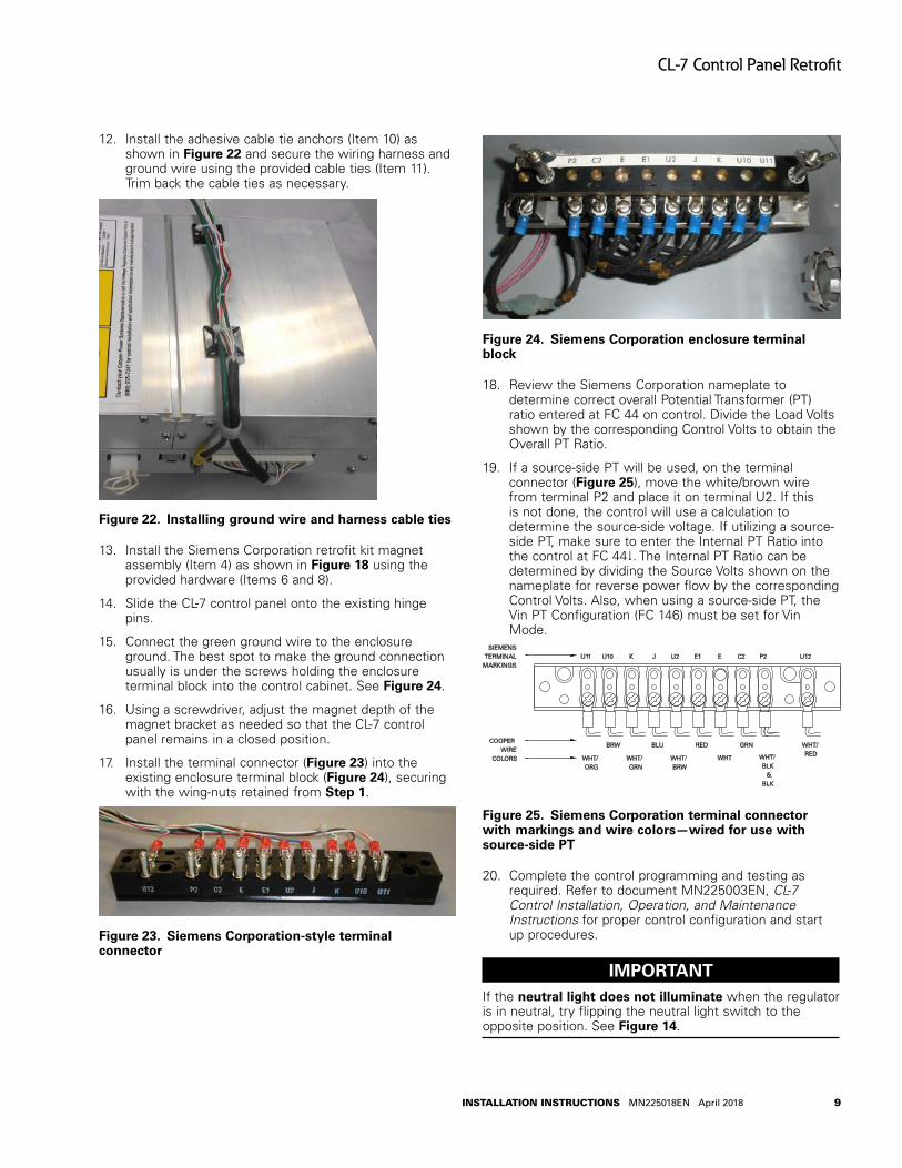
12. Install the adhesive cable tie anchors (Item 10) as shown in Figure 22 and secure the wiring harness and ground wire using the provided cable ties (Item 11). Trim back the cable ties as necessary.
Figure 22 . Installing ground wire and harness cable ties
13. Install the Siemens Corporation retrofit kit magnet assembly (Item 4) as shown in Figure 18 using the provided hardware (Items 6 and 8).
14. Slide the CL-7 control panel onto the existing hinge pins.
15. Connect the green ground wire to the enclosure ground. The best spot to make the ground connection usually is under the screws holding the enclosure terminal block into the control cabinet. See Figure 24.
16. Using a screwdriver, adjust the magnet depth of the magnet bracket as needed so that the CL-7 control panel remains in a closed position.
17. Install the terminal connector (Figure 23) into the existing enclosure terminal block (Figure 24), securing with the wing-nuts retained from Step 1.
Figure 23 . Siemens Corporation-style terminal connector
Figure 24 . Siemens Corporation enclosure terminal block
18. Review the Siemens Corporation nameplate to determine correct overall Potential Transformer (PT) ratio entered at FC 44 on control. Divide the Load Volts shown by the corresponding Control Volts to obtain the Overall PT Ratio.
19. If a source-side PT will be used, on the terminal connector (Figure 25), move the white/brown wire from terminal P2 and place it on terminal U2. If this is not done, the control will use a calculation to determine the source-side voltage. If utilizing a source-side PT, make sure to enter the Internal PT Ratio into the control at FC 44. The Internal PT Ratio can be determined by dividing the Source Volts shown on the nameplate for reverse power flow by the corresponding Control Volts. Also, when using a source-side PT, the Vin PT Configuration (FC 146) must be set for Vin Mode.
U11 U10 K J U2 E1 E C2 P2 U12SIEMENS
TERMINAL MARKINGS
COOPER WIRE
COLORS
WHT/ORG
BRW
WHT/GRN
BLU
WHT/BRW
RED
WHT
GRN
WHT/BLK
& BLK
WHT/RED
Figure 25 . Siemens Corporation terminal connector with markings and wire colors—wired for use with source-side PT
20. Complete the control programming and testing as required. Refer to document MN225003EN, CL-7 Control Installation, Operation, and Maintenance Instructions for proper control configuration and start up procedures.
IMPORTANTIf the neutral light does not illuminate when the regulator is in neutral, try flipping the neutral light switch to the opposite position. See Figure 14.
9
CL-7 Control Panel Retrofit
InstallatIon InstructIons MN225018EN April 2018
CL-7 control in General Electric control box with fork-type terminal
Table 4 . Kit parts identification
Item Description Part Number Qty
1 CL-7 PRA wiring harness, General Electric fork-type terminal
A64316200G 1
2 Hinge bracket assembly E0003X00G22 13 Left side bracket E0003X00G25 1
4 Self adjusting latch E0003X00G158 1
Required tools●● Screwdriver (standard)
●● Screwdriver (Phillips head)
●● 3/8-Inch nut driver or combination wrench
otee:N Verify all kit items are present before beginning installation procedure.
Installation procedureFollow these instructions to install the CL-7 PRA on a voltage regulator manufactured by General Electric with fork-type terminal connections.
1. Remove existing control per the manufacturer‘s requirements. Retain the hinge pins.
otee:N If the General Electric wiring harness (Figure 26), hinge bracket and latch bracket (Figure 28) have already been installed on the new CL-7 control, proceed to Step 11.
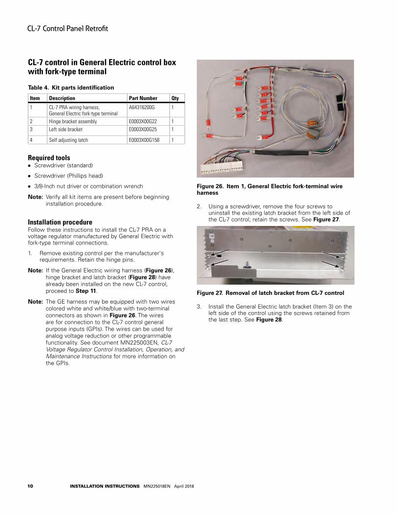
otee:N The GE harness may be equipped with two wires colored white and white/blue with two-terminal connectors as shown in Figure 26. The wires are for connection to the CL-7 control general purpose inputs (GPIs). The wires can be used for analog voltage reduction or other programmable functionality. See document MN225003EN, CL-7 Voltage Regulator Control Installation, Operation, and Maintenance Instructions for more information on the GPIs.
Figure 26 . Item 1, General Electric fork-terminal wire harness
2. Using a screwdriver, remove the four screws to uninstall the existing latch bracket from the left side of the CL-7 control; retain the screws. See Figure 27.
Figure 27 . Removal of latch bracket from CL-7 control
3. Install the General Electric latch bracket (Item 3) on the left side of the control using the screws retained from the last step. See Figure 28.
10
CL-7 Control Panel Retrofit
InstallatIon InstructIons MN225018EN April 2018
3
2
4
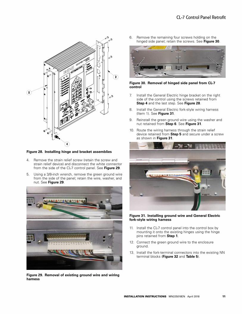
Figure 28 . Installing hinge and bracket assemblies
4. Remove the strain relief screw (retain the screw and strain relief device) and disconnect the white connector from the side of the CL-7 control panel. See Figure 29.
5. Using a 3/8-inch wrench, remove the green ground wire from the side of the panel; retain the wire, washer, and nut. See Figure 29.
Figure 29 . Removal of existing ground wire and wiring harness
6. Remove the remaining four screws holding on the hinged side panel; retain the screws. See Figure 30.
Figure 30 . Removal of hinged side panel from CL-7 control
7. Install the General Electric hinge bracket on the right side of the control using the screws retained from Step 4 and the last step. See Figure 28.
8. Install the General Electric fork-style wiring harness (Item 1). See Figure 31.
9. Reinstall the green ground wire using the washer and nut retained from Step 6. See Figure 31.
10. Route the wiring harness through the strain relief device retained from Step 5 and secure under a screw as shown in Figure 31.
Figure 31 . Installing ground wire and General Electric fork-style wiring harness
11. Install the CL-7 control panel into the control box by mounting it onto the existing hinges using the hinge pins retained from Step 1.
12. Connect the green ground wire to the enclosure ground.
13. Install the fork-terminal connectors into the existing NN terminal blocks (Figure 32 and Table 5).
11
CL-7 Control Panel Retrofit
InstallatIon InstructIons MN225018EN April 2018
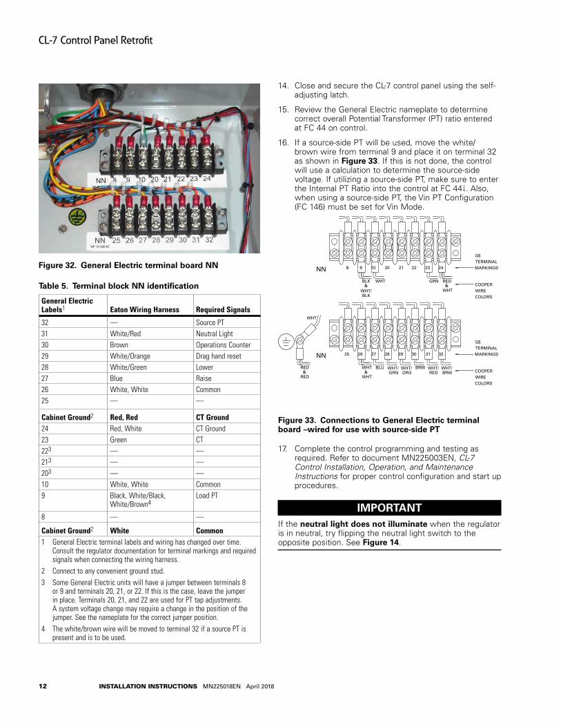
Figure 32 . General Electric terminal board NN
Table 5 . Terminal block NN identification
General Electric Labels1 Eaton Wiring Harness Required Signals
32 — Source PT31 White/Red Neutral Light30 Brown Operations Counter29 White/Orange Drag hand reset28 White/Green Lower27 Blue Raise26 White, White Common25 — —
Cabinet Ground2 Red, Red CT Ground24 Red, White CT Ground23 Green CT223 — —213 — —203 — —10 White, White Common9 Black, White/Black,
White/Brown4Load PT
8 — —
Cabinet Ground2 White Common1 General Electric terminal labels and wiring has changed over time.
Consult the regulator documentation for terminal markings and required signals when connecting the wiring harness.
2 Connect to any convenient ground stud.3 Some General Electric units will have a jumper between terminals 8
or 9 and terminals 20, 21, or 22. If this is the case, leave the jumper in place. Terminals 20, 21, and 22 are used for PT tap adjustments. A system voltage change may require a change in the position of the jumper. See the nameplate for the correct jumper position.
4 The white/brown wire will be moved to terminal 32 if a source PT is present and is to be used.
14. Close and secure the CL-7 control panel using the self-adjusting latch.
15. Review the General Electric nameplate to determine correct overall Potential Transformer (PT) ratio entered at FC 44 on control.
16. If a source-side PT will be used, move the white/brown wire from terminal 9 and place it on terminal 32 as shown in Figure 33. If this is not done, the control will use a calculation to determine the source-side voltage. If utilizing a source-side PT, make sure to enter the Internal PT Ratio into the control at FC 44. Also, when using a source-side PT, the Vin PT Configuration (FC 146) must be set for Vin Mode.
25
COOPER WIRE COLORS
26 27 28 29 30 3231
8 9 10 20 21 22 2423
NN
NN
WHT &
WHT
BLU WHT/GRN
WHT/ORG
BRW WHT/RED
WHT/BRW
BLK &
WHT/BLK
WHT GRN RED&
WHT
GETERMINALMARKINGS
COOPER WIRE COLORS
GETERMINALMARKINGS
RED&
RED
WHT
Figure 33 . Connections to General Electric terminal board –wired for use with source-side PT
17. Complete the control programming and testing as required. Refer to document MN225003EN, CL-7 Control Installation, Operation, and Maintenance Instructions for proper control configuration and start up procedures.
IMPORTANTIf the neutral light does not illuminate when the regulator is in neutral, try flipping the neutral light switch to the opposite position. See Figure 14.
12
CL-7 Control Panel Retrofit
InstallatIon InstructIons MN225018EN April 2018
CL-7 control in General Electric control box with pin-type terminal
Table 6 . Kit parts identification
Item Description Part Number Qty
1 CL-6B PRA wiring harness, General Electric, pin-type
A64316200H 1
2 Hinge bracket assembly E0003X00G22 13 Left side bracket E0003X00G25 1
4 Self adjusting latch E0003X00G158 1
Required tools●● Screwdriver (Phillips head)
●● 3/8-Inch nut driver or combination wrench
otee:N Verify all kit items are present before beginning installation procedure.
Installation procedureFollow these instructions to install the CL-7 PRA on a voltage regulator manufactured by General Electric with pin-type terminal connections.
1. Remove existing control per manufacturer‘s requirements. Retain the hinge pins.
2. Remove the circuit board from the control box back panel by pressing the white plastic levers out and sliding it down. Disconnect the existing wiring harness from the circuit board and save the board for reinstallation.
otee:N If the General Electric pin-terminal wiring harness (Figure 34), hinge bracket and latch bracket (Figure 36) have already been installed on the new CL-7 control, proceed to Step 12.
otee:N The GE harness may be equipped with two wires colored white and white/blue with two-terminal connectors as shown in Figure 34. The wires are for connection to the CL-7 control general purpose inputs (GPIs). The wires can be used for analog voltage reduction or other programmable functionality. See document MN225003EN, CL-7 Voltage Regulator Control Installation, Operation, and Maintenance Instructions for more information on the GPIs.
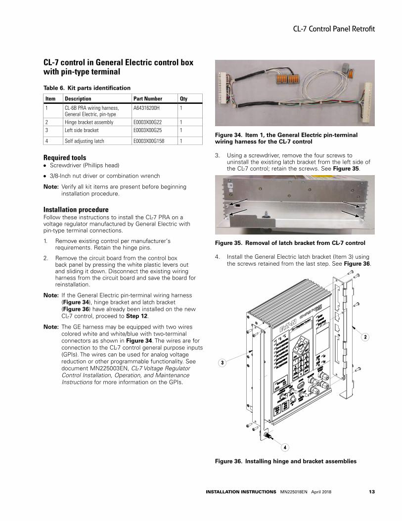
Figure 34 . Item 1, the General Electric pin-terminal wiring harness for the CL-7 control
3. Using a screwdriver, remove the four screws to uninstall the existing latch bracket from the left side of the CL-7 control; retain the screws. See Figure 35.
Figure 35 . Removal of latch bracket from CL-7 control
4. Install the General Electric latch bracket (Item 3) using the screws retained from the last step. See Figure 36.
3
2
4
Figure 36 . Installing hinge and bracket assemblies
13
CL-7 Control Panel Retrofit
InstallatIon InstructIons MN225018EN April 2018
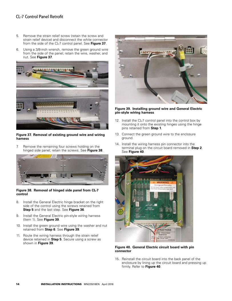
5. Remove the strain relief screw (retain the screw and strain relief device) and disconnect the white connector from the side of the CL-7 control panel. See Figure 37.
6. Using a 3/8-inch wrench, remove the green ground wire from the side of the panel; retain the wire, washer, and nut. See Figure 37.
Figure 37 . Removal of existing ground wire and wiring harness
7. Remove the remaining four screws holding on the hinged side panel; retain the screws. See Figure 38.
Figure 38 . Removal of hinged side panel from CL-7 control
8. Install the General Electric hinge bracket on the right side of the control using the screws retained from Step 5 and the last step. See Figure 36.
9. Install the General Electric pin-style wiring harness (Item 1). See Figure 39.
10. Install the green ground wire using the washer and nut retained from Step 6. See Figure 39.
11. Route the wiring harness through the strain relief device retained in Step 5. Secure using a screw as shown in Figure 39.
Figure 39 . Installing ground wire and General Electric pin-style wiring harness
12. Install the CL-7 control panel into the control box by mounting it onto the existing hinges using the hinge pins retained from Step 1.
13. Connect the green ground wire to the enclosure ground.
14. Install the wiring harness pin connector into the terminal plug on the circuit board removed in Step 2. See Figure 40.
Figure 40 . General Electric circuit board with pin connector
15. Reinstall the circuit board into the back panel of the enclosure by lining up the circuit board and pressing up firmly. Refer to Figure 40.
14
CL-7 Control Panel Retrofit
InstallatIon InstructIons MN225018EN April 2018
16. Close and secure the CL-7 control panel using the self-adjusting latch.
17. Review the General Electric nameplate to determine correct overall Potential Transformer (PT) ratio entered at FC 44 on control.
18. Complete the control programming and testing as required. Refer to document MN225003EN, CL-7 Control Installation, Operation, and Maintenance Instructions for proper control configuration and start up procedures.
IMPORTANTIf the neutral light does not illuminate when the regulator is in neutral, try flipping the neutral light switch to the opposite position. See Figure 14.
15
CL-7 Control Panel Retrofit
InstallatIon InstructIons MN225018EN April 2018

CL-7 control in Howard Industries control box
Table 7 . Kit Parts Identification
Item Description Part Number Qty
1 CL-7 PRA wiring harness, Siemens/Howard control
A64316200F 1
2 Right Faceplate E0003X00G29 13 Latch E0003X00G31 1
4 Shoulder screw 0800071110Z 2
5 SS flat washer, #6 0800019079Z 2
6 Lock Nut, 6-32 hex 0800071115Z 1
7 Left hinge bracket E0003X00G32 1
8 Hinge E0003X00G47 2
9 SS machine screw, 6-32X0.38 0800071090Z 4
10 SS Lock washer, #6 0800070916Z 4
11 Ground lead E0003X00G160 1
12 Adhesive cable-tie anchors 0800069825Z 2
13 Cable tie 0800011079Z 2
Required tools●● Screwdriver (standard)
●● Screwdriver (Phillips head)
●● 3/8-Inch nut driver or combination wrench
●● 5/16-Inch nut driver or combination wrench
otee:N Verify all kit items are present before beginning installation procedure.
Installation procedureFollow these instructions to install the CL-7 PRA on a voltage regulator manufactured by Howard Industries.
1. Remove existing control per manufacturer‘s requirements. Retain the hinge pins and terminal block wing-nuts.
otee:N If the Howard Industries style wiring harness (Figure 41), hinge bracket and latch bracket (Figure 43) have already been installed on the control, proceed to Step 14.
otee:N The Howard Industries harness may be equipped with two wires colored white and white/blue with two-terminal connectors as shown in Figure 41. The wires are for connection to the CL-7 control general purpose inputs (GPIs). The wires can be used for analog voltage reduction or other programmable functionality. See document MN225003EN, CL-7 Voltage Regulator Control Installation, Operation, and Maintenance Instructions for more information on the GPIs.
Figure 41 . Item 1, Howard Industries wiring harness for the CL-7 control
2. Using a screwdriver, remove the four screws to uninstall the existing latch bracket from the left side of the CL-7 control; retain the screws. See Figure 42.
Figure 42 . Removal of latch bracket from CL-7 control
3. Install the left hinge bracket (Item 7) using the screws retained from the last step. See Figure 43.
4. Install the hinges (Item 8) using the provided screws and washers, (Items 9 and 10). See Figure 43.
16
CL-7 Control Panel Retrofit
InstallatIon InstructIons MN225018EN April 2018
2
3
4
5
6
7
8
8
9
10
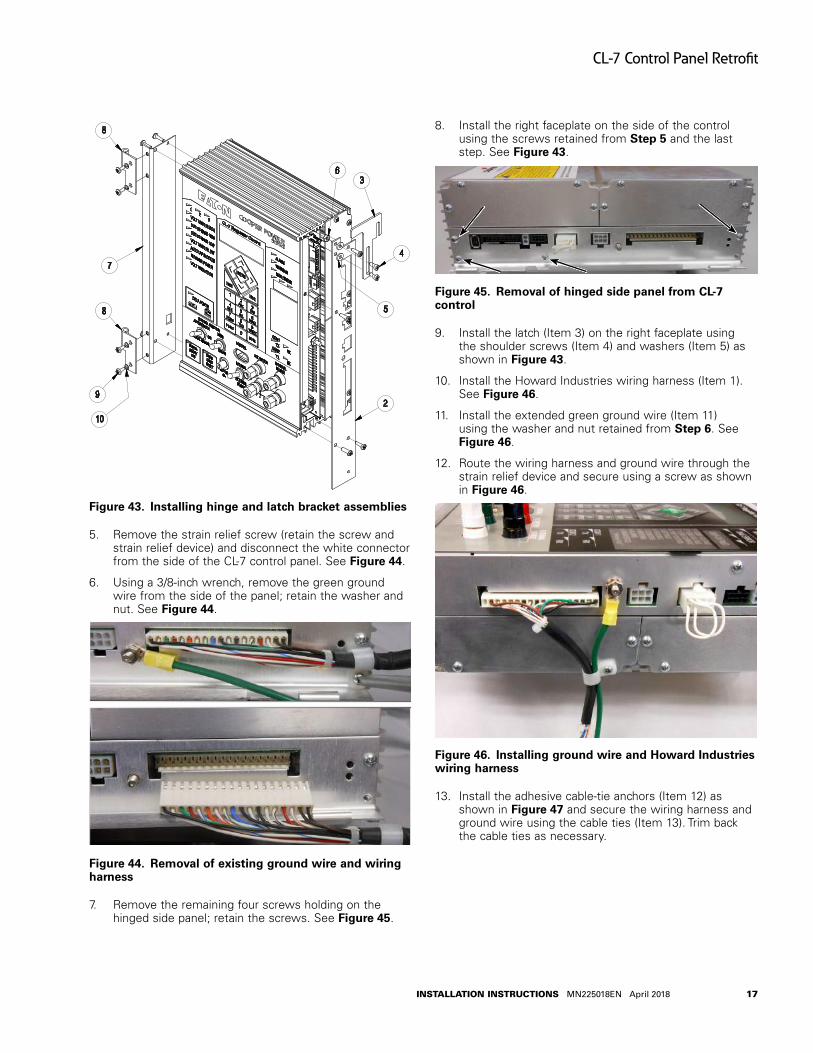
Figure 43 . Installing hinge and latch bracket assemblies
5. Remove the strain relief screw (retain the screw and strain relief device) and disconnect the white connector from the side of the CL-7 control panel. See Figure 44.
6. Using a 3/8-inch wrench, remove the green ground wire from the side of the panel; retain the washer and nut. See Figure 44.
Figure 44 . Removal of existing ground wire and wiring harness
7. Remove the remaining four screws holding on the hinged side panel; retain the screws. See Figure 45.
8. Install the right faceplate on the side of the control using the screws retained from Step 5 and the last step. See Figure 43.
Figure 45 . Removal of hinged side panel from CL-7 control
9. Install the latch (Item 3) on the right faceplate using the shoulder screws (Item 4) and washers (Item 5) as shown in Figure 43.
10. Install the Howard Industries wiring harness (Item 1). See Figure 46.
11. Install the extended green ground wire (Item 11) using the washer and nut retained from Step 6. See Figure 46.
12. Route the wiring harness and ground wire through the strain relief device and secure using a screw as shown in Figure 46.
Figure 46 . Installing ground wire and Howard Industries wiring harness
13. Install the adhesive cable-tie anchors (Item 12) as shown in Figure 47 and secure the wiring harness and ground wire using the cable ties (Item 13). Trim back the cable ties as necessary.
17
CL-7 Control Panel Retrofit
InstallatIon InstructIons MN225018EN April 2018
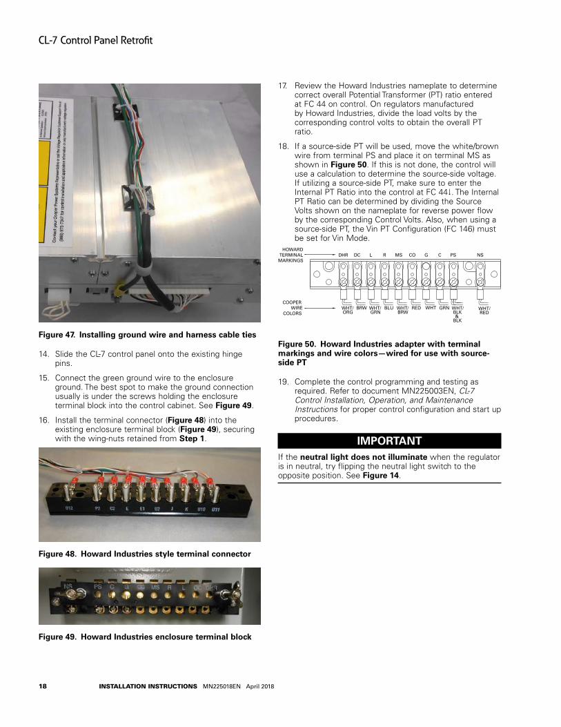
Figure 47 . Installing ground wire and harness cable ties
14. Slide the CL-7 control panel onto the existing hinge pins.
15. Connect the green ground wire to the enclosure ground. The best spot to make the ground connection usually is under the screws holding the enclosure terminal block into the control cabinet. See Figure 49.
16. Install the terminal connector (Figure 48) into the existing enclosure terminal block (Figure 49), securing with the wing-nuts retained from Step 1.
Figure 48 . Howard Industries style terminal connector
Figure 49 . Howard Industries enclosure terminal block
17. Review the Howard Industries nameplate to determine correct overall Potential Transformer (PT) ratio entered at FC 44 on control. On regulators manufactured by Howard Industries, divide the load volts by the corresponding control volts to obtain the overall PT ratio.
18. If a source-side PT will be used, move the white/brown wire from terminal PS and place it on terminal MS as shown in Figure 50. If this is not done, the control will use a calculation to determine the source-side voltage. If utilizing a source-side PT, make sure to enter the Internal PT Ratio into the control at FC 44. The Internal PT Ratio can be determined by dividing the Source Volts shown on the nameplate for reverse power flow by the corresponding Control Volts. Also, when using a source-side PT, the Vin PT Configuration (FC 146) must be set for Vin Mode.
DHR DC L R MS CO G C PS NSHOWARD
TERMINAL MARKINGS
COOPER WIRE
COLORS
WHT/ORG
BRW WHT/GRN
BLU WHT/BRW
RED WHT GRN WHT/BLK&
BLK
WHT/RED
Figure 50 . Howard Industries adapter with terminal markings and wire colors—wired for use with source-side PT
19. Complete the control programming and testing as required. Refer to document MN225003EN, CL-7 Control Installation, Operation, and Maintenance Instructions for proper control configuration and start up procedures.
IMPORTANTIf the neutral light does not illuminate when the regulator is in neutral, try flipping the neutral light switch to the opposite position. See Figure 14.
18
CL-7 Control Panel Retrofit
InstallatIon InstructIons MN225018EN April 2018

his page is intentionally left blank.T
19
CL-7 Control Panel Retrofit
InstallatIon InstructIons MN225018EN April 2018

Eaton1000 Eaton BoulevardCleveland, OH 44122United StatesEaton.com
Eaton’s Power Systems Division2300 Badger DriveWaukesha, WI 53188United StatesEaton.com/cooperpowerseries
© 2018 EatonAll Rights ReservedPrinted in USAPublication No. MN225018ENApril 2018
Eaton is a registered trademark.
All trademarks are property of their respective owners.
For Eaton‘s Cooper Power series product information call 1-877-277-4636 or visit: www.eaton.com/cooperpowerseries.
!SAFETYFOR LIFE