city of tampa · pam iorio, mayor addendum no. 3 date: ... provide standard fence components and...
TRANSCRIPT

CITY OF TAMPA
CONTRACT ADMINISTRATION DEPARTMENT
David L. Vaughn, AIA, Director
306 E. Jackson Street, 4N • Tampa, Florida 33602 • (813) 274-8456 • FAX: (813) 274-8080
Pam Iorio, Mayor
ADDENDUM NO. 3
DATE: August 10, 2009
Contract No. 09-C-00032; Fire Station 22 Improvements Bidders on the above referenced project are hereby notified that the following addendum is made to the Contract Documents. BIDS TO BE SUBMITTED SHALL CONFORM TO THIS NOTICE. Item 1: Replace Sheet P-3 with P-3R Item 2: Utility fee clarification: Water, Sewer, and Building permit fees are being paid for by the City of
Tampa. Temporary and final Teco power connection fees shall be paid for by the Contractor. Item 3: Flagpole Clarification: Design speed for pole is 130 mph. Item 4: Refrigerator quantity clarification: Provide 3
Item 5: Roof felt clarification: Follow specifications 15# requirement. Item 6: Solid surface countertop clarification: countertops shall be part of the toilet compartment provisions of section 10155. Section 10155 header shall be deleted. Item 7: Sheet A-6.2, detail 1 clarification: delete keynote 19 as a requirement. Item 8: Insert into the specifications, after page 09651-7, the attached Section 09680 - Carpet. Item 9: Specification 07211 clarification: delete all references to Seminole Garden Center. Item 10: Sheet C-9 PVC fire main and FHA location clarification: Revise 4” PVC fire main to 6” fire main from right of way to FHA, which should be centered on pond. From FHA to building sprinkler connection provide 4” PVC fire main. Item 11: Sheet P-6.0 clarification: Revise 2 ½” water line into building to 2” to match civil drawings. Item 12: Sheet C-17 fence clarification: Provide 4’ high black vinyl, 9 gage fence running the entire length of the retaining wall plus 12’ on both ends. Provide standard fence components and accessories. Fence posts shall be 6’on center.

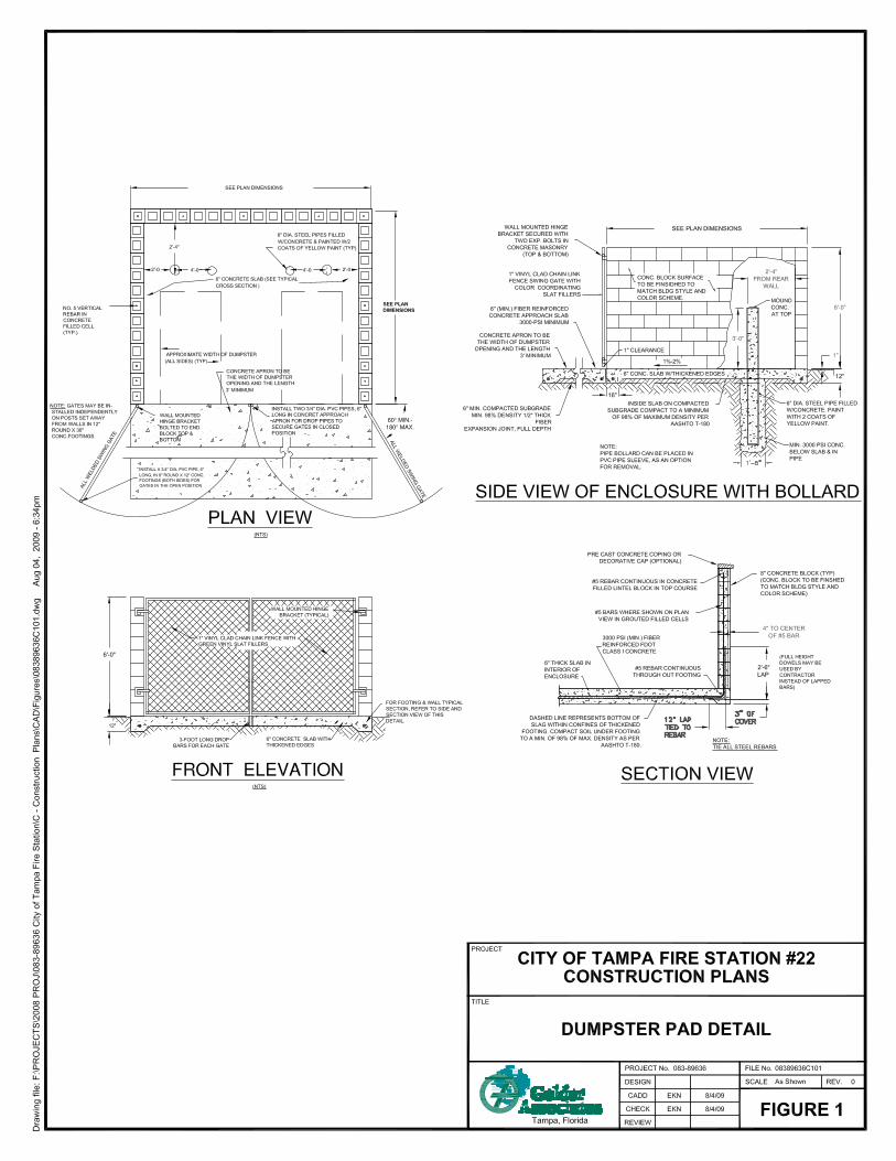
Fire Station 22 Improvements Addendum 3 August 5, 2009 Page 2 Item 13: Add attached Dumpster enclosure detail. Item 14: Section 09255, sand textured finish clarification: provide textured finish as recommended by gypsum board manufacturer i.e. USG or equal. Item 15: Delete Section 23 09 23 from sheet M-7.1, and replace with attached HVAC controls specification. Item 16: Delete Section 23 05 03 Pipes and Tubes for HVAC Piping and Equipment from sheet M-7.0. Follow Section 23 21 13 Hydronic Piping, 2.03 Condensate Drain on Sheet M-7.1. Item 17: For Section 23 05 48 Vibration Controls for HVAC Piping & Equipment on page M-7.0, 3.03 Isolator Schedule, the following items and isolators shall be added.
a. Inline Fans using Spring Hangers. b. Air Handlers using a neoprene pad on a 6” housekeeping pad. c. Chiller on a neoprene pad.
Item 18: Sheet A-8.1 clarification: revise quarry tile size from 8x8 to 6x6.
Item 19: Dishwasher specification clarification: Dishwasher shall be GE PDWT580PSS, or equal.
Item 20: Sheet C-9; manhole clarification: MH-1D12 is existing.
Item 21: Sheet A-7.1 Clarifications: On plan ‘A’ keynote 12 relates to bunker gear count in Bunker room 106; Quarters locker requirements are 3 for each crew quarter room and Chief and Captain rooms; Locker size is revised to 24”Wx18”Dx72”H; Keynote 10 relates to both ice machines as specified; TV’s brackets and units are City-provided, City- installed.
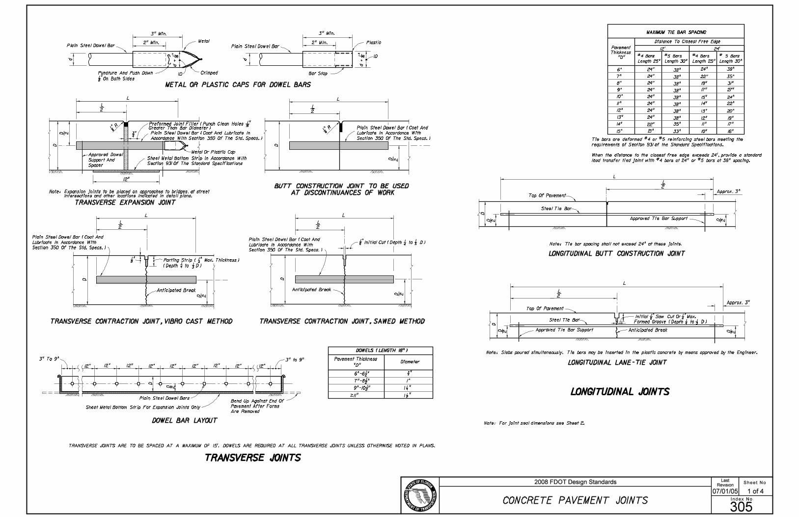
Item 22: Concrete drives clarification is as follows and per attached FDOT Index No. 305: A. 8” Concrete (Class 1 Concrete, 3000 psi) per FDOT Specification Section 347. B. 6” coarse aggregate, or limerock base material, compacted to a density greater than 98
percent of modified Proctor maximum dry density and a minimum Limerock Bearing Ratio (LBR) of 100.
C. 12” subgrade stabilized (Type B Stabilization per FDOT Specification 160) and compacted to a density greater than 98 percent of the modified Proctor maximum dry density and a minimum LBR of 40.
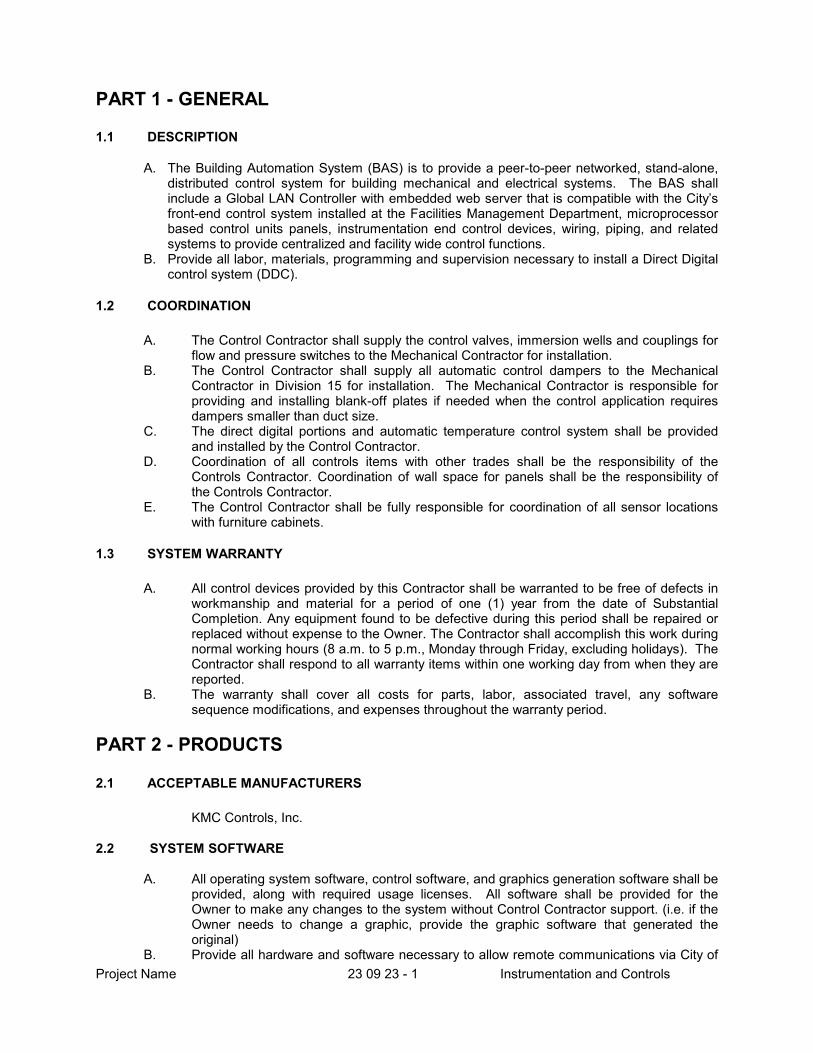
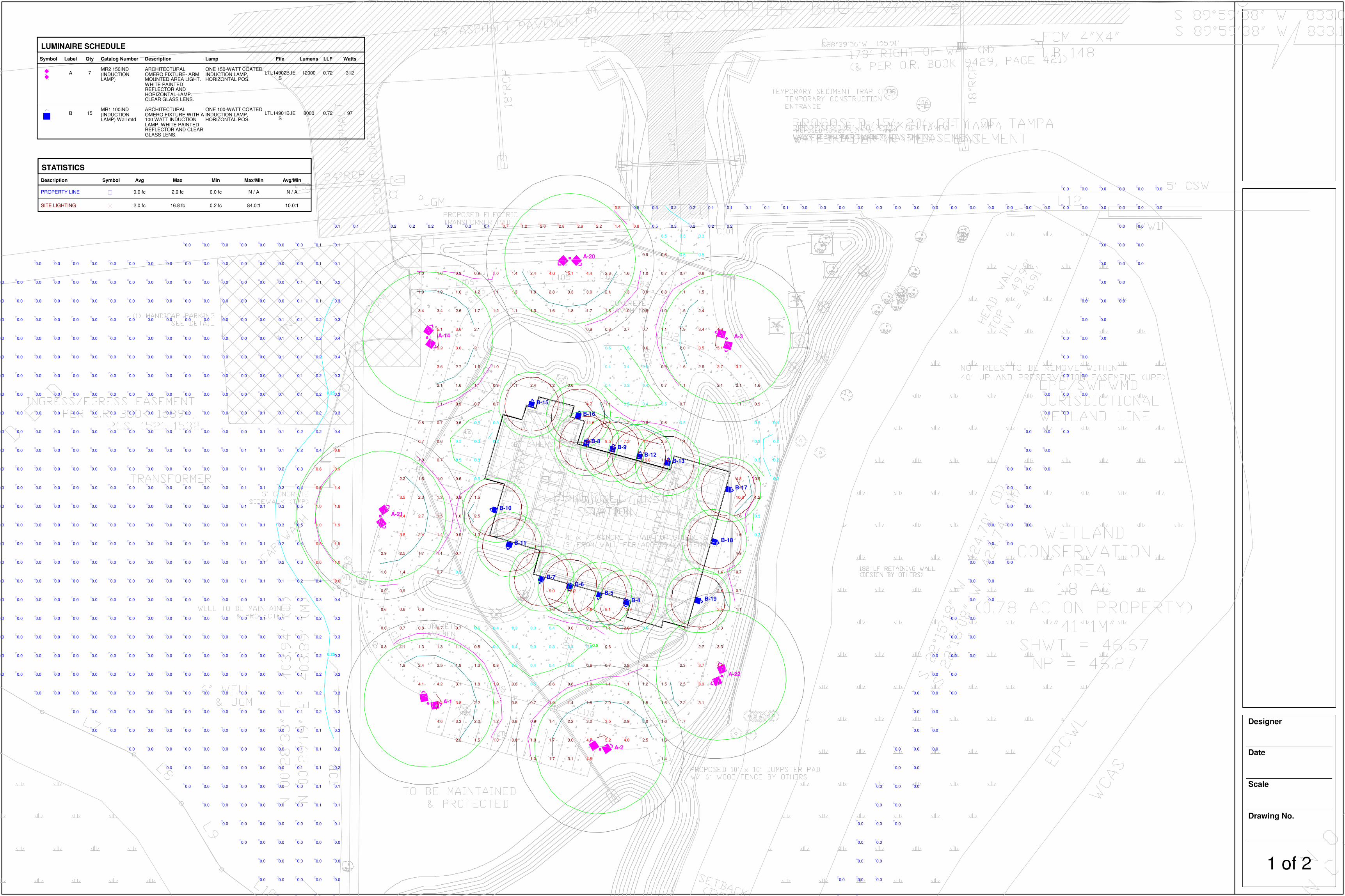
Item 23: Sheet E1.2 Light Pole Clarification: Add one pole 2SB on north end of site between edge of
pavement and pond ‘c’ approximately 45 feet west of the access drive. See attached Luminaire Schedule drawing.

Item 24: Decon room shower clarification: Shower fixture head shall be American Standard
2064.724, or equal.
Fire Station 22 Improvements Addendum 3 August 5, 2009 Page 3
Item 25: Section 11451, page 2: Delete residential appliance section. Appliance schedule is indicated
on pages 3 and 4 of specification.
Item 26: Sheet A-7.1, shelving clarification: shelves in pantry shall be wire type.
Item 27: Roof sheathing clarification: Revise all architectural notes regarding roof sheathing to 5/8” inch plywood sheathing in lieu of 3/4”.
Item 28: Sheet A-6.2, Section 1: Add ½” plywood sheathing on vertical leg of hip jack truss separating building attic from porch attic. Apply 6” foam to surface.
Item 29: Sheet A-3.1, downspout clarification: Provide ten (10) 4” downspouts and concrete splash pads to be field located and coordinated with gutter locations as shown on the documents.
This addendum shall be included in and attached to the inside cover of the Contract Documents by and upon which bids are submitted. All other provisions of the Contract Documents and Specifications not in conflict with this Addendum shall remain in full force and effect. Questions are to be e-mailed to Contract [email protected]. ____________________________________________
Jim Greiner, P.E., Contract Manager Contract Administration Department
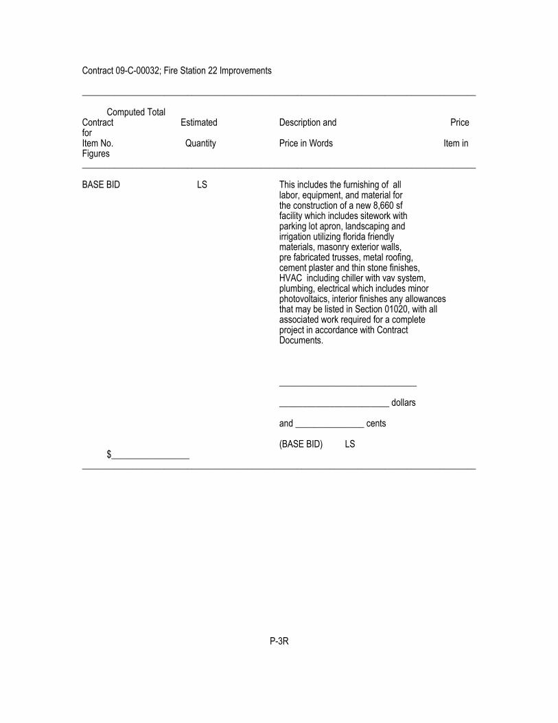
Contract 09-C-00032; Fire Station 22 Improvements ______________________________________________________________________________________ Computed Total Contract Estimated Description and Price for Item No. Quantity Price in Words Item in Figures ______________________________________________________________________________________ BASE BID LS This includes the furnishing of all labor, equipment, and material for the construction of a new 8,660 sf facility which includes sitework with parking lot apron, landscaping and irrigation utilizing florida friendly materials, masonry exterior walls, pre fabricated trusses, metal roofing, cement plaster and thin stone finishes, HVAC including chiller with vav system, plumbing, electrical which includes minor photovoltaics, interior finishes any allowances that may be listed in Section 01020, with all associated work required for a complete project in accordance with Contract Documents. ______________________________ ________________________ dollars and _______________ cents (BASE BID) LS $_________________ ______________________________________________________________________________________
P-3R


Contract 09-C-00032; Fire Station 22 Improvements
CARPET 09680 - 1
SECTION 09680 - CARPET
PART 1 - GENERAL
RELATED DOCUMENTS
Drawings and general provisions of the Contract, including General and Supplementary Conditions and Division 1
Specification Sections, apply to this Section.
SUMMARY
This Section includes carpet, carpet cushion, and installation.
Related Sections: The following Sections contain requirements that relate to this Section:
Division 3 Sections for curing compounds and other concrete treatments compatibility with carpet and carpet
cushion adhesives.
Division 9 Section "Resilient Wall Base and Accessories" for materials and installation.
SUBMITTALS
General: Submit each item in this Article according to the Conditions of the Contract and Division 1 Specification
Sections.
Product Data for each type of carpet material, carpet cushion, and installation accessory specified. Submit
manufacturer's printed data on physical characteristics, durability, fade resistance, and fire-test-response characteristics.
Submit methods of installation for each type of substrate.
Shop Drawings showing columns, doorways, enclosing walls or partitions, built-in cabinets, and locations where cutouts
are required in carpet. Indicate the following:
Carpet type, color, and dye lot.
Locations where dye lot changes occur.
Seam locations, types, and methods.
Type of subfloor.
Type of installation.
Pattern type, repeat size, location, direction, and starting point.
Pile direction.
Type, color, and location of insets and borders.
Type, color, and location of edge, transition, and other accessory strips.
Transition details to other flooring materials.

Contract 09-C-00032; Fire Station 22 Improvements
CARPET 09680 - 2
Samples for initial selection in the form of manufacturer's color charts or Samples of materials showing the full range of
colors, textures, and patterns available for each type of carpet indicated.
Samples for verification of the following products, in manufacturer's standard sizes, showing the full range of color,
texture, and pattern variations expected. Prepare Samples from the same material to be used for the Work. Label each
sample with manufacturer's name, material type, color, pattern, and designation indicated on Drawings and carpet
schedule. Submit the following:
12-inch- (300-mm-) square Samples of each type of carpet material required.
12-inch (300-mm) Samples of each type of exposed edge stripping and accessory item.
Schedule of carpet using same room designations indicated on Drawings.
Maintenance data for carpet and cushion to include in the operation and maintenance manual specified in Division 1.
Include the following:
Methods for maintaining carpet and carpet cushion, including manufacturer's recommended frequency for
maintaining carpet.
Precautions for cleaning materials and methods that could be detrimental to finishes and performance. Include
cleaning and stain-removal products and procedures.
QUALITY ASSURANCE
Installer Qualifications: Engage an experienced Installer who is certified by the Floor Covering Installation Board (FCIB)
or who can demonstrate compliance with FCIB certification program requirements.
Manufacturer Qualifications: Engage a firm whose carpet materials comply with the U.S. Department of Housing and
Urban Development's (HUD) "Use of Materials Bulletin UM-44D" and are currently listed on HUD's "Certified Products
Directory" and so identified by imprint on back of carpet.
Single-Source Responsibility: Obtain each type of carpet from one source and by a single manufacturer.
Carpet Fire-Test-Response Characteristics: Provide carpet with the following fire-test-response characteristics as
determined by testing identical products per test method indicated below by UL or another testing and inspecting
agency acceptable to authorities having jurisdiction. Identify carpet with appropriate markings of applicable testing and
inspecting agency.
Surface Flammability: Passes CPSC 16 CFR, Part 1630.
Flame Spread: 25 or less per ASTM E 84.
Smoke Developed: 450 or less per ASTM E 84.
DELIVERY, STORAGE, AND HANDLING
General: Comply with the Carpet and Rug Institute's CRI 104, Section 5: "Storage and Handling."
Deliver materials to Project site in original factory wrappings and containers, labeled with identification of manufacturer,
brand name, and lot number.

Contract 09-C-00032; Fire Station 22 Improvements
CARPET 09680 - 3
Store materials on-site in original undamaged packages, inside well-ventilated area protected from weather, moisture,
soilage, extreme temperatures, and humidity. Lay flat, with continuous blocking off ground.
PROJECT CONDITIONS
General: Comply with CRI 104, Section 6: "Site Conditions."
Space Enclosure and Environmental Limitations: Do not install carpet until space is enclosed and weatherproof, wet-
work in space is completed and nominally dry, work above ceilings is complete, and ambient temperature and humidity
conditions are and will be continuously maintained at values near those indicated for final occupancy.
Subfloor Moisture Conditions: Moisture emission rate of not more than 3 lb/1000 sq. ft./24 hours (14.6 kg/1000 sq. m/24
hours) when tested by calcium chloride moisture test in compliance with CRI 104, 6.2.1, with subfloor temperatures not
less than 55 deg F (12.7 deg C).
Subfloor Alkalinity Conditions: A pH range of 5 to 9 when subfloor is wetted with potable water and pHydrion paper is
applied.
WARRANTY
General Warranty: The special warranty specified in this Article shall not deprive the Owner of other rights the Owner
may have under other provisions of the Contract Documents and shall be in addition to, and run concurrent with, other
warranties made by the Contractor under requirements of the Contract Documents.
Special Carpet Warranty: Submit a written warranty executed by carpet manufacturer and Installer agreeing to repair or
replace carpet that does not meet requirements or that fails in materials or workmanship within the specified warranty
period. Failures include, but are not limited to, more than 10 percent loss of face fiber, edge raveling, snags, runs, and
delamination.
Warranty Period: 5 years from date of Substantial Completion.
Special Carpet Cushion Warranty: Submit a written warranty executed by carpet cushion manufacturer and Installer
agreeing to repair or replace carpet cushion that does not meet requirements or that fails in materials or workmanship
within the specified warranty period. Failures include, but are not limited to, permanent indentation or compression.
Warranty Period: 5 years from date of Substantial Completion.
EXTRA MATERIALS
Furnish extra materials described below that match products installed, are packaged with protective covering for
storage, and are identified with labels clearly describing contents.
Carpet: Before installation begins, furnish quantity of full-width units equal to 5 percent of amount installed.
PART 2 - PRODUCTS
CARPET
Available Products: Subject to compliance with requirements, products that may be incorporated in the Work include,
but are not limited to, the products specified in each carpet Product Data sheet at end of this Section.

Contract 09-C-00032; Fire Station 22 Improvements
CARPET 09680 - 4
Products: Subject to compliance with requirements, provide one of the products specified in each carpet Product Data
sheet at end of this Section.
INSTALLATION ACCESSORIES
Concrete-Slab Primer: Nonstaining type as recommended by the following:
Trowelable Underlayments and Patching Compounds: As recommended by the following:
Carpet manufacturer.
Adhesives: Water-resistant, mildew-resistant, nonstaining type to suit products and subfloor conditions indicated and to
comply with flammability requirements for installed carpet as recommended by the following:
Carpet manufacturer.
Tackless Carpet Stripping: Water-resistant plywood in strips as required to match cushion thickness and in compliance
with CRI 104, 11.3.
Seaming Cement: Hot-melt adhesive tape or similar product recommended by carpet manufacturer for taping seams
and butting cut edges at backing to form secure seams and to prevent pile loss at seams.
PART 3 - EXECUTION
EXAMINATION
Examine subfloors and conditions, with Installer present, for compliance with requirements for maximum moisture
content, alkalinity range, installation tolerances, and other conditions affecting performance of carpet. Do not proceed
with installation until unsatisfactory conditions have been corrected.
Verify that subfloors and conditions are satisfactory for carpet installation and comply with requirements specified in this
Section and those of the following:
Carpet manufacturer.
Carpet cushion manufacturer.
PREPARATION
General: Comply with carpet manufacturer's installation recommendations to prepare substrates indicated to receive
carpet installation.
Level subfloor within 1/4 inch in 10 feet (6 mm in 3 m), noncumulative, in all directions. Sand or grind protrusions,
bumps, and ridges. Patch and repair cracks and rough areas. Fill depressions.
Use leveling and patching compounds to fill cracks, holes, and depressions in subfloor as recommended by the
following:
Carpet manufacturer.
Broom or vacuum clean subfloors to be covered with carpet. Following cleaning, examine subfloors for moisture,
alkaline salts, carbonation, or dust.

Contract 09-C-00032; Fire Station 22 Improvements
CARPET 09680 - 5
Concrete-Subfloor Preparation: Apply concrete-slab primer, according to manufacturer's directions, where
recommended by the following:
Carpet manufacturer.
INSTALLATION
Direct Glue-Down Installation: Comply with CRI 104, Section 8: "Direct Glue-Down."
Comply with carpet manufacturer's recommendations for seam locations and direction of carpet; maintain uniformity of
carpet direction and lay of pile. At doorways, center seams under door in closed position. Do not bridge building
expansion joints with continuous carpet.
Where demountable partitions or other items are indicated for installation on top of finished carpet floor, install carpet
before installation of these items.
Cut and fit carpet to butt tightly to vertical surfaces, permanent fixtures, and built-in furniture including cabinets, pipes,
outlets, edgings, thresholds, and nosings. Bind or seal cut edges as recommended by carpet manufacturer.
Extend carpet into toe spaces, door reveals, closets, open-bottomed obstructions, removable flanges, alcoves, and
similar openings.
Install pattern parallel to walls and borders.
Install carpet cushion seams at 90-degree angle with carpet seams.
CLEANING
Perform the following operations immediately after completing installation.
Remove visible adhesive, seam sealer, and other surface blemishes using cleaner recommended by carpet
manufacturer.
Remove protruding yarns from carpet surface.
Vacuum carpet using commercial machine with face-beater element.
PROTECTION
General: Comply with CRI 104, Section 15: "Protection of Indoor Installation."
Provide final protection and maintain conditions, in a manner acceptable to manufacturer and Installer, that ensure
carpet is without damage or deterioration at the time of Substantial Completion.
PRODUCT DATA SHEET 1 - CARPET
Carpet Designation: MOHAWK SUPERTRON SD-49445
Construction Woven Interlock
Pitch 165.P.O.B.
Pile Height as Woven .200 in. (.169 in. Finished)
Pile Thickness .113 in.
Contract 09-C-00032; Fire Station 22 Improvements
CARPET 09680 - 6
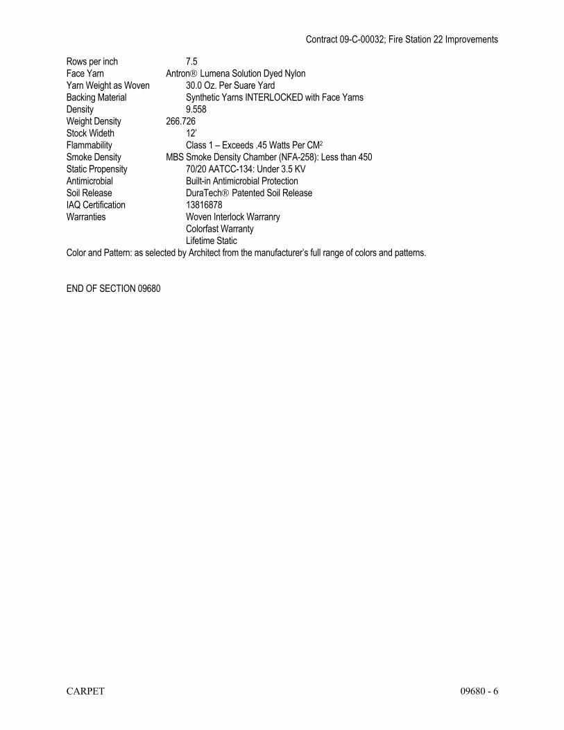
Rows per inch 7.5
Face Yarn Antron Lumena Solution Dyed Nylon
Yarn Weight as Woven 30.0 Oz. Per Suare Yard
Backing Material Synthetic Yarns INTERLOCKED with Face Yarns
Density 9.558
Weight Density 266.726
Stock Wideth 12’
Flammability Class 1 – Exceeds .45 Watts Per CM2
Smoke Density MBS Smoke Density Chamber (NFA-258): Less than 450
Static Propensity 70/20 AATCC-134: Under 3.5 KV
Antimicrobial Built-in Antimicrobial Protection
Soil Release DuraTech Patented Soil Release
IAQ Certification 13816878
Warranties Woven Interlock Warranry
Colorfast Warranty
Lifetime Static
Color and Pattern: as selected by Architect from the manufacturer’s full range of colors and patterns.
END OF SECTION 09680
Project Name 23 09 23 - 1 Instrumentation and Controls
PART 1 - GENERAL
1.1 DESCRIPTION
A. The Building Automation System (BAS) is to provide a peer-to-peer networked, stand-alone,
distributed control system for building mechanical and electrical systems. The BAS shall include a Global LAN Controller with embedded web server that is compatible with the City’s front-end control system installed at the Facilities Management Department, microprocessor based control units panels, instrumentation end control devices, wiring, piping, and related systems to provide centralized and facility wide control functions.
B. Provide all labor, materials, programming and supervision necessary to install a Direct Digital control system (DDC).
1.2 COORDINATION
A. The Control Contractor shall supply the control valves, immersion wells and couplings for
flow and pressure switches to the Mechanical Contractor for installation. B. The Control Contractor shall supply all automatic control dampers to the Mechanical
Contractor in Division 15 for installation. The Mechanical Contractor is responsible for providing and installing blank-off plates if needed when the control application requires dampers smaller than duct size.
C. The direct digital portions and automatic temperature control system shall be provided and installed by the Control Contractor.
D. Coordination of all controls items with other trades shall be the responsibility of the Controls Contractor. Coordination of wall space for panels shall be the responsibility of the Controls Contractor.
E. The Control Contractor shall be fully responsible for coordination of all sensor locations with furniture cabinets.
1.3 SYSTEM WARRANTY
A. All control devices provided by this Contractor shall be warranted to be free of defects in
workmanship and material for a period of one (1) year from the date of Substantial Completion. Any equipment found to be defective during this period shall be repaired or replaced without expense to the Owner. The Contractor shall accomplish this work during normal working hours (8 a.m. to 5 p.m., Monday through Friday, excluding holidays). The Contractor shall respond to all warranty items within one working day from when they are reported.
B. The warranty shall cover all costs for parts, labor, associated travel, any software sequence modifications, and expenses throughout the warranty period.
PART 2 - PRODUCTS
2.1 ACCEPTABLE MANUFACTURERS
KMC Controls, Inc.
2.2 SYSTEM SOFTWARE A. All operating system software, control software, and graphics generation software shall be
provided, along with required usage licenses. All software shall be provided for the Owner to make any changes to the system without Control Contractor support. (i.e. if the Owner needs to change a graphic, provide the graphic software that generated the original)
B. Provide all hardware and software necessary to allow remote communications via City of

Project Name 23 09 23 - 2 Instrumentation and Controls
Tampa Intranet from the existing KMC Controls front-end computer located in the Facilities Department to the off-site location.
2.3 System Controllers, Field Panels, Local Controllers, Global Controllers, Etc.
A. Global LAN Controller Panel (GC/LAN)
Note: The basis of design is a system that does not require a Global Controller/LAN Controller unless more than a single sub LAN is required. All Field Panels, Local Controllers or other addressable devices communicating on a sub LAN must utilize Peer-to-Peer communications and not require a GC/LAN device to pass information between the devices on the LAN. Systems that do not meet this requirement are not allowed.
The GC/LAN shall be capable of operating in a stand alone or in a Peer-to-Peer network environment. Like the Field Panels, the GC/LAN shall have on-board I/O points directly controlled by the GC/LAN programming. Other on board features shall include: A. Stand-alone or network peer-to-peer capability B. Universal inputs-software selectable as analog or digital with standard and custom
ranges. C. Variable points, software selectable as analog or digital with standard and custom
ranges; may have manually set or program driven values. D. Alarm buffering up to 256 alarms, 50 alarm messages for distribution E. P, PI, or PID controllers F. User definable control basic programs G. Trend Logs H. Runtime logs I. System control groups for organizing controller selected points or elements into a real
time display or color graphic. J. Weekly time schedules with overrides K. Annual routines for holiday schedules L. 6 Access levels with 256 individual user passwords M. Power-fail with auto restart capabilities N. Programs and program parameters are stored in non-volatile flash memory O. Embedded Web Server to serve customized web pages containing any desired I/O
values from the entire BAS
B. VAV-TERMINAL UNIT CONTROLLER (VAV-TUC)
The VAV-TUC is a fully programmable direct digital controller, integrated into an actuator, for VAV terminal units. This controller will operate independently in a standalone mode or jointly in a peer-to-peer network sharing system data and/or programs. Standard VAV control sequences are incorporated to provide pressure independent control of a single duct VAV unit. Programmable control basic allows customizing of the standard sequences for temperature setback, overrides, proportional wet reheat, dual duct and other user defined sequences. Each controller has an onboard flow-thru sensor for use with a single or multi-point differential pressure measuring station or Pitot tube. Features shall include:
a. 4 Inputs, software selected for analog or digital with one dedicated to the flow sensor.
b. 4 Outputs, software selected for analog or digital with one dedicated to the actuator.
c. 32 Variables, software selected for analog or digital. d. 4 P, PI, and/or PID controllers e. 5 user defined control basic programming areas. f. 2 Trend Logs, each log storing up to 4 selected elements at user defined
intervals.

Project Name 23 09 23 - 3 Instrumentation and Controls
g. 2 Run-Time totalizers and event logs. h. 2 Control groups for organizing selected elements in real-time display. i. 3 Custom defined lookup tables. j. Weekly schedule w/Holiday/Special event overrides. k. Password and security level protection.
C. TERMINAL UNIT CONTROLLERS (TUC)
Terminal Unit Controllers shall utilize a high speed RISC processor that will read all inputs, execute all programs and write to all its outputs at least ten (10) times per second. The inputs and the outputs shall be defined in software as an analog input, digital input, analog output, or digital output. The controller shall be able to survive the application of 240 VAC to any input channel and/or the RS-485 communications trunk. The enclosure shall have a UL 94 5V rating or equivalent.
Terminal Unit controllers shall communicate on a full peer-to-peer basis with up to 123 other local controllers and/or terminal unit controllers on the Terminal Unit Controller LAN without the aid of a higher level communications processor. Each of these 124 units shall be able to pass a minimum of thirty-two (32) pieces of data up to the Local Controller LAN and accept a minimum of thirty-two (32) pieces of data from the LAN. The Terminal Unit Controller LAN shall be capable of communicating with remote PC’s, printers, or pagers.
D. PACKAGING AND ENVIRONMENT
Distributed unitary controller enclosures shall be locking type, metal cabinet, with common keying. Indoor panels shall be NEMA 1 enclosures with gaskets. The panel, when required, must functionally operate over a temperature range of 32 degrees F to 120 degrees F, and a humidity range of 0 - 95% non-condensing. DDC panels shall come with a minimum of six pre-existing available knockouts for ease of wiring during installation. The electrical requirements shall be identified and coordinated by the Controls Contractor. Any 110 VAC requirements are to be coordinated with Division 16 Contractor. The division 16 Contractor shall provide 110 VAC power circuits to each panel. 110 VAC power should not be installed in the same panel as 24 VAC. However, if 110 VAC power must be installed in the same panel with 24 VAC power due to design and/or system constraints, the 110 VAC side of the panel shall be physically isolated from the 24VAC side and clearly labeled. Use panduits in each control panel to conceal all wiring. Fuse all transformers.
2.4 MICROPROCESSOR BASED SPACE SENSOR
A. A microprocessor based space sensor residing on a RS-485 network shall provide the
following functions:
1. Space temperature measurement and indication 2. Outside air temperature indication 3. Space temperature setpoint adjustment 4. View the value of any input or output in the system 5. Change the value of any input, output or software point in the system 6. The above functions shall be field programmable if desired
All Terminal unit controllers shall be capable of interface to this microprocessor based room sensor. In addition to the space temperature input, a Digital Input shall also be available at the sensor in addition to all other inputs at the associated controller.

Project Name 23 09 23 - 4 Instrumentation and Controls
The microprocessor based room sensor shall include an RJ11 jack for connection of a PC to the entire LAN network. Microprocessor based sensors whose RJ11 jack only allows communication with the controller to which it is connected shall not be acceptable.
2.5 AUXLLIARY CONTROL DEVICES
A. AUTOMATIC CONTROL DAMPERS AND OPERATORS
1. Automatic control dampers shall have interlocking blades and frames. Dampers shall be designed and constructed so that the blades, frames and linkage mechanism shall present a rigid assembly with free and easy action. Dampers shall be of galvanized steel blades and welded steel frame. The damper bearings shall be brass or oil impregnated nylon with brass bearing shafts. Where the damper blades are installed in a vertical position, a thrust type ball bearing shall be provided for the lower bearing. All bearings in ducts or casings to the outside shall have the top and bottom edges on both ends trimmed with replaceable neoprene seal fastened in an approved manner, so as to be practically air tight when closed. Closed dampers shall have leakage of not more than one-half percent at 4" of water column (10.2 cm) static pressure and 2,000 feet per minute velocity.
2. Approved damper manufacturers are: Metalaire, Ruskin, and Vent products. 3. All modulating dampers shall be sized for an effective linear airflow control
characteristic within the angle of rotation and maximum pressure drop specified. Information shall be provided to the Sheet metal subcontractor for determining the proper duct reductions or baffles used.
4. Damper frames shall not be less than 13 gauge-galvanized steel, formed for extra strength, with mounting holes for enclosed duct mounting.
5. All damper blades shall be of not less than 16 gauge-galvanized steel formed for strength and high velocity performance. Blades on all dampers must not be over 8" in width. Blades shall be secured to 1/2" diameter zinc plated axles by zinc plated bolts and nuts. Blade side edges shall be sealed off against spring stainless steel seals. Teflon coated thrust bearings shall be provided at each end of every blade to minimize torque requirements and insure smooth operation. All blade linkage hardware shall be constructed of corrosion resistant, zinc plated steel and brass.
6. Dampers shall be of the parallel blade design for two- position service and opposed blade design for modulating service.
7. Approved damper operator manufacturers are: � KMC Controls
8. The required number of modulating motors shall operate each automatic damper or section of damper if too large for one motor. The motors shall be of the proper size required to operate the damper with uniform and gradual movement and shall return the damper to the same position for a given signal during an opening or closing movement of the damper. Damper operators shall be of the proportional type capable of accepting 0-10 volts or 4-20 ma control signal and 2-10 VDC feedback signal. The type of operator input signal will be a function of the DDC control panel output.
B. AUTOMATIC CONTROL VALVES AND OPERATORS
1. The Control Contractor shall furnish all the control valves of the type indicated on the drawings for installation by the Mechanical Contractor.
2. All modulating straight-through water valves shall be provided with equal percentage contoured throttling plugs. All modulating three-way mixing valves shall be provided with linear V-port plugs such that the total flow through the valve shall remain constant regardless of the valve's position. All diverting valves shall

Project Name 23 09 23 - 5 Instrumentation and Controls
have two V-port plugs. 3. Valves 2" and smaller shall have brass or bronze bodies with screwed ends.
Valves 2-1/2" and larger shall have iron bodies brass or bronze trimming with flanged ends. Valves shall be factory rated to withstand the pressures encountered. Valves shall have stainless steel stems and spring loaded Teflon packing.
4. Air handling unit water valves shall be sized for a pressure drop equal to the coil they serve but not to exceed 5 psi. Valves shall have replaceable seats and discs. Provide pressure drop at half flow with submittals.
5. All automatic control valves shall be fully modulating type unless specified otherwise by the project engineer.
6. All control valves shall be designed to fail as follows: a. Cooling - Fail fully closed to coil. b. Heating - Fail fully open to coil.
7. Each valve operator shall be 4-20mA type, with manual position override and feedback.
8. Ball control valves are acceptable. 9. Valves actuators shall be mounted vertical only. 10. Approved valve and valve actuator manufacturers are:
� KMC Controls
C. ELECTRONIC TEMPERATURE SENSORS
1. Temperature sensors shall be thermistors or 100 Ohm platinum RTD. Sensors shall be calibrated to less than or equal to a 1/4 degree F resolution for the specific application. All sensors to be field verified as correct.
2. Provide twisted pair lead wires and shield for input circuit or as otherwise required by the manufacturer.
3. Use insertion elements in ducts not affected by temperature stratification or smaller than one square meter. Use averaging elements where larger or prone to stratification. Sensor length 2.5 m or 5 m as required.
4. Insertion elements for liquids shall be brass separable sockets (thermowells) with
minimum insertion length of 2-1/2 inches (60 mm). 5. Provide outside air sensors with watertight inlet fittings, shielded from direct rays
of the sun. Mount in permanent shade away from building heat radiation or fan exhaust preferably on the North side of the facility.
6. Wall mounted sensor shall be mounted at 5'-6" above finished floor in an area which free air current is not constricted or blocked, final location shall be approved by the Owner and Engineer prior to installation.
D. OUTSIDE AIR MONITOR AND CONTROL
1. Each VAV air-handling unit shall have an airflow control station capable of performing constant volume control of outside air without loss of dehumidification at part load. The intent is for the controls to be an integral part of the Building Management and Automatic Temperature Control System.
2. Each airflow monitor and control station shall be complete with velocity pressure transmitter and air volume flow rate control. The differential pressure transducer shall be capable of transmitting a linear 4 to 20 ma output signal proportional to the differential (velocity) pressure input signals.
3. Units to comply with minimum manufacturers up and downstream configuration to be coordinated with Division 15 Contractor.
E. AIRFLOW MEASURING STATIONS (DUCT AIRFLOW MEASURING DEVICE):

Project Name 23 09 23 - 6 Instrumentation and Controls
1. Airflow measuring stations shall be fabricated of heavy galvanized steel welded casing with 90° connecting flanges in a configuration and size equal to that of the duct it is mounted into. Each station shall be complete with an air directionalizer and parallel cell profile suppresser across the entering air stream and mechanically fastened to the casing, equal-area and equal-weighted averaging total pressure sensors and manifold, bullet-nose shaped static pressure sensors with averaging manifold, internal piping, and external pressure transmitter ports. An identification label shall be placed on each unit casing listing model number, size, area, and specified airflow capacity.
2. The maximum allowable pressure loss through the unit shall not exceed 0.1"w.g. Each unit shall be capable of measuring the airflow rate within an accuracy of 2% as determined by U.S. GSA. Certification tests shall contain a minimum of one total pressure sensor per thirty-six square inches of unit measuring area.
3. Stations shall be installed in strict accordance with the manufacturer's published requirements. Final location shall be coordinated with the mechanical or the sheet metal subcontractor. These stations serve as the primary signals for the airflow control systems, therefore it shall be the responsibility of the Contractor to verify location and installation to assure that accurate primary signals are obtained.
4. The units shall have a self-generated sound rating of less than NC40, and the sound level within the duct shall not be amplified nor shall additional sound be generated.
5. Airflow measuring stations shall be Model FAN-E as manufactured by Air Monitor Corporation.
6. The project test & balance contractor shall test each air monitor. Tests shall be conducted at full and part load fan capacity.
Q. CONTROL WIRING
1. All conductors shall be of stranded copper wire. 2. All PVC/EMT/rigid steel conduit and outlet boxes shall conform to the
requirements specified under Division 16, Electrical. 3. All cable runs exposed in return air plenums shall be smoke rated for the
application and secured to the building structure. Do not run wire in drywall without conduit.
4. All wiring cables shall have 600-volt insulation. 5. Cables shall be properly identified/tagged with matching wire markers on both
ends as to the control point. 6. All cables from ceilings to wall temperature sensors shall be installed in conduit
(EMT). EMT Conduit fittings shall be steel compression type. Set Screw fittings are not acceptable.
7. Non-conduit wires (exposed wires above ceiling) will be decided by the detail spec (project scope).
8. All communication wire between buildings shall be fiber optic cable, and shall be installed in the proper raceways as defined by division 16.
3.1 INSTALLATI0N
A. Install control systems and materials in accordance with manufacturer’s instructions, industry
standards, rough-in drawings, and detail drawings. Install electrical components complying with the requirements of Division-16. Mount all control panels at convenient locations and heights.
B. The control equipment and wiring shall be installed in a neat and workmanlike manner by the trained mechanics.
C. Identify each item, mounted on the face of a control panel, with an engraved nameplate (1/4” high engraved letters minimum). Identify each item of control equipment (except room sensors and thermostats), with stamped tape, firmly attached to equipment (1/4” high letters

Project Name 23 09 23 - 7 Instrumentation and Controls
minimum). D. Thermostats or sensors mounted on outside walls shall be mounted on 1” minimum
thickness, rigid fiberglass insulating base (or equal). E. All thermostat bulbs in water lines shall be installed inseparable wells, packed with heat
conductive compound. F. All controllers, relays, transducers, etc., required for stand-alone control shall be housed in
NEMA and UL listed enclosures with a lockable door. The type of NEMA enclosure shall be based upon environmental requirements outlined in the specifications or on the drawings for this project.
G. Provide on interior walls to sense average room temperature conditions. Avoid locations, which may be covered by office furniture. Room temperature sensors should not be mounted on exterior walls when other locations are available. Room thermostats and room sensors shall be mounted approximately 60” above the floor unless ADA codes apply. Devices shall be set level and shall align with adjacent switches, thermostats, etc. for neat appearance.
H. Dampers and valves shall be installed in accordance with manufacturers written instructions, rough-in drawings, and detail drawings.
I. Install control valves in vertical position whenever possible, and in no case shall control valves be installed below a horizontal position.
K. Install control panels in an approved location, convenient for adjustment and service. L. The SI Contractor shall enter all computer programs and data files into the related computers
including all control programs, initial approved parameters and settings, and English descriptors.
M. The SI Contractor shall maintain diskette copies of all data file and application software for reload use in the event of a system crash or memory failure. One copy shall be delivered to the owner during training session, and one copy shall be archived in the SI Contractor’s local software vault.
N. Number-code all conductors for future identification and service of control system. O. DDC components that are to be factory mounted shall be provided by the SI Contractor and
shipped to the equipment manufacturer for installation. Coordination of the factory installation shall be the responsibility of the SI Contractor. Proper operation of factory installed components shall be the responsibility of the SI Contractor.
P. Coordinate with other trades to interface installation of control equipment work with other work.
3.2 ELECTICAL WIRING A. All wiring and conduit shall be run parallel to or at right angles to the building structure, and
shall be concealed in all finished spaces. Wiring may be run exposed in mechanical rooms or areas where other piping or ductwork is exposed.
B. All electrical work performed in the installation of the BAS described in this specification shall be per the National Electrical Code (NEC) and per applicable state and local codes. Circuits operating at 100 volts or less shall be defined as low voltage and shall be run in rigid or flexible conduit, metallic tubing, metal raceways or wire trays, armored cable, or multi-conductor cable. Use multi-conductor cable for concealed accessible locations only where conductors are concealed in return air plenums, cable rated for use in return air plenums shall be used.
C. Raceways installed underground shall be rigid steel, heavy wall, galvanized, threaded conduit. Rigid steel raceways shall be of mild steel piping “electro-galvanized” or “hot-dipped” galvanized inside and outside including threads, couplings, elbows and nipples. Electrical metallic tubing with steel compression type couplings and connectors may be used except underground or where exposed to moisture or outside conditions.
D. All wire conductors shall be copper insulated for 600 volts. All conductors subject to normal ambient temperatures, except for low voltage conductors, shall be type THHN or THWN. Other conductors requiring heat resistant insulation because of condition or location shall be in accordance with the National Electric Code and local requirements.
E. Provide twisted shielded cable for low voltage signal circuits installed in concealed, accessible locations. Cable shall be listed by Underwriter’s Laboratories for its use and conductors shall be minimum 18 gauge, with continuous shielding. All cables installed in air plenums shall be

Project Name 23 09 23 - 8 Instrumentation and Controls
specifically listed for plenum use. F. Class II wiring for the BAS may be run without conduit provided the conductor insulation or
jacket is designed for that purpose, and provided it is protected from physical damage. All control wiring in mechanical spaces must be in metallic conduit. Power line carrier devices may not be used.
G. All system components and sensors must be hard-wired. Minimum size conduit shall be ½”. All cable shall be bundled and neatly strapped to roof joists. Laying wire on top of ceiling shall NOT be allowed.
H. Where wiring in exposed, occupied spaces cannot be concealed, wire mold shall be used. I. Conduits shall not be run concealed under pipe insulation, duct insulation or inside of ducts. J. Bundle and harness multi-conductor instrument cable in place of single cables where several
cables follow a common path. K. Fasten flexible conductors, bridging cabinets and doors, along hinge side; protect against
abrasion. Tie and support conductors. L. Number-code or color-code conductors for future identification and service of control system,
except local individual room control cables.
3.3 TRAINING
A. Training sessions shall be provided for Owner’s personnel by the SI Contractor’s factory
trained control engineers and technicians. B. The SI Contractor shall conduct two 8-hour training courses for designated Owner’s personnel
in maintenance and operation of control system. 1. One class shall be given upon system acceptance and one class approximately 6 months
into warranty. C. Course shall include instruction on specific systems and instructions for operating installed
system to include as a minimum: 1. HVAC system overview. 2. Operation of control system. 3. Function of each component. 4. System operating procedures. 5. Programming procedures. 6. Maintenance procedures. 7. Selection of all displays and reports. 8. Password assignment and modification. 9. Modifications to graphics. 10. Walk-through or the job to locate control components. 11. Operation of portable operations terminal. 12. Explanation of adjustment, calibration and replacement procedures.
Approx. 3"Top Of Pavement
Steel Tie Bar
Approved Tie Bar Support
L
2
D 2D 2
D
L
"D"
Pavement
Thickness
24"
22"
Note: For joint seal dimensions see Sheet 2.
Distance To Closest Free Edge
12’ 24’
MAXIMUM TIE BAR SPACING
6"
7"
8"
9"
10"
11"
12"
13"
14"
15" 21"
38"
35"
33"
24"
22"
19"
17"
15"
14"
13"
12"
11"
10"
38"
35"
31"
27"
24"
22"
19"
17"
16"
20"
LONGITUDINAL BUTT CONSTRUCTION JOINT
D
L
D
L
Plain Steel Dowel Bars
Sheet Metal Bottom Strip For Expansion Joints Only
3" To 9"
D
D 2
D
L
Anticipated BreakAnticipated Break
DOWEL BAR LAYOUT
BUTT CONSTRUCTION JOINT TO BE USED
AT DISCONTINUANCES OF WORK
TRANSVERSE CONTRACTION JOINT, SAWED METHOD
L
2
D 2D 2
L
2
L
2
D 2
3" to 9"
1
4
LONGITUDINAL LANE-TIE JOINT
Initial Cut (Depth to D)
(Depth to D)
1
81
4Parting Strip ( Max. Thickness)
TRANSVERSE CONTRACTION JOINT, VIBRO CAST METHOD
1
8
1
41
3
1
4
1
3
D
L
12"
TRANSVERSE EXPANSION JOINT
L
2
D 2
Preformed Joint Filler (Punch Clean Holes Greater Than Bar Diameter)
16
1
3
4
Metal Or Plastic Cap
3" Min.
2" Min.
3" Min.
2" Min.Plain Steel Dowel Bar Plain Steel Dowel Bar
Puncture And Push Down
On Both Sides
Crimped1
8
Bar Stop
d +
161
dd
Metal Plastic
d +
161
ID
ID
METAL OR PLASTIC CAPS FOR DOWEL BARS
18
R
11"
1"
41
1 "
43
21
1 "
Pavement Thickness
"D"Diameter
"
DOWELS (LENGTH 18")
12" 12" 12" 12" 12" 12" 12" 12" 12"
D
L
TRANSVERSE JOINTS
Steel Tie Bar
Approved Tie Bar Support Anticipated Break
Approx. 3"
Top Of Pavement
D 2D 2
L
2
4 1
3 1
Initial Saw Cut Or Max.
Formed Groove (Depth to D)
1
8
Note: Slabs poured simultaneously. Tie bars may be inserted in the plastic concrete by means approved by the Engineer.
18
R
TRANSVERSE JOINTS ARE TO BE SPACED AT A MAXIMUM OF 15’. DOWELS ARE REQUIRED AT ALL TRANSVERSE JOINTS UNLESS OTHERWISE NOTED IN PLANS.
Note: Expansion joints to be placed on approaches to bridges, at streetintersections and other locations indicated in detail plans.
LONGITUDINAL JOINTS
Note: Tie bar spacing shall not exceed 24" at these joints.
#4 Bars
Length 25"
#5 Bars
Length 30"
#4 Bars
Length 25"
# 5 Bars
Length 30"
6"-6 1/2 "
7"-8 1/2 "
9"-10 1/2 "
Plain Steel Dowel Bar (Coat And Lubricate In
Accordance With Section 350 Of The Std. Specs.)
Sheet Metal Bottom Strip In Accordance With
Section 931 Of The Standard Specifications
Approved Dowel
Support And
Spacer
Plain Steel Dowel Bar (Coat And
Lubricate In Accordance With
Section 350 Of The Std. Specs.)
Plain Steel Dowel Bar (Coat And
Lubricate In Accordance With
Section 350 Of The Std. Specs.)
Plain Steel Dowel Bar (Coat And
Lubricate In Accordance With
Section 350 Of The Std. Specs.)
Bend Up Against End Of
Pavement After Forms
Are Removed
24"
24"
24"
24"
24"
24"
24"
38"
38"
38"
38"
38"
38"
38"
Tie bars are deformed #4 or #5 reinforcing steel bars meeting the
requirements of Section 931 of the Standard Specifications.
When the distance to the closest free edge exceeds 24’, provide a standard
load transfer tied joint with #4 bars at 24" or #5 bars at 38" spacing.
Sheet No.
Index No.
2008 FDOT Design StandardsRevision
305
07/01/05
CONCRETE PAVEMENT JOINTS
1 of 4
Last

Joint Width
to
Joint Depth
Sealant Bead Thickness
Backer Rod Placement Depth
d
t
w
Saw Cut Or Formed Joint
Existing Joint Or Crack
Saw Cut Or Formed Joint
Min., Max.
Saw Cut Or Parting Strip
Not Required For Construction Joints
Or Existing Joints Or Cracks.
Joint Sealant Material To Be
As Specified In The Plans
TAPE BOND BREAKER
Saw Cut Or Parting Strip
Not Required For Construction Joints.
PREFORMED ELASTOMERIC COMPRESSION SEAL
FOR NEW AND REHABILITATION PROJECTS
BACKER ROD BOND BREAKER
BACKER ROD BOND BREAKER
JOINT
WIDTH
SEALANT
BEAD
THICKNESS
BACKER ROD
DIAMETER
MINIMUM
JOINT
DEPTH DEPTH
PLACEMENT
BACKER ROD
Unless otherwise indicated on the plans the joint width
For rehabilitaion projects the joint width will be shown
on the plans or established by the Engineer based on
field conditions.
FOR NEW PROJECTS
BACKER ROD BOND BREAKER TAPE BOND BREAKER
Backer Rod Bond Breaker
Asphalt Shoulder Pavement
Saw Cut Jointw w
d d
t t
Concrete Pavement
Tape Bond Breaker
Asphalt Shoulder Pavement
Saw Cut Joint
to
Backer Rod Bond Breaker
FOR REHABILITATION PROJECTS
JOINT SEAL DIMENSIONS
SHOULDER MUST BE REPAIRED IF PROPER JOINT SHAPE
CAN NOT BE ATTAINED
CONCRETE-ASPHALT SHOULDER JOINTS
for new construction will be for construction joints,
for all other joints.
Tape Bond Breaker
1
81
4
1
8
1
4
1
3
11 2
1 8‘
1
8
1
4to
1
4 32
11
1
3
1
4
1
8
1
4to
(CONCRETE-CONCRETE JOINTS)
JOINT DIMENSIONS (INCHES)
1
4
3
8
1
2
5
8
3
4
7
8
1
4
1
4
1
4
3
8
1
2
5
8
16
5
16
7
3
8
1
2
1
2
3
4
11
8
11
4
11
4
11
4
11
2
13
4
13
4
1
2
1
2
1
2
16
9
5
8
3
4
3
4
1
43
8
1
1
2
1
1
+ 2+11
4
16
11
3
4d = w = Unless Specified Otherwise In The Plans
1
81
4
1
8
Joint Sealant Material To Be
As Specified In The Plans
3
4d = w = Unless Specified Otherwise In The Plans
1
8
1
4to
Joint Sealant Material To Be
As Specified In The Plans
(w+ )
to D (D=Conc. Pavt. Thick.)
FOR NEW AND REHABILITATION PROJECTS;
EITHER TAPE OR BACKER ROD BOND BREAKER REQUIRED;
w
t
(w+ )
CONCRETE-CONCRETE JOINTS
Concrete Pavement
Note: Dimension w will be shown in the plans or
established by the Engineer based on field
conditions. Dimension d will be constructed
so that the shape factor has a maximum
value of 2.0 and a minimum value of 1.0.
Joint Sealant Material To Be
As Specified In The Plans 9/16 " Preformed Elastomeric
Compression Seal
Sheet No.
Index No.
2008 FDOT Design StandardsRevision
305
00
CONCRETE PAVEMENT JOINTS
2 of 4
Last
to D (D=Conc. Pavt. Thick.)
Designer
Date
Scale
Drawing No.
1 of 2
0.8
0.6
0.6
0.9
1.6
2.9
1.8
1.1
0.7
0.6
0.9
1.4
2.5
2.2
2.4
1.3
0.8
0.6
1.7
2.4
2.7
2.3
1.6
1.0
0.7
0.8
3.4
1.9
1.0
2.5
1.3
0.7
0.7
1.1
1.4
1.5
1.3
1.0
0.7
0.6
0.7
1.1
2.1
3.4
1.9
1.0
2.2
3.3
3.1
1.9
1.1
0.7
0.7
0.9
1.0
0.8
0.6
0.6
0.9
1.6
2.7
2.6
1.6
0.9
1.5
2.0
2.2
1.8
1.3
0.8
1.3
2.5
1.5
0.7
1.1
1.6
2.1
2.1
1.7
1.2
0.9
1.0
1.2
1.2
1.0
0.8
0.7
0.8
1.0
1.2
1.1
1.0
0.8
0.8
0.8
0.6
1.1
1.1
1.3
1.4
1.0
1.0
0.9
0.7
2.4
1.3
1.9
2.4
1.7
1.7
1.4
1.0
0.6
1.6
1.2
1.6
2.8
3.1
3.0
2.2
1.4
0.8
0.6
2.9
0.6
1.8
3.3
3.2
1.8
1.0
0.6
0.9
0.9
1.7
3.0
2.0
1.1
0.7
0.6
1.4
2.6
1.1
0.8
1.3
2.1
2.8
2.9
1.8
1.1
0.8
2.0
1.2
0.7
1.0
1.3
1.6
2.5
2.0
1.5
1.2
0.9
0.8
0.6
0.7
0.8
0.9
1.0
0.9
1.4
1.6
1.6
1.6
1.5
2.5
0.6
0.7
0.9
1.1
1.1
1.0
0.8
0.7
0.6
1.7
2.2
2.5
2.3
1.1
1.4
0.7
1.1
1.6
2.0
1.9
1.5
1.1
0.7
3.1
2.7
2.7
2.6
3.4
2.4
1.5
0.8
3.3
2.3
2.4
1.4
2.1
1.1
0.7
0.7
1.9
1.9
1.6
1.1
2.1
1.2
0.9
0.9
1.6
0.5
0.5
0.5
0.5
0.5
0.3
0.3
0.5
0.5
0.4
0.2
0.3
0.5
0.4
0.3
0.5
0.4
0.3
0.3
0.4
0.3
0.4
0.5
0.4 0.5
0.4
0.4
0.5
0.5
0.3
0.4
0.5
0.5
0.4
0.4
0.5
0.5
0.5
0.5
0.5
0.3
0.5
0.3
0.3
0.5
0.3
0.3
0.5
0.2
0.2
0.2
0.4
3.8
4.4
3.5
4.1
4.6
5.4
4.2
3.6
5.2
5.1
3.8
3.6
3.6
9.0
4.0
16.2
5.1
4.8
4.7
4.6
15.3
11.6
4.7
4.4
5.2
3.5
8.1
9.5
4.0
13.9
7.3
16.8
4.7
11.8
3.9
3.7
3.5
4.8
3.5
3.7
5.1
4.9
10.2
4.8
3.7
0.6
0.8
1.0
1.0
0.8
0.6
0.6
1.0
1.5
1.9
1.8
1.4
0.9
0.6
0.7 1.2 2.0 2.8 2.9 2.2 1.4
0.8
0.8
0.25
0.25
0.5
1
2
0.1
0.1
0.1
0.1
0.1
0.1
0.1
0.1
0.1
0.1
0.1
0.1
0.1
0.1
0.1
0.1
0.1
0.1
0.1
0.1
0.1
0.1
0.1
0.1
0.1
0.1
0.1
0.1
0.2
0.2
0.3
0.3
0.2
0.2
0.1
0.1
0.1
0.1
0.1
0.1
0.1
0.1
0.1
0.1
0.1
0.1
0.1
0.1
0.1
0.1
0.1
0.2
0.2
0.3
0.4
0.5
0.5
0.4
0.3
0.2
0.2
0.1
0.1
0.1
0.1
0.1
0.1
0.1
0.1
0.1
0.1
0.1
0.1
0.1
0.2
0.2
0.2
0.2
0.2
0.2
0.3
0.4
0.4
0.2
0.2
0.2
0.2
0.2
0.2
0.2
0.1
0.1
0.1
0.1
0.1
0.1
0.1
0.2
0.2
0.3
0.3
0.3
0.3
0.3
0.3
0.3
0.4
0.4
0.3
0.3
0.3
0.4
0.4
0.3
0.3
0.2
0.1
0.1
0.1 0.1 0.2 0.2 0.2 0.3 0.3 0.4
0.5
0.5
0.3
0.3
0.2
0.2
0.2
0.2
0.1
0.2
0.1 0.1 0.1 0.1
0.0
0.0
0.0
0.0
0.0
0.0
0.0
0.0
0.0
0.0
0.0
0.0
0.0
0.0
0.0
0.0
0.0
0.0
0.0
0.0
0.0
0.0
0.0
0.0
0.0
0.0
0.0
0.0
0.0
0.0
0.0
0.0
0.0
0.0
0.0
0.0
0.0
0.0
0.0
0.0
0.0
0.0
0.0
0.0
0.0
0.0
0.0
0.0
0.0
0.0
0.0
0.0
0.0
0.0
0.0
0.0
0.0
0.0
0.0
0.0
0.0
0.0
0.0
0.0
0.0
0.0
0.0
0.0
0.0
0.0
0.0
0.0
0.0
0.0
0.0
0.0
0.0
0.0
0.0
0.0
0.0
0.0
0.0
0.0
0.0
0.0
0.0
0.0
0.0
0.0
0.0
0.0
0.0
0.0
0.0
0.0
0.0
0.0
0.0
0.0
0.0
0.0
0.0
0.0
0.0
0.0
0.0
0.0
0.0
0.0
0.0
0.0
0.0
0.0
0.0
0.0
0.0
0.0
0.0
0.0
0.0
0.0
0.0
0.0
0.0
0.0
0.0
0.0
0.0
0.0
0.0
0.0
0.0
0.0
0.0
0.0
0.0
0.0
0.0
0.0
0.0
0.0
0.0
0.0
0.0
0.0
0.0
0.0
0.0
0.0
0.0
0.0
0.0
0.0
0.0
0.0
0.0
0.0
0.0
0.0
0.0
0.0
0.0
0.0
0.0
0.0
0.0
0.0
0.0
0.0
0.0
0.0
0.0
0.0
0.0
0.0
0.0
0.0
0.0
0.0
0.0
0.0
0.0
0.0
0.0
0.0
0.0
0.0
0.0
0.0
0.0
0.0
0.0
0.0
0.0
0.0
0.0
0.0
0.0
0.0
0.0
0.0
0.0
0.0
0.0
0.0
0.0
0.0
0.0
0.0
0.0
0.0
0.0
0.0
0.0
0.0
0.0
0.0
0.0
0.0
0.0
0.0
0.0
0.0
0.0
0.0
0.0
0.0
0.0
0.0
0.0
0.0
0.0
0.0
0.0
0.0
0.0
0.0
0.0
0.0
0.0
0.0
0.0
0.0
0.0
0.0
0.0
0.0
0.0
0.0
0.0
0.0
0.0
0.0
0.0
0.0
0.0
0.0
0.0
0.0
0.0
0.0
0.0
0.0
0.0
0.0
0.0
0.0
0.0
0.0
0.0
0.0
0.0
0.0
0.0
0.0
0.0
0.0
0.0
0.0
0.0
0.0
0.0
0.0
0.0
0.0
0.0
0.0
0.0
0.0
0.0
0.0
0.0
0.0
0.0
0.0
0.0
0.0
0.0
0.0
0.0
0.0
0.0
0.0
0.0
0.0
0.0
0.0
0.0
0.0
0.0
0.0
0.0
0.0
0.0
0.0
0.0
0.0
0.0
0.0
0.0
0.0
0.0
0.0
0.0
0.0
0.0
0.0
0.0
0.0
0.0
0.0
0.0
0.0
0.0
0.0
0.0
0.0
0.0
0.0
0.0
0.0
0.0
0.0
0.0
0.0
0.0
0.0
0.0
0.0
0.0
0.0
0.0
0.0
0.0
0.0
0.0
0.0
0.0
0.0
0.0
0.0
0.0
0.0
0.0
0.0
0.0
0.0
0.0
0.0
0.0
0.0
0.0
0.0
0.0
0.0
0.0
0.0
0.0
0.0
0.0
0.0
0.0
0.0
0.0
0.0
0.0
0.0
0.0
0.0
0.0
0.0
0.0
0.0
0.0
0.0
0.0
0.0
0.0
0.0
0.0
0.0
0.0
0.0
0.0
0.0
0.0
0.0
0.0
0.0
0.0
0.0
0.0
0.0
0.0
0.0
0.0
0.0
0.0
0.0
0.0
0.0
0.0
0.0
0.0 0.0
0.0
0.0
0.0
0.0
0.0
0.0
0.0
0.0
0.0
0.0
0.0
0.0
0.0
0.0
0.0
0.0
0.0
0.0
0.0
0.0
0.0
0.0
0.0
0.0
0.0
0.0
0.0
0.0
0.0
0.0
0.0
0.0
0.0
0.0
0.0
0.0
0.0
0.0
0.0
0.0
0.0
0.0
0.0
0.0
0.0
0.0
0.0
0.0
0.0
0.0
0.0
0.0
0.0
0.0
0.0
0.0
0.0
0.0
0.0
0.0
0.0
0.0
0.0
0.0
0.0
0.0
0.0
0.0
0.0
0.0
0.0
0.0
0.0
0.0
0.0
0.0
0.0
0.0
0.0
0.0
0.0
0.0
0.0
0.0
0.0
0.0
0.0
0.0
0.0
0.0
0.0
0.0
0.0
0.0
0.0
0.0
0.0
0.0
0.0
0.0
0.0
0.0
0.0
0.0
0.0
0.0
0.0
0.0
0.0
0.0
0.0
0.0
0.0
A-1
A-2
A-3A-14
A-20
A-21
A-22
B-4
B-5
B-6
B-7
B-8B-9
B-10
B-11
B-12B-13
B-15
B-16
B-17
B-18
B-19
LUMINAIRE SCHEDULE
Symbol Label Qty File Lumens LLF WattsCatalog Number Description Lamp
A 7 LTL14902B.IES
12000 0.72 312
B 15 LTL14901B.IES
8000 0.72 97
MR2 150IND(INDUCTIONLAMP)
ARCHITECTURALOMERO FIXTURE- ARMMOUNTED AREA LIGHT.WHITE PAINTEDREFLECTOR ANDHORIZONTAL LAMP.CLEAR GLASS LENS.
ONE 150-WATT COATEDINDUCTION LAMP,HORIZONTAL POS.
MR1 100IND(INDUCTIONLAMP) Wall mtd
ARCHITECTURALOMERO FIXTURE WITH A100 WATT INDUCTIONLAMP, WHITE PAINTEDREFLECTOR AND CLEARGLASS LENS.
ONE 100-WATT COATEDINDUCTION LAMP,HORIZONTAL POS.
STATISTICS
Description Symbol Avg Max Min Max/Min Avg/Min
PROPERTY LINE 0.0 fc 2.9 fc 0.0 fc N / A N / A
2.0 fc 16.8 fc 0.2 fc 84.0:1 10.0:1SITE LIGHTING