city of coffeyville c8110 site preparation
TRANSCRIPT
City of Coffeyville
C8110 Site Preparation
ATTACHMENT B
Specifications & Contract Drawings

81799_8110_000005 000005-1
Coffeyville Municipal Light & Power Coffeyville Generation Facility 2
C8110 – Site Preparation Burns & McDonnell Project No. 81799
Burns & McDonnell Engineering Company, Inc.
DOCUMENT 000005 - INDEX AND CERTIFICATION PAGE
SPECIFICATION INDEX DOCUMENT / DIVISION
DESCRIPTION NUMBER OF PAGES
31 EARTHWORK 19 32 EXTERIOR IMPROVEMENTS 17 33 UTILITIES 9
CERTIFICATION(S) Civil Scope
I hereby certify that this information in the document was assembled under my responsible charge. This report is not intended or represented to be suitable for reuse by others without specific verification or adaptation by the Engineer. This certification is made in accordance with the provisions of the statutes and rules of the Kansas State Board of Technical Professions.
Bid Document not for Regulatory Approval, Permitting, or Construction Without Engineer’s Seal

Coffeyville Municipal Light & Power
Site Preparation
Specifications & Drawings
ATTACHMENT B SPECIFICATIONS & DRAWINGS
TABLE OF CONTENTS
Revision SPECIFICATIONS Number of Pages
DIVISION 01 – GENERAL REQUIREMENTS
0 Section 011100 Summary of Work 6
0 Section 012500 Substitutions 3
0 Section 013100 Project Coordination and Meetings 5
0 Section 013200 Construction Progress Schedules and Reports 8
0 Section 013300 Submittals 9
0 Appendix A Submittal Schedule 2
0 Appendix B Submittal Information Block 1
0 Appendix C Submittal Description 1
0 Appendix D Typical Instruction Book Cover 1
0 Appendix E Vendor Submittal Reference Document 11
0 Section 013233 Construction Photographs 2
0 Section 014005 Contractor QA/QC 13
0 Section 014200 Definitions and Standards 3
0 Section 015200 Field Offices and Shed 2
0 Section 015300 Temporary Barriers and Controls 3
0 Section 015600 Temporary Utilities and Facilities 4
0 Section 016000 Equipment and Materials 3
0 Section 016310 Substitutions 3
0 Section 017800 Contract Closeout 6
37
DIVISION 31 – EARTHWORK
0 Section 312000 Site Preparation and Earthwork 8
0 Section 312313 Subgrade Preparation 3
0 Section 312316 Excavation and Filling For Structures 3
0 Section 312333 Trenching and Backfilling For Utilities 5
DIVISION 32 – EXTERIOR IMPROVEMENTS
0 Section 321100 Crushed Rock Base and Surface Courses 4
0 Section 321126 Hot Mix Asphaltic Concrete Pavement 2
0 Section 321214 Bituminous Prime Coat 2
0 Section 321215 Bituminous Tack Coat 2
0 Section 323113 Fences and Gates 4
0 Section 329200 Seeding 3
DIVISION 33 – UTILITIES
0 Section 331150 Pipe Installation 6
0 Section 333100 Gravity Pipe 3
81799_8110_011100 011100-1
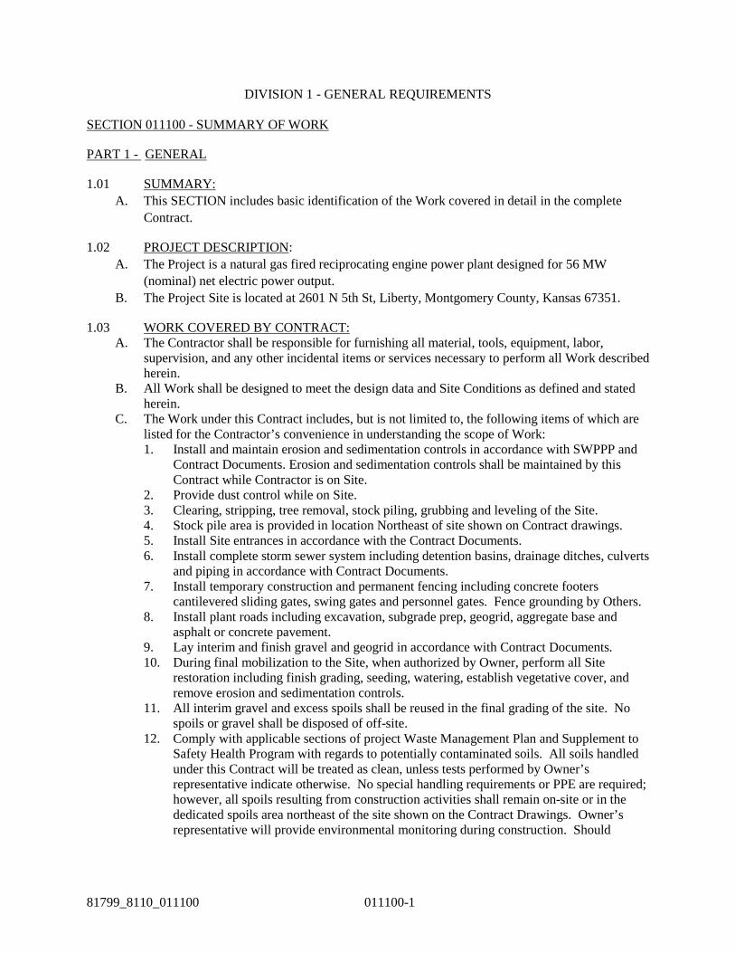
DIVISION 1 - GENERAL REQUIREMENTS SECTION 011100 - SUMMARY OF WORK
PART 1 - GENERAL
1.01 SUMMARY: A. This SECTION includes basic identification of the Work covered in detail in the complete
Contract.
1.02 PROJECT DESCRIPTION: A. The Project is a natural gas fired reciprocating engine power plant designed for 56 MW
(nominal) net electric power output. B. The Project Site is located at 2601 N 5th St, Liberty, Montgomery County, Kansas 67351.
1.03 WORK COVERED BY CONTRACT: A. The Contractor shall be responsible for furnishing all material, tools, equipment, labor,
supervision, and any other incidental items or services necessary to perform all Work described herein.
B. All Work shall be designed to meet the design data and Site Conditions as defined and stated herein.
C. The Work under this Contract includes, but is not limited to, the following items of which are listed for the Contractor’s convenience in understanding the scope of Work: 1. Install and maintain erosion and sedimentation controls in accordance with SWPPP and
Contract Documents. Erosion and sedimentation controls shall be maintained by this Contract while Contractor is on Site.
2. Provide dust control while on Site. 3. Clearing, stripping, tree removal, stock piling, grubbing and leveling of the Site. 4. Stock pile area is provided in location Northeast of site shown on Contract drawings. 5. Install Site entrances in accordance with the Contract Documents. 6. Install complete storm sewer system including detention basins, drainage ditches, culverts
and piping in accordance with Contract Documents. 7. Install temporary construction and permanent fencing including concrete footers
cantilevered sliding gates, swing gates and personnel gates. Fence grounding by Others. 8. Install plant roads including excavation, subgrade prep, geogrid, aggregate base and
asphalt or concrete pavement. 9. Lay interim and finish gravel and geogrid in accordance with Contract Documents. 10. During final mobilization to the Site, when authorized by Owner, perform all Site
restoration including finish grading, seeding, watering, establish vegetative cover, and remove erosion and sedimentation controls.
11. All interim gravel and excess spoils shall be reused in the final grading of the site. No spoils or gravel shall be disposed of off-site.
12. Comply with applicable sections of project Waste Management Plan and Supplement to Safety Health Program with regards to potentially contaminated soils. All soils handled under this Contract will be treated as clean, unless tests performed by Owner’s representative indicate otherwise. No special handling requirements or PPE are required; however, all spoils resulting from construction activities shall remain on-site or in the dedicated spoils area northeast of the site shown on the Contract Drawings. Owner’s representative will provide environmental monitoring during construction. Should

SECTION 011100 - SUMMARY OF WORK: continued
011100-2 81799_8110_011100
contaminated soils or groundwater associated with Contractor’s work be detected, the contract will be adjusted accordingly.
1.04 WORK BY OTHERS: A. Contract C4310 – Pre Engineered Metal Building: Provides and installs building steel, walls,
roof, panels, masonry walls, insulation, interior finishes, doors, door hardware, plumbing and fixtures, toilet accessories, air handling units, ventilation fans and HVAC ducting. Installs engine hall ventilation fans. This contractor will pour the concrete ceiling cap in the administration building conference room, electrical room and communications room.
B. Contract C8220 – Foundations and Underground Utilities Installation: Excavates, prepares subgrade, lays structural fill and installs all foundations for buildings and slabs on grade. Trenches and installs all duct bank and underground piping including domestic water, waste water, and gas systems. Installs underground grounding grid.
C. Contract C8320 – Mechanical Installation: Installs all above ground mechanical process piping, piping specials, equipment, and instrumentation. Sets all mechanical equipment and structural steel in the yard of the power plant. Installs all steel in the engine hall supporting engine auxiliary equipment. Supplies and installs fire protection and detection system.
D. Contract C8410 – Electrical Installation: Installs all electrical wiring, cable tray, and electrical equipment. Connects equipment, steel and fencing to the Contractor provided below ground grounding grid. Installs roadway light pole foundations, buried conduit for roadway lighting and light poles.
E. Contract C8440 – Above Ground Substation Installation: Installs substation equipment, steel, dead end structure, lighting, fencing and wiring.
F. Contract C9055 – Materials Testing: Third party construction services and material testing including but not limited to compaction, density, moisture, concrete and concrete paving testing.
G. Contract C1210 – Reciprocating Engines: Supply and Install by Others.

SECTION 011100 - SUMMARY OF WORK: continued
81799_8110_011100 011100-3
1.05 PROJECT PHASING A. Based on construction sequencing, Work under this contract shall occur in two phases
described below, each phase will require its own, separate mobilzation: B. PHASE 1
1. Install erosion and sediment controls. 2. Clear, grub, and rough grade entire site. 3. Top soil should be stripped to a minimum of 12” and stock piled Northeast of the site. 4. Install fencing as shown CS106– Interim Site Restoration Plan. 5. Prepare construction parking, trailer area and main construction laydown at Southeast
corner of the site. 6. Grade site access points and prepare road base so vehicles can access the site. 7. Install Storm Sewer System. 8. Prepare all remaining gravel areas shown on CS106 – Interim Site Restoration Plan. 9. Install heavy haul road, including first lift of asphalt on loop road section. 10. Install road base all other plant roads.
C. PHASE 2 1. Remove temporary construction gravel and geogrid in accordance with CS106 – Final
Restoration Plan. 2. Utilize temporary construction gravel and stock piled topsoil to bring site to final grade.
Restore any grading damaged by construction activities. All interim gravel and excess spoils shall be reused in the final grading of the site. No spoils or gravel shall be disposed of off site.
3. Seed site as required by the Contract Documents. 4. Install fencing as show on CS107– Final Restoration and the Contract Documents. 5. Install plant roads as shown on CS107– Final Restoration and the Contract Documents. 6. Remove erosion and sediment controls.
1.06 CODES AND STANDARDS A. Design specifications and construction of the Project shall be in accordance with (1) applicable
laws, regulations, codes and standards of the Federal Government and State of Kansas, including those set forth below and, (2) applicable local (including county and city) laws, regulations, codes and ordinances, including those set forth below. Publications from the following nationally recognized organizations are applicable to the engineering, design, manufacture, and testing of the Equipment included in the Specifications to the extent referenced in these Specifications. All references to publications are to the latest issue of each together with all latest addenda, amendments, or additions thereto as of the Effective Date. References shall be made in accordance with the abbreviations listed below. In the event that conflicts arise between the codes, standards of practice, specifications or manufacturer recommendations described herein and codes, laws, rules, decrees, regulations, standards, etc., of the locality where the equipment is to be installed, the more stringent code shall apply. Supplier shall provide a written position of any such conflict clarifications to Owner in writing.
B. Federal Codes:

SECTION 011100 - SUMMARY OF WORK: continued
011100-4 81799_8110_011100
CAAA Clean Air Act and Amendments CFR Code of Federal Regulations FERC Federal Energy Regulatory Commission NERC North American Electric Reliability Corporation Title 29 Code of Federal Regulations (CFR), Part 1910 Occupational
Safety and Health Standards.
C. Industry Codes:
AA Aluminum Association AASHTO American Association of State Highway and Transportation
Officials ACI American Concrete Institute 318-08 ACI Building Code Requirements for Masonry Structures 530-05 AFPA American Forest and Paper Association AGA American Gas Association AIA American Institute of Architects AISC American Institute for Steel Construction, ASD/LRFD (13th Ed.) AISI American Iron and Steel Institute ANSI American National Standards Institute API American Petroleum Institute ASCE American Society of Civil Engineers 7-05 ASHRAE American Society of Heating, Refrigeration and Air Conditioning ASME American Society of Mechanical Engineers ASTM American Society for Testing and Materials ASNT American Society of Nondestructive Testing AWWA American Water Works Association AWS American Welding Society CRSI Concrete Reinforcing Steel Institute DIN German Standard (Deutsche Institute für Normung) EJMA Expansion Joint Manufacturer’s Association EN European Standard FCI Fluid Control Institute HEI Heat Exchange Institute HI Hydraulic Institute IAPWS International Association for the Properties of Water and Steam IBC International Building Code 2009 ICEA Insulated Cable Engineers Association IEEE Institute of Electrical and Electronics Engineers IES IES Lighting Handbook ISA International Society of Automation ISO International Standard Organization MSS Manufacturers Standardization Society NEC National Electrical Code NEMA National Electrical Manufacturers Association NESC National Electric Safety Code NFPA National Fire Protection Association

SECTION 011100 - SUMMARY OF WORK: continued
81799_8110_011100 011100-5
SMACNA Sheet Metal and Air Conditioner Contractors National Association SSPC Steel Structures Painting Council TEMA UFC Thermal Insulation Manufacturers Association UL Underwriters Laboratories
D. County / City Codes:
Fire Marshall / AHJ 2009 International Fire Code Building Code 2009 International Building Code
1.07 PROJECT SITE CONDITIONS: A. The Project Site has the following Site Conditions:
1. Plant elevation is 755 feet above mean sea level. 2. Indoor Design Temperatures – Engine Halls, Mechanical Rooms
a. Maximum Dry Bulb 120°F b. Minimum Dry Bulb 50°F
3. Outdoor Design Temperatures (2009 ASHRAE) a. Maximum Dry Bulb (1%) 97.1°F b. Mean Coincident Wet Bulb (1%) 75.8°F c. Minimum Dry Bulb (99.6%) 10.3°F
4. Outdoor Extreme Design Temperatures (2009 ASHRAE) a. Maximum Dry Bulb (n = 1 years) 102.8°F b. Minimum Dry Bulb (n = 1 years) 0.6°F c. Extreme Max Wet Bulb 88.9°F
B. IBC Design Criteria: 1. Occupancy Category: III 2. Wind loads – Section 1609
a. Basic wind speed: V3S = 90 mph b. Exposure category: C c. Wind Importance Factor: Iw=1.15 d. Minimum lateral pressure: ps = 10 psf
3. Seismic loads – Section 1613 a. Seismic Site Class: D b. Seismic Importance Factor: IE=1.25 c. Component Importance Factor: IP = 1.0
(per ASCE 7-05 Section 13.1) d. Design Spectral Response Acceleration
(1) Short Period: Ss = 0.193 (2) 1 Second: S1 = 0.063 (3) Max. considered short period: SMS = 0.309 (4) Max. considered 1-second: SM1 = 0.151 (5) 5% damped design short period: SDS = 0.206 (6) 5% damped design 1-second: SD1 = 0.101 (7) Long-Period Transition Period: TL = 12 seconds
e. Seismic Design Category: B

SECTION 011100 - SUMMARY OF WORK: continued
011100-6 81799_8110_011100
4. Snow loads – Section 1608: a. Snow Importance Factor: IS = 1.1 b. Ground snow load: pg = 15 psf c. Terrain Category: C
5. Ice Loads a. Ice thickness Importance Factor: Ii = 1.25 b. Wind Concurrent with ice Importance Factor
IW = 1.0 c. Nominal Ice Thickness: t = 1.0” d. Concurrent wind speed VC = 40mph
C. Precipitation 1. Minimum Annual: Unknown 2. Average Annual: 37 inches 3. Maximum Annual: Unknown 4. Maximum 25-year 24 Hour Rain: 8 inches 5. Maximum 24 Hour Snow: 13 inches
D. Prevailing Wind Direction 1. Annual: South
1.08 SITE UTILITIES: A. Mechanical:
1. Water B. Electrical:
PART 2 - PRODUCTS - Not Applicable.
PART 3 - EXECUTION - Not Applicable.
END OF SECTION 011100

01 25 00 - 1
81799_012500 01/22/2002
SECTION 01 25 00 - SUBSTITUTIONS
PART 1 - GENERAL
1.01 SUMMARY: A. This Section includes administrative and procedural requirements for handling requests for
substitutions made after award of the Contract.
1.02 RELATED REQUIREMENTS: A. Requirements for submitting Contractor's construction progress schedule and the Submittal
schedule: SECTIONS 01 32 00 and 01 33 00. B. Requirements governing Contractor's selection of products: SECTION 01 60 00.
1.03 DEFINITIONS: A. Definitions in this Article do not change or modify the meaning of other terms used in the
Contract Documents. B. Substitutions: Changes in products, Materials, Equipment, and methods of construction
required by the Contract Documents proposed by the Contractor after award of the Contract are considered to be requests for substitutions. The following are not considered to be requests for substitutions: 1. Revisions to the Contract Documents requested by Owner or Engineer. 2. Specified options of products and construction methods included in the Contract
Documents. 3. Substitutions requested during the bidding period, and accepted by Addendum prior to
award of the Contract, are included in the Contract Documents and are not subject to requirements specified in this Section for substitutions.
1.04 SUBMITTALS: A. Substitution Request Submittal: Engineer will consider written requests for substitution if
received within 60 days after commencement of the Work. Requests received more than 60 days after commencement of the Work may be considered or rejected at the discretion of Engineer. 1. Submit 3 copies of each request for substitution for consideration. Submit requests in the
form and according to procedures required for Change Order proposals. Requests for substitution shall not be submitted in the form of a Request for Information (RFI).
2. Identify the Equipment or Material, the fabrication, or installation method to be replaced in each request. Include related Specification Section/Article and Drawing numbers.
3. Provide complete documentation showing compliance with the requirements for substitutions, and the following information, as appropriate: a. Statement indicating why specified product or method of construction cannot be
provided. b. Coordination information, including a list of changes or modifications needed to
other parts of the Work and to construction performed by Owner and separate contractors, that will be necessary to accommodate the proposed substitution.
c. A detailed comparison of significant qualities of the proposed substitution with those of the Work specified. Significant qualities may include elements such as performance, weight, size, durability, visual effect, and specific features and requirements indicated.
d. Product data, including drawings and descriptions of products and fabrication and installation procedures.
e. Samples, where applicable or requested.

SECTION 01 25 00 - SUBSTITUTIONS: continued
01 25 00 - 2
01/22/2002 81799_012500
f. Identification of available sales, maintenance, repair, and replacement services. g. A statement indicating the effect of the substitution on Contractor's construction
progress schedule compared to the schedule without approval of the substitution. Indicate the effect of the proposed substitution on the overall Contract Times. If specified product cannot be provided within the Contract Times, provide letter from manufacturer, on manufacturer's letterhead, stating lack of availability or delay in delivery.
h. An itemized estimate of costs that will result directly or indirectly from approval of the substitution, including: (1) A proposal of the net change, if any, in the Contract Price. (2) Costs of redesign required by the proposed change. (3) Costs of resulting claims as determined in coordination with other contractors
having work on the Project affected by the substitution. i. Statement indicating whether or not incorporation or use of the substitute is subject
to payment of any license fee or royalty. j. Contractor's certification that the proposed substitution conforms to requirements in
the Contract Documents, will perform adequately the functions and achieve the results called for by the general design, is similar in substance to that specified, and is suitable for same use as that indicated and specified.
k. Contractor's waiver of rights to additional payment or time that may subsequently become necessary because of the failure of the substitution to perform adequately.
4. Engineer’s Action: If necessary, Engineer will request additional information or documentation for evaluation within two weeks of receipt of a request for substitution. Engineer will notify Contractor of acceptance or rejection of the substitution within 2 weeks of receipt of the request, or one week of receipt of additional information or documentation, whichever is later. Acceptance will be in the form of a Change Order.
PART 2 - PRODUCTS
2.01 SUBSTITUTIONS: A. Conditions: Engineer will receive and consider Contractor's request for substitution when one
or more of the following conditions are satisfied, as determined by Engineer. If the following conditions are not satisfied, Engineer will return the requests without action except to record noncompliance with these requirements. 1. Extensive revisions to the Contract Documents are not required. 2. Proposed substitution is in keeping with the general intent of the Contract Documents and
will produce indicated results. 3. Substitution request is timely, fully documented, and properly submitted. 4. The specified product or method of construction cannot be provided within the Contract
Times. Engineer will not consider the request if the product or method cannot be provided as a result of failure to pursue the Work promptly or coordinate activities properly.
5. The requested substitution offers Owner a substantial advantage, in cost, time, energy conservation, or other considerations, after deducting additional responsibilities Owner must assume. Owner's additional responsibilities may include compensation to Engineer for redesign and evaluation services, increased cost of other construction by Owner, and similar considerations.
6. The specified product or method of construction cannot receive necessary approval by a governing authority, and the requested substitution can be approved.
SECTION 012500 - SUBSTITUTIONS: continued
01 25 00 - 3
81799_012500 01/22/2002
7. The specified product or method of construction cannot be provided in a manner that is compatible with other materials and where Contractor certifies that the substitution will overcome the incompatibility.
8. The specified product or method of construction cannot be coordinated with other materials and where Contractor certifies that the proposed substitution can be coordinated.
9. The specified product or method of construction cannot provide a warranty required by the Contract Documents and where Contractor certifies that the proposed substitution provides the required warranty.
10. Where a proposed substitution involves more than one prime contractor, each contractor shall cooperate with the other contractors involved to coordinate the Work, provide uniformity and consistency, and assure compatibility of products.
B. Engineer’s review and acceptance of Submittals shall not relieve Contractor from responsibility for any variation from the requirements of the Contract Documents. Engineer’s acceptance of Submittals not complying with the Contract Documents does not constitute an acceptable or valid request for substitution, nor does it constitute approval of a substitute. Acceptance by Engineer shall not relieve Contractor from responsibility for errors or omissions in the Submittals.
PART 3 - EXECUTION (NOT APPLICABLE)
END OF SECTION 01 25 00

81799_013100 013100-1
SECTION 013100 - PROJECT COORDINATION AND MEETINGS
PART 1 - GENERAL
1.01 SUMMARY: A. This Section includes administrative provisions for coordinating construction operations on the
Project including, but not limited to, the following: 1. Coordination drawings. 2. Project meetings. 3. Requests For Information (RFIs). 4. Coordination of Contractor(s) on-Site.
B. Each Contractor shall participate in coordination requirements. Certain areas of responsibility will be assigned to a specific Contractor.
C. Related Work Specified Elsewhere: 1. For preparing and submitting Contractor's construction progress schedule: SECTION
013200. 2. For Submittal Requirements: SECTION 013300. 3. For coordinating closeout of the Contract: SECTION 017800.
1.02 DEFINITIONS: A. RFI: Request For Information prepared by Contractor and submitted to Engineer seeking
interpretation or clarification of the Contract Documents.
1.03 COORDINATION: A. Coordination: Each Contractor shall coordinate its construction operations with those of other
Contractors, Owner, and other entities to ensure efficient and orderly installation of each part of the Work. Each Contractor shall coordinate its operations with operations, included in different Sections, that depend on each other for proper installation, connection, and operation. 1. Schedule construction operations in sequence required to obtain the best results where
installation of one part of the Work depends on installation of other components, before or after its own installation.
2. Coordinate installation of different components with other Contractors to allow optimum accessibility for required maintenance, service, and repair.
3. Make adequate provisions to accommodate items scheduled for later installation. 4. Where availability of space is limited, coordinate installation of different components to
allow optimum performance and accessibility for required maintenance, service, and repair of all components, including mechanical and electrical.
B. Prepare memoranda for distribution to each party involved, outlining special procedures required for coordination. Include such items as required notices, reports, and list of attendees at meetings. 1. Prepare similar memoranda for Owner and separate Contractors if coordination of their
Work is required. C. Administrative Procedures: Coordinate scheduling and timing of required administrative
procedures with other construction activities and activities of others to avoid conflicts and to ensure orderly progress of the Work. Such administrative activities include, but are not limited to, the following: 1. Preparation of construction progress schedule. 2. Preparation of the schedule of values. 3. Provide quantities and man hours for Field Progress Measurement System (FPMS) 4. Installation and removal of temporary facilities and controls.

SECTION 013100 - PROJECT COORDINATION AND MEETINGS: continued
013100-2 81799_013100
5. Delivery and processing of Submittals. 6. Progress meetings. 7. Preinstallation conferences. 8. Project closeout activities. 9. Startup and adjustment of systems. 10. Project closeout activities.
1.04 SUBMITTALS: NOT USED
1.05 PROJECT MEETINGS: A. Not Used B. Preconstruction Conference:
1. Engineer will conduct a meeting prior to Contractor mobilization, to review items stated in the following agenda and to establish a working understanding between the parties as to their relationships during performance of the Work of Site.
2. Preconstruction conference shall be attended by: a. Representative(s) of Contractor including Contractor’s superintendent. b. Engineer. c. Representative(s) of Owner. d. At Engineer or Owner's option, representatives of principal Subcontractors and
Suppliers. 3. Meeting Agenda:
a. Construction schedules. b. Phasing. c. Critical Work sequencing and long-lead items. d. Designation of key personnel and their duties; lines of communication. e. Project coordination. f. Procedures and Processing of:
(1) RFIs. (2) Field decisions. (3) Substitutions. (4) Submittals. (5) Change Orders. (6) Applications for Payment.
g. Procedures for testing. h. Procedures for preparing and maintaining record documents. i. Use of Premises:
(1) Office, Work, storage, laydown, and parking areas. (2) Owner's requirements. (3) Work restrictions and hours.
j. Construction facilities, controls, and construction aids. k. Temporary utilities. l. Safety and first-aid. m. Deliveries of Equipment and Materials.
4. Location of Meeting: At the Project Site or as directed by Engineer. 5. Reporting:
a. Within 5 working Days after the meeting, Engineer will prepare and distribute minutes of the meeting to Owner and Contractor.
b. Contractor shall provide copies to Subcontractors and major Suppliers.

SECTION 01310 - PROJECT COORDINATION AND MEETINGS: continued
81799_013100 013100-3
C. Coordination Schedules: 1. Engineer will conduct a meeting at least 10 Days before submission of the first
Application for Payment to finalize the initial coordination schedules requested under SECTION 013200 - CONSTRUCTION PROGRESS SCHEDULES AND REPORTS.
2. The meeting shall be attended by: a. Representative(s) of Contractor including Contractor’s superintendent (and
scheduler). b. At Engineer or Owner's option, representatives of principal Subcontractors and
Suppliers. c. Engineer and Resident Project Representative. d. Representative(s) of Owner.
D. Construction Progress Meetings: 1. Engineer will schedule and conduct a meeting at least weekly and at other times
requested by Engineer. Representatives of the Engineer, and Contractor shall be present at each meeting. With Engineer's concurrence, Contractor may request attendance by representatives of Subcontractors, Suppliers, or other entities concerned with current program or involved with planning, coordination, or performance of future activities. All participants in the meeting shall be familiar with the Project and authorized to conclude matters relating to the Work.
2. Contractor and each Subcontractor represented shall be prepared to discuss the current construction progress report and any anticipated future changes to the schedule. Each Subcontractor shall comment on the schedules of Contractor and other Subcontractors and advise if their current progress or anticipated activities are compatible with that Subcontractor's Work.
3. If one Subcontractor is delaying another, Contractor shall issue such directions as are necessary to resolve the situation and promote construction progress.
4. Meeting Agenda: a. Review of construction progress since previous meeting. b. Field observations, interface requirements, conflicts. c. Issues which may impede construction schedule. d. Off-Site fabrication. e. Delivery schedules. f. Submittal schedules and status. g. Site use; coordination with other Contractors. h. Temporary facilities, controls, and services. i. Hours of Work. j. Hazards and risks. k. Housekeeping. l. Quality and Work standards. m. RFIs. n. Status of Change Orders. o. Documentation of information for payment requests. p. Corrective measures and procedures to regain construction schedule if necessary. q. Revisions to construction schedule. r. Review of proposed activities for succeeding Work period. s. Review proposed Contract modifications for:
(1) Effect on construction schedule and on completion date. (2) Effect on other Contracts of the Project.
t. Other business.

SECTION 013100 - PROJECT COORDINATION AND MEETINGS: continued
013100-4 81799_013100
5. Location of Meetings: At Project Site. 6. Reporting:
a. Within 3 working Days after each meeting, Engineer will prepare and distribute minutes of the meeting to Owner and Contractor.
b. Contractor shall distribute copies to principal Subcontractors and Suppliers. E. Preinstallation Conferences:
1. Contractor shall conduct a preinstallation conference at the Project Site before each construction activity that requires coordination with other construction and where required in DIVISIONS 2 through 48.
2. Engineer, Contractor and representatives of manufacturers and fabricators, of products furnished by this Contract or by others, involved in or affected by the installation Work and its coordination or integration with other Materials and installations, shall attend the meeting.
3. Review the progress of other construction activities and preparations for the particular activity under consideration at each preinstallation conference, including installation procedures and requirements for the following: a. Contract Documents. b. Options. c. Related Change Orders. d. Purchases. e. Deliveries. f. Shop Drawings, product data, and quality control Samples. g. Review of mockups. h. Possible conflicts. i. Compatibility problems. j. Time schedules. k. Weather limitations. l. Manufacturer's recommendations. m. Warranty requirements. n. Acceptability of substrates. o. Temporary facilities and controls. p. Space and access limitations. q. Governing regulations. r. Safety. s. Inspecting and testing requirements. t. Required performance results. u. Recording requirements. v. Protection of construction, personnel, and adjacent Work.
4. Record significant discussions and agreements and disagreements of each conference. Contractor shall distribute the minutes of the meeting within 3working Days after the meeting to everyone concerned, including Owner and Engineer.
5. Do not proceed with the installation if disagreements arise during the conference which cannot be successfully resolved at the time. Contractor shall take actions necessary to resolve impediments to performance of Work and reconvene the conference at the earliest feasible date.
F. Not Used. G. Startup Coordination Meetings:
1. Engineer will conduct weekly (or as required to meet project needs) startup coordination meetings to be attended by Owner’s representative(s) and Contractors at the Site.
SECTION 01310 - PROJECT COORDINATION AND MEETINGS: continued
81799_013100 013100-5
Contractor shall participate in such conferences, accompanied by Subcontractors as requested by Engineer.
2. Agenda will be discussion of daily startup tasks and labor needs. 3. Location of Meetings: (At the Project Site).
1.06 REQUESTS FOR INFORMATION (RFIs): A. Procedure: Promptly on discovery of the need for interpretation of the Contract Documents,
and if not possible to request interpretation at Project meeting, prepare and submit an RFI with the content specified. 1. RFIs shall originate with Contractor. RFIs submitted by entities other than Contractor
will be returned with no response. 2. Coordinate and submit RFIs in a prompt manner so as to avoid delays in Contractor's
Work or Work of Subcontractors. 3. RFIs shall be submitted via Burns & McDonnell WebTools application.
B. Content of the RFI: Include a detailed, legible description of item needing interpretation and the following: 1. Project name. 2. Date. 3. Name of Contractor. 4. Contract number and title. 5. Name of Engineer. 6. RFI number, numbered sequentially. 7. Specification Section number and title and related paragraphs, as appropriate. 8. Drawing number and detail references, as appropriate. 9. Field dimensions and conditions, as appropriate. 10. Contractor's suggested solution(s). If Contractor's solution(s) impact the Contract Times
or the Contract Price, Contractor shall state impact in the RFI. 11. Contractor's signature. 12. Attachments: Include drawings, descriptions, measurements, photos, product data, Shop
Drawings, and other information necessary to fully describe items needing interpretation. C. Software-Generated RFIs: Software-generated form with substantially the same content as
indicated above. 1. Attachments shall be electronic files in Adobe Acrobat PDF format.
D. Engineer's Action: Engineer will review each RFI, determine action required, and return it. Allow 5 working Days for Engineer's response for each RFI. RFIs received after 1:00 p.m. local time will be considered as received the following working Day. 1. The following RFIs will be returned without action:
a. Requests for approval of Submittals. b. Requests for approval of substitutions. c. Requests for coordination information already indicated in the Contract Documents. d. Requests for adjustments in the Contract Times or the Contract Price. e. Requests for interpretation of Engineer's actions on Submittals. f. Incomplete RFIs or RFIs with numerous errors.
2. Multiple RFIs addressing similar or identical issues may be addressed by Engineer with a single broad response.
3. Engineer's action may include a request for additional information, in which case Engineer's time for response will start again upon Contractor's response and resubmittal.
4. If Contractor believes the RFI response warrants change in the Contract Times or the Contract Price, notify Engineer in writing within 5 Days of receipt of the RFI response.

SECTION 013100 - PROJECT COORDINATION AND MEETINGS: continued
013100-6 81799_013100
E. On receipt of Engineer's action, update the RFI log and promptly distribute the RFI response to affected parties. Review response and notify Engineer within 5 Days if Contractor disagrees with response. 1. RFI Log: Resident Project Representative will maintain RFI log.
PART 2 - PRODUCTS - Not Applicable.
PART 3 - EXECUTION - Not Applicable. END OF SECTION 013100

81799_013200 013200-1
SECTION 013200 - CONSTRUCTION PROGRESS SCHEDULES AND REPORTS
PART 1 - GENERAL
1.01 SUMMARY: A. This Section includes administrative and procedural requirements for documenting the
progress of construction during performance of the Work, including the following: 1. Preliminary construction progress schedule. 2. Construction progress schedule. 3. Schedule of Submittals. 4. Schedule of values. 5. Construction progress reports. 6. Daily construction reports. 7. Equipment and Material location reports. 8. Field condition reports. 9. Special reports.
B. Related Work Specified Elsewhere: 1. For submitting and distributing meeting and conference minutes: SECTION 013105 -
PROJECT COORDINATION AND MEETINGS. 2. For submitting schedules and reports: SECTION 013305 - SUBMITTALS.
1.02 DEFINITIONS: A. Float: The measure of leeway in starting and completing an activity.
1. Float available in the schedule, at any time shall not be considered for the exclusive use of either the Engineer or the Contractor. During the course of contract execution, any float generated due to the efficiencies of either party is not for the sole use of the party generating the float; rather it is a shared commodity to be reasonably used by either party. A schedule showing work completing in less time than the Contract time, and accepted by the Engineer, will be considered to have Project Float. Project Float will be a resource available to both the Engineer and the Contractor. No time extensions will be granted nor delay damages paid unless a delay occurs which impacts the Project's critical path, consumes all available float or contingency time, and extends the work beyond the Contract Completion Date. Contractor shall not use artificial activity durations, preferential logic, or other devices for sequestering float. Engineer retains the right to reject any schedule submittal in which Contractor has sequestered float.
2. Free float is the amount of time an activity can be delayed without adversely affecting the early start of the successor activity.
3. Total float is the measure of leeway in starting or completing an activity without adversely affecting an intermediate deadline or the planned Contract completion date.
B. Milestone: A key or critical point in time for reference or measurement. A milestone has no duration.
C. Time Scaled Logic Diagram: A bar chart diagram of a network schedule, showing activities and activity relationships.
D. Resource Loading: The allocation of manpower, quantities or equipment necessary for the completion of an activity as scheduled.
E. Activity Percent Complete – Physical percent compete of an activity as determined by a consensus of a subjective evaluation between contactor and Engineer

SECTION 013200 - CONSTRUCTION PROGRESS SCHEDULES AND REPORTS: continued
013200-2 81799_013200
F. Contractor Caused Delays: Shortage of manpower, or late delivery by Contractor’s material or equipment suppliers, shall not be considered cause for delay in completion. If the schedule deficiency occurs through no fault of Engineer, any costs incurred by Contractor to implement and maintain the recovery schedule shall be to Contractor’s account.
1.03 SUBMITTALS: A. Qualification Data: For scheduling consultant. B. Schedule of Submittals: Per SECTION 013300-APPENDIX A. C. Preliminary Construction Progress Schedule: Submit in specified electronic format per
SECTION 013300 SUBMITTALS . D. Construction Progress Schedule: Contractor’s Baseline schedule and all updates of the
Detailed Construction Schedule shall:
1. Contractor shall submit for Engineer approval, within seven (7) calendar days of the prescheduling conference, a preliminary schedule defining Contractor’s planned operations for the first sixty (60) calendar days.
2. Contractor shall submit for Engineer approval, within thirty (30) days of the prescheduling conference, a Critical Path Method (CPM) project schedule showing the sequence and the due date of data Submittals, Engineer approvals, procurement, fabrication, contractual milestones, and all construction activities to coincide with the Schedule of Work.
3. The project schedule shall include an appropriate level of detail. Contractor submissions shall follow the direction of Engineer regarding reasonable activity durations. Reasonable durations are those that allow the progress of activities to be accurately determined between update periods (usually all non-procurement activities' Original Durations are less than the total workdays between two update periods). Durations shall be in workdays. Contractor's scheduler should develop the proper calendars in the scheduling software, based on the proposed weekly work schedule and planned holidays (5-day, 6-day, 7-day, etc).
4. Contractor shall update the submitted Schedule on a weekly basis in preparation for the Construction Progress Meetings or as otherwise directed by Engineer. The weekly progress report will be issued to Engineer, in the approved electronic format, by 8:00 am the business day prior to the weekly Construction Progress Meeting.
5. Contractor shall submit an update of Contractor’s complete schedule with the monthly Application for Payment. The status date of the schedule and activity progress therein will coincide with the progress payments requested in the Application for Payment. Receipt of the Schedule by Engineer shall be a condition precedent to processing and paying Applications for Payment.
6. Engineer intends to use Primavera P6 software for the integrated project schedule. Other scheduling software or manual methods used by Contractor to produce required information shall require approval by Engineer. All schedules prepared with Primavera P6 software shall be configured to calculate data as follows:
a. Contiguous scheduling.
SECTION 013200 - CONSTRUCTION PROGRESS SCHEDULES AND REPORTS: continued
013200-3 81799_013200
b. Total float calculations based upon finish dates.
c. Retained logic.
d. Start-to-start lags calculated from actual start dates.
e. Percent complete and remaining duration not linked.
7. Cost Loading Activities: In compliance with the contract cost breakdown represented by the Contract Schedule of Values, the project schedule will be loaded with costs. Costs for submittal preparation will be assigned to the respective submittal milestone(s). Equipment costs will be assigned to their respective Procurement Activities (i.e., the delivery milestone activity). Costs for installation of the material/equipment (labor, construction equipment, and temporary materials) will be assigned to their respective Construction Activities. The value of inspection/testing activities will not be less than 10 percent of the total costs for Procurement and Construction Activities. Evenly disperse overhead and profit to each activity over the duration of the project. The total of all cost loaded activities; including costs for material and equipment delivered for installation on the project, and labor and construction equipment loaded construction activities, shall total to 100 percent of the value of the contract
8. Be work hour loaded by activity. Have an account code assigned to each activity and produce percent complete progress curves based on work hours extracted by account code.
9. Resource load activities with quantities so as to provide Quantity Curves prior to the start of work. These curves are to reflect planned installed quantities in accordance with Contractor’s Detailed Construction Schedule. All major commodities should be addressed, including but not limited to: Concrete (CY), LB Pipe (LF), SB Pipe (LF), Structural Steel (TN), Cable Tray (LF), Conduit (LF), Cable (LF), Terminations (EA), Loop Checks (EA), Hydrotests (EA), etc. On a weekly basis Contractor shall submit to Engineer actual installed quantities for each of the Quantity Curves.
10. Provide a Systems Turnover Schedule in accordance with Engineer’s defined systems. As bulk installation nears completion, approx 60% to 75% construction complete, Contractor shall develop a Systems Turnover Schedule for the Work to-go.
11. Utilize the Critical Path Method (CPM) with predecessor/successor relationships defined.
12. Include all interferences and impacts to Contractor’s Work.
13. Display all major milestones for completion of Work as defined in the Contract Documents.
14. Contain all activities required to be completed by others in order for Engineer to complete the Work as defined in the Contract Documents.
15. Include the total Scope of Work, whether performed directly by Contractor, or contracted to a third party.
SECTION 013200 - CONSTRUCTION PROGRESS SCHEDULES AND REPORTS: continued
013200-4 81799_013200
16. Display the Baseline schedule as a thin solid black bar under the current bar. E. Schedule Reports: Concurrent with CPM schedule, submit copy of each of the following
computer-generated reports. 1. Bar Chart or Time Scaled Logic Diagram: All printed updates of the schedule will be in
the form of a bar-chart containing the following information: Activity ID, Activity Description, Original Duration, Remaining Duration, Percent Complete, Planned/Actual Start Date, Planned/Actual Finish Date, Late Start Date, Late Finish Date, Planned/Actual Finish Date variance to Baseline Planned Finish Date and Total Float. The original approved schedule shall be referenced as the “Baseline” schedule. All printed update submittals of the schedule shall reflect the Baseline schedule planned start and finish dates for like activities as target bars represented as solid thin black bars below the current bar. Open-ended activities and artificial constraint dates shall be minimized. Mandatory constraint dates and hammock activities may only be used with Engineer approval.
2. Earnings Report: A compilation of total earnings on the project from the sooner of the Notice to Proceed, Contract award or commencement of the Work to the most recent monthly progress payment request. Include a column for the difference between the previous request amount and the current payment request amount. Sort report first by Schedule of Values category and then by activity.
3. Critical Path Report: All activities with float values of less than ten (10) work days are considered critical. In this report all critical activities will be grouped by total float and then their independent logical path ending with the appropriate contractual completion milestone or tie to a longer path. They will be sorted by early start, early finish and activity ID within the activities flowing from upper left to lower right on the page. Display relationship lines.
4. Log Report: With each updated schedule submission, provide a computer generated Log Report using a recognized schedule comparison software listing all changes made between the previous schedule and current updated schedule. Identify the name of the previous schedule and name of the current schedule being compared. This report will as a minimum show changes for: Added & Deleted Activities, Original Durations, Remaining Durations, Activity Percent Complete, Total Float, Free Float, Calendars, Descriptions, Constraints (added, deleted or changed), Actual Starts/Finishes, Added/Deleted Resources, Resource Quantities, Costs, Added/Deleted Relations, Changed Relation Lags, Changed Driving Relations, and Changed Critical Status.
F. Contractor’s Three-Week Lookahead Schedule: Shall be issued to Engineer on a weekly basis, be manpower loaded, and indicate all planned Work to be accomplished during the current week and the next two (2) week period in support of and in accordance with Contractor’s Detailed Construction Schedule. Planned and actual activities shall also be indicated for the previous week. Any activities that are required to be accomplished by Others that would impact and/or prevent Contractor from starting and/or accomplishing its planned Work shall also be displayed. The level of detail shall be sufficient to direct the efforts of the craft on a day to day basis.
G. Field Progress Measurement System (FPMS): 1. The detailed breakdown for the FPMS will be in accordance with Engineer’s Code of
Accounts. Along with the proper Account Code, each item of the breakdown must have assigned an estimated quantity and estimated manhours. As additional scope is identified and added to the Work, Contractor shall provide detailed breakdowns in the same manner. Within each account, the breakdown shall be detailed enough to allow installed quantities (i.e., cy, lf, each, etc.) to be physically verifiable, and to allow status

SECTION 013200 - CONSTRUCTION PROGRESS SCHEDULES AND REPORTS: continued
013200-5 81799_013200
availability for testing and system turnover. Engineer’s Code of Accounts is included in SECTION 013200 Appendix B – Construction Field Progress Measurement System.
2. On a weekly basis Contractor shall submit to Engineer a status of the quantities installed for each activity in 013200 Appendix B – Construction Field Progress Measurement System, and actual manhours spent. Activities partially complete will be reportable by Contractor utilizing the Partial Credit Guidelines (attached within Appendix A). Appendix A-Partial Credit Guidelines represent draft conditions prior to Engineer’s finalization of Field Progress Measurement System (FPMS) for the specified Work. Engineer will create and determine partial credit weighting per work scope. The quantity and manhour data will be used to establish the Percent Complete of the Work, and to measure Productivity (earned/actual manhours).
H. Schedule of Values: Submit with initial construction progress schedule to Engineer for review and approval in specified electronic format copy of schedule if not defined within the Contract Agreement.
I. Construction Progress Reports: Unless directed more frequently by Engineer, submit copy on at least monthly intervals via electronic means per SECTION 013300-SUBMITTALS.
J. Daily Construction Reports: Submit copies on at least weekly intervals. K. Material Location Reports: Submit copies, in specified electronic format, on at least monthly
intervals. L. Field Condition Reports: Submit copies at time of discovery of differing conditions. M. Special Reports: Submit copies at time of unusual event, not to exceed within twenty-four (24)
hours of the event.
1.04 QUALITY ASSURANCE: A. Qualifications: Contractor shall designate an authorized representative who shall be
responsible for the preparation and submittal of the entire project schedule including all items specified and revisions to the schedule or supplemental completion schedules, as applicable or directed by Engineer. The scheduling representative shall be approved by the Engineer’s Contract Administrator based on a resume indicating as a minimum, formal training from software vendor or 5 years’ experience in working with schedules for projects of similar scope and complexity.
B. Prescheduling Conference: Within two weeks of the earlier of notice to proceed, contract award or as otherwise directed by Engineer, conduct conference at Project Site to comply with requirements in SECTION 013100 - PROJECT COORDINATION AND MEETINGS. Review methods and procedures related to the preliminary construction schedule and "baseline" construction progress schedule, including, but not limited to, the following: 1. Review software limitations and content and format for reports. 2. Verify availability of qualified personnel needed to develop and update schedule. 3. Discuss constraints, including as applicable phasing, work stages, area separations,
interim milestones, Substantial Completion and potential early partial Engineer use. 4. Review delivery dates for Engineer-furnished products. 5. Review schedule for work of Engineer's separate contracts. 6. Review time required for review of Submittals and resubmittals. 7. Review requirements for tests and inspections by independent testing and inspecting
agencies. 8. Review time required for completion and startup procedures. 9. Review and finalize list of construction activities to be included in schedule. 10. Review Submittal requirements and procedures. 11. Review procedures for updating schedule.

SECTION 013200 - CONSTRUCTION PROGRESS SCHEDULES AND REPORTS: continued
013200-6 81799_013200
12. Review procedures for development and updating FPMS.
1.05 COORDINATION: A. Coordinate preparation and processing of schedules and reports with performance of
construction activities and with scheduling and reporting of separate Contractors. B. Coordinate construction progress schedule with the schedule of values, list of subcontracts,
schedule of Submittals, Material and Equipment procurement, progress reports, payment requests, and other required schedules and reports. 1. Secure time commitments for performing critical elements of the Work from parties
involved. 2. Coordinate each construction activity in the network with other activities and schedule
them in proper sequence.
PART 2 - PRODUCTS
2.01 SCHEDULE OF SUBMITTALS: A. Preparation: Submit a schedule of Submittals, arranged in chronological order by dates
required by construction progress schedule. Include time required for review, resubmittal, ordering, manufacturing, fabrication, and delivery when establishing dates as required in SECTION 013300 - SUBMITTALS. 1. Coordinate Submittals schedule with list of subcontracts, the schedule of values, and
"Baseline" construction progress schedule. 2. Initial Submittal: If not predefined within the awarded Contract Agreement, submit
concurrently with preliminary bar-chart schedule. Include Submittals required during at least the first (60) days of construction. List those required to maintain orderly progress of the Work and those required early because of long lead time for manufacture or fabrication.
3. Final Submittal: Submit concurrently with the first complete submittal of construction progress schedule.
2.02 CONTRACTOR'S CONSTRUCTION PROGRESS SCHEDULE, GENERAL: 1. Procurement Activities: Include procurement process activities for the following long
lead items and major items, requiring a cycle of more than sixty (60) days, as separate activities in schedule. Procurement cycle activities include, but are not limited to, Submittals, approvals, purchasing, fabrication, and delivery.
2. Submittal Review Time: Include review and resubmittal times indicated in SECTION 013300 - SUBMITTALS in schedule. Coordinate Submittal review times in Contractor's construction progress schedule with schedule of Submittals.
3. Substantial Completion: Indicate completion in advance of date established for Substantial Completion, and allow time for Engineer's administrative procedures necessary for certification of Substantial Completion.
4. Work Restrictions: Show the effect of the following items on the schedule: a. Coordination with existing construction. b. Partial occupancy before Substantial Completion. c. Use of premises restrictions. d. Seasonal variations. e. Environmental control.

SECTION 013200 - CONSTRUCTION PROGRESS SCHEDULES AND REPORTS: continued
013200-7 81799_013200
5. Work Stages: Indicate important stages of construction for each major portion of the Work, including, but not limited to, the following: a. Subcontract awards. b. Submittals. c. Purchases. d. Mockups. e. Fabrication. f. Sample testing. g. Deliveries. h. Installation. i. Tests and inspections. j. Adjusting. k. Curing. l. Startup and initial operation. m. Performance, guarantee, and acceptance testing. n. Placement into final use and operation.
B. Milestones: Include milestones indicated in the Contract Documents in schedule, including, but not limited to, the Notice to Proceed, Substantial Completion, and Final Completion, milestones per the Scope of Work and the following interim milestones:
C. Deficiencies: Once notified in writing by Engineer to correct a schedule deficiency, Contractor shall submit, within three (3) working days, a recovery plan in the form of a Revised Detailed Construction Schedule. Contractor shall implement the approved recovery plan within three (3) days after written notification from Engineer. If Contractor fails to submit its recovery plan or fails to implement the plan within the stated time limits, Engineer may, at its sole discretion, exercise any and all remedies available under the Contract Agreement.
D. Contract Modifications: For each proposed contract modification and concurrent with its submission, prepare a time-impact analysis using fragnets to demonstrate the effect of the proposed change on the overall schedule.
2.03 CONSTRUCTION PROGRESS SCHEDULE (GANTT CHART): A. Gantt-Chart Schedule: After submittal of preliminary construction progress schedule as stated
above, submit a detailed construction progress schedule within (30) days after the earlier of Notice to Proceed, Contract Agreement award date or Effective Date of Agreement. Base the schedule on the preliminary construction progress schedule and incorporate review comments and other feedback.
B. The schedule shall show the Work in a horizontal bar chart or other graphic format suitable for displaying scheduled and actual progress. 1. The schedule shall indicate phases of the Work, starting date, interim milestones, and
dates of Substantial Completion and Final Completion. 2. Breakdown Work phases into separate time bar for each significant construction activity
entry, with dates Work is expected to begin and be completed. Within each time bar, indicate estimated completion percentage in 5% increments.
3. Scale and spacing shall allow room for notation and revisions. 4. Sheet Size (including of electronic PDF): Minimum 11 x 17 inches.
C. Provide subschedules to define in more detail critical portions of schedules, including inspections and tests.
D. Coordinate construction progress schedule with schedule of values, schedule of Submittals schedule, procurement schedule, progress reports, and payment requests.

SECTION 013200 - CONSTRUCTION PROGRESS SCHEDULES AND REPORTS: continued
013200-8 81799_013200
E. Engineer will review and comment on construction progress schedule and, upon agreement between Engineer and Contractor on necessary changes: 1. Contractor shall distribute copies as specified of the accepted "baseline" schedule to
Engineer. Contractor shall provide additional copies to Contractors and other parties required to comply with scheduled dates, one copy to each party.
F. Revise the construction progress schedule after each meeting, event, or activity where revisions have been recognized and accepted to reflect impacts of new developments on the schedule.
G. Update and submit copies, electronic unless otherwise directed, to Engineer of the revised schedule at least once each month to show actual progress compared to the originally accepted "baseline" schedule and any proposed changes in the schedule of remaining Work. Include with construction progress report.
2.04 SCHEDULE OF VALUES: A. If a schedule of values was not established as part of contract award, based on the preliminary
draft schedule of values, reviewed by Engineer, submit finalized schedule of values acceptable to Engineer as to form and basic details. Submit final within five (5) working days after Notice to Proceed.
B. Coordinate preparation of schedule of values with preparation and content of construction progress schedule.
C. Schedule of Values content: 1. Schedule shall list the installed value of the component parts of the Work in sufficient
detail to serve as a basis for computing values for progress payments during construction.
2. Follow the construction progress schedule breakdown of Work activities as format for listing component items and assigning values.
3. Follow the table of contents of this Project Manual as the format for listing component items. a. Identify each line item, with the number and title of the respective major Division or
Section of the Specifications. 4. For each major line item, list subvalues of major products or operations under the item.
a. Each item shall include a directly proportional amount of the Contractor's overhead and profit.
b. For items on which progress payments will be requested for stored materials received, but not installed, break down the value into: (1) The cost of the materials, delivered and unloaded, including taxes paid unless
taxes are exempted. (2) The total installed value.
c. The sum of all values listed in the schedule shall equal the total Contract Price.
2.05 REPORTS: A. Construction Progress Reports:
1. Submit a report on actual construction progress on a monthly basis, unless otherwise directed by Engineer for more frequently. More frequent reports may be required should the Work fall behind the accepted schedule. a. Submit a weekly report, and three-week look-ahead schedule, to coordinate with
and supplement the monthly construction progress report and which details Work scheduled for the following one-week interval, including: (1) Work activities which will occur. (2) Number and size of crews.

SECTION 013200 - CONSTRUCTION PROGRESS SCHEDULES AND REPORTS: continued
013200-9 81799_013200
(3) Construction equipment on Site. (4) Major items of Equipment and Material to be installed.
b. Format shall be on 11 x 17-inch electronic PDF, submitted to Engineer in electronic format, unless otherwise directed.
2. Construction progress reports shall consist of the revised construction progress schedule and a narrative report which shall include but not be limited to the following: a. Executive Summary. b. Prose summary of activities completed since the previous construction progress
report. c. Prose summary of activities planned for next reporting period. d. Schedule Reports. e. Progress Curves. f. Identification of problem areas. g. A description of current and anticipated delaying factors, if any. h. Impact of possible delaying factors. i. Proposed corrective actions.
3. Submit a construction progress report to Engineer with each application for partial payment. Work reported complete but not readily apparent to Engineer must be substantiated with supporting data when requested by Engineer.
B. Daily Construction Reports: Prepare a daily construction report recording the following information concerning events at Project Site: 1. List of Contractors at Project Site. 2. List of separate Contractors at Project Site. 3. Approximate count of Contractor’s personnel at Project Site, and breakdown by craft,
including any of Contractor’s subcontractors. 4. Equipment at Project Site. 5. Material deliveries. 6. High and low temperatures and general weather conditions. 7. Accidents / Incidents / Near Misses. 8. Meetings and significant decisions. 9. Unusual events (refer to special reports). 10. Stoppages, delays, shortages, and losses. 11. Meter readings and similar recordings. 12. Emergency procedures.
C. Equipment and Material Location Reports: At monthly intervals, prepare and submit a comprehensive list of Equipment and Materials delivered to and stored at Project Site. List shall be cumulative, showing Equipment and Materials previously reported plus items recently delivered. Include with list a statement of progress on and delivery dates for Materials or items of Equipment fabricated or stored away from Project Site.
D. Field Condition Reports: Promptly on discovery of a difference between field conditions and the Contract Documents, prepare and submit a detailed report. Submit with a request for information (RFI). Include a detailed description of the differing conditions, together with recommendations for changing the Contract Documents.
E. Special Reports: 1. General: Submit special reports directly to Engineer within one (1) day(s) of an
occurrence. Distribute copies of report to parties affected by the occurrence. 2. Reporting Unusual Events: When an event of an unusual and significant nature occurs at
Project Site, whether or not related directly to the Work, prepare and submit a special report. List chain of events, persons participating, response by Contractor's personnel,

SECTION 013200 - CONSTRUCTION PROGRESS SCHEDULES AND REPORTS: continued
013200-10 81799_013200
evaluation of results or effects, and similar pertinent information. Advise Engineer in advance when these events are known or predictable.
PART 3 - EXECUTION
3.01 CONSTRUCTION PROGRESS SCHEDULE: A. Scheduling Consultant: Engage a consultant to provide planning, evaluation, and reporting
using CPM scheduling. 1. In-House Option: Engineer may waive the requirement to retain a consultant if
Contractor employs skilled personnel with experience in CPM scheduling and reporting techniques. Submit qualifications to Engineer for Engineer review and approval.
2. Meetings: Scheduling consultant shall attend all meetings related to construction progress, alleged delays, and time impact.
END OF SECTION 013200

SECTION 013200 APPENDIX A – FPMS SAMPLE PARTIAL CREDIT CONDITIONS
81799_013200 013200-11

81799_013233 - CONSTRUCTION PHOTOGRAPHS.DOC 013233-1 031004
SECTION 013233 - CONSTRUCTION PHOTOGRAPHS
PART 1 - GENERAL
1.01 SUMMARY:
A. This Section specifies administrative and procedural requirements for construction
photographs.
1.02 SUBMITTALS:
A. Submit prints as specified in SECTION 013300 - SUBMITTALS and in PART 3 - this
Section.
B. Photographer shall submit two sample prints of the type and quality required during
construction, for review and acceptance by Engineer.
1.03 NOT USED
PART 2 - PRODUCTS
2.01 PHOTOGRAPHIC REQUIREMENTS: Specified in PART 3, this Section.
PART 3 - EXECUTION
3.01 PROGRESS SITE PHOTOGRAPHS:
A. Contractor shall be responsible for photographs of the Site to show the existing and general
progress of the Work. Engineer will advise as to which views are of interest. Photographs
shall be taken of the following areas and at the following times.
1. Existing Site conditions before Site work is started. Number of views shall be adequate
to cover the Site.
2. Progress of the Work from excavation throughout construction. There shall be three (3)
different views taken on or about the first of each month.
3. Finished Project after completion of Work. Number of views shall be adequate to show
the finished Work.
4. If Project is not completed during the Contract Time or authorized extensions,
photographs shall continue to be taken at no increase in Contract Price.
B. Photographic Prints:

SECTION 013233 - CONSTRUCTION PHOTOGRAPHS: continued
013233-281799_013233 - CONSTRUCTION PHOTOGRAPHS.DOC 031004
C. Digital Images:
1. Submit a complete set of digital image electronic files with each submittal of the
Construction Progress Report defined in SECTION 013200-CONSTRUCTION
PROGRESS SCHDULES AND REPORTS.
a. Provide images in JPEG format, with minimum sensor size of 4.0 megapixels.
b. Provide image resolution of not less than 1024 by 768 pixels.
c. Submit images that have same aspect ratio as the sensor, uncropped.
D. Print Negatives:
E. Identification:
1. NOT USED.
2. Identify electronic media with date digital photographs were taken.
F. Provide three (3) prints of each view.
G. Deliver electronic media files to Engineer.
H. NOT USED.
3.02 NOT USED.
3.03 NOT USED.
3.04 ADDITIONAL PHOTOGRAPHS:
A. From time to time Engineer may issue requests for additional photographs, in addition to
periodic photographs specified.
1. Engineer will give the photographer three days' notice, where feasible.
2. In emergency situations, the photographer shall take additional photographs within 24
hours of Engineer's request.
3. Circumstances that could require additional photographs include, but are not limited to:
a. Substantial Completion of a major phase or component of Work.
b. Owner's request for special publicity photographs.
c. Special events planned at Project Site.
d. Immediate follow-up when on-site events result in construction damage or losses.
e. Photographs to be taken at fabrication locations away from Project Site.
f. Extra record photographs at time of final acceptance.
END OF SECTION 013233

81799_013300 013300-1
SECTION 013300 - SUBMITTALS
PART 1 - GENERAL
1.01 SUMMARY: A. This Section includes definitions, descriptions, transmittal, and review of Submittals. B. Related Work Specified Elsewhere:
1. Progress Schedules and Reports: SECTION 013200. 2. Contract Closeout: SECTION 017800.
1.02 GENERAL INFORMATION: A. Definitions:
1. Shop Drawings, product data, and Samples are technical Submittals prepared by manufacturer or Contractor and submitted by Contractor to Engineer as a basis for review and approval of the use of Equipment and Materials proposed for incorporation in the Work or needed to describe installation, operation, maintenance, or technical properties, as specified in each Division of the Specifications. a. Shop Drawings include custom-prepared data of all types including drawings,
diagrams, performance curves, material schedules, templates, instructions, and similar information not in standard printed form applicable to other projects.
b. Product data includes standard printed information on materials, products, and systems; not custom-prepared for this Contract, other than the designation of selections from available choices.
c. Samples include both fabricated and unfabricated physical examples of Materials, products, and Work; both as complete units and as smaller portions of units of Work; either for limited visual inspection or for more detailed testing and analysis. Mockups are a special form of Samples which are too large to be handled in the specified manner for transmittal of Sample Submittals.
2. Informational Submittals are those technical reports, administrative Submittals, certificates and guarantees not defined as Shop Drawings, product data, or Samples. a. Technical reports include laboratory reports, tests, technical procedures, technical
records, and Contractor's design analysis. b. Administrative Submittals are those nontechnical Submittals required by the
Contract Documents or deemed necessary for administrative records. These Submittals include maintenance agreements, Bonds, photographs, physical work records, statements of applicability, copies of industry standards, Contract record data, schedules, security/protection/safety data, and similar type Submittals.
c. Certificates and guarantees are those Submittals on Equipment and Materials where a written certificate or guarantee from the manufacturer or Contractor is called for in the Specifications.
3. Refer to ARTICLES 1.03 and 1.04 of this Part for detailed lists of documents and specific requirements.
B. Quality Requirements: 1. Shop drawings and product data shall be submitted in electronic format. Every line,
character, and letter shall be clearly legible and of suitable quality for reproduction. 2. Documents submitted to Owner and Engineer that do not conform to specified
requirements shall be subject to rejection by Owner and Engineer, and upon request, Contractor shall resubmit conforming documents. Documents rejected due to illegibility or failure to comply with non-technical requirements will not satisfy schedule requirements. If conforming Submittals cannot be obtained, such documents shall be
SECTION 013300 - SUBMITTALS: continued
013300-2 81799_013300
retraced, redrawn, or photographically restored as may be necessary to meet such requirements. Contractor’s failure to initially satisfy the legibility quality requirements will not relieve Contractor from meeting the required schedule for Submittals.
3. Contractor shall be notified of any submittals rejected prior to review for legibility or formatting reasons by Engineer or Owner within 2 business days of receipt. No notification will be provided for submittals which are not rejected.
C. Language and Dimensions: 1. All words and dimensional units shall be in the English language. 2. Metric dimensional unit equivalents may be stated in addition to the English units.
However, English units of measurement shall prevail. D. Submittal Completeness:
1. Submittals shall be complete with respect to dimensions, design criteria, materials of construction, and other information specified to enable Engineer to review the information effectively.
2. Where standard drawings are furnished which cover a number of variations of the general class of Equipment, each drawing shall be annotated to indicate exactly which parts of the drawing apply to the Equipment being furnished. Use hatch marks or X-outs to clearly indicate variations, optional equipment, or other items which do not apply to the Submittal and circle or box all selected variations, optional equipment, or other applicable selections. The use of “highlighting markers” will not be an acceptable means of annotating Submittals. Such annotation shall also include proper identification of the Submittal permanently attached to the drawing.
3. Reproduction or copies of Contract Drawings or portions thereof will not be accepted as complete fabrication or erection drawings, but will be acceptable when used by Contractor as a drawing upon which to indicate information on erection or to identify detail drawing references. Whenever the Contract Drawings are revised to show that additional Contractor's information, Engineer's title block shall be replaced with Contractor's title block, and Engineer's professional seal shall be removed from the drawing.
E. Form of Submittals: 1. Contractor shall have one contact person for submitting and retrieving documents.
a. This person will be responsible for making sure all documents are submitted properly.
b. This person will be receiving an email every week stating what needs to be resubmitted. (1) All submittals with an action status of “B”, “C”, or “D” need to be
resubmitted as described herein. 2. Submittal Documents
a. Name of file must include: (1) Spec Section number in front of filename (2) Must be short and specific to the file
b. Name of file must NOT include: (1) Revision number/letter (2) Date (3) The word “Submittal”
c. All documents that are supplied by the Vendor must be .PDF formatted d. A Submittal Block will be provided to you as a .JPEG file. e. The submittal block must be included on:
(1) Each individual PDF drawing. (one drawing per PDF file)

SECTION 013300 - SUBMITTALS: continued
81799_013300 013300-3
(2) The first page of each document that is NOT a drawing. f. When submitting:
(1) See Appendix E for submittal instructions on the Webtools site. (2) Send a transmittal letter by email to: [email protected], with cc:
[email protected] and [email protected]. (3) State the project number (75644), Contract number (CXXXX), and the
number indicating the submittal number (1, 2, 3, etc.) (4) Include a transmittal letter. The submittal may be rejected if it does not
contain the transmittal letter. (a) On the transmittal letter:
1) Include a description for each file 2) State what revision the file is.
g. Return Submittal: (1) Make sure the file name has stayed exactly the same as when you first
submitted it. (2) Pick up any of Engineer’s comments and make the necessary changes to the
original document/drawing. (3) If you are making a change or verifying information on any document,
provide comment clouding on these items. (4) If the Engineer has made comments and you are needing to add or delete
pages from you original document: (a) Place an “X” through the page to delete it (b) Add additional pages to the end of the PDF.
3. Webtools – Document Control System a. See Appendix E.
4. Document Pick-Up a. Contractor will receive an e-mail stating that your package is ready to be picked up. b. Click on the Webtools link. c. Download the package.
(1) Included in the package: (a) A return transmittal letter listing the document being returned and
what action status they are given. (Reference spec section 013300 for action status definitions).
(b) Documents that are being returned with the submittal block filled out. d. Pick-up or respond to all comments from the Contract Engineer. e. Resubmit any required documents as described above.
1.03 TECHNICAL SUBMITTALS: A. Provide required Submittals as specified in Appendix A and in the Specifications. Additional
information about Submittals listed in Appendix A is provided in Appendix C. All durations are Days.
B. Schedule of Submittals: 1. Prepare for Engineer's concurrence a schedule for submission of all Submittals specified
or necessary for Engineer's approval of the use of Equipment and Materials proposed for incorporation in the Work or needed for proper installation, operation, or maintenance. Submit the schedule with the Work progress schedule. Schedule submission of all

SECTION 013300 - SUBMITTALS: continued
013300-4 81799_013300
Submittals to permit review, fabrication, and delivery in time to not cause delay in the Work of Contractor or its Subcontractors or any other contractors as described herein.
2. In establishing schedule for Submittals, allow 14 Days in Engineer's office for reviewing original submittals and 14 Days in Engineer's office for reviewing resubmittals. For submittals exceeding 20 drawings, Engineer and Owner may request additional time for review within 2 days of submittal receipt.
3. Submittals requiring revision shall be resubmitted within 14 Days after receipt of Engineer's review notations.
4. The schedule shall indicate the anticipated dates of original submission for each item and Engineer's approval thereof, and shall be based upon at least one resubmission of each item.
5. Schedule all Submittals required for submission within the time specified for each in Appendix A.
6. Resubmit Submittals the number of times required for Engineer's action stamp to read either A, F, or G as described below. However, any need for resubmittals in excess of the number set forth in the accepted schedule, or any other delay in obtaining approval of Submittals, will not be grounds for extension of the Contract Time provided Engineer completes its reviews within the times specified. Contractor shall not commence production of any part of the Equipment and Materials affected thereby until such Submittal has been reviewed and approved by Engineer.
C. Transmittal of Submittals: 1. All Submittals (Shop Drawings, product data, and Samples) for Equipment and Materials
furnished by manufacturers and Contractor shall be submitted to Engineer by Contractor. 2. Transmit all Submittals to Engineer for approval as follows:
a. Include Submittal Information Block: (1) Electronic files of Submittal Information Blocks will be provided to
Contractor for use on electronic Submittals. (2) An example of the Submittal Information Block is included as Appendix B to
this Section. b. Mark each Submittal by Project name and number, Contract title and number, and
the applicable Specification Section and Article numbers. c. Check and include Contractor's approval for Submittals of Contractors and
manufacturers prior to transmitting them to Engineer. Contractor’s approval shall constitute a representation to Owner and Engineer that Contractor has either determined and verified all design criteria, quantities, dimensions, materials, catalog numbers, compliance with Laws and Regulations, and similar data, or Contractor assumes full responsibility for doing so, and that Contractor has coordinated each Submittal with the requirements of the Work and the Contract Documents.
d. At the time of each submission, call to the attention of Engineer in the transmittal letter any deviations from the requirements of the Contract Documents.
e. Make all modifications noted or indicated by Engineer and return revised Submittals until approved. Direct specific attention in writing, or on revised Submittals, to changes other than the modifications called for by Engineer on previous Submittals. Previously approved Submittals transmitted for final distribution will not be further reviewed and are not to be revised. If errors are discovered during manufacture or fabrication, correct the Submittal and resubmit for review.
f. Resubmitted files shall be indicated on the transmittal letter by a later date and revision number than the previous submissions.

SECTION 013300 - SUBMITTALS: continued
81799_013300 013300-5
g. Following completion of the Work and prior to final payment, furnish record documents and approved Samples and Shop Drawings necessary to indicate "as constructed" conditions, including field modifications, in the number of copies specified. Furnish additional copies for insertion in Equipment instruction books and operating manuals as required. All such copies shall be clearly marked "PROJECT RECORD." (1) Submit a final record copy of the Master Field Drawing list which shall
indicate the final revision status of each drawing on the list. 3. Quantity Requirements:
a. Except as otherwise specified in Appendix A, transmit all Shop Drawings in the following quantities: (1) Initial Submittal:
(a) Per Appendix A, this Section. (2) Resubmittals:
(a) Per Appendix A, this Section. (3) Submittal for final distribution:
(a) Paper - One copy to Owner, One copy to Engineer. (b) Electronic - One CD-ROM copy to Engineer in native format.
(4) As-constructed documents: (a) Paper - One copy to Owner, one copy to Engineer. (b) Electronic - Three CD-ROM copies to Engineer in native format.
b. Transmit Submittals of product data as indicated for Shop Drawings above. c. Transmit Submittals of Material Samples, color charts, and similar items as follows:
(1) Initial Submittal – Two to Engineer. One to Owner. (2) Resubmittal – Two to Engineer. One to Owner. (3) Upon approval, no Sample(s) will be returned to Contractor.
d. Except as otherwise specified in Appendix A, transmit Submittals of Equipment instruction books and operating manuals as follows: (1) Initial Submittal:
(a) Paper - No copies to Engineer. One copy to Owner. Only Engineer’s comments will be returned to Contractor.
(b) Electronic - One copy to Engineer. One copy to Owner. (2) Resubmittals:
(a) Paper - No copies to Engineer. One copy to Owner. Only Engineer’s comments will be returned to Contractor.
(b) Electronic - One copy to Engineer. One copy to Owner. (3) Submittal for Final Distribution –
(a) Four paper copies to Owner upon Engineer’s written authorization. (b) One CD-ROM copy to Engineer in native format and Two CD-Rom
copies to Owner. e. When all Submittals have been updated to "as-constructed" conditions, transmit to
Engineer three copies and Owner five copies each of manuals on CD-ROM. f. Owner may copy and use for internal operations and staff training purposes any and
all document Submittals required by this Contract and approved for final distribution, whether or not such documents are copyrighted, at no additional cost to Owner. If permission to copy any such Submittal for the purposes stated is withheld from Owner by manufacturer or Contractor, the Contractor shall provide to Owner 50 copies plus the number of copies required by Contractor at each final distribution issue.

SECTION 013300 - SUBMITTALS: continued
013300-6 81799_013300
4. Contractor’s erection drawings and other Submittals required for installation of Equipment furnished under this Contract for installation under other contracts will be transmitted electronically to installing contractor by Engineer in the final distribution of such Submittals.
5. Information to Manufacturer's District Office: Contractor shall arrange for manufacturers and suppliers of Equipment or Materials to furnish copies of all agreements, drawings, specifications, operating instructions, correspondence, and other matters associated with this Contract to the manufacturer's district office servicing Owner. Insofar as practicable, all business matters relative to Equipment and Materials included in this Contract shall be conducted through such local district offices.
D. Engineer's Review: 1. Engineer will review and take appropriate action on Submittals in accordance with the
accepted Schedule of Submittals. Engineer's review and approval will be only to determine if items of Equipment and Materials covered by the Submittals are compatible with the design concept and conform to information given in the Contract Documents.
2. Such review and approval will not extend to design data reflected in Submittals which is peculiarly within the special expertise of Contractor. Review and approval of a component item as such will not indicate approval of the assembly in which the item functions.
3. Engineer's review and approval of Shop Drawings, product data, or Samples will not relieve Contractor of responsibility for any deviation from requirements of the Contract Documents unless Contractor has in writing called Engineer's attention to such deviation at the time of submission, and Engineer has given written concurrence in and approval of the specific deviation. Approval by Engineer shall not relieve Contractor from responsibility for errors or omissions in Submittals.
E. Submittal Action Stamp: 1. Engineer's review action stamp, appropriately completed, will appear on all Submittals of
Contractor when returned by Engineer. Review status designations listed on Engineer's action stamp are defined as follows:
A - SUBMITTAL APPROVED Signifies Equipment or Material represented by the Submittal conforms with the design concept and complies with the intent of the Contract Documents and is approved for incorporation in the Work. Contractor is to proceed with fabrication or procurement of the items and with related Work. Copies of the Submittal are to be transmitted to Engineer for final distribution.
B - SUBMITTAL APPROVED AS NOTED (RESUBMIT) Signifies Equipment or Material represented by the Submittal conforms with the design concept and complies with the intent of the Contract Documents and is approved for incorporation in the Work in accordance with Engineer's notations. Contractor is to proceed with fabrication or procurement of the items and with related Work in accordance with Engineer's notations and is to submit a revised Submittal responsive to notations marked on the returned Submittal or written in the letter of transmittal.
C - SUBMITTAL RETURNED FOR REVISION (RESUBMIT) Signifies Equipment or Material represented by the Submittal appears to conform with the design concept and comply with the intent of the Contract Documents but information is either insufficient in detail or contains discrepancies which prevent Engineer from completing its review. Contractor is to resubmit revised information responsive to

SECTION 013300 - SUBMITTALS: continued
81799_013300 013300-7
Engineer's annotations on the returned Submittal or written in the letter of transmittal. Fabrication or procurement of items represented by the Submittal and related Work is not to proceed until the Submittal is approved.
D - SUBMITTAL NOT APPROVED (SUBMIT ANEW) Signifies Equipment or Material represented by the Submittal does not conform with the design concept or comply with the intent of the Contract Documents and is disapproved for use in the Work. Contractor is to provide Submittals responsive to the Contract Documents.
E - PRELIMINARY SUBMITTAL Signifies Submittals of such preliminary nature that a determination of conformance with the design concept or compliance with the intent of the Contract Documents must be deferred until additional information is furnished. Contractor is to submit such additional information to permit layout and related activities to proceed.
F - FOR REFERENCE, NO APPROVAL REQUIRED Signifies Submittals which are for supplementary information only; pamphlets, general information sheets, catalog cuts, standard sheets, bulletins and similar data, all of which are useful to Engineer or Owner in design, operation, or maintenance, but which by their nature do not constitute a basis for determining that items represented thereby conform with the design concept or comply with the intent of the Contract Documents. Engineer reviews such Submittals for general content but not for basic details.
G - DISTRIBUTION COPY (PREVIOUSLY APPROVED) Signifies Submittals which have been previously approved and are being distributed to Contractor, Owner, and others for coordination and construction purposes.
F. Instruction Books and Operating Manuals:
1. In addition to electronic Submittals specified above, Equipment instruction books and operating manuals prepared by the manufacturer shall include the following: a. Index and tabs. b. Instructions for installation, start-up, operation, inspection, maintenance, parts lists
and recommended spare parts, and data sheets showing model numbers. c. Applicable drawings. d. Warranties and guarantees. e. Name and address of nearest manufacturer-authorized service facility. f. All additional data specified.
2. Each hard copy of the manuals shall be assembled and bound in black three-ring binders designed for rough usage. Binders shall be as specified below. a. Front covers and spine of the manuals shall be permanently marked with white
lettering indicating Owner’s name, plant name, unit number, name of equipment, volume number if applicable, contract number, name of Contractor, Contractor’s address, and year of manufacture. See Appendix D of this Section for more details.
Manufacturer ViaTech Publishing Solutions or approved equal 424 North Cedarbrook Avenue Springfield, Missouri 65802 1-800-888-0823

SECTION 013300 - SUBMITTALS: continued
013300-8 81799_013300
Binder type Swing Hinge C78 Split Prong
Construction Stiff binder board
Covering Supported vinyl skytogen liner
Material and color Black imitation leather (Material Code NV899)
Font News Gothic Condensed
Imprinting Foil stamp in accordance with Appendix D of this section. Imprinting color is to be white.
Capacities available Split prong swing hinge 2 inch or 3 inch as required.
b. Binder capacities shall not exceed 3 inches, nor shall material included exceed the designed binder capacity. If material to be bound exceeds capacity rating, multiple volumes shall be furnished. Binder capacity should not be more than approximately ½- inch greater than the thickness of the material within the binder.
c. Submit mockup of cover and spine for Engineer's review. G. Samples:
1. Office Samples shall be of sufficient size and quantity to clearly illustrate the following: a. Functional characteristics of the product, with integrally related parts and
attachment devices. b. Full range of color, texture, and pattern. c. Material, manufacturer, pertinent catalog number, and intended use.
1.04 INFORMATIONAL SUBMITTALS: A. Informational Submittals are comprised of technical reports, administrative Submittals, and
guarantees which relate to the Work, but do not require Engineer approval prior to proceeding with the Work. Informational Submittals include: 1. Test reports. 2. Certification on Materials:
a. Steel mill tests. 3. Shipping and/or packing lists. 4. Job progress schedules. 5. Equipment and Material delivery schedules. 6. Warranties and guarantees. 7. Welder qualification records. 8. Welding procedures qualification tests. 9. X-ray and radiograph reports. 10. Hydrostatic testing.
B. Transmittal of Informational Submittals: 1. All Informational Submittals furnished by manufacturers and suppliers shall be submitted
to Engineer by Contractor unless otherwise specified. a. Identify each Informational Submittal by Project name and number, Contract title
and number, and the Specification Section and Article numbers marked thereon or in the letter of transmittal. Unidentifiable Submittals will be returned for proper identification.
b. At the time of each submission, call to the attention of Engineer in the letter of transmittal any deviations from the requirements of the Contract Documents.

SECTION 013300 - SUBMITTALS: continued
81799_013300 013300-9
2. Quantity Requirements: a. Technical reports and administrative Submittals except as otherwise specified:
(1) Paper: One copy each to Engineer and Owner. (2) Electronic: One copy each to Engineer and Owner.
3. Test Reports: a. Responsibilities of Contractor, Owner, and Engineer regarding tests and inspections
of Equipment, Materials, and completed Work are set forth elsewhere in these Contract Documents.
b. The party specified responsible for testing or inspection shall in each case, unless otherwise specified, arrange for the testing laboratory or reporting agency to distribute one electronic copy of the test reports to Owner, Engineer, Contractor, and Manufacturer, or Supplier.
C. Engineer's Review: 1. Engineer will review informational Submittals for indications of Work or Material
deficiencies. 2. Engineer will respond to Contractor on those informational Submittals which indicate
Work or Material deficiency.
PART 2 - PRODUCTS - Not Applicable.
PART 3 - EXECUTION - Not Applicable. END OF SECTION 01330
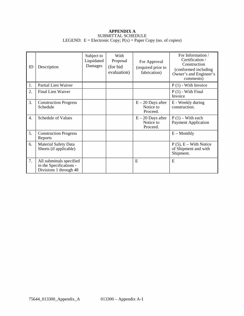
75644_013300_Appendix_A 013300 – Appendix A-1
APPENDIX A SUBMITTAL SCHEDULE
LEGEND: E = Electronic Copy; P(x) = Paper Copy (no. of copies)
ID Description
Subject to Liquidated Damages
With Proposal
(for bid evaluation)
For Approval (required prior to
fabrication)
For Information / Certification / Construction
(conformed including Owner’s and Engineer’s
comments)
1. Partial Lien Waiver P (1) - With Invoice
2. Final Lien Waiver P (1) - With Final Invoice
3. Construction Progress Schedule
E – 20 Days after Notice to Proceed.
E - Weekly during construction.
4. Schedule of Values E – 20 Days after Notice to Proceed.
P (1) – With each Payment Application
5. Construction Progress Reports
E – Monthly
6. Material Safety Data Sheets (if applicable)
P (5), E – With Notice of Shipment and with Shipment.
7. All submittals specified in the Specifications - Divisions 1 through 48
E E

81799_013300_APPENDIX_B 013300-APPENDIX B
APPENDIX B
SUBMITTAL INFORMATION BLOCK
Contractor fill in all blankswithout preprinted information
Contractor fill in this blockon all Submittals
For the use of Engineer
Contractor
(Do not send drawing to Engineerwithout Contractor’s prior Approval.)
Engineer’s ActionEn
gine
er R
ecor
d St
amp
Initials & DateDate Received
Project NameProject NumberContract TitleContract No.Spec. Sect. No. Art. No.
Approved ByDate
Contractor’s Approval(See Contract Documents)
ABCD
EFG
(See Contract Documents)
1. Use this decal on all shop drawings, whether prepared by Contractor, Subcontractor, or Supplier. Place as near as possible to the drawing title in the lower right corner.
2. Affix the gummed edge paper information blocks to all “product data” type Submittals immediately inside the front cover.
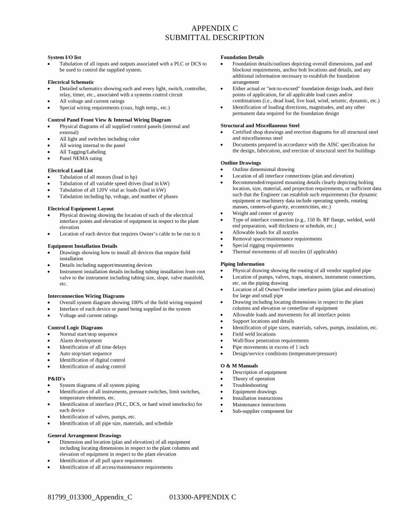
81799_013300_Appendix_C 013300-APPENDIX C
APPENDIX C SUBMITTAL DESCRIPTION
System I/O list • Tabulation of all inputs and outputs associated with a PLC or DCS to
be used to control the supplied system. Electrical Schematic • Detailed schematics showing each and every light, switch, controller,
relay, timer, etc., associated with a systems control circuit • All voltage and current ratings • Special wiring requirements (coax, high temp., etc.) Control Panel Front View & Internal Wiring Diagram • Physical diagrams of all supplied control panels (internal and
external) • All light and switches including color • All wiring internal to the panel • All Tagging/Labeling • Panel NEMA rating Electrical Load List • Tabulation of all motors (load in hp) • Tabulation of all variable speed drives (load in kW) • Tabulation of all 120V vital ac loads (load in kW) • Tabulation including hp, voltage, and number of phases Electrical Equipment Layout • Physical drawing showing the location of each of the electrical
interface points and elevation of equipment in respect to the plant elevation
• Location of each device that requires Owner’s cable to be run to it Equipment Installation Details • Drawings showing how to install all devices that require field
installation • Details including support/mounting devices • Instrument installation details including tubing installation from root
valve to the instrument including tubing size, slope, valve manifold, etc.
Interconnection Wiring Diagrams • Overall system diagram showing 100% of the field wiring required • Interface of each device or panel being supplied in the system • Voltage and current ratings Control Logic Diagrams • Normal start/stop sequence • Alarm development • Identification of all time delays • Auto stop/start sequence • Identification of digital control • Identification of analog control P&ID's • System diagrams of all system piping • Identification of all instruments, pressure switches, limit switches,
temperature elements, etc. • Identification of interface (PLC, DCS, or hard wired interlocks) for
each device • Identification of valves, pumps, etc. • Identification of all pipe size, materials, and schedule General Arrangement Drawings • Dimension and location (plan and elevation) of all equipment
including locating dimensions in respect to the plant columns and elevation of equipment in respect to the plant elevation
• Identification of all pull space requirements • Identification of all access/maintenance requirements
Foundation Details • Foundation details/outlines depicting overall dimensions, pad and
blockout requirements, anchor bolt locations and details, and any additional information necessary to establish the foundation arrangement
• Either actual or "not-to-exceed" foundation design loads, and their points of application, for all applicable load cases and/or combinations (i.e., dead load, live load, wind, seismic, dynamic, etc.)
• Identification of loading directions, magnitudes, and any other permanent data required for the foundation design
Structural and Miscellaneous Steel • Certified shop drawings and erection diagrams for all structural steel
and miscellaneous steel • Documents prepared in accordance with the AISC specification for
the design, fabrication, and erection of structural steel for buildings Outline Drawings • Outline dimensional drawing • Location of all interface connections (plan and elevation) • Recommended/required mounting details clearly depicting bolting
location, size, material, and projection requirements, or sufficient data such that the Engineer can establish such requirements (for dynamic equipment or machinery data include operating speeds, rotating masses, centers-of-gravity, eccentricities, etc.)
• Weight and center of gravity • Type of interface connection (e.g., 150 lb. RF flange, welded, weld
end preparation, wall thickness or schedule, etc.) • Allowable loads for all nozzles • Removal space/maintenance requirements • Special rigging requirements • Thermal movements of all nozzles (if applicable) Piping Information • Physical drawing showing the routing of all vendor supplied pipe • Location of pumps, valves, traps, strainers, instrument connections,
etc. on the piping drawing • Location of all Owner/Vendor interface points (plan and elevation)
for large and small pipe • Drawing including locating dimensions in respect to the plant
columns and elevation or centerline of equipment • Allowable loads and movements for all interface points • Support locations and details • Identification of pipe sizes, materials, valves, pumps, insulation, etc. • Field weld locations • Wall/floor penetration requirements • Pipe movements in excess of 1 inch • Design/service conditions (temperature/pressure) O & M Manuals • Description of equipment • Theory of operation • Troubleshooting • Equipment drawings • Installation instructions • Maintenance instructions • Sub-supplier component list

81799_013300_Appendix_D 013300-APPENDIX D
APPENDIX D
TYPICAL INSTRUCTION BOOK COVER
NAME OF
EQUIPMENT
Owner’s Name
Owner’s Facility Name
CONTRACT NUMBER 5XXX
VOLUME NUMBER*
Owner’s Name
Owner’s Facility or Plant Name
INSTRUCTION BOOK FOR
NAME OF EQUIPMENT VOLUME NUMBER*
CONTRACT NUMBER XXXX
CONTRACTOR'S NAME CONTRACTOR'S ADDRESS
CONTRACTOR’S ORDER NUMBER
Equipment Tag Number(s)
36
24
36 36 36 36
24
24 24 24
24
(Spine) (Cover) NOTES: 1. All lettering shall be a block style font such as Arial. 2. All spine lettering shall be 14 point. 3. Cover lettering shall be point sizes indicated in column to right of cover illustration. 4. *Volume number required only if instructions are contained in more than one volume

Appendix E Vendor Submittal Reference Document
9400 Ward Parkway • Kansas City, MO 64114-3319 Tel: 816 333-9400 • Fax: 816 333-3690 • www.burnsmcd.com
013301-Appendix E-1 REV: B
Overview: The following procedure is for vendors, suppliers, or contractors who will be issuing submittals to Burns & McDonnell (BMcD). If you have questions about uploading submittals, please email or call your BMcD contact. It is a step by step guide on:
• Login options o Logging in o Resetting the Password o Forgotten Passwords
• Preparing and Delivering a Submittal o Creating a Submittal o Notification of Receipt
• Picking up a Reviewed or Rejected Submittal o Notification of Completed/Rejected Documents o Download of Completed/Rejected Documents

Appendix E Vendor Submittal Reference Document
9400 Ward Parkway • Kansas City, MO 64114-3319 Tel: 816 333-9400 • Fax: 816 333-3690 • www.burnsmcd.com
013301-Appendix E-2 REV: B
Logging In: Log into BMcD WebTools at http://webtools.burnsmcd.com using the username and password sent to you by Burns and McDonnell’s IT support group.
Note: Accounts are user specific. Do not share the username and password. Others who wish to access the system should request a separate account.
Previously you were not able to change the password you received, but now it can be reset after using the initial password from BMcD. After changing the password it cannot be changed again for 24 hours. Previously used passwords cannot be used again. The Domain is BMCDEXT and should preface your username. To Login: The Domain is BMCDEXT\and should be typed in before the user name. Example: BMcDext\[user ID] so the information would be BMcDEXT\ext_jdoe.
a. You may change your password by checking the box for I want to change my password after logging on.
b. If you forgot your password you can have a new password sent to you by clicking the “Forgot your password?”

Appendix E Vendor Submittal Reference Document
9400 Ward Parkway • Kansas City, MO 64114-3319 Tel: 816 333-9400 • Fax: 816 333-3690 • www.burnsmcd.com
013301-Appendix E-3 REV: B
Login Screen:

Appendix E Vendor Submittal Reference Document
9400 Ward Parkway • Kansas City, MO 64114-3319 Tel: 816 333-9400 • Fax: 816 333-3690 • www.burnsmcd.com
013301-Appendix E-4 REV: B
Set New Password screen:
• The new password must meet BMcD password requirements: • The password has to be at least eight characters long. • The password must contain characters from at least three of the following
categories: • English uppercase characters (A - Z) • English lowercase characters (a - z) • Base 10 digits (0 - 9) • Non-alphanumeric (For example: !, $, #, or %) • The password cannot contain three or more characters from the user's
account name.

Appendix E Vendor Submittal Reference Document
9400 Ward Parkway • Kansas City, MO 64114-3319 Tel: 816 333-9400 • Fax: 816 333-3690 • www.burnsmcd.com
013301-Appendix E-5 REV: B
If you forgot your password you can have a new password sent to you by clicking the “Forgot your password”. If so, the following screen will appear for requesting a new password. Request New Password screen:
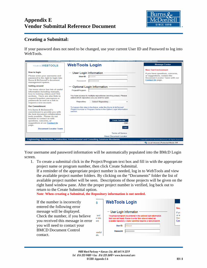
Appendix E Vendor Submittal Reference Document
9400 Ward Parkway • Kansas City, MO 64114-3319 Tel: 816 333-9400 • Fax: 816 333-3690 • www.burnsmcd.com
013301-Appendix E-6 REV: B
Creating a Submittal: If your password does not need to be changed, use your current User ID and Password to log into WebTools.
Your username and password information will be automatically populated into the BMcD Login screen.
1. To create a submittal click in the Project/Program text box and fill in with the appropriate project name or program number, then click Create Submittal. If a reminder of the appropriate project number is needed, log in to WebTools and view the available project number folders. By clicking on the “Documents” folder the list of available project number will be seen. Descriptions of those projects will be given on the right hand window pane. After the proper project number is verified, log back out to return to the Create Submittal option. Note: When creating a Submittal, the Repository information is not needed. If the number is incorrectly entered the following error message will be displayed. Check the number, if you believe you received this message in error you will need to contact your BMCD Document Control contact.

Appendix E Vendor Submittal Reference Document
9400 Ward Parkway • Kansas City, MO 64114-3319 Tel: 816 333-9400 • Fax: 816 333-3690 • www.burnsmcd.com
013301-Appendix E-7 REV: B
If this is the first time you are visiting the Submittal screen then you will be prompted to load the ActiveX Add-On that will allow you to drag and drop documents into the screen. Click on Install to load the ActiveX Add-On. Note: Some companies prohibit the install of an ActiveX Add-On. If this is the case for your system administrators please contact your BMcD representative.
After installing the Active X component, the window is now ready for files to be drag and dropped directly into the grid part of the window.

Appendix E Vendor Submittal Reference Document
9400 Ward Parkway • Kansas City, MO 64114-3319 Tel: 816 333-9400 • Fax: 816 333-3690 • www.burnsmcd.com
013301-Appendix E-8 REV: B
2. Select the files from your system and drag them into the window.
One of two options may be used in the Create Submittal window: • Drag and drop a File • Use the Add Folder or Add Files buttons in the Document Submittal window.
A vendor transmittal number will be assigned to the Submittal upon receipt. If preferred, a transmittal may be created and added to the list of files as a separate document. Please check with your project team for specific submittal needs. The Filename, client name, and project number will be pre-populated in the Create
Submittal window. Before dragging the files into the window make sure they follow the file naming requirements.
Filename should be the same as the Drawing Name or Document Number. Do not include the following in the filenames:
a. Revision b. Dates c. Transmittal Information
Note: If the document is being resubmitted then the filename must match EXACTLY with the previous submittal name.
Valid filename examples: A07-9877-8-1.pdf, M-114-1-par.pdf, A-347-wps.pdf, 18555-18 ASME calcs.pdf, Terminal Point List.pdf

Appendix E Vendor Submittal Reference Document
9400 Ward Parkway • Kansas City, MO 64114-3319 Tel: 816 333-9400 • Fax: 816 333-3690 • www.burnsmcd.com
013301-Appendix E-9 REV: B
Description is required and should relate to the document title from the title block of the
drawing. Valid description include: General Arrangements, Weld Procedures, Code Calcs, Terminal Point List, Wiring Diagram – Analyzer.
Revision should be the actual revision from the document title block. If the document does not have a revision enter a dash/hyphen (-).
Items with an * in the column name are required. Items that do not include the * may still be required by your project. Please fill in as much detail as possible unless directed otherwise by your BMCD Document Control contact. Note: Columns in the window may be resized as needed. If a drop down list is supplied then only those values may be selected. To narrow a list of items or if a value is known, it may be typed or the copy/paste option may be used into the drop down.

Appendix E Vendor Submittal Reference Document
9400 Ward Parkway • Kansas City, MO 64114-3319 Tel: 816 333-9400 • Fax: 816 333-3690 • www.burnsmcd.com
013301-Appendix E-10 REV: B
3. Click on the Upload Submittal and the files will begin to load.
4. When complete you will be prompted that the Package was successfully received. Click OK
and you will be returned to the Login Window.
Notification of Receipt:
Within a few minutes you will receive an email notice that will include a link to a transmittal receipt. If there is a correction made to the submittal you may receive an additional notice that will include a link to the updated transmittal receipt.

Appendix E Vendor Submittal Reference Document
9400 Ward Parkway • Kansas City, MO 64114-3319 Tel: 816 333-9400 • Fax: 816 333-3690 • www.burnsmcd.com
013301-Appendix E-11 REV: B
Picking up a Reviewed Submittal If your Submittal is being return after a review or is rejected, you will receive an email from the system with a link to a zip file consisting of the files. 1. To pick up the files, Click the File link.
2. After logging into WebTools you will be directed to the document for pickup. Click
on Download to get a copy of the file.
3. Select a location on your hard drive to save the file and click ok.

SECTION 014005 – CONTRACTOR QA/QC
8179975644_014005 014005-1 Copyright © 2014 Burns & McDonnell Engineering Company, Inc
PART 1 - GENERAL
1.1 GENERAL REQUIREMENTS
1.1.1 The Contractor is directly responsible for the quality of their products and services, including
those of their Subcontractors, suppliers & vendors. Acceptable quality is defined as meeting
the requirements specified in the Contract Documents.
1.1.2 The Contractor shall implement a written Quality Control System that includes the following,
as applicable, plus any supplemental procedures and/or instructions needed to meet the
requirements of the Contract Documents.
• Organizational description including corporate and project level organizational charts
showing lines of authority and reporting.
• Description of how the requirements specified in the Contract Documents are
implemented through procedures, training, drawings, forms, etc.
• Procedures for scheduling, reviewing, approving, and controlling documentation,
including records and submittals.
• Procedures for procuring materials and equipment.
• Procedures for material receipt, protection, control, security, and maintenance.
• Procedures for scheduling and performance of construction activities.
• Detailed procedures for control, verification, and acceptance of construction activities.
• Detailed procedures for identifying and controlling discrepancies from the project
requirements.
• Procedures for system acceptance, including punch-listing and sign-off.
• Procedures for scheduling and format of project turnover documentation.
1.1.3 The Contractor must submit their written Quality Control System to the Owner for review,
prior to starting work.
1.1.4 The Contractor’s personnel must have sufficient experience, training, and knowledge with the
product and processes for which they are responsible. Personnel must be familiar with the
applicable codes of construction, project specifications / requirements, and inspection and
testing operations used for verification.

SECTION 014005 – CONTRACTOR QA/QC
8179975644_014005 014005-2 Copyright © 2014 Burns & McDonnell Engineering Company, Inc
1.1.5 The Contractor is responsible for the coordination and scheduling of required tests and
inspections, and providing the Owner with sufficient prior notice to witness the required
activities.
1.1.6 The Contractor is responsible for the receipt, protection, control, security, and maintenance of
all Contractor furnished materials, including those of their Subcontractors, suppliers &
vendors, and Owner furnished materials, as specified in the Contract Documents.
1.1.7 The Contractor shall prepare a report on a monthly basis, as a minimum, of quality control
activities performed during the reporting period and submit to Owner with copies of the
quality records generated during the period.
1.1.8 The Owner may audit or inspect the Contractor’s products, services, and records to verify they
are in accordance with the written quality control system and the Contract Documents.
1.2 QUALITY CONTROL
1.2.1 The Contractor shall perform the necessary activities to verify the requirements specified in
the Contract Documents are completed correctly and in their entirety.
1.2.2 The Contractor shall document the completion of all quality control activities.
1.2.3 Minimum quality control activities associated with typical scope of work items and
specifications are defined in the Quality Control Checklists in Attachment A. The Contractor
is required to perform the specified quality control activities and complete the associated
Quality Control Checklist, as applicable for their scope of work.
1.2.4 If an appropriate Quality Control Checklists is not included in Attachment A then the
Contractor shall develop an appropriate checklist.
1.2.5 The Contractor shall utilize report forms, in conjunction with the Quality Control Checklists,
to document the results and/or status of required tests and inspections. Standard report forms
are specified in Appendix B. The Contractor may substitute their form provided that it is
equivalent and has been approved by the Owner.
1.2.6 The Contractor shall include the fully executed Quality Control Checklists and report forms
with their project turnover documentation.
1.3 PREPARATORY MEETINGS

SECTION 014005 – CONTRACTOR QA/QC
8179975644_014005 014005-3 Copyright © 2014 Burns & McDonnell Engineering Company, Inc
1.3.1 The Owner may require the Contractor QC personnel to attend a preparatory meeting prior to
starting any major work activity. The purpose of this meeting is to review the requirements
and scope of work to obtain full agreement and understanding prior to starting work.
1.4 NONCONFORMANCE CONTROL
1.4.1 The Contractor is responsible for identifying and documenting all items of nonconformance
associated with their products or services, or that of any supplier or Subcontractor to the
Contractor.
1.4.2 Items of nonconformance include the following:
• Determination that completed work or services is not in compliance with specification
requirements. This does not generally include in-process inspections and tests, such as
NDE, hydrostatic testing, etc., that are performed as part of the work.
• After the fact determination that a specified inspection, test, or other quality control
activity was not performed or at the appropriate time or was performed incorrectly.
• Loss of quality records, or control of records.
• Identification of completed work that is not in accordance with the specification
requirements specified in the Contract Documents.
• Multiple or chronic errors of the same type that have been identified during planned
quality control activities but continue to occur. This represents a failure in the quality
control system, or implementation thereof, to carry out corrective action in a timely
manner.
• Any item that may adversely impact safety or operability unless repaired by a controlled
process that has not been previously approved.
1.4.3 The Contractor is to prepare the Nonconformance Report using form CF-002, or equivalent.
This report includes several items of information that generally occur over a period of time. The
report form is therefore divided into the following sections that need to be completed as
information is generated.
Introduction
This section includes identifying information associated with the organization responsible for the
nonconformance.
Section 1 – Identification of Nonconformance

SECTION 014005 – CONTRACTOR QA/QC
8179975644_014005 014005-4 Copyright © 2014 Burns & McDonnell Engineering Company, Inc
This section includes a description of the nonconformance and the associated requirement (i.e.
how it should have been done). It will also include the name and signature of the responsible
person from the organization reporting the nonconformance, and the date reported.
Section 2 – Disposition of Nonconformance
This section provides a means to specify the proposed disposition of the nonconformance along
with a description of the necessary corrective action, if required. Disposition may be made as
one of the following three options:
• Accept As Is
• Accept pending completion and approval of corrective action.
• Reject / Scrap
The proposed disposition and associated corrective action will generally be suggested by the
Contractor. An authorized representative from Owner must approve the use of a disposition of
“Accept As Is” or “Accept pending corrective … action”. Approval must be granted in writing
and prior to either accepting the nonconformance out right or accepting it with the proposed
corrective action.
Section 3 – Acceptance of Corrective Action
This section is used to record verification that corrective action, if required, was completed and
accepted.
1.4.4 The Contractor is to provide a copy of the Nonconformance Report to the authorized OWNER
representative upon completing Section 1 and additional copies after completing each of the
remaining Sections.
1.4.5 The Contractor is to maintain a running log of all Nonconformance Reports generated on the
project, including tracking the current status for each one. The log is to be kept up-to-date
throughout the duration of the project. Use form CF-003, Nonconformance Report Log, or
equivalent.
1.4.6 The Contractor shall include the fully executed Nonconformance Report Log and all
Nonconformance Reports with their project turnover documentation.
1.5 WELDING CONTROL
1.5.1 The Contractor is responsible for controlling welding processes in accordance with the
Contract Documents.

SECTION 014005 – CONTRACTOR QA/QC
8179975644_014005 014005-5 Copyright © 2014 Burns & McDonnell Engineering Company, Inc
1.5.2 The Contractor is to maintaining a list of all welding personnel and their current qualifications
and certifications with expiration dates.
1.5.3 When specified in the Contract Documents or the applicable Quality Control Checklists, the
Contractor shall maintain a log of all welds made on the project including the location of the
weld, welder identification, welding procedure, description of required testing, and testing
results.
1.6 TESTING CONTROL
1.6.1 The Contractor is responsible for controlling testing processes in accordance with the contract
requirements.
1.6.2 The Contractor is responsible for maintaining a list of all testing personnel with their current
qualifications and certifications including expiration dates.
1.6.3 The Contractor shall prepare a list of all required tests and record when the test was performed
and the results. This list shall be updated on a regular basis.
1.7 MATERIAL CONTROL
1.7.1 The term material, as used herein, includes materials, equipment, parts, components,
assemblies, etc.
1.7.2 The Contractor shall establish a system to document and control material receipt, status
(accepted or rejected), jobsite transportation routes, storage location, maintenance
requirements and activities, removal from storage, and material setting. The system will
comply, as a minimum, with the requirements of this procedure and the Contract Documents.
The Contractor shall submit the system to Owner for approval prior to receiving and storing
material at the jobsite.
1.7.3 The Contractor shall receive and unload materials in accordance with the contract
requirements and the requirements of this procedure (see Appendix C for specific types of
materials and equipment).
1.7.4 The Contractor shall notify Owner prior to unloading any materials that are hazardous,
radioactive, or may otherwise be unsafe.
1.7.5 Prior to releasing carriers of materials delivered to jobsites, the Contractor shall verify
quantities received match the shipping papers and perform a general inspection of the
materials and shipping containers to verify they are labeled or tagged appropriately and that no

SECTION 014005 – CONTRACTOR QA/QC
8179975644_014005 014005-6 Copyright © 2014 Burns & McDonnell Engineering Company, Inc
damage occurred during shipment. If acceptable, Contractor shall sign the shipping papers,
retain one copy, and release the carrier. If unacceptable, the Contractor shall hold the carrier
and immediately notify the Owner.
1.7.6 The Contractor shall complete a Material Receiving Report, form CF-004 or equivalent, for
each material receipt. Contractor shall sign and date each report, attach the signed Bill of
Lading, and promptly submit to Owner.
1.7.7 The Contractor shall document discrepancies with regard to the quantities and/or condition of
the material receipt by completing a supplemental Overage, Shortage, and Damage Report,
form CF-007 or equivalent. Contractor shall sign and date each report, obtain carrier’s
signature, and promptly submit a copy to the carrier and Owner with the associated Material
Receiving Report.
1.7.8 The Contractor shall maintain a Material Receiving Log, Form CF-005 or equivalent, as a
consolidated record of all items received and the associated Material Receiving Report
number.
1.7.9 The Contractor shall file any documentation received with the shipment such as storage
requirements, installation instructions, drawings, and operating manuals. Documentation shall
be turned over to Owner before the Contractor’s request for acceptance or as requested.
1.7.10 The Contractor shall store materials that are not immediately installed in accordance with the
general requirements of this procedure and the requirements in Appendix C for specific types
of materials and equipment.
1.7.11 The Contractor is responsible for the protection and security of materials in storage.
1.7.12 The Contractor shall maintain identification of all materials throughout storage.
1.7.13 The Contractor shall prepare laydown areas, and provide storage facilities when specified in
the Contract Documents.
1.7.14 The storage area must be situated in a location that provides adequate drainage of water runoff
or is otherwise prepared to account for surface water for storing and retrieving material.
1.7.15 Laydown areas must placed in areas that are free from overhead contaminates and will be
accessible during future planned construction activities.
1.7.16 Material shall be stored in a facility or area suitable to the intended use of the material.
Material designed to be used indoors shall be stored indoors. Material designed to be used in
SECTION 014005 – CONTRACTOR QA/QC
8179975644_014005 014005-7 Copyright © 2014 Burns & McDonnell Engineering Company, Inc
a climate controlled environment shall be stored in the same environment. Material designed
to be used outdoors may generally be stored outdoors except smaller items will generally be
kept indoors for security purposes.
1.7.17 The Contractor is responsible for verifying materials are properly prepared prior to being
stored outside or in non-climate controlled environments.
1.7.18 Materials shall be stored in a manner that will prevent them from shifting or falling and
damaging the material or injuring personnel.
1.7.19 Materials received in boxes, crates, etc., shall be stored on pallets or skids.
1.7.20 Material stored in laydown areas shall be placed on cribbing or timbers to keep from
contacting mud, gravel, surface water, etc.
1.7.21 Weatherproof coverings for outdoor storage shall utilize waterproof, flame resistant type
sheeting. Sheeting widths are the maximum practical and, if necessary, widths may be built
up by using waterproof taped splices. The sheeting is carefully placed and tied down to
prevent moisture from entering the laps and to prevent wind damage to the coverings. The
sheeting shall cover the top and sides of the equipment and be fastened securely around the
base of the equipment.
1.7.22 The Contractor shall keep a log of all materials entered into and removed from storage
including the time a date of entry and removal. The Contractor shall submit this log to the
Owner on a monthly basis or as requested.
1.7.23 The Contractor shall maintain and preserve equipment during storage in accordance with the
minimum requirements specified in Appendix C and additional requirements specified as
manufacturer’s recommendations. The Contractor is responsible for obtaining and reviewing
the manufacturer’s recommendations for all items. The Contractor shall notify the Owner in
the event that manufacturer’s recommendations are not available.
1.7.24 The Contractor shall maintain a record of all maintenance activities performed for each
equipment item, and submit the completed and/or updated records to the Owner on a Monthly
basis or as requested.
1.8 SYSTEM ACCEPTANCE
1.8.1 The Contractor will complete the following activities prior to presenting systems to the Owner
for acceptance (unless a prior arrangement was made for joint final inspections):

SECTION 014005 – CONTRACTOR QA/QC
8179975644_014005 014005-8 Copyright © 2014 Burns & McDonnell Engineering Company, Inc
• Fully execute and document all required activities within the Contractor’s scope of
work. This will include completing the system applicable Quality Control Checklists,
testing and examination reports, and logs.
• Make a final inspection of all work performed on the system, complete the associated
documentation, and develop a punch list of any and all items that are incomplete or
are not in accordance with project requirements at that time.
1.9 PROJECT TURNOVER DOCUMENTATION
1.9.1 The Contractor shall maintain and file all quality records at the jobsite including Quality
Control Checklists, test reports and records, nonconformance reports, weld logs, material
certifications, etc.
1.9.2 The Contractor shall label and assemble all quality records into turnover packages by unit or
area as specified in the Contract Documents.
1.9.3 The Contractor shall provide the complete turnover packages to the Owner prior to or at the
time of completing their work.

QUALITY CONTROL REQUIREMENTS FOR CONTRACTORS
Appendix A – Quality Control Checklists
8179975644_014005 014005-9 Copyright © 2014 Burns & McDonnell Engineering Company, Inc
Procedure No. Quality Verification Checklists Rev SECTION - 1 SITE WORK
QVC-1.01 Checklist for Surveying 0
QVC-1.02 Checklist for Demolition 0
QVC-1.03 Checklist for Excavation and Backfill 0
QVC-1.05 Checklist for Plant Road and Vehicle Parking 0
QVC-1.08 Checklist for Piling 0
QVC-1.09 Checklist for Drilled Piers 1
SECTION - 2 CONCRETE
QVC-2.01 Checklist for Concreting 1
SECTION - 3 STRUCTURAL STEEL
QVC-3.01 Checklist for Structural Steel Erection 0
SECTION - 4 BUILDINGS
QVC-4.01 Checklist for Buildings 0
SECTION - 5 PIPING
QVC-5.01 Checklist for Underground Piping 0
SECTION - 7 EQUIPMENT SETTING
QVC-7.01 Checklist for Stationary Equipment 0
QVC-7.02 Checklist for Rotating Equipment 0
SECTION - 8 COATINGS
QVC-8.01 Checklist for Coatings Application 0
SECTION - 9 INSULATION, FIREPROOFING AND HEAT TRACE

QUALITY CONTROL REQUIREMENTS FOR CONTRACTORS
Appendix B – Quality Control Forms
8179975644_014005 014005-10 Copyright © 2014 Burns & McDonnell Engineering Company, Inc
Form No. Construction Forms Rev SECTION - 0 GENERAL
CF-001 Notice of Acceptance 2
CF-002 Nonconformance Report 0
CF-003 Non-Conformance Report Log 0
CF-004 Material Receiving Report 0
CF-005 Material Receiving Log 0
CF-006 Signoff Contractor to Burns & McDonnell 3
CF-007 Receiving Overage, Shortage, and Damage Report 0
CF-008 Welding Conformance 0
CF-009 Master Punch list 0
CF-010 Equipment Maintenance Log 0
CF-011 Daily Field Report 2
CF-012 Drawing Control Audit 1
CF-013 Quality Performance Measurement System 2
CF-014 Inspection Matrix 0
SECTION - 1 SITE WORK
CF-101 Pier/Pile Installation Log 0
CF-102 Soils Log 0
CF-103 Authorization to Backfill Record 1
SECTION - 2 CONCRETE
CF-200 Concrete Placement Log 0
CF-201 Concrete Placement Application, Authorization, and Record 1
CF-202 Grout Placement Application, Authorization, and Record 2
SECTION - 3 STRUCTURAL STEEL
CF-301 Structural Steel Authorization and Acceptance Record 4
SECTION - 4 BUILDINGS
Use QVC-4.01 Checklist for Buildings
SECTION - 5 PIPING
CF-501 Piping Pressure Test Record 2
CF-502 System Line Tracker 0
CF-503 Holiday Test Record Log 3
CF-504 Tie-In Application, Authorization, and Record 1
SECTION - 6 ELECTRICAL
Electrical Forms current QV6.02-1a thru QV6.02-18
SECTION - 7 EQUIPMENT SETTING
CF-701 Equipment Installation Log 0
CF-702 Stationary Equipment Placement Application, Authorization, and Record 1
CF-703 Equipment Plumb Record 1
CF-704 Final Closing Authorization Record 2
CF-705 Rotating Equipment Placement Application, Authorization, and Record 1
CF-706 Coupling Alignment Record 1
SECTION - 8 COATINGS

QUALITY CONTROL REQUIREMENTS FOR CONTRACTORS
Appendix B – Quality Control Forms
8179975644_014005 014005-11 Copyright © 2014 Burns & McDonnell Engineering Company, Inc
CF-801 Coating Record 1
SECTION - 9 INSULATION, FIREPROOFING AND HEAT TRACE
CF-901 Insulation Placement Application, Authorization, and Record 1
CF-902 Fireproofing Placement Application, Authorization, and Record 1
CF-904 Electric Tracing Placement Application, Authorization, and Record 1
SECTION - 10 SPECIAL PROCESSES
CF-1001 Weld Log / Traveler 0
CF-1002 Welder Qualification and Maintenance Log 0
CF-1003 Hot Tap Form 1
CF-1004 NDE Rejects 0

QUALITY CONTROL REQUIREMENTS FOR CONTRACTORS
Appendix C – Receiving, Storage, and Maintenance Requirements for Specific Types of Materials and Equipment
Item Receiving and Storage Maintenance
8179975644_014005 014005-12 Copyright © 2014 Burns & McDonnell Engineering Company, Inc
All Items • Verify alloy materials were not shipped in contact with carbon steel.
• Do not store alloy materials in contact with carbon steel.
• Inspect coatings for shipping damage prior to unloading, when possible.
• Inspect flange faces or verify covers were in place to prevent damage during shipment.
• Verify nozzles beveled for field welds are protected.
• Verify individual items are marked or tagged as required.
• Verify items potentially subject to freezing temperatures are drained and sealed prior to storage.
• Verify on a continual basis that materials are stored in a manner that prevents contact with debris, ground water, etc.
• Verify on a continual basis that protective covers remain in place until installation.
• Verify on a continual basis that ferrous machined surfaces remain coated with rust preventative.
• Maintain internal purge with inert gas, when required.
• Continually check seals on items stored outside.
• Remove storage oils and lubricants and replace with the correct grade.
Pipe • Store on timbers or cribbing. • Store with pipe caps or closed ends.
Valves • Store all control and relief valves and other smaller general valves (< 4”) indoors.
• Store manually operated plug and ball valves in the open position and other types in the closed position.
• Store with actuators or wheel operators in the upright position.
Instruments • Store indoors in a climate controlled environment with desiccant in original sealed shipping containers.
Static Equipment (Pressure Vessels, Heat Exchangers, etc.)
• Verify interior is clean and dry. • Verify threaded openings are capped or
plugged. • Store large items outdoors off ground on
timbers.
Rotating Equipment • Inspect bearings for damage during transit. • Verify oil reservoirs are properly filled. • Verify equipment is prepared for long term
storage, when required. • For pumps with mechanical seals, fill
stuffing box with lubricating oil. • For pumps with service packing installed,
remove packing and repack with packing dipped in oil
• Check oil reservoir levels and rotate shafts at least 1 ¼ turns on a weekly basis or as recommended by the manufacturer.
• Verify Babbitt bearings are completely submerged in lubricant prior to rotating, when applicable.
• Use vapor phase inhibitor to minimize condensation. Identify openings used to introduce inhibitor for later removal prior to start-up.
• Spray internal packing with lubricating oil every two weeks.

QUALITY CONTROL REQUIREMENTS FOR CONTRACTORS
Appendix C – Receiving, Storage, and Maintenance Requirements for Specific Types of Materials and Equipment
Item Receiving and Storage Maintenance
8179975644_014005 014005-13 Copyright © 2014 Burns & McDonnell Engineering Company, Inc
Reciprocating Equipment
• Coat exposed rods, eccentrics, plungers, and machined surfaces with rust preventative.
• Ensure non-lubricated type compressors with Teflon or carbon pistons or piston rings are kept sealed, purged, and pressurized. Do not add oil to non-lubricated type compressors.
• Turn crankcase 2 ½ turns and operate lubricators twice weekly.
• Operate manual priming pump, when installed, at least one minute twice weekly.
Motors • Loosen drain plugs in explosion proof and TEFC motors to allow accumulated moisture to drain.
• Remove brushes and store in a climate controlled area where condensation will not occur.
• Close conduit connections and protect with plastic plugs.
• Coat collector rings on A-C units with petroleum jelly.
• Measure and record insulation resistance values for each winding on motors equal to or greater than 600V. Record temperature and weather conditions at time of measurement.
• Six weeks before start-up, measure and record insulation resistance values for each winding on motors equal to or greater than 600V. Record temperature and weather conditions at time of measurement.
• For grease lubricated motors, inspect bearing grease at least every six months. If deteriorated, clean and repack bearings in accordance with manufacturer’s instructions.
Transformers • Store indoors in dust free area (except for units designed for outdoor operation).
• Cover bushings.
• For liquid filled units, monitor liquid level on a weekly basis.
• For gas blanketed units, monitor gas pressure on a weekly basis.
Electrical Equipment (Switchgear, Starters, Control Equipment, etc.)
• Store indoors unless units are furnished with weatherproof enclosures.
• Oil immersed equipment that is shipped dry shall be stored indoors.
• Provide aux. heaters, if necessary, and energize.
• Allow for adequate ventilation in order to prevent mildew and corrosion.
• Store free standing enclosed control equipment in the upright position.
• Check aux. heaters on a daily basis.
END OF SECTION 014005

81799_014200 014200-1
SECTION 014200 - DEFINITIONS AND STANDARDS
PART 1 - GENERAL
1.01 SUMMARY: A. Definitions:
1. Basic contract definitions used in the Contract Documents are defined in Attachment A – Commercial Terms and Conditions of the Contract. Definitions and explanations are not necessarily either complete or exclusive, but are general for the Work.
2. General Requirements are the provisions or requirements of DIVISION 1 Sections, and which apply to the entire Work of the Contract.
B. Related Information Specified Elsewhere: Specification standards and associations applicable to the Work are specified in each Section.
1.02 SPECIFICATION FORMAT AND CONTENT EXPLANATIONS: A. Specification Format: The Specifications are organized into Divisions and Sections based on
the Construction Specifications Institute's (CSI) Section Format and MasterFormat numbering system. Some portions may not fully comply and no particular significance will be attached to such compliance or noncompliance. 1. Divisions and Sections: For convenience, a basic unit of Specification text is a "Section,"
each unit of which is numbered and named. These are organized with related Sections, into "Divisions," which are recognized as the present industry consensus on uniform organization and sequencing of Specifications. The Section title is not intended to limit meaning or content of Section, nor to be fully descriptive of requirements specified therein, nor to be an integral part of text.
2. Section Numbering: Used for identification and to facilitate cross-references in Contract Documents. Sections are placed in numeric sequence; however, numbering sequence is not complete, and listing of Sections in Table of Contents at beginning of the Project Manual must be consulted to determine numbers and names of Specification Sections in these Contract Documents.
3. Page Numbering: Numbered independently for each Section. Section number is shown with page number at bottom of each page, to facilitate location of text.
4. Parts: Each Section of Specifications generally has been subdivided into three basic "parts" for uniformity and convenience (PART 1 - GENERAL, PART 2 - PRODUCTS, and PART 3 - EXECUTION). These "Parts" do not limit the meaning of text within. Some Sections may not contain all three "Parts" when some are not applicable, or may contain more than three "Parts" to add clarity to organization of Section.
5. Underscoring of Titles: Used strictly to assist reader of Specification in scanning text for key words in content. No emphasis on or relative importance is intended except where underscoring may be used in body of text to emphasize a duty, critical requirement, or similar situation.
6. Project Identification: Project file number and identification are recorded at bottom of each page of Specifications to minimize possible misuse of Specifications, or confusion with other Project Specifications.
B. Specification Content: 1. These Specifications apply certain conventions in the use of language and the intended
meaning of certain terms, words, and phrases when used in particular situations or circumstances. These conventions are explained as follows: a. Imperative and Streamlined Language: These Specifications are written in
imperative and abbreviated form. This imperative language of the technical

SECTION 014200 - DEFINITIONS AND STANDARDS: continued
014200-2 81799_014200
Sections is directed at the Contractor, unless specifically noted otherwise. Incomplete sentences shall be completed by inserting "shall," "the Contractor shall," and "shall be," and similar mandatory phrases by inference in the same manner as they are applied to notes on the Drawings. The words "shall be" shall be supplied by inference where a colon (:) is used within sentences or phrases. Except as worded to the contrary, fulfill (perform) all indicated requirements whether stated imperatively or otherwise.
b. Specifying Methods: The techniques or methods of specifying requirements varies throughout text, and may include "prescriptive," "compliance with standards," "performance," "proprietary," or a combination of these. The method used for specifying one unit of Work has no bearing on requirements for another unit of Work.
c. Overlapping and Conflicting Requirements: Where compliance with two or more industry standards or sets of requirements is specified, and overlapping of those different standards or requirements establishes different or conflicting minimums or levels of quality, notify Engineer in writing for a decision, which Engineer will render in writing within a reasonable time.
d. Abbreviations: Throughout the Contract Documents are abbreviations implying words and meanings which shall be appropriately interpreted. Specific abbreviations have been established, principally for lengthy technical terminology and in conjunction with coordination of Specification requirements with notations on Drawings and in schedules. These are normally defined at first instance of use. Organizational and association names and titles of general standards are also abbreviated.
C. Assignment of Specialists: In certain instances, Specification text requires that specific Work be assigned to specialists in the operations to be performed. These specialists shall be engaged for performance of those units of Work, and assignments are requirements over which Contractor has no choice or option. These assignments shall not be confused with, and are not intended to interfere with, enforcement of building codes and similar regulations governing the Work, local trade and union jurisdictions, and similar conventions. Nevertheless, final responsibility for fulfillment of Contract requirements remains with Contractor.
D. Trades: Except as otherwise specified or indicated, the use of titles such as "carpentry" in Specification text, implies neither that the Work must be performed by an accredited or unionized tradesperson of corresponding generic name (such as "carpenter"), nor that specified requirements apply exclusively to work by tradespersons of that corresponding generic name.
1.03 DRAWING SYMBOLS: A. Except as otherwise indicated, graphic symbols used on Drawings are those symbols
recognized in the construction industry for purposes indicated. Refer instances of uncertainty to Engineer for clarification.
1.04 INDUSTRY STANDARDS: A. Applicability of Standards: Except where the Contract Documents include more stringent
requirements, applicable construction industry standards have the same force and effect as if bound or copied directly into the Contract Documents. Such standards are made a part of the Contract Documents by reference and are stated in each Section. 1. Referenced standards, referenced directly in Contract Documents or by governing
regulations, have precedence over nonreferenced standards which are recognized in industry for applicability to the Work.

SECTION 014200 - DEFINITIONS AND STANDARDS: continued
81799_014200 014200-3
2. Where compliance with an industry standard is required, the latest standard in effect at time of opening Bids shall govern.
3. Where an applicable code or standard has been revised and reissued after the effective date of the Contract and before performance of Work affected by the revision, Engineer will decide whether to issue a Change Order to proceed with the revised standard.
4. In every instance the quantity or quality level shown or specified shall be the minimum to be provided or performed. The actual installation may comply exactly, within specified tolerances, with the minimum quantity or quality specified, or it may exceed that minimum within reasonable limits. In complying with these requirements, indicated numeric values are minimum or maximum values, as noted, or appropriate for the context of the requirements. Refer instances of uncertainty to Engineer for a decision before proceeding.
5. Each entity engaged in construction on the Project is required to be familiar with industry standards applicable to that entity's construction activity. Copies of applicable standards are not bound with the Contract Documents. a. Where copies of standards are needed for performance of a required construction
activity, Contractor shall obtain copies directly from the publication source. B. Abbreviations and Names: Trade association names and titles of general standards are
frequently abbreviated. Where such acronyms or abbreviations are used in the Specifications or other Contract Documents, they mean the recognized name of the trade association, standards generating organization, authority having jurisdiction, or other entity applicable to the context of the text provision.
PART 2 - PRODUCTS - Not Applicable.
PART 3 - EXECUTION - Not Applicable END OF SECTION 014200

81799_015200 015200-1
SECTION 015200 - FIELD OFFICES AND SHEDS
PART 1 - GENERAL
1.01 SUMMARY: A. This Section includes requirements for temporary field offices and other structures required for
office and storage space required by Contractor. B. Related Work Specified Elsewhere:
1. Equipment and Materials: SECTION 016000. 2. Temporary Utilities and Facilities: SECTION 015600.
C. Use of Existing Facilities: 1. Existing facilities at the Site shall not be used for field offices.
D. Use of Permanent Facilities: 1. Permanent facilities when substantially completed shall not be used for field offices or
for storage.
PART 2 - PRODUCTS
2.01 FIELD OFFICES: A. General:
1. Provide trailers, mobile buildings, or buildings constructed with floors raised aboveground, with steps, landings, and railings at entrance doors.
2. Buildings shall be structurally sound, secure, and weathertight. 3. Provide appropriate type fire extinguishers at each office and storage area. 4. Maintain offices during progress of the Work.
B. Contractor's Office: 1. Provide a field office for Contractor's superintendent on the Site, if required by
Contractor’s operations. 2. It shall be of size required for general use, with lights, heat, furnishings, telephone
service, and other necessary facilities and utilities required by Contractor's operations.
2.02 STORAGE SHEDS AND TRAILERS: A. On Site:
1. Provide temporary buildings or trailers needed for storage of Equipment and Materials installed under this Contract.
2. Provide ventilation and heating as required by Equipment and Material stored. B. Off Site:
1. Advise Engineer of any arrangements made for storage of Equipment and Materials in a place other than Owner's Site. Furnish evidence of insurance coverage with Application for Payment as specified by the Contract Documents.
PART 3 - EXECUTION
3.01 LOCATION, INSTALLATION AND MAINTENANCE: A. General:
1. Place temporary buildings, trailers, and stored Materials in locations acceptable to Engineer.
2. Install field offices and sheds to resist winds and elements of the locality where installed. 3. Remove when no longer needed at the Site or when Work is completed. 4. Keep approach walks free of leaves, mud, water, ice, or snow.

SECTION 015200 - FIELD OFFICES AND SHEDS: continued
015200-2 81799_015200
5. At completion of Work, remove temporary buildings and trailers, foundations (if any), utility services, and debris.
6. Prepare ground or paved areas as required by Contractor’s operations. END OF SECTION 015200
81799_015300 015300-1
SECTION 015300 - TEMPORARY BARRIERS AND CONTROLS
PART 1 - GENERAL
1.01 SUMMARY: A. This Section includes General Requirements for:
1. Safety and protection of Work. 2. Safety and protection of existing property. 3. Barriers. 4. Security. 5. Environmental controls. 6. Access roads and parking areas. 7. Traffic control and use of roadways. 8. Railroad service.
B. Related Work Specified Elsewhere: 1. Temporary Utilities and Facilities: SECTION 015600.
PART 2 - PRODUCTS – NOT APPLICABLE
PART 3 - EXECUTION
3.01 SAFETY AND PROTECTION OF WORK AND PROPERTY: A. General:
1. Provide for the safety and protection of the Work and of Materials and Equipment to be incorporated therein, whether in storage on or off the Site. Provide protection at all times against rain, wind, storms, frost, freezing, condensation, or heat so as to maintain all Work and Equipment and Materials free from injury or damage. At the end of each day, all new Work likely to be damaged shall be appropriately protected.
2. Notify Engineer immediately at any time operations are stopped due to conditions which make it impossible to continue operations safely or to obtain proper results.
3. Construct and maintain all necessary temporary drainage and do all pumping necessary to keep excavations, floors, pits, trenches, manholes, and ducts free of water.
4. Protect floors from damage by proper covering and care when handling heavy equipment, painting, or handling mortar or other such materials. Use proper cribbing and shoring to prevent overloading of floors while moving heavy equipment. Provide metal pans under pipe-threading machines and clean such pans daily, keeping oil off floors. Restore floors to former condition where damaged or stained.
5. Concrete floors less than 28 Days old shall not be loaded without written permission from Engineer.
6. Restrict access to roofs except as required by the Work. Where access is required, provide protection with plywood, boards, or other suitable materials.
3.02 BARRIERS: A. General:
1. Furnish, install, and maintain suitable barriers as required to prevent public entry, to protect the public, and to protect the Work, existing facilities, trees, and plants from construction operations. Remove when no longer needed or at completion of Work.
2. Materials may be new or used, suitable for the intended purpose, but shall not violate requirements of applicable codes and standards or regulatory agencies.

SECTION 015300 - TEMPORARY BARRIERS AND CONTROLS: continued
015300-2 81799_015300
3. Barriers shall be of a neat and reasonable uniform appearance, structurally adequate for the required purposes.
4. Maintain barriers in good repair and clean condition for adequate visibility. Relocate barriers as required by progress of Work.
5. Repair damage caused by installation and restore area to original or better condition. Clean the area.
3.03 ENVIRONMENTAL CONTROLS: A. Dust Control:
1. Provide positive methods and apply dust control materials to minimize raising dust from construction operations; and to prevent airborne dust from dispersing into the atmosphere.
2. Schedule operations so that dust and other contaminants resulting from cleaning process will not fall on wet or newly-coated surfaces.
B. Water and Erosion Control: 1. Provide methods to control surface water to prevent damage to the Project, the Site, or
adjoining properties. 2. Plan and execute construction and earthwork by methods to control surface drainage from
cuts and fills, and from borrow and waste disposal areas, to prevent erosion and sedimentation. a. Hold the areas of bare soil exposed at one time to a minimum. b. Provide temporary control measures such as berms, dikes, and drains.
3. Control fill, grading, and ditching to direct surface drainage away from excavations, pits, tunnels, and other construction areas; and to direct drainage to proper runoff.
4. Provide, operate, and maintain hydraulic equipment of adequate capacity to control surface and groundwater.
5. Treat and dispose of surface runoff water in a manner to prevent flooding, erosion, sedimentation, or other damage to any portion of the Site or to adjoining areas, and in a manner acceptable to authorities having jurisdiction.
6. Provide temporary drainage where the roofing or similar waterproof deck construction is completed prior to the connection and operation of the permanent drainage piping system.
C. Debris Control and Clean-Up: 1. Keep the premises free at all times from accumulations of debris, waste materials, and
rubbish caused by construction operations and employees. Responsibilities shall include: a. Adequate trash receptacles about the Site, emptied promptly when filled. b. Periodic cleanup to avoid hazards or interference with operations at the Site and to
maintain the Site in a reasonably neat condition. c. The keeping of construction materials such as forms and scaffolding neatly stacked. d. Immediate cleanup to protect the Work by removing splattered concrete, asphalt,
oil, paint, corrosive liquids, and cleaning solutions from walls, floors, and metal surfaces before surfaces are marred.
2. Prohibit overloading of trucks to prevent spillages on access and haul routes. Provide periodic inspection of traffic areas to enforce requirements.
3. Final cleanup is specified in SECTION 017800 - CONTRACT CLOSEOUT.

SECTION 015300 - TEMPORARY BARRIERS AND CONTROLS: continued
81799_015300 015300-3
D. Pollution Control: 1. Provide methods, means, and facilities required to prevent contamination of soil, water,
or atmosphere by the discharge of hazardous or toxic substances from construction operations.
2. If indicated in contract drawings, provide equipment and personnel, perform emergency measures required to contain any spillages, and remove contaminated soils or liquids. Excavate and dispose of any contaminated earth off-Site in approved locations, and replace with suitable compacted fill and topsoil.
3. Take special measures to prevent harmful substances from entering public waters, sanitary, or storm sewers.
3.04 ACCESS ROADS AND PARKING AREAS: A. Existing On-Site Roads and Parking Areas:
1. Designated existing on-Site streets and parking facilities may be used for construction traffic. a. Provide temporary additional roads as needed for required construction access. b.a. Maintain existing construction, and restore to original, better, or specified condition
at completion of Work. c.b. Do not allow heavy vehicles or construction equipment in parking areas.
2. Do not allow existing on-Site streets, parking facilities, or walks to be used for construction traffic, equipment, or personnel once new plant entrance road is completed.
3.05 TRAFFIC CONTROL AND USE OF ROADWAYS: A. Maintenance of Roadways:
1. Repair roads, walkways, and other traffic areas damaged by operations. Keep traffic areas as free as possible of constructionexcavated materials and maintain in a manner to eliminate dust, mud, and hazardous conditions.
2. All operations and repairs shall meet the approval of owners or agencies having jurisdiction.
END OF SECTION 015300

81799_015600 01560-1
SECTION 01560 - TEMPORARY UTILITIES AND FACILITIES
PART 1 - GENERAL
1.01 SUMMARY: A. This Section includes requirements of a temporary nature not normally incorporated into final
Work. It includes the following: 1. Utility services. 2. Construction and support facilities. 3. Construction aids.
B. Related Work Specified Elsewhere: 1. Temporary Barriers and Controls: SECTION 015300. 2. Field Offices and Sheds: SECTION 015200.
1.02 REFERENCES: A. American National Standards Institute (ANSI):
1. A10 Series - Safety Requirements for Construction and Demolition. B. National Electrical Contractors Association (NECA):
1. Electrical Design Library - Temporary Electrical Facilities. C. National Fire Protection Association (NFPA):
1. 10 - Portable Fire Extinguishers. 2. 70 - National Electrical Code. 3. 241 - Safeguarding Construction, Alterations, and Demolition Operations.
D. National Electrical Manufacturers Association (NEMA). E. Underwriters Laboratories (UL).
1.03 QUALITY ASSURANCE: A. Regulations: Comply with industry standards and applicable laws and regulations of
authorities having jurisdiction, including but not limited to: 1. Building Code requirements. 2. Health and safety regulations. 3. Utility company regulations. 4. Police, Fire Department, and rescue squad rules. 5. Environmental protection regulations.
B. Standards: 1. Comply with NFPA 10 and 241, and ANSI A10 Series standards "Temporary Electrical
Facilities." 2. Comply with NEMA, NECA, and UL standards and regulations for temporary electric
service. Install service in compliance with NFPA 70. C. Inspections: Arrange for authorities having jurisdiction to inspect and test each temporary
utility before use. Obtain required certifications and permits.
1.04 PROJECT CONDITIONS: A. Temporary Utilities: Prepare a schedule indicating dates for implementation and termination
of each temporary utility. At the earliest feasible time, when acceptable to Owner, change over from use of temporary service to use of the permanent service.
B. Conditions of Use: Keep temporary services and facilities clean and neat in appearance. Operate in a safe and efficient manner. Take necessary fire prevention measures. Do not overload facilities, or permit them to interfere with progress. Do not allow hazardous, dangerous, unsanitary conditions, or public nuisances to develop or persist on the Site.

SECTION 01560 - TEMPORARY UTILITIES AND FACILITIES: continued
01560-2 81799_015600
PART 2 - PRODUCTS
2.01 MATERIALS AND EQUIPMENT: A. Provide new materials and equipment. If acceptable to Engineer, undamaged previously used
materials and equipment in serviceable condition may be used. Provide materials and equipment suitable for the use intended, of capacity for required usage, and meeting applicable codes and standards. Comply with requirements of DIVISIONS 2 through 48.
B. Water: Provide potable water approved by local health authorities. C. Water Hoses: Provide 3/4-inch (19-mm), heavy-duty, abrasion-resistant, flexible rubber hoses
100 feet (30 m) long, with pressure rating greater than the maximum pressure of the water distribution system. Provide adjustable shutoff nozzles at hose discharge.
D. Electrical Outlets: Provide properly configured, NEMA-polarized outlets to prevent insertion of 110- to 120V plugs into higher voltage outlets. Provide receptacle outlets equipped with ground-fault circuit interrupters, reset button, and pilot light for connection of power tools and equipment.
E. Electrical Power Cords: Provide grounded extension cords. Use hard-service cords where exposed to abrasion and traffic. Provide waterproof connectors to connect separate lengths of electric cords if single lengths will not reach areas where construction activities are in progress. Do not exceed safe length-voltage ratio.
F. Lamps and Light Fixtures: Provide general service incandescent lamps of wattage required for adequate illumination. Provide guard cages or tempered-glass enclosures where exposed to breakage. Provide exterior fixtures where exposed to moisture.
G. Heating Units: Provide temporary heating units that have been tested and labeled by UL, FM, or another recognized trade association related to the type of fuel being consumed.
H. Fire Extinguishers: Provide hand-carried, portable, UL-rated, Class A fire extinguishers for temporary offices and similar spaces. In other locations, provide hand-carried, portable, UL-rated, Class ABC, dry-chemical extinguishers or a combination of extinguishers of NFPA-recommended classes for the exposures. Comply with NFPA 10 and NFPA 241 for classification, extinguishing agent, and size required by location and class of fire exposure.
PART 3 - EXECUTION
3.01 TEMPORARY UTILITIES: A. General:
1. Provide adequate utility capacity at each stage of construction. Prior to availability of temporary utilities at the Site, provide trucked-in services as required for start-up of construction operations.
2. Furnish, install, and maintain temporary utilities required for adequate construction, safety, and security. Modify, relocate, and extend systems as Work progresses. Repair damage caused by installation or use of temporary facilities. Remove on completion of Work or until service or facilities are no longer needed or are replaced by authorized use of completed permanent facilities.
3. The types of temporary construction utilities and facilities required include, but not by way of limitation, water distribution, drainage, dewatering equipment, enclosure of Work, heat, ventilation, electrical power distribution, lighting, hoisting facilities, stairs, ladders, and roads.
4. Inspect and test each service before placing temporary utilities in use. Arrange for required inspections and tests by governing authorities, and obtain required certifications and permits for use.

SECTION 01560 - TEMPORARY UTILITIES AND FACILITIES: continued
81799_015600 01560-3
5. Materials used for temporary service shall not be used in the permanent system unless so specified or acceptable to Engineer.
B. Because of operational requirements, Owner may restrict or curtail Contractor's use of electric power, water, compressed air, and natural gas. If these utilities are critical to Contractor's operations and completion of the Contract on the agreed schedule, Contractor shall consider furnishing alternate sources for its own use. Restriction or curtailment of these utilities shall not be a basis for a claim against Owner or an extension of the agreed schedule.
3.02 TEMPORARY ELECTRICITY AND LIGHTING: A. Use of Existing System:
1. Owner will not provide provisions for temporary electricity. B. Use of Permanent System:
1. Prior to use of permanent system for construction purposes, obtain written permission of Owner.
2. Maintain permanent system as specified for temporary facilities.
3.03 TEMPORARY WATER: A. Use of Existing System:
1. Owner will provide limited provisions for connection to the existing system for temporary water.
B. Use of Permanent System: 1. Prior to use of permanent system for construction purposes, obtain written permission of
Owner. 2. Prior to Use of System for Drinking Water:
a. Disinfect piping. b. Obtain inspection and approval of governing authority.
3.04 TEMPORARY GAS: A. Use of Existing System:
1. Owner will not provide provisions for connection to the existing system for temporary natural gas. Contractor to inform Owner Prior to starting work if natural gas is required to perform the Work.
B. Use of Permanent System: 1. Prior to use of permanent system for construction purposes, obtain written permission of
Owner. 2. Prior to use of system, obtain inspection and approval of governing authority. 3. Maintain permanent system as specified for temporary facilities.
3.05 TEMPORARY SANITARY FACILITIES: A. Contractor to provide temporary sanitary facilities for Contractor’s use. B. Use of Existing Facilities:
1. Existing restroom facilities shall not be used. C. Use of Permanent Facilities:
1. Permanent sanitary facilities shall not be used by construction personnel.
3.06 TEMPORARY CONSTRUCTION AIDS: A. General:
SECTION 01560 - TEMPORARY UTILITIES AND FACILITIES: continued
01560-4 81799_015600
1. Provide construction aids and equipment required by personnel and to facilitate the execution of the Work; scaffolds, staging, ladders, stairs, ramps, runways, platforms, railings, hoists, cranes, chutes, and other such facilities and equipment.
2. Materials may be new or used, must be suitable for the intended purpose, and meet the requirements of applicable codes, regulations, and standards.
3. When permanent stair framing is in place, provide temporary treads, platforms, and railings for use by construction personnel.
3.07 INSTALLATION AND REMOVAL: A. Relocation: Relocate construction aids as required by progress of construction, storage
limitations, or Work requirements and to accommodate requirements of Owner and other contractors at the Site.
B. Removal: Remove temporary materials, equipment, and services when construction needs can be met and allowed by use of permanent construction, or at completion of the Project.
C. Repair: Clean and repair damage caused by installation or by use of temporary facilities. 1. Remove foundations and underground installations for construction aids.
END OF SECTION 01560

81799_016000 016000-1
SECTION 016000 - EQUIPMENT AND MATERIALS
PART 1 - GENERAL
1.01 SUMMARY: A. This Section includes general requirements for transportation and handling, delivery, storage,
and protection of Contractor-furnished Equipment and Materials. B. Related Work Specified Elsewhere:
1. Substitutions and Product Options: SECTION 016310. 2. Submittals: SECTION 013300.
1.02 DEFINITIONS: A. Not used
1.03 QUALITY ASSURANCE: A. Equipment and Material Incorporated into the Work:
1. Conform to applicable Specifications, codes, standards, and requirements of regulatory agencies.
2. Provide products that comply with the requirements of the Contract Documents, undamaged and, unless otherwise indicated, new and unused at the time of installation. Provide products that are complete with all accessories, trim, finish, safety guards, and other devices and details needed for a complete installation and for the intended use and effect. a. Standard Products: Where available and comply with Specifications, provide
standard products of types that have been produced and used successfully in similar situations on other projects.
b. Continued Availability: Where, because of the nature of its application, Owner is likely to need replacement parts or additional amounts of a product at a later date, either for maintenance and repair or replacement, provide standard products for which the manufacturer has published assurances that the products and its parts are likely to be available to Owner at a later date.
3. Comply with size, make, type, and quality specified, or as specifically approved in writing by Engineer.
4. Manufactured and Fabricated Products: a. Design, fabricate, and assemble in accordance with the applicable standard trade,
engineering, and shop practices. b. Manufacture like parts of duplicate units to standard sizes and gages, to be
interchangeable. c. Two or more items of the same kind shall be identical, by the same manufacturer. d. Equipment and Material shall be suitable for conditions intended. e. Equipment capacities, sizes, and dimensions shown or specified shall be adhered to
unless variations are specifically approved in writing. 5. Do not use Material or Equipment for any purpose other than that for which it is designed
or is specified. B. Not Used.. C. Nameplates: Along with required labels and operating data, manufacturer or producer's
nameplates, imprints, or trademarks may be placed on surfaces exposed to view. 1. Labels: Locate required product labels and stamps on concealed surfaces or, where
required for observation after installation, on accessible surfaces that are not conspicuous.

SECTION 016000 - EQUIPMENT AND MATERIALS: Continued
016000-2 81799_016000
2. Equipment Nameplates: Provide a permanent nameplate on each item of service-connected or power-operated Equipment. Locate on an easily accessible surface that is inconspicuous in occupied spaces. The nameplate shall contain the following information and other essential operating data: a. Name of product and manufacturer including address (and telephone number). b. Model and serial number. c. Capacity. d. Speed. e. Ratings.
D. Electronic Equipment Compliance: 1. Contractor warrants that all equipment, devices, items, systems, software, hardware, or
firmware provided shall properly, appropriately, and consistently function and accurately process date and time data (including without limitation: calculating, comparing, and sequencing). This warranty supersedes anything in the Specifications or other Contract Documents which might be construed inconsistently. This warranty is applicable whether the equipment, device, item, system, software, hardware, or firmware is specified with or without reference to a manufacturer’s name, make, or model number.
1.04 TRANSPORTATION AND HANDLING: A. Shipment Preparation:
1. Contractor shall prepare Equipment and Materials for shipment in a manner to facilitate unloading and handling, and to protect against damage or unnecessary exposure in transit and storage. Provisions for protection shall include the following: a. Crates or other suitable packaging materials. b. Covers and other means to prevent corrosion, moisture damage, mechanical injury,
and accumulation of dirt in motors, electrical equipment, and machinery. c. Suitable rust-preventive compound on exposed machined surfaces and unpainted
iron and steel. d. Grease packing or oil lubrication in all bearings and similar items.
B. Marking: Tag or mark each item of Equipment and Material as identified in the delivery schedule or on Submittals and include complete packing lists and bills of material with each shipment. Each piece of every item need not be marked separately provided that all pieces of each item are packed or bundled together and the packages or bundles are properly tagged or marked.
C. Bills of Material: Contractor shall mail bills of material to Engineer (with copy to the Resident Project Representative) prior to delivery of each shipment and shall include bills of material with each shipment.
D. Delivery: 1. Furnish Owner all requirements for unloading and handling of Equipment and Materials
upon delivery sufficiently in advance to allow installing contractor sufficient preparation time. Include type and capacity of unloading equipment required as applicable.
2. Deliver all Equipment and Materials to Point of Delivery by truck to the site address listed in SECTION 011100.
3. Deliver Equipment and Materials in an undamaged condition, in original containers or packaging, with identifying labels intact and legible.
4. Mark partial deliveries of component parts to identify the Equipment or Material, to permit easy accumulation of parts, and to facilitate assembly.
E. Receipt and Unloading:

SECTION 016000 - EQUIPMENT AND MATERIALS: continued
81799_016000 016000-3
1. Deliver all Equipment and Materials to the Point of Delivery complete with packing lists and bills of material. Contractor will furnish receipts to shipper upon delivery.
2. Contractor will receive, check, unload, inventory, accept, and store all Equipment and Materials delivered to the Point of Delivery in accordance with proper notice. Installing contractor will report any damage to Engineer prior to or during unloading and advise Engineer of any shortage at time of delivery. Engineer will verify such reports and so notify Contractor.
3. Contractor will be responsible for proper location of trucks for unloading, and all demurrage charges and substantiated claims for damage to trucks resulting from unloading operations.
1.05 STORAGE AND PROTECTION: A. Storage Requirements:
1. Contractor will furnish all facilities needed for storage of Equipment and Materials at the Project Site.
2. Contractor will assume responsibility for and protect all Equipment and Materials in accordance with Contractor's recommendations.
1.06 EQUIPMENT TAGS: A. All equipment, instruments, valves, etc., furnished under this Contract shall be provided with a
permanently affixed tag, the shall include at a minimum the tag idenfification number assigned by Contractor in accordance with the tagging scheme indicated on the Contract Drawings. Tags shall be stainless steel, 0.040” thick (minimum), and be stamped with the idenificaiton number.
PART 2 - PRODUCTS - Specified in applicable Sections.
PART 3 - EXECUTION - Not Applicable. END OF SECTION 016000
81799_016310 016310-1
SECTION 016310 - SUBSTITUTIONS
PART 1 - GENERAL
1.01 SUMMARY: A. This Section includes administrative and procedural requirements for handling requests for
substitutions made after award of the Contract. B. Related Work Specified Elsewhere:
1. Requirements for submitting Contractor's construction progress schedule and the Submittal schedule: SECTIONS 013200 and 013300.
2. Requirements governing Contractor's selection of products: SECTION 016000.
1.02 DEFINITIONS: A. Definitions in this Article do not change or modify the meaning of other terms used in the
Contract Documents. B. Substitutions: Changes in products, Materials, Equipment, and methods of construction
required by the Contract Documents proposed by the Contractor after award of the Contract are considered to be requests for substitutions. The following are not considered to be requests for substitutions: 1. Revisions to the Contract Documents requested by Owner or Engineer. 2. Specified options of products and construction methods included in the Contract
Documents.
1.03 SUBMITTALS: A. Substitution Request Submittal: Engineer will consider written requests for substitution if
received within 30days after commencement of the Work. Requests received more than 30 days after commencement of the Work may be considered or rejected at the discretion of Engineer. 1. Submit 3 copies of each request for substitution for consideration. Submit requests in the
form and according to procedures required for Change Order proposals. Requests for substitution shall not be submitted in the form of a Request for Information (RFI).
2. Identify the Equipment or Material, the fabrication, or installation method to be replaced in each request. Include related Specification Section/Article and Drawing numbers.
3. Provide complete documentation showing compliance with the requirements for substitutions, and the following information, as appropriate: a. Statement indicating why specified product or method of construction cannot be
provided. b. Coordination information, including a list of changes or modifications needed to
other parts of the Work and to construction performed by Owner and separate contractors that will be necessary to accommodate the proposed substitution.
c. A detailed comparison of significant qualities of the proposed substitution with those of the Work specified. Significant qualities may include elements such as performance, weight, size, durability, visual effect, and specific features and requirements indicated.
d. Product data, including drawings and descriptions of products and fabrication and installation procedures.
e. Samples, where applicable or requested. f. Identification of available sales, maintenance, repair, and replacement services. g. A statement indicating the effect of the substitution on Contractor's construction
progress schedule compared to the schedule without approval of the substitution.

SECTION 016310 - SUBSTITUTIONS: continued
016310-2 81799_016310
Indicate the effect of the proposed substitution on the overall Contract Times. If specified product cannot be provided within the Contract Times, provide letter from manufacturer, on manufacturer's letterhead, stating lack of availability or delay in delivery.
h. An itemized estimate of costs that will result directly or indirectly from approval of the substitution, including: (1) A proposal of the net change, if any, in the Contract Price. (2) Costs of redesign required by the proposed change. (3) Costs of resulting claims as determined in coordination with other
contractors having work on the Project affected by the substitution. i. Statement indicating whether or not incorporation or use of the substitute is subject
to payment of any license fee or royalty. j. Contractor's certification that the proposed substitution conforms to requirements in
the Contract Documents, will perform adequately the functions and achieve the results called for by the general design, is similar in substance to that specified, and is suitable for same use as that indicated and specified.
k. Contractor's waiver of rights to additional payment or time that may subsequently become necessary because of the failure of the substitution to perform adequately.
4. Engineer’s Action: If necessary, Engineer will request additional information or documentation for evaluation within one week of receipt of a request for substitution. Engineer will notify Contractor of acceptance or rejection of the substitution within 2 weeks of receipt of the request, or one week of receipt of additional information or documentation, whichever is later. Acceptance will be in the form of a Change Order.
PART 2 - PRODUCTS
2.01 SUBSTITUTIONS: A. Conditions: Engineer will receive and consider Contractor's request for substitution when one
or more of the following conditions are satisfied, as determined by Engineer. If the following conditions are not satisfied, Engineer will return the requests without action except to record noncompliance with these requirements. 1. Extensive revisions to the Contract Documents are not required. 2. Proposed substitution is in keeping with the general intent of the Contract Documents and
will produce indicated results. 3. Substitution request is timely, fully documented, and properly submitted. 4. The specified product or method of construction cannot be provided within the Contract
Times. Engineer will not consider the request if the product or method cannot be provided as a result of failure to pursue the Work promptly or coordinate activities properly.
5. The requested substitution offers Owner a substantial advantage, in cost, time, energy conservation, or other considerations, after deducting additional responsibilities Owner must assume. Owner's additional responsibilities may include compensation to Engineer for redesign and evaluation services, increased cost of other construction by Owner, and similar considerations.
6. The specified product or method of construction cannot receive necessary approval by a governing authority, and the requested substitution can be approved.
7. The specified product or method of construction cannot be provided in a manner that is compatible with other materials and where Contractor certifies that the substitution will overcome the incompatibility.

SECTION 016310 - SUBSTITUTIONS: continued
81799_016310 016310-3
8. The specified product or method of construction cannot be coordinated with other materials and where Contractor certifies that the proposed substitution can be coordinated.
9. The specified product or method of construction cannot provide a warranty required by the Contract Documents and where Contractor certifies that the proposed substitution provides the required warranty.
10. Where a proposed substitution involves more than one prime contractor, each contractor shall cooperate with the other contractors involved to coordinate the Work, provide uniformity and consistency, and assure compatibility of products.
B. Engineer’s review and acceptance of Submittals shall not relieve Contractor from responsibility for any variation from the requirements of the Contract Documents. Engineer’s acceptance of Submittals not complying with the Contract Documents does not constitute an acceptable or valid request for substitution, nor does it constitute approval of a substitute. Acceptance by Engineer shall not relieve Contractor from responsibility for errors or omissions in the Submittals.
PART 3 - EXECUTION (Not Applicable) END OF SECTION 016310

81799_017800 017800-1
SECTION 017800 - CONTRACT CLOSEOUT
PART 1 - GENERAL
1.01 SUMMARY: A. This Section includes administrative and procedural requirements for Contract closeout
including, but not limited to, the following: 1. Inspection procedures. 2. Project record document submittal. 3. Instruction book and operating manual submittal. 4. Submittal of warranties. 5. Final cleaning.
B. Closeout requirements for specific construction activities are included in the appropriate Sections of the Specifications.
C. Related Work Specified Elsewhere: 1. Prerequisites to Substantial Completion and Final Acceptance: RUS Form 200. 2. Submittals: SECTION 013300. 3. Warranties: Contract Attachment A Section 9
1.02 SUBSTANTIAL COMPLETION: A. Preliminary Procedures: Before requesting inspection for certification of Substantial
Completion, complete the following. List exceptions in the request. 1. In the Application for Payment that coincides with, or first follows, the date Substantial
Completion is claimed, show 100% completion for the portion of the Work claimed as Substantially Complete. a. Include supporting documentation for completion as indicated in these Contract
Documents and a statement showing an accounting of changes to the Contract Price. b. If 100% completion cannot be shown, include a list of incomplete items, the value
of incomplete Work, and reasons the Work is not complete. 2. Advise Owner of pending insurance changeover requirements. 3. Submit specific warranties, workmanship Bonds, maintenance agreements, final
certifications, and similar documents. 4. Obtain and submit releases enabling Owner unrestricted use of the Work and access to
services and utilities. Include occupancy permits, operating certificates, and similar releases.
5. Submit record drawings, instruction books and operating manuals, final project photographs, damage or settlement surveys, property surveys, and similar final record information.
6. Deliver tools, spare parts, extra stock, and similar items. 7. Make final changeover of permanent locks and transmit keys to Owner. Advise Owner's
personnel of changeover in security provisions. 8. Complete start-up testing of systems and instruction of Owner's operation and
maintenance personnel. Discontinue and remove temporary facilities from the Site, along with mockups, construction tools, and similar elements.
9. Complete final cleanup requirements, including touchup painting. 10. Touch up and otherwise repair and restore marred, exposed finishes.
B. Inspection Procedures: On receipt of a request for inspection, Engineer will either proceed with inspection or advise Contractor of unfilled requirements. Engineer will prepare the Certificate of Substantial Completion following inspection or advise Contractor of construction that must be completed or corrected before the certificate will be issued.

SECTION 017800 - CONTRACT CLOSEOUT: continued
017800-2 81799_017800
1. Engineer will repeat inspection when requested and assured by Contractor that the Work is Substantially Complete.
2. Results of the completed inspection will form the basis of requirements for final acceptance.
1.03 FINAL ACCEPTANCE: A. Preliminary Procedures: Before requesting final inspection for certification of final acceptance
and final payment, complete the following. List exceptions in the request. 1. Submit the final payment request with releases and supporting documentation not
previously submitted and accepted. Include insurance certificates for products and completed operations where required.
2. Submit an updated final statement, accounting for final additional changes to the Contract Price.
3. Submit a certified copy of Engineer's final inspection list of items to be completed or corrected, endorsed and dated by Engineer. The certified copy of the list shall state that each item has been completed or otherwise resolved for acceptance and shall be endorsed and dated by Engineer.
4. Submit final meter readings for utilities, a measured record of stored fuel, and similar data as of the Date of Substantial Completion or when Owner took possession of and assumed responsibility for corresponding elements of the Work.
5. Submit consent of surety to final payment. 6. Submit evidence of final, continuing insurance coverage complying with insurance
requirements. 7. Submit a final liquidated damages settlement statement.
B. Reinspection Procedure: Engineer will reinspect the Work upon receipt of notice that the Work, including inspection list items from earlier inspections, has been completed, except for items whose completion is delayed under circumstances acceptable to Engineer. 1. Upon completion of reinspection, Engineer will prepare a certificate of final acceptance.
If the Work is incomplete, Engineer will advise Contractor of Work that is incomplete or of obligations that have not been fulfilled but are required for final acceptance.
2. If necessary, reinspection will be repeated.
1.04 RECORD DOCUMENT SUBMITTALS: A. General: Do not use record documents for construction purposes. Protect record documents
from deterioration and loss in a secure, fire-resistant location. Provide access to record documents for Engineer's reference during normal working hours.
B. Record Drawings: Maintain a clean, undamaged set of blue or black line white-prints of Contract Drawings and Shop Drawings. Mark the set to show the actual installation where the installation varies substantially from the Work as originally shown. Mark which drawing is most capable of showing conditions fully and accurately. Where Shop Drawings are used, record a cross-reference at the corresponding location on the Contract Drawings. Give particular attention to concealed elements that would be difficult to measure and record at a later date. 1. Record information concurrently with construction progress. 2. Mark record sets with red erasable pencil. Use other colors to distinguish between
variations in separate categories of the Work. Mark each document "PROJECT RECORD" in neat, large, printed letters.
3. Mark new information that is important to Owner but was not shown on Contract Drawings or Shop Drawings.
4. Note related Change Order numbers where applicable.

SECTION 017800 - CONTRACT CLOSEOUT: continued
81799_017800 017800-3
5. Organize record drawing sheets into manageable sets. Bind sets with durable-paper cover sheets; print suitable titles, dates, and other identification on the cover of each set.
6. Upon completion of the Work, submit record drawings to Engineer for Owner's records. 7. Include the following:
a. Depths of various elements of foundation in relation to finish first floor datum. b. Horizontal and vertical locations of underground utilities and appurtenances,
referenced to permanent surface improvements. c. Location of internal utilities and appurtenances concealed in the construction,
referenced to visible and accessible features of construction. d. Where Submittals are used for mark-up, record a cross-reference at corresponding
location on Drawings. e. Field changes of dimension and detail. f. Changes made by Change Order or other Modifications. g. Details not on original Contract Drawings.
C. Record Specifications: Maintain one complete copy of the Project Manual including Addenda. Include with the Project Manual one copy of other written construction documents, such as Change Orders and Modifications issued in printed form during construction. 1. Mark these documents to show substantial variations in actual Work performed in
comparison with the text of the Specifications and modifications. 2. Give particular attention to substitutions and selection of options and information on
concealed construction that cannot otherwise be readily discerned later by direct observation.
3. Note related record drawing information and product data. 4. Upon completion of the Work, submit record Specifications to Engineer for Owner's
records. 5. Include the following:
a. Manufacturer, trade name, catalog number, and Supplier of each product and item of Equipment actually installed, particularly optional and substitute items.
b. Changes made by Addendum, Change Order, or other Modifications. c. Related Submittals.
D. Record Product Data: Maintain one copy of each product data Submittal. Note related Change Orders and markup of record drawings and specifications. 1. Mark these documents to show significant variations in actual Work performed in
comparison with information submitted. Include variations in products delivered to the Site and from the manufacturer's installation instructions and recommendations.
2. Give particular attention to concealed products and portions of the Work that cannot otherwise be readily discerned later by direct observation.
3. Upon completion of markup, submit complete set of record product data to Engineer for Owner's records.
E. Record Samples Submitted: Immediately prior to Substantial Completion, Contractor shall meet with Engineer and Owner's personnel at the Project Site to determine which Samples are to be transmitted to Owner for record purposes. Comply with Owner's instructions regarding packaging, identification, and delivery to Owner.
F. Miscellaneous Record Submittals: Refer to other Specification Sections for requirements of miscellaneous record keeping and Submittals in connection with actual performance of the Work. Immediately prior to the date or dates of Substantial Completion, complete miscellaneous records, and place in good order. Identify miscellaneous records properly and bind or file, ready for continued use and reference. Submit to Engineer for Owner's records.
SECTION 017800 - CONTRACT CLOSEOUT: continued
017800-4 81799_017800
G. Instruction Books and Operating Manuals: Organize operation and maintenance data into suitable sets of manageable size as specified in SECTION 013300.
H. Electronic Documentation: 1. None
I. Warranties and Bonds: Specified in RUS Form 200 and SECTION 013300.
1.05 SPARE PARTS: A. Products Required:
1. Provide to Owner the quantities of products, spare parts, maintenance tools, and maintenance Materials specified in individual Sections, in addition to that required for completion of Work.
2. Products shall be identical to those installed in the Work. Include quantities required from Supplier or manufacturer of original purchase to avoid variations in manufacture.
B. Storage, Maintenance: 1. Coordinate with Owner. Deliver and unload spare products to Owner at Project Site and
obtain receipt prior to final payment. 2. For portions of the Work accepted and occupied by Owner prior to Substantial
Completion, deliver the applicable spare products to Owner at time of acceptance. Obtain receipt.
3. Maintain spare products in original containers with labels intact and legible, until delivery to Owner.
PART 2 - PRODUCTS (Not Applicable)
PART 3 - EXECUTION
3.01 CLOSEOUT PROCEDURES: A. Operation and Maintenance Instructions: Arrange for each installer of Equipment that requires
regular maintenance to meet with Owner's personnel at Project Site to provide instruction in proper operation and maintenance. Provide instruction by manufacturer's representatives if installers are not experienced in operation and maintenance procedures. Include a detailed review of the following items: 1. Instruction books and operating manuals. 2. Record documents. 3. Spare parts and Materials. 4. Tools. 5. Lubricants. 6. Fuels. 7. Identification systems. 8. Control sequences. 9. Hazards, hazardous chemicals data sheets. 10. Cleaning. 11. Warranties and bonds. 12. Maintenance agreements and similar continuing commitments.
B. As part of instruction for operating Equipment, demonstrate the following procedures: 1. Start-up. 2. Shutdown. 3. Emergency operations. 4. Noise and vibration adjustments. 5. Safety procedures.

SECTION 017800 - CONTRACT CLOSEOUT: continued
81799_017800 017800-5
6. Economy and efficiency adjustments. 7. Effective energy utilization.
3.02 FINAL CLEANING: A. General: Contractor shall keep the Site premises free from accumulations of waste Materials,
rubbish, and other debris resulting from the Work. Regular Site cleaning is included in SECTION 015300.
B. Cleaning: Employ experienced workers or professional cleaners for final cleaning. Clean each surface or unit to the condition expected in a normal, commercial building cleaning and maintenance program. Comply with manufacturer's instructions. 1. Complete the following cleaning operations before requesting inspection for certification
of Substantial Completion. a. Remove labels that are not permanent labels. b. Clean transparent Materials, including mirrors and glass in doors and windows.
Remove glazing compounds and other substances that are noticeable, vision-obscuring Materials. Replace chipped or broken glass and other damaged transparent Materials.
c. Clean exposed exterior and interior hard-surfaced finishes to a dust-free condition, free of stains, films, and similar foreign substances. Restore reflective surfaces to their original condition. Clean concrete floors to a "broom clean" condition. Vacuum carpeted surfaces.
d. Wipe surfaces of mechanical and electrical Equipment. Remove excess lubrication and other substances. Clean plumbing fixtures to a sanitary condition. Clean light fixtures and lamps.
e. Remove debris and surface dirt from limited-access spaces including roofs, plenums, shafts, trenches, Equipment vaults, manholes, and similar spaces.
f. Clean the Site, including landscape development areas, of rubbish, litter, and other foreign substances. Sweep paved areas broom clean; remove stains, spills, and other foreign deposits. Rake grounds that are neither paved nor planted to a smooth, even-textured surface.
g. Clean and polish plumbing fixtures to a sanitary condition, free of stains including those resulting from water exposure.
h. Clean light fixtures and lamps so as to function with full efficiency. 2. Remove temporary structures, tools, Equipment, supplies, and surplus Materials. 3. Remove temporary protection devices and facilities which were installed to protect
previously completed Work. 4. Special Cleaning: Cleaning for specific units of Work is specified in applicable Sections
of Specifications. C. Removal of Protection: Remove temporary protection and facilities installed for protection of
the Work during construction. D. Compliance: Comply with regulations of authorities having jurisdiction and safety standards
for cleaning. Do not burn waste Materials. Do not bury debris or excess Materials on the Owner's property. Do not discharge volatile, harmful, or dangerous Materials into drainage systems. Remove waste Materials from the Site and dispose of lawfully. 1. Extra Materials of value remaining after completion of associated Work become Owner's
property. Dispose of these Materials as directed by Owner. E. Repairs:
1. Repair damaged protective coated surfaces.

SECTION 017800 - CONTRACT CLOSEOUT: continued
017800-6 81799_017800
2. Repair roads, walks, fences, and other items damaged or deteriorated because of construction operations.
3. Restore all ground areas affected by construction operations.
END OF SECTION 017800

81799_8110/8220_312000 312000-1
DIVISION 31 - EARTHWORK SECTION 312000 - SITE PREPARATION AND EARTHWORK
PART 1 - GENERAL
1.01 SUMMARY: A. This Section includes Site preparation activities and certain items of earthwork common to
other related work as necessary to complete the Work including: 1. Clearing and Grubbing. 2. Disposal of Waste Materials. 3. Stripping. 4. Excavation. 5. Stockpiling. 6. Fill. 7. Borrow. 8. Site Grading. 9. Subgrade Preparation. 10. Topsoiling. 11. Maintenance and Repair including Storm Water Management and Erosion Control
Measures. B. Related Work Specified Elsewhere:
1. Subgrade Preparation: SECTION 312313 2. Excavation of Filling for Structures: SECTION 312316. 3. Trenching and Backfilling for Utilities: SECTION 312333 4. Crushed Rock Base and Surface Course: SECTION 321100.
C. Definitions: Refer to PART 2 for detailed definitions and included materials. 1. Borrow: Earth materials obtained from sources other than excavations or stockpiles
within the area to be graded by Contractor. 2. Clearing: The removal of trees, shrubs, and other vegetation above the existing grade
surface. 3. Excavation: Material removed below the elevation of the existing ground surface. 4. Fill: Material placed above the elevation of the existing ground surface after stripping or
material used in restoring an earlier excavation. 5. Grubbing: The removal of roots, shrubs, and other vegetation to a depth below the
ground surface. 6. Stripping: Excavation of any overlying layer of material to expose material of a different
type, use, or class. 7. Subgrade: The surface layer of earth on which structures, pavements, or other surfacing
materials, except topsoil, are to be placed. 8. Topsoil: The final surface layer of earth material intended to support vegetation.
1.02 REFERENCES: A. Applicable Standards:
1. American Society of Testing and Materials (ASTM): Equivalent AASHTO Standards may be substituted as approved by Construction Management Agent, CM Agent. a. D698 - Test Method for Standard Proctor Density Method. b. D4253 - Test Methods for Maximum Index Density and Unit Weight of Soils Using
a Vibratory Table.
SECTION 312000 - SITE PREPARATION AND EARTHWORK: continued
312000-2 81799_8110/8220_312000
c. D4254 - Test Method for Minimum Index Density and Unit Weight of Soils and Calculation of Relative Density.
d. D4318 - Test Methods for Liquid Limit, Plastic Limit, and Plasticity Index of Soils. e. D4546 Test Methods for One-Dimensional Swell or Collapse of Cohesive Soils f. D6938- Test Method for In-Place Density and Water Content of Soil and Soil-
Aggregate by Nuclear Methods (Shallow Depth) g. STD 479 - Special Procedures for Testing Soil and Rock for Engineering Purposes,
5th Edition, "Burmister Method." 2. U.S. Department of Interior, Bureau of Reclamation (USBR):
a. Earth Manual, 2nd Edition, Designation E-12, Relative Density of Cohesionless Soils, Alternate Method.
3. Kansas Department of Transportation (KDOT) Standard Specifications for State Road and Bridge Construction, Edition 2007. a. Section 201 – Equipment b. Section 202 – Clearing and Grubbing c. Section 204 – Excavation for Highways d. Section 205 – Linear Grading e. Section 207 – Excavation for Structures f. Section 209 – Embankments g. Section 210 – Compaction of Earthwork h. Section 214 – Select Material i. Section 803 – Riprap j. Section 819 – Subcontractor Construction Staking k. Section 1116 – Stone for Riprap, Wash Checks, Ditch Lining, and Other
Miscellaneous Uses l. Section 1117 – Methods of Test for Section 1100 – Aggregates
1.03 QUALITY ASSURANCE: A. Sampling and Testing:
1. Aggregate testing shall conform to Section 1117 – Methods of Test for Section 1100 – Aggregates of the KDOT Standard Specifications for State Road and Bridge Construction, Edition 2007.
2. Tests to determine conformance with all requirements of this specification for quality and properties of all off-site Contractor-secured aggregates and topsoil, shall be performed by an independent, commercial laboratory retained and compensated by Contractor or supplier.
3. When incorporating materials into the Work, quality control testing will be performed during construction by a testing laboratory retained and compensated by Owner.
4. Copies of reports and certificates regarding tests and inspection of equipment, materials, and completed Work shall be distributed as specified in DIVISION 1.
1.04 SUBMITTALS: A. Erosion Control Inspection results per SWPPP. B. Other submittals as required per Division 1.
1.05 JOB CONDITIONS: A. Lines and grades shall be as indicated on the Contract Drawings. B. Carefully maintain all monuments and other reference points and replace as directed by CM
Agent if disturbed or destroyed.

SECTION 312000- SITE PREPARATION AND EARTHWORK: continued
81799_8110/8220_312000 312000-3
C. Temporary Erosion and Sediment Controls: Engineer shall develop a Project SWPPP and Erosion Control Plan in accordance with industry standard Best Management. Contractor shall maintain temporary measures to control erosion and minimize the siltation of intermittent streams and the pollution of private properties. These temporary erosion and sediment control measures shall be in compliance with the Project SWPPP and shall be maintained until completion of Contract.
PART 2 - PRODUCTS
2.01 EARTHEN MATERIAL: A. Earthen material shall be on-site soils. Material shall not contain more than 10% by volume of
rock, gravel or concrete and not contain particles with maximum dimension greater than 3 inches.
2.02 FILL MATERIAL: A. Suitable embankment fill required to develop final grade lines should consist of cohesive or
granular soil that is free of debris, roots, organic matter, refuse, ashes, cinders, frozen earth, and rock or concrete with any dimension greater than 1 inch. Granular material should be well graded and meet KDOT freeze/thaw durability and magnesium sulfate soundness requirements. On-site soils may be used in site grading.
B. General Structural Fill that is used below structural elements, such as pavements and mats, shall meet the requirements above and shall have that portion of material passing the 425 �m (No. 40) square-mesh sieve, a liquid limit not exceeding 40, and a plasticity index not exceeding 25 when tested in accordance with ASTM D4318. Organic content of fill shall be less than 4 percent.
C. For select fill and granular material beneath buildings and structures, see SECTION 312316 – Excavation of Filling for Structures.
D. Fill material shall be approved by CM Agent prior to installation.
2.03 BORROW: A. Borrow material refers to all fill materials and topsoil obtained from CM Agent-approved
locations either on or off the jobsite. B. Borrow materials shall meet the fill requirements above, and not exhibit characteristics of high
shrink-swell potential as determined from Atterberg limit tests (ASTM D4318) and/or swell/pressure tests (ASTM D4546).
2.04 RIPRAP: A. Riprap shall be as specified in Section 803 – Riprap and Section 1116 – Stone for Riprap,
Wash Checks, Ditch Lining, and Other Miscellaneous Uses of the KDOT Standard Specifications for State Road and Bridge Construction, Edition 2007.
PART 3 - EXECUTION
3.01 STRIPPING, CLEARING, AND GRUBBING: (8110 CONTRACT ONLY) A. Stripping:
1. Scrape areas clean of all brush, grass, weeds, roots, and other materials and remove topsoil from areas within limits of excavation, trenching, borrow, and areas designated to receive fill. Minimum depth topsoil required to be removed is anticipated to be not less than 12 inches.
SECTION 312000 - SITE PREPARATION AND EARTHWORK: continued
312000-4 81799_8110/8220_312000
2. Conduct work in a manner to prevent damage to property and to provide for the safety of employees and others.
3. Stockpile topsoil in areas is to be coordinated with CM Agent. Stockpiled topsoil shall be reasonably free of subsoil, debris, and stones larger than 2-inch diameter.
B. Clearing and Grubbing: 1. Removal of trees and shrubs shall include the removal of stumps and roots to the extent
that no root greater than 3 inches in diameter remains within 5 feet of an underground structure or utility line or under footings or paved areas. Grubbing in open areas shall include removal of stumps and 3-inch roots to 2 feet below excavation level.
C. Disposal of Debris: 1. Dispose of debris from clearing and grubbing and demolition at a location off the Site in
accordance with applicable laws. 2. Contractor may claim and salvage any timber or other debris which he may consider of
value, but shall not delay in any manner either this Contract or other work with salvaging operations.
3.02 DISPOSAL OF WASTE MATERIALS: A. Waste Materials includes materials unsuitable for use in the Work. B. It is desirable to incorporate on- site into the work as much as possible. Soil shall only be
removed from site after approval is obtained from CM Agent.
3.03 STRIPPING: (8110 CONTRACT ONLY) A. Stripping shall consist of scraping areas clean of all brush, grass, weeds, roots, and other
materials. B. Remove topsoil from areas within limits of excavation, trenching, borrow, and areas
designated to receive fill. C. Strip to a minimum depth of 4 inches in temporary construction lay down area, in all other
areas, strip to a minimum depth of 6 inches, but to a sufficient depth to remove excessive roots in heavy vegetation, unsuitable material, or brush areas and as required to remove all soil containing organic material or segregate topsoil.
D. Stockpile topsoil in areas designated. Stockpiled topsoil shall be reasonably free of subsoil, debris, and stones larger than 2 inch diameter.
B. Remove unsuitable materials from work area as excavated.
3.04 EXCAVATION: A. General:
1. Excavate all materials found within the designated limits for excavation. 2. Perform excavation by any recognized method of good practice to complete the Work in
the most expeditious manner and in conformance with specified requirements. 3. Take precautions to ensure no damage to existing facilities or equipment, or other work. 4. Perform excavation as indicated or as required to complete the Work. 5. All materials encountered, regardless of type, character, composition, and condition
thereof, shall be unclassified. Estimate quantity of various materials included prior to submitting Bid Form. Rock encountered shall be handled at no additional cost to Owner.
B. Dewatering: 1. Control grading around excavations to prevent surface water from flowing into
excavation areas.

SECTION 312000- SITE PREPARATION AND EARTHWORK: continued
81799_8110/8220_312000 312000-5
2. Drain or pump as required to continually maintain, (including days not normally worked) all excavations free of water or mud from any source, and discharge to approved drains or channels. Commence when water first appears and continue as required to keep excavation free of standing water during entire time excavation is open.
3. Use pumps of adequate capacity to ensure rapid drainage of area, and construct and use drainage channels and subdrains with sumps as required.
4. When water is found in the excavation due to Contractor negligence, remove unsuitable excessively wet subgrade materials and replace with approved compacted fill material as directed by CM Agent and at no additional cost to Owner.
5. Contractor shall submit a dewatering plan prior to beginning excavation.
C. Blasting: 1. Blasting will not be permitted.
3.05 STOCKPILING: A. Stockpile in amounts sufficient for and in a manner to segregate materials suitable for the
following: 1. Topsoiling. 2. Constructing fills. 3. Waste only.
B. Place spoil/cuttings from deep foundations I roll off boxes as directed by the CM Agent. C. Do not obstruct or prevent access to the following:
1. Roads and driveways. 2. Ditches or natural drainage channels. 3. Indicated material storage (lay-down) areas. 4. Indicated transmission lines and towers. 5. Utility control devices.
D. Maintain safe distance between toe of stockpile and edge of excavation or trench.
3.06 FILL: A. General :
1. The construction of "fill" shall consist of obtaining suitable materials and placing these materials in compacted lifts.
2. Suitable fill materials shall be as specified in PART 2 3. Place fill material only on ground surfaces which conforms to the following:
a. Soft or pumping areas shall be excavated to firm ground and properly backfilled. b. Fill materials shall be spread in lifts not less than 9 inches thick and uniformly
compacted to a minimum of 95% of ASTM D 698 maximum dry density. c. Moisture content of fill shall not be less than 2 points below optimum moisture
content. d. Approved by CM Agent.
4. Construct fill to the contours and elevations indicated, using approved equipment and suitable approved materials specified above. Obtain materials for fill construction in the following order of priority: a. From indicated on-Site excavation. b. From borrow areas secured by Contractor.
B. Compaction Testing: 1. The method of in-place compaction testing, including density and moisture content, shall
be as follows:

SECTION 312000 - SITE PREPARATION AND EARTHWORK: continued
312000-6 81799_8110/8220_312000
a. Density - Cohesive materials: ASTM D6938 b. Density - Cohesionless materials: ASTM D6938. c. Moisture Content: ASTM D6938.
2. The minimum frequency of in-place compaction testing including density and moisture content will be as follows: a. At least one test for every 2,000 cubic yards of material placed in a mass fill. b. At least one test for every shift of compaction operations on a mass fill. c. At least one test every 100 feet per lift along a roadway. d. At least one test for every 2,000 square feet where subgrade preparation is being
performed. e. At least one test for every 100 square feet per lift in structural fill. f. At least one test when CM Agent suspects the quality of moisture control or
effectiveness of compaction. 3. Fill failing to meet required densities shall be removed or scarified and recompacted as
necessary to achieve specified results. 4. Removal of in-place material and replacement with approved new material will be
required if scarifying and recompaction do not produce the required densities. C. Equipment:
1. Compaction equipment shall conform to the following requirements and be subject to the approval of CM Agent. a. Tamping Rollers:
(1) May be towed or self-propelled. (2) Have staggered uniformly spaced knobs or feet. When fully loaded, they
shall exert at least 250 psi on combined area of tamping feet in contact with ground.
(3) Be equipped with cleaning fingers maintained at full length to prevent accumulation of material between feet.
(4) Maintain all equipment in good repair. b. Pneumatic Rollers:
(1) Have two axles, not less than nine wheels with pneumatic tires of equal size, diameter, and ply rating, a rigid steel frame, and a body suitable for ballast loading. Tracking wheels shall overlap by a minimum of 1/4-inch.
(2) Tires shall be uniformly inflated at all times. (3) Self-propelled or towed.
c. Vibratory Rollers: (1) Have either one or two smooth-surfaced steel drums with a minimum
diameter of 42 inches. (2) Have a minimum vibrating force of 300 pounds per cycle per inch of drum
width. (3) Have a minimum vibrating frequency of 1,200 cycles per minute with a
means of adjusting the resonance of the dynamic force. (4) Shall be self-propelled.
d. Power tampers shall be used for compaction of material in areas where it is impractical or unsafe to use heavy equipment, and as recommended by CM Agent.
e. Vibratory plate compactor may be used for compaction of sand and/or gravel material in areas where it is impractical or unsafe to use heavy equipment, and as recommended by CM Agent.

SECTION 312000- SITE PREPARATION AND EARTHWORK: continued
81799_8110/8220_312000 312000-7
3.07 BORROW: A. Borrow materials refers to all fill materials obtained from approved locations either on or off
the jobsite. B. Borrow shall include all clearing, grubbing, excavating, handling, and final disposal of
materials as specified. Borrow, if required, to bring fill areas to the lines and grades indicated, shall be furnished by Contractor, as specified, at no additional cost to Owner or Engineer.
C. Borrow areas shall be: 1. Arranged for by Contractor at no additional cost to Owner.
D. Prior to incorporating borrow materials into the Project, borrow material from each source shall be tested by an independent laboratory compensated by the Contractor. Tests on borrow materials shall include, unified soil classification, grain size analysis, liquid limit, plasticity index, moisture density relations of soils, and permeability. Excavate borrow material in uniform layers not greater than 2 feet in thickness except as indicated.
E. Leave on-site borrow areas graded to drain and to present a neat appearance. F. Seed and mulch surface of on-site borrow area after grading. Contractor will be held
responsible for any erosion that occurs until a sturdy growth over a minimum of 98% of the area seeded is established.
3.08 SITE GRADING: A. Excavate, fill, and rough grade to bring Project area to subgrades as follows:
1. To underside of respective surfacing or base course for surfaced areas. 2. As indicated on grading sections for seeded areas, ditches, and slopes. 3. As indicated for unsurfaced and unseeded areas.
B. Finish Grading: 1. Grade and compact all areas within the Project, including excavated and filled sections,
and adjacent transition areas reasonably smooth and free from irregular surface changes. 2. Degree of finish shall be that ordinarily obtained from blade grader or scraper operations,
except as otherwise specified. 3. Finish all ditches and swales to drain readily. 4. Unless otherwise indicated, slope the subgrade evenly to provide drainage away from
proposed or existing building walls in all directions at a minimum of 5 percent grade for at least 10 feet beyond the perimeter of the structures.
5. Provide roundings at top and bottom of banks and at other breaks in grade. C. Construction Runoff Control:
1. Construct runoff control facilities at locations indicated. 2. Construct silt fences and other erosion control at locations indicated. 3. If, during construction, Contractor alters flow characteristics of construction runoff such
that untreated runoff is being released, Contractor shall upgrade or construct new erosion control facilities as needed.
3.09 SUBGRADE PREPARATION: A. See SECTION 312313 – Subgrade Preparation
3.10 TOPSOILING: A. Placement of Topsoil:
1. Distribute over required areas without compaction in upper 1 foot, other than that obtained with spreading equipment.
2. To extent material is available within following limits: a. Not less than 8 inches in depth.

SECTION 312000 - SITE PREPARATION AND EARTHWORK: continued
312000-8 81799_8110/8220_312000
b. Shape cuts, fills, and embankments to contours indicated. c. Grade to match contours of adjacent areas and permit good, natural drainage.
Provide gentle mound over trenches. B. Maintenance:
1. After topsoil has been spread, clear surface of stones or other objects larger than 1.5 inch in thickness or diameter and all other objects that might interfere with planting and maintenance operations. Once placed, vehicles shall not be allowed on the topsoil.
2. Protect topsoiled areas from the elements until grass is established and repair eroded areas as required.
3. Keep paved areas clean. Promptly remove topsoil or other dirt dropped upon surfacing.
3.11 RIP RAP: A. Placement of Riprap:
2. Place stone for riprap on the prepared base in such a manner as to produce a reasonably well-graded mass of rock with a minimum practicable percentage of voids.
3. Place to its full course thickness in one operation in a manner to avoid displacing the bedding material.
3. Finished riprap shall be free from objectionable pockets of small stones and clusters of larger stones. Hand-place only if necessary to secure the desired results.
4. Maintain the riprap until accepted and replace any material displaced by any cause.
3.12 MAINTENANCE AND REPAIR: A. Maintenance:
1. Settling shall be filled and repaired and grades reestablished to the required elevations and slopes.
B. Correction of Settlement: 1. Under provisions of the guarantee, Contractor is responsible for correcting any settlement
in excess of the amount of the specified grading tolerance for the specific areas of fill and damages created thereby within one year after acceptance of the Work.
2. Make repairs within 10 days from the date of notification by CM Agent of fill settlement and resulting damage.
3. Coordinate with CM Agent for access to the Site for purposes of repair. END OF SECTION 312000
81799_8110/8220_312313 312313-1
SECTION 312313 - SUBGRADE PREPARATION
PART 1 - GENERAL
1.01 SUMMARY: A. This Section covers subgrade preparation for gravel road and graveled areas. B. Related Work Specified Elsewhere:
1. Site Preparation and Earthwork: SECTION 312000. 2. Crushed Rock Base and Surface Courses: SECTION 321100.
C. Definitions: 1. Unsuitable Material:
a. Material encountered in excavation (cut) areas classified by Contractor as "organic silt" or "organic clay" when tested to conform to ASTM D2488.
b. In situ moisture content outside the range necessary for preparation of subgrade will not be cause for classification as unsuitable material.
1.02 REFERENCES: A. Applicable Standards:
1. American Society for Testing and Materials (ASTM): a. D698 - Test Method for Standard Proctor Method. b. D2488 - Practice for Description and Identification of Soils (Visual-Manual
Procedure). c. D2922 - Test Methods for Density of Soil and Soil-Aggregate In Place by Nuclear
Methods (Shallow Depth). d. D2937 - Test Method for Density of Soil In Place by the Drive-Cylinder Method. e. D3017 - Test Method for Moisture Content of Soil and Rock In Place by Nuclear
Methods (Shallow Depth). 2. Kansas Department of Transportation (KDOT) Standard Specifications for Road and
Bridge Construction, Edition 2007. a. Section 302 – Subgrade Modification. b. Section 305 – Lime Treated Subgrade c. Section 306 – Crushed Stone Subgrade d. Section 310 – Fly Ash Modified Subgrade e. Section 1111 – Aggregates for Subgrade Modification or Reconstruction f. Section 1117 – Methods of Test for Section 1100 Aggregates
1.03 QUALITY ASSURANCE: A. Sampling and Testing:
1. Aggregate testing shall conform to Section 1117 – Methods of Test for Section 1100 – Aggregates of the KDOT Standard Specifications for State Road and Bridge Construction, Edition 2007.
PART 2 - PRODUCTS
2.01 GENERAL: A. When possible subgrade preparation shall be completed using existing material. If subgrade
modification requires use of additional material, material shall be aggregate of a type approved by the CM Agent. All aggregates for subgrade preparation shall conform to Section 1111 – Aggregates for Subgrade Modification or Reconstruction of the KDOT Standard Specifications for Road and Bridge Construction, Edition 2007.

SECTION 312313 - SUBGRADE PREPARATION: continued
312313-2 81799_8110/8220_312313
B. Equipment includes all units necessary to construct subgrade conforming to requirements specified, such as, but not limited to: 1. Scarifiers. 2. Discs. 3. Water distributor. 4. Blade graders. 5. Subgrade planers. 6. Templates, straightedges, and other devices necessary to accurately check grade and
crown. 7. Pneumatic rollers. 8. Tamping rollers. 9. Self-propelled, steel-wheel rollers.
PART 3 - PREPARATION
3.01 PREPARATION: A. Prepare and maintain subgrade immediately prior to the time the overlying base course,
subbase course, or other surfacing is constructed thereon. B. Remove unsuitable material to the limits and replace with suitable fill material, as defined
under Section 312000 – Site Preparation and Earthwork.
3.02 CONSTRUCTION REQUIREMENTS: A. Grade and compact subgrade to meet specified requirements. B. Extend subgrade 1 foot, or such greater distance as is necessary, for support of equipment and
forms used to place the overlying material beyond the limits of the overlying course. C. Moisture Control:
1. Aerate, dry, or add moisture if necessary to produce a finished subgrade that is nonyielding and meets specified density.
2. Scarify and disc subgrade material in both excavation (cut) and embankment (fill) areas having a moisture content too high to permit preparation of subgrade meeting specified requirements.
3. Depth of manipulation shall be not less than 9 inches in all areas nor greater than 18 inches in excavation (cut) areas.
3.03 COMPACTION: A. Compact subgrade to 95% of standard density at optimum moisture as determined by ASTM
D698 for all areas, unless otherwise specified. B. Moisture Content of Subgrade:
1. The moisture content of subgrade shall be 0 to 4 percent above optimum moisture content.
3.04 SURFACE TOLERANCES: A. Surface Tolerances:
1. Maximum Compensating Deviation from Grade and Cross Section: a. +0.02 foot for flexible and rigid pavement and bases, except driveways. b. +0.04 foot for all other subgrade.
B. Test the completed subgrade for conformance to specified tolerances by means of straightedge, stringline, template, or other approved devices.

SECTION 312313 - SUBGRADE PREPARATION: continued
81799_8110/8220_312313 312313-3
C. Rework areas deviating from the specified tolerances by removing material from high spots and placing material in low areas.
3.05 FIELD QUALITY CONTROL: A. Perform compaction testing in accordance with Section 312000 – Site Preparation and
Earthwork. B. Prior to placement of any gravel, subgrade base course shall be proof rolled with a loaded
tandem-axle dump truck. Proof rolling shall be witnessed by a Contractor. Areas that display pumping or settling, or other displacement, shall be reworked or removed and replaced using suitable material.
3.06 MAINTENANCE: A. Maintain completed subgrade in finished condition until the overlying base course is placed. B. Restore all completed subgrade damaged prior to construction of the overlying course. C. Contractor approval of subgrade at the time of its completion does not relieve Subcontractor of
the requirement to maintain subgrade until such time as the overlying material is in place. END OF SECTION 312313

81799_8220_312316 312316-1
SECTION 312316 - EXCAVATION OF FILLING FOR STRUCTURES
PART 1 - GENERAL
1.01 SUMMARY: A. This Section includes all necessary excavation and filling under and adjacent to structures. B. Related Work Specified Elsewhere:
1. Site Preparation and Earthwork - SECTION 312000. 2. Subgrade Preparation – SECTION 312313.
1.02 REFERENCES: A. Applicable Standards:
1. American Society for Testing and Materials (ASTM): Equivalent AASHTO Standards may be substituted as approved by Construction Management Agent, CM Agent. a. C88 - Test Methods for Soundness of Aggregates by Use of Sodium Sulfate or
Magnesium Sulfate. b. D75 - Practice for Sampling Aggregates. c. D698 – Test Method for Standard Proctor d. D4253 - Test Methods for Maximum Index Density and Unit Weight of Soils using
a Vibratory Table. e. D4254 - Test Method for Minimum Index Density and Unit Weight of Soils and
Calculation of Relative Density. f. D4318 - Test Methods for Liquid Limit, Plastic Limit, and Plasticity Index of Soils. g. D6938 - Standard Test Methods for In-Place Density and Water Content of Soil and
Soil-Aggregate by Nuclear Methods (Shallow Depth). h. STP479 - Special Procedures for Testing Soil and Rock for CM Agenting Purposes,
5th Edition, "Burmister Method." 2. Kansas Department of Transportation (KDOT) Standard Specifications for State Road
and Bridge Construction, Edition 2007. References of KDOT Standard Specifications and associated revisions are applicable for Materials, Test Methods, and Construction Requirements only for incorparation into the Work. Measurement and Payment sections are not applicable. a. Section 1104 – Aggregates for Aggregate Base Construction
1.03 SUBMITTALS: A. Includes, but not limited to, the following:
1. Test results from laboratory testing of proposed fill materials. 2. Weekly summary of all tests performed and test results.
1.04 QUALITY ASSURANCE: A. Sampling and Testing: See SECTION 312000 – Site Preparation and Earthwork.
PART 2 - PRODUCTS
2.01 MATERIALS: A. Leveling Course:
1. Leveling course shall consist of 4 inches of granular material meetng the gradation requirements below:
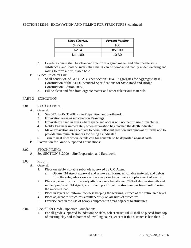
SECTION 312316 - EXCAVATION AND FILLING FOR STRUCTURES: continued
312316-2 81799_8220_312316
Sieve Size/No. Percent Passing
⅜ inch 100
No. 4 85‐100
No. 100 10‐30
2. Leveling course shall be clean and free from organic matter and other deleterious substances, and shall be such nature that it can be compacted readity under watering and rollng to form a firm, stable base.
B. Select Structural Fill: 1. Shall consist of of KDOT AB-3 per Section 1104 – Aggregates for Aggregate Base
Construction of the KDOT Standard Specifications for State Road and Bridge Construction, Edition 2007.
2. Fill be clean and free from organic matter and other deleterious materials.
PART 3 - EXECUTION
3.01 EXCAVATION: A. General:
1. See SECTION 312000- Site Preparation and Earthwork. 2. Excavation areas as indicated on Drawings. 3. Excavate by hand in areas where space and access will not permit use of machines. 4. Notify Engineer immediately when excavation has reached the depth indicated. 5. Make excavation area adequate to permit efficient erection and removal of forms and to
provide minimum clearances for filling as indicated. 6. Trim to neat lines where details call for concrete to be deposited against earth.
B. Excavation for Grade Supported Foundations:
3.02 STOCKPILING: A. See SECTION 312000 – Site Preparation and Earthwork.
3.03 FILL: A. General:
1. Place on stable, suitable subgrade approved by CM Agent. a. Obtain CM Agent approval and remove all forms, unsuitable material, and debris
from the subgrade or excavation area prior to commencing placement of any fill. 2. Place adjacent to structures only after concrete has attained 70% of design strength and,
in the opinion of CM Agent, a sufficient portion of the structure has been built to resist the imposed load.
3. Place in layers of uniform thickness keeping the working surface of the entire area level. 4. Place adjacent to structures simultaneously on all sides of structures. 5. Exercise care in the use of heavy equipment in areas adjacent to structures
3.04 Backfill for Grade Supported Foundations. 1. For all grade supported foundations or slabs, select structural ill shall be placed from top
of existing clay soil to bottom of levelling course, except if this distance is less than 12

SECTION 312316- EXCAVATION AND FILLING FOR STRUCTURES: continued
81799_8220_312316 312316-3
inches, then contractor shall over-excavate to provide a minimum of 12 inches of select structural fill beneath the levelling course.
2. Prepare exposed soil subgrade in accordance with SECTION 312313 - Subgrade Preparation.
3. Over excavation and backfill limits shall extend outward at least 2 feet from the base of the wall and then upward on a 1H:2V slope.
B. Compaction Testing: 1. See SECTION 312000 – Site Preparation and Earthwork for testing methods and
minimum testing frequency C. Equipment:
1. See SECTION 312000 – Site Preparation and Earthwork.
3.05 DISPOSAL OF WASTE MATERIALS AND DEBRIS: A. Disposal of Waste Materials and Debris shall be in accordance with SECTION 312000 – Site
Preparation and Earthwork. END OF SECTION 312316

81799_8110/8220_312333 312333-1
SECTION 312333 - TRENCHING AND BACKFILLING FOR UTILITIES
PART 1 - GENERAL
1.01 SUMMARY: A. This Section includes:
1. Excavation, sheeting, bracing and all operations necessary for the preparation of trenches for bedding of pipes and pipe appurtenances, conduit and buried cable.
2. Pipe embedments and encasements. 3. Filling (under, adjacent, and above pipes, conduits and buried cables) of trenches.
B. Related Work Specified Elsewhere: 1. Pressure Pipe for Potable Water Systems: SECTION 331100. 2. Gravity Pipe: SECTION 333100. 3. Pipe Installation: SECTION 331150.
1.02 REFERENCES: A. Applicable Standards:
1. American Society for Testing and Materials (ASTM): (Equivalent AASHTO standards may be substituted as approved.) a. C88 - Test Methods for Soundness of Aggregates by Use of Sodium Sulfate or
Magnesium Sulfate. b. D1241 - Materials for Soil-Aggregate Subbase, Base, and Surface Courses. c. D1556 - Test Method for Density and Unit Weight of Soil in Place by the Sand-
Cone Method. d. D1557 - Test Method for Laboratory Compaction Characteristics of Soil Using
Modified Effort (56,000 ft-lbf/ft3 (2,700 kN�m/m3)). e. D2167 - Test Method for Density and Unit Weight of Soil in Place by the Rubber
Balloon Method. f. D2922 - Density of Soil and Soil-Aggregate in Place by Nuclear Method (Shallow
Depth). g. D3017 - Test Method for Moisture Content of Soil and Rock in Place by Nuclear
Methods (Shallow Depth). h. D4253 - Test Methods for Maximum Index Density and Unit Weight of Soils using
a Vibratory Table. i. D4254 - Test Method for Minimum Index Density and Unit Weight of Soils and
Calculation of Relative Density. j. D4318 - Test Methods for Liquid Limit, Plastic Limit, and Plasticity Index of Soils. k. STP 479 - Special Procedures for Testing Soil and Rock for Engineering Purposes,
5th Edition, "Burmister Method." 2. U.S. Department of Interior, Bureau of Reclamation (USBR):
a. Earth Manual, 2nd Edition, Designation E-12, Relative Density of Cohesionless Soils, Alternate Method.
3. American Association of State Highway and Transportation Officials (AASHTO): a. T 99 (Method C) - Moisture-Density Relations of Soils Using a 2.5-kg (5.5-lb)
Rammer and a 305-mm (12-in) Drop. 4. Kansas Department of Transportation (KDOT) Standard Specifications for State Road
and Bridge Construction, Edition 2007. a. Section 151 – Compaction Equipment b. Section 1107 – Aggregates for Backfill c. Section 1115 – Test Methods for Division 1100

SECTION 312333- TRENCHING AND BACKFILLING FOR UTILITIES: continued
312333-2 81799_8110/8220_312333
1.03 QUALITY ASSURANCE: A. Sampling and Testing:
1. Testing shall conform to Section 1115 – Test Methods for Division 1100 – Aggregates of the KDOT Standard Specifications for State Road and Bridge Construction, Edition 2007.
PART 2 - PRODUCTS
2.01 MATERIALS: A. Definitions and classifications of materials used in this Section are stated in PART 3 -
EXECUTION this Section.
PART 3 - EXECUTION
3.01 TRENCHING: A. General:
1. Excavate all materials within the specified limits for excavation. 2. Perform excavation by any recognized method of good practice to complete the Work in
the most expeditious manner in conformance with specified requirements. 3. Take precautions to ensure no damage to existing facilities, undergorund utilities,
equipment, or other work. B. Equipment and Methods:
1. Types of equipment and methods may be at Subcontractor’s option, where structures or other facilities are not endangered.
2. Maximum length of open trench shall be limited to 50 feet in advance and to 50 feet behind pipe installation except as approved by Owner’s representative or local authority.
C. Side Walls: 1. Make vertical or slope within specified trench width limitations below a horizontal plane
12 inches above top of pipe. 2. Make vertical or sloped (stepped) as required for stability, above a horizontal plane 12
inches above top of pipe. 3. Excavate without undercutting. 4. Sheet and brace where necessary.
D. Trench Depth: 1. Depth shall be sufficient to provide the minimum bedding requirements for the pipe
being placed. 2. Do not exceed that indicated where conditions of bottom are satisfactory. 3. Increase depth as necessary to remove unsuitable supporting materials. Unsuitable
materials shall be defined as mud, muck, frozen earth, and material that is not free of debris, roots, organic matter, refuse, ashes, and cinders.
E. Trench Bottom: 1. Protect and maintain when suitable natural materials are encountered. 2. Remove rock fragments and materials disturbed during excavation or raveled from trench
walls. 3. Restoring overexcavation:
a. Restore overexcavation of depth 6 inches or less with trench stabilization material. b. Restore overexcavation of depth greater than 6 inches with structural fill. c. Correct at no extra cost to Owner when trench is overexcavated without authority or
to stabilize bottom rendered unsuitable through negligence or improper operations.

SECTION 312333 - TRENCHING AND BACKFILLING FOR UTILITIES: continued
81799_8110/8220_312333 312333-3
F. Trench Width: 1. Excavate trench to a width which will permit satisfactory jointing of the pipe and
thorough tamping of the bedding. 2. For single pipe installation, maintain trench widths in accordance with the Project
Drawings. 3. For multiple pipe installations, maintain trench widths below a plane 12 inches above the
top of the largest pipe as follows: Trench Clearances
Nominal Pipe Size Minimum From Maximum From of Outside Pipe Outside Pipe Outside Pipe Less than 24" 6" 12"
4. Maximum width shall be as near the minimum specified as can be controlled by construction equipment and methods used.
G. Trenching in Fill Areas: Perform after compacted fill has reached an elevation of not less than 1 foot above the top of the largest pipe in the trench.
3.02 PIPE EMBEDMENTS AND ENCASEMENTS: A. Granular Pipe Embedment: Gradation shall conform to the following for water main and
culverts: 1. Granular pipe embedment shall be Type PB-1 as defined in Section 1107 – Aggregates
for Backfill of the KDOT Standard Specifications for State Road and Bridge Construction, Edition 2007. Type PB-1 aggregate shall be used with a filter fabric.
2. Placement: Place granular embedment as follows: a. Level bottom layer at proper grade to receive and uniformly support pipe barrel
throughout its length. b. Form shallow depression under each joint to facilitate grouting. c. Form depression under each joint such that no part of bell or coupling is in contact
with trench when pipe is placed in position. d. Add second layer simultaneously to both sides of the pipe with care to avoid
displacement. e. Complete promptly after completion of jointing operations and approval to
proceed. f. Substitute for any part of earth fill to within 2 feet of proposed final grade at
Subcontractor’s option.
3.03 TRENCH BACKFILL: A. General:
1. Complete placement promptly upon completion of pipe embedment. 2. Use hand methods to a horizontal plane 12 inches above top of pipe barrel, bell and
coupling for conduit or duct banks. 3. Use approved mechanical methods where hand fill is not required. 4. Until compacted depth over conduit exceeds 3 feet, do not drop fill material over 5 feet.
Then distance may be increased 2 feet for each additional foot of cover. B. Granular Bedding
1. Install granular pipe bedding at the depths, widths and thickness as indicated on drawings.
2. Compact pipe bedding and dig bell holes so that the pipe is uniformly supported for its entire length and will be true to line and grade.

SECTION 312333- TRENCHING AND BACKFILLING FOR UTILITIES: continued
312333-4 81799_8110/8220_312333
3. After pipe has been brought to grade, aligned, and placed in final position, deposit and densify by shovel slicing sufficient bedding material under the pipe haunches and on each side of the pipe to hold the pipe in proper position during subsequent pipe jointing, bedding and backfill operations. Place bedding uniformly on each side of the pipe to prevent lateral displacement.
C. Earthen Backfill: 1. To be used in nonpaved areas.
D. Trench Fill: 1. Trench backfill beneath paved areas shall be SB-3 per KDOT Section 1107 – Aggregates
for Backfill. 2. Trench backfill in all other areas shall consist of job excavated material. 3. Placement and Compaction:
a. Structural fill shall be placed in loose lifts not to exceed 9 inches. b. Compact structural fill to 95% of Modified Proctor Density (ASTM D1557).
E. Compaction Testing: 1. The method of in-place compaction testing, including density and moisture content, shall
be as follows: a. Density - Cohesive materials: ASTM D2922. b. Density - Cohesionless materials: ASTM D2922. c. Moisture Content: ASTM D3017.
2. The minimum frequency of in-place compaction testing including density and moisture content will be as follows: a. At least one test for every 100 square feet per lift in structural fill. b. At least one test per lift if area of placement is less than 100 square feet. c. At least one test when Subcontractor suspects the quality of moisture control or
effectiveness of compaction. 3. Fill failing to meet required densities shall be removed or scarified and recompacted as
necessary to achieve specified results. 4. Removal of in-place material and replacement with approved new material will be
required if scarifying and recompaction do not produce the required densities. F. Equipment:
1. Equipment shall conform to Section 151 – Compaction Equipment of the KDOT Standard Specifications for State Road and Bridge Construction, Edition 2007.
END OF SECTION 312333.

81799_8110_321100 321100-1
DIVISION 32 – EXTERIOR IMPROVEMENTS SECTION 321100 - CRUSHED ROCK BASE AND SURFACE COURSES
PART 1 - GENERAL
1.01 SUMMARY: A. This Section includes crushed rock base and surface courses and method of placement for
gravel road and graveled areas. B. Related Work Specified Elsewhere:
1. Site Preparation and Earthwork: SECTION 312000. 2. Subgrade Preparation: SECTION 312313.
1.02 REFERENCES: A. Applicable Standards:
1. American Society for Testing and Materials (ASTM): Equivalent AASHTO standards may be substituted as approved. a. C29 –Test Method for Bulk Density (“Unit Weight”) and Voids in Aggregate. b. C88 Test Method for Soundness of Aggregates by use of Sodium Sulfate or
Magnesium Sulfate. c. C117 – Test Method for Materials Finer than 75-mm (No. 200) Sieve in Mineral
Aggregates by Washing. d. C131 – Test Method for Resistance to Degradation of Small-Size Coarse Aggregate
by Abrasion and Impact in the Los Angeles Machine. e. C136 – Test Method for Sieve Analysis of Fine and Coarse Aggregates. f. D75 – Practice for Sampling Aggregates. g. D1557 - Test Method for Laboratory Compaction Characteristics of Soil Using
Modified Effort (56,000 ft-lbf/ft3 (2,700 kNm/m3)). h. D2419 – Test Methods for Sand Equivalent Value of Soils and Fine Aggregate. i. D2922 – Test Methods for Density of Soil and Soil-Aggregate In-Place by Nuclear
Methods (Shallow Depth). j. D3017 – Test Method for Water Content of Soil and Rock In Place by Nuclear
Methods (Shallow Depth). k. D3665 – Practice for Random Sampling of Construction Materials. l. D4318 – Test Methods for Liquid Limit, Plastic Limit, and Plasticity Index of
Soils. 2. Kansas Department of Transportation (KDOT) Standard Specifications for State Road
and Bridge Construction, Edition 2007. a. Section 301 – Equipment b. Section 303 – Aggregate Base Course and Stabilized Shoulders c. Section 307 – Light Type Surfacing d. Section 308 – Surfacing for Side Roads and Entrances e. Section 1105 – Aggregates for Aggregate Base Construction f. Section 1112 – Aggregates for Surfacing or Resurfacing g. Section 1117 – Methods of Test for Section 1100 – Aggregates
3. 90P-232-R2 Kansas Department of Transportation (KDOT) Special Provision to the Standard Specifications, Edition of 2007. a. Subsection 1116
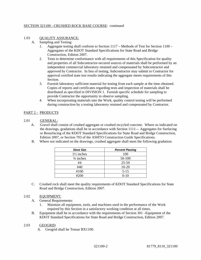
SECTION 321100 - CRUSHED ROCK BASE COURSE: continued
321100-2 81779_8110_321100
1.03 QUALITY ASSURANCE: A. Sampling and Testing:
1. Aggregate testing shall conform to Section 1117 – Methods of Test for Section 1100 – Aggregates of the KDOT Standard Specifications for State Road and Bridge Construction, Edition 2007.
2. Tests to determine conformance with all requirements of this Specification for quality and properties of all Subcontractor-secured sources of materials shall be performed by an independent commercial laboratory retained and compensated by Subcontractor and approved by Contractor. In lieu of testing, Subcontractor may submit to Contractor for approval certified state test results indicating the aggregate meets requirements of this Section.
3. Furnish laboratory sufficient material for testing from each sample at the time obtained. Copies of reports and certificates regarding tests and inspection of materials shall be distributed as specified in DIVISION 1. Furnish specific schedule for sampling to provide Contractor the opportunity to observe sampling.
4. When incorporating materials into the Work, quality control testing will be performed during construction by a testing laboratory retained and compensated by Contractor.
PART 2 - PRODUCTS
2.01 GENERAL: A. Gravel shall consist of crushed aggregate or crushed recycled concrete. Where so indicated on
the drawings, gradations shall be in accordance with Section 1111— Aggregates for Surfacing or Resurfacing of the KDOT Standard Specifications for State Road and Bridge Construction, Edition 2007, or Section 703 of the ASHTO Construction Guide Specifications.
B. Where not indicated on the drawings, crushed aggregate shall meet the following gradation:
Sieve Size Percent Passing
1½ inches 100 ¾ inches 50-100
#4 25-50 #40 10-20
#100 5-15 #200 0-10
C. Crushed rock shall meet the quality requirements of KDOT Standard Specifications for State
Road and Bridge Construction, Edition 2007.
2.02 EQUIPMENT: A. General Requirements:
1. Maintain all equipment, tools, and machines used in the performance of the Work required by this Section in a satisfactory working condition at all times.
B. Equipment shall be in accordance with the requirements of Section 301 –Equipment of the KDOT Standard Specifications for State Road and Bridge Construction, Edition 2007.
2.03 GEOGRID A. Geogrid shall be Tensar BX1100.

SECTION 321100 - CRUSHED ROCK BASE COURSE: continued
81799_8110_321100 321100-3
PART 3 - EXECUTION
3.01 GENERAL REQUIREMENTS: A. Stockpiles:
1. Clear and level storage sites prior to stockpiling. 2. Place in the manner and at locations designated by Contractor providing separate
stockpiles for materials from separate sources. 3. Prevent aggregate from segregating during placement, storage, and handling at
stockpiles. B. Cold-Weather Limitations:
1. Base course construction shall be prohibited when atmospheric temperature is below 35F, unless approved in writing by Contractor.
2. Do not place base course on frozen subgrade. 3. Protect base course and subgrade in freezing weather and repair areas damaged by
freezing by reshaping and recompacting. C. Preparation of Subgrade:
1. Clean of all foreign substances. 2. Subcontractor will inspect for adequate compaction and surface tolerances as specified in
SECTION 312313 – Subgrade Preparation. 3. Correct any ruts or soft yielding spots or any areas with inadequate compaction.
D. Grade Control: Establish and maintain grade by means of grade stakes placed in lanes parallel to the centerline of the area to have crushed rock and spaced so string lines may be stretched between stakes, or by other method as approved by Contractor.
3.02 PLACING OF MATERIALS: A. Place and compact materials in accordance with the requirements of Section 303 – Aggregate
Base Course and Stabilized Shoulders, Section 307 – Light Type Surfacing, and Section 308 – Surfacing for Side Roads and Entrances of the KDOT Standard Specifications for State Road and Bridge Construction, Edition 2007.
B. Degree of Compaction: 1. Compaction Testing:
a. The method of in-place compaction testing shall be as follows: (1) Density - ASTM D2922. (2) Moisture Content - ASTM D3017.
b. The minimum frequency of density tests will be as follows: (1) At least one test every 100 feet along a roadway or one test every 1,200
square yards of base and surface course placed. (2) At least one test when Contractor suspects the quality of moisture control or
effectiveness of compaction.

SECTION 321100 - CRUSHED ROCK BASE COURSE: continued
321100-4 81779_8110_321100
2. Compact each layer to at least 95% of Standard Proctor Density ASTM D698. 3. If ASTM D2922 is used for field density testing, the gauge shall be field calibrated in
accordance with paragraph 4 of ASTM D2922. Calibration tests shall be conducted on the first load of material placed that meets the density requirements. Use of ASTM D2922 results in a wet unit weight, and when using this method, ASTM D3017 shall be used to determine the moisture content of the material. The calibration curve furnished with the moisture gauges shall be checked as described in paragraph 7 of ASTM D3017. The calibration checks of both the density and moisture gauges shall be made at the beginning of the job and at intervals as determined by Contractor.
4. Remove or scarify and recompact base course failing to meet required densities. 5. Removal of in-place material and replacement with approved new material will be
required if scarifying and recompaction do not produce the required densities. C. Smoothness Test:
1. Surface shall show no deviation in excess of 3/8-inch in any 10 feet when tested with a 10-foot straightedge applied parallel with and at right angles to the centerlines of the paved area.
2. Correct any deviation in excess of this amount by loosening, adding or removing material, reshaping, watering, and compacting as requested by Contractor. In no case shall the addition of thin layers of material be added to the top layer of base course to meet grade. If the elevation of the top layer is 1/2 inch or more below grade, the top layer of base shall be scarified to a depth of at least 3 inches, new material added, and the layer shall be blended and recompacted to bring it to grade. If the finished surface is above plan grade, it shall be cut back to grade and rerolled.
D. Geogrid: 1. Place directly on exposed subgrade. Overlap adjacent roll a minimum of one foot and
cable tie at 8 foot maximum intervals. 2. Anchor edges of geogrid with staples in accordance with the manufacturers
recommendations.
3.03 MAINTENANCE: A. Maintain finished base course in a moist condition until the next layer is placed in a condition
satisfactory to Contractor. B. Contractor’s approval of base course at the time of its completion does not relieve
Subcontractor of the requirement to maintain base course until such time as the overlying material is in place.
END OF SECTION 321100

81779_8110_321126 321126-1
SECTION 321126 - HOT-MIX ASPHALTIC CONCRETE PAVEMENT
PART 1 – GENERAL
1.01 SUMMARY: A. This Section includes hot-mix asphaltic concrete pavement materials, bituminous prime coat,
bituminous tack coat, equipment, placement, and testing. B. Related Work Specified Elsewhere:
1. Site Preparation and Earthwork: SECTION 312000. 2. Subgrade Preparation: SECTION 312313. 3. Crushed Rock Base and Surface Courses: SECTION 321100. 4. Bituminous Prime Coat: SECTION 321214. 5. Bituminous Tack Coat: SECTION 321215.
1.02 REFERENCES: A. Applicable Standards:
1. American Society for Testing and Materials (ASTM): Equivalent AASHTO standards may be substituted as approved. a. C29 - Test Method for Unit Weight and Voids in Aggregate. b. C117 - Test Method for Material Finer than 75 m (No. 200) Sieve in Mineral
Aggregates by Washing. c. C131 - Test Method for Resistance to Degradation of Small-Size Coarse Aggregate
by Abrasion and Impact in the Los Angeles Machine. d. C136 - Test Method for Sieve Analysis of Fine and Coarse Aggregates. e. C183 - Practice for Sampling and the Amount of Testing of Hydraulic Cement. f. D75 - Practice for Sampling Aggregates. g. D140 - Practice for Sampling Bituminous Materials. h. D242 - Mineral Filler for Bituminous Paving Mixtures. i. D244 - Test Methods for Emulsified Asphalts. j. D977 - Emulsified Asphalt. k. D979 - Practice for Sampling Bituminous Paving Mixtures. l. D1073 - Fine Aggregate for Bituminous Paving Mixtures. m. D5581 - Test Method for Resistance to Plastic Flow of Bituminous Mixtures Using
Marshall Apparatus (6-inch-diameter specimen). n. D1560 - Test Methods for Resistance to Deformation and Cohesion of Bituminous
Mixtures by Means of the Hveem Apparatus. o. D1561 - Practice for Preparation of Bituminous Mixture Test Specimens by Means
of California Kneading Compactor. p. D2397 - Cationic Emulsified Asphalt. q. D2489 - Test Method for Degree of Particle Coating of Bituminous-Aggregate
Mixtures. r. D2950 - Test Method for Density of Bituminous Concrete in Place by Nuclear
Method. 2. American Association of State Highway and Transportation Officials (AASHTO):
a. T30 - Mechanical Analysis of Extracted Aggregate. b. T102 - Spot Test of Asphaltic Materials. c. M226 - Viscosity Graded Asphalt Cement.

SECTION 321126 - HOT-MIX ASPHALTIC CONCRETE PAVEMENT: continued
321126-2 81779_8110_321126
3. Federal Specifications (FS): a. SS-A-706 - Asphalt, Petroleum: Road and Pavement Construction (Asphalt
Cement). 4. Kansas Department of Transportation (KDOT) Standard Specifications for State Road
and Bridge Construction, Edition 2007. a. Section 155 – Asphalt Surfacing and Asphalt Recycling Equipment b. Division 600 – Flexible Pavement c. Division 1200 – Asphalt Material
1.03 QUALITY ASSURANCE: A. Sampling and Testing:
1. When incorporating materials into the Work, quality control testing will be performed during construction by a testing laboratory retained and compensated by Contractor.
2. Testing shall conform to Section 602 – Methods of Test for Section 1200 – Bituminous Materials of the KDOT Standard Specifications for State Road and Bridge Construction, Edition 2007.
1.04 JOB CONDITIONS: A. Weather Limitations:
1. Prime coat, tack coat or hot-mix asphaltic concrete shall not be mixed or placed when the ambient temperature is below 40ºF.
2. Apply tack coat only when base course is dry enough to permit uniform distribution and desired penetration.
PART 2 - PRODUCTS
2.01 EQUIPMENT: A. Equipment shall conform to the requirements of Section 155–Asphalt Surfacing and Asphalt
Recycling Equipment of the KDOT Standard Specifications for State Road and Bridge Construction, Edition 2007.
2.02 MATERIALS: A. Bituminous concrete mix shall conform to the requirements for Class A hot-mix asphalt
commercial grade as specified in Section 611 – Hot Mix Asphalt – Commercial Grade of the Special Provisions of KDOT Standard Specifications for State Road and Bridge Construction, Edition 2007.
PART 3 - EXECUTION
3.01 APPLICATION: A. Preparation of mixture, transportation of mixture, bituminous mixture placement, compaction
of mixtures, joint material and construction, protection of pavement, surface tolerances, and testing shall conform to the requirements of Section 601 – Asphalt Application Temperatures and Section 602 – Hot Mix Asphalt (HMA) Construction of the KDOT Standard Specifications for State Road and Bridge Construction, Edition 2007.
END OF SECTION 321126

SECTION 321214 - BITUMINOUS PRIME COAT
PART 1 - GENERAL
1.01 SUMMARY: A. This Section includes hot bituminous prime coat over previously prepared, crushed-rock base
course. B. Related Work Specified Elsewhere:
1. Site Preparation and Earthwork: SECTION 312000. 2. Subgrade Preparation: SECTION 312313. 3. Crushed-Rock Base and Surface Courses: SECTION 321100. 4. Bituminous Tack Coat: SECTION 321215.
1.02 REFERENCES:
A. Applicable Standards: 1. KDOT Standard Specifications for State Road and Bridge Construction, Edition 2007.
a. Section 612 – Bituminous Prime Coat b. Section 1206 – General Requirements for Section 1200 – Bituminous Materials c. Section 1207 – Methods of Test for Section 1200 – Bituminous Materials
PART 2 - PRODUCTS
2.01 BITUMINOUS MATERIAL:
A. Bituminous material shall conform Division 1200 – Asphalt Materials of the KDOT Standard Specifications for State Road and Bridge Construction, Edition 2007.
2.02 EQUIPMENT:
A. General Requirements: 1. Furnish and maintain all equipment, tools, and machines used in the performance of the
Work in satisfactory working condition at all times. 2. Equipment shall be subject to approval of Contractor.
B. Bitumen distributor shall be as follows: 1. Designed and equipped so as to distribute bituminous material uniformly at even heat on
variable widths of surface and to distribute the bituminous material at readily determined and controlled rates from 0.05 to 2.0 gallons per square yard.
2. Have pneumatic tires of such width and number that the load produced on the base surface does not exceed 650 pounds per inch of tire width.
3. Have a pressure range of 25 to 75 psi. 4. Allowable variation from any specified rate shall not exceed 5%. 5. Equipped for circulation and agitation of the bituminous material during the heating
process. C. Distributor Equipment shall include the following:
1. Bitumen pump. 2. Tachometer. 3. Pressure gauges. 4. Volume-measuring device. 5. Thermometer for temperature of tank contents. 6. Hose attachment to apply materials to spots unavoidably missed by distributor.
D. Heating Equipment shall include the following:
81799_8110_321214 321214-1
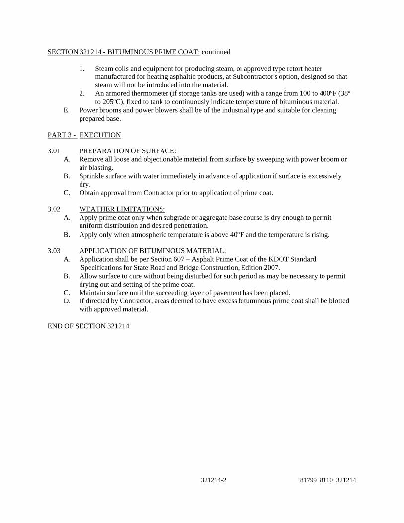
SECTION 321214 - BITUMINOUS PRIME COAT: continued
1. Steam coils and equipment for producing steam, or approved type retort heater manufactured for heating asphaltic products, at Subcontractor's option, designed so that steam will not be introduced into the material.
2. An armored thermometer (if storage tanks are used) with a range from 100 to 400ºF (38º to 205ºC), fixed to tank to continuously indicate temperature of bituminous material.
E. Power brooms and power blowers shall be of the industrial type and suitable for cleaning prepared base.
PART 3 - EXECUTION
3.01 PREPARATION OF SURFACE:
A. Remove all loose and objectionable material from surface by sweeping with power broom or air blasting.
B. Sprinkle surface with water immediately in advance of application if surface is excessively dry.
C. Obtain approval from Contractor prior to application of prime coat.
3.02 WEATHER LIMITATIONS: A. Apply prime coat only when subgrade or aggregate base course is dry enough to permit
uniform distribution and desired penetration. B. Apply only when atmospheric temperature is above 40F and the temperature is rising.
3.03 APPLICATION OF BITUMINOUS MATERIAL:
A. Application shall be per Section 607 – Asphalt Prime Coat of the KDOT Standard Specifications for State Road and Bridge Construction, Edition 2007.
B. Allow surface to cure without being disturbed for such period as may be necessary to permit drying out and setting of the prime coat.
C. Maintain surface until the succeeding layer of pavement has been placed. D. If directed by Contractor, areas deemed to have excess bituminous prime coat shall be blotted
with approved material.
END OF SECTION 321214
321214-2 81799_8110_321214

SECTION 321215 - BITUMINOUS TACK COAT
PART 1 - GENERAL
1.01 SUMMARY: A. This Section includes hot bituminous tack coat over previously prepared bituminous base
course. B. Related Work Specified Elsewhere:
1. Hot Mix Asphaltic Concrete Pavement: SECTION 321126. 2. Bituminous Prime Coat: SECTION 321214.
1.02 REFERENCES:
A. Applicable Standards: 1. American Society for Testing and Materials (ASTM):
a. D140 – Practice For Sampling Bituminous Materials. b. D633 – Volume Correction Table for Road Tar. c. D977 – Emulsified Asphalt. d. D1250 – Guide for Petroleum Measurement Tables. e. D2028 – Cutback Asphalt (Rapid-Curing Type). f. D2397 – Cationic Emulsified Asphalt.
2. American Association of State Highway and Transportation Officials (AASHTO): a. M52 – Tar for Use in Road Construction.
3. Asphalt Institute (AI): a. MS-6 Table IV-3 – Temperature-Volume Correction for Emulsified Asphalts.
4. Kansas Department of Transportation (KDOT) Standard Specifications for State Road and Bridge Construction, Edition 2007.
1.03 QUALITY ASSURANCE:
A. Sampling and Testing: 1. Submit certified state test results indicating that the aggregate meets Specification
requirements to Contractor for approval.
PART 2 - PRODUCTS
2.01 BITUMINOUS MATERIAL: 1. Bitumionus material shall conform Division 1200 – Asphalt Materials of the KDOT
Standard Specifications for State Road and Bridge Construction, Edition 2007.
2.02 EQUIPMENT: A. General Requirements:
1. Furnish and maintain all equipment, tools, and machines used in the performance of the Work required by this Section in satisfactory working condition at all times.
2. Equipment shall be subject to approval of Contractor. B. Bitumen Distributor:
1. See Section 321214 – Bituminous Prime Coat.
PART 3 - EXECUTION
3.01 PREPARATION OF SURFACE:
81799_8110_321215 321215-1

SECTION 321215 - BITUMINOUS TACK COAT: continued
A. Remove all loose and objectionable material from surface by sweeping with a power broom and/or airblasting.
B. Obtain approval from Contractor prior to application of tack coat. 3.02 WEATHER LIMITATIONS:
A. Apply tack coat only when base course is dry enough to permit uniform distribution and desired penetration.
B. Apply only when atmospheric temperature is above 40oF and the temperature is rising. 3.03 APPLICATION OF BITUMINOUS MATERIAL:
A. Properly treat all spots unavoidably missed by distributor. B. Allow surface to cure without being disturbed for such period as may be necessary to permit
drying out and setting of the tack coat. C. Maintain surface until the succeeding layer of pavement has been placed. D. If directed by Contractor, areas deemed to have excess bituminous tack shall be blotted with
approved material. END OF SECTION 321215
321215-2 81799_8110_321215

81799_8110_323113 323113-1
SECTION 323113 - FENCES AND GATES
PART 1 - GENERAL
1.01 SUMMARY: A. This Section includes permanent chain-link fabric fence, gates, and related components.
1.02 REFERENCES: A. Applicable Standards:
1. American Society for Testing and Materials (ASTM): a. A123 - Zinc (Hot-Dip Galvanized) Coatings on Iron and Steel. b. A153 - Zinc Coating (Hot-Dip) on Iron and Steel Hardware. c. A392 - Zinc-Coated Steel Chain-Link Fence Fabric. d. A491 - Aluminum-Coated Steel Chain-Link Fence Fabric. e. A569 - Steel, Carbon (0.15 Maximum, Percent), Hot-Rolled Sheet and Strip,
Commercial Quality. f. B211/B211M - Aluminum-Alloy Bars, Rods, and Wire. g. B221/B221M - Aluminum-Alloy Extruded Bars, Rods, Wire, Shapes, and Tubes. h. C94/C94M - (2004a) Standard Specification for Ready-Mixed Concrete i. F668 - Poly(VinylChloride) (PVC)-Coated Steel Chain-Link Fence Fabric. j. F669 - Strength Requirements of Metal Posts and Rails for Industrial Chain-Link
Fence. k. F1083 - Pipe, Steel, Hot Dipped, Zinc-Coated (Galvanized) Welded, for Fence
Structures.
1.03 SUBMITTALS: A. Submit as specified in DIVISION 1. B. Includes, but not limited to, the following:
1. Product data: Manufacturer's technical data, specifications, and installation instructions for fence and gate posts, fabric, gates, and accessories.
2. Shop Drawings: Showing layout, location of fence, gates, posts, and including details illustrating fence height, sizes of posts, rails, braces, gates, hardware list, and accessories.
3. Mill certification that materials meet specifications of member size, strength, wall thickness, and coatings.
1.04 QUALITY ASSURANCE: A. Provide chain-link fences and gates as complete units, including necessary erection
accessories, fittings, and fastenings, from a single source or manufacturer.
PART 2 - PRODUCTS
2.01 ACCEPTABLE MANUFACTURERS: A. Subject to compliance with requirements, provide products of one of the following:
1. Galvanized Steel Fencing and Fabric: a. Allied Tube and Conduit Corp. b. Anchor Fence, Inc. c. Engineer-approved Equal
2. Motor-Operated Gates, Operators, and Controls: a. Tymetal Corp. b. Anchor Fence, Inc. c. Stanley Works.

323113-2 81799_8110_323113
d. Security Fabricators, Inc. e. Engineer-approved Equal
2.02 GENERAL: A. Fence height and gate width(s) for the perimeter of the plant shall be as indicated on the
Drawings. B. Dimensions indicated for pipe, roll-formed, and H-sections are outside dimensions, exclusive
of coatings.
2.03 FABRIC: A. Steel Fabric:
1. No. 9 gage, 2-inch diamond-mesh steel, chain-link fabric. Furnish 1-piece fabric widths for fencing.
2. Galvanized: Conform to ASTM A392 with zinc coating, Class 1, 1.2 ounces minimum per square foot of wire surface.
3. Bottom selvage twisted and top selvage knuckled for fabric.
2.04 FRAMING AND ACCESSORIES: A. Steel Framework:
1. General: Galvanized steel, ASTM F1083 or ASTM A123, with not less than 1.8-ounce zinc per square foot of surface, or steel conforming to ASTM A569 externally triple-coated with hot-dip galvanizing at 1.0 ounce/square foot, chromatic conversion coating and clear acrylic polyurethane and coated internally with zinc-rich coating.
2. Fittings and Accessories: Galvanized, ASTM A153, with zinc weights per Table I.
2.05 STEEL POSTS, TENSION WIRE, AND BRACES: A. Minimum size and weight of steel components shall be as follows:
1. Posts for Steel Fabric: a. End, Angle, Corner, or Pull Posts: 2.875 inches od at 5.79 pounds per foot, unless
otherwise indicated on Drawings. b. Line Posts: 2.375 inches od at 3.65 pounds per foot, unless otherwise indicated on
Drawings. c. In lieu of pipe specified above, steel pipe conforming to ASTM A569 of greater
strength but less wall thickness, will be acceptable. 2. Gate Posts:
a. Furnish 4 inches od at 9.11 pounds per foot gate posts, unless otherwise indicated on Drawings.
3. Tension Wire: No. 7 gage coiled spring wire, metal and finish to match fabric. Locate at bottom and top of fabric.
4. Wire Ties: 11-gage galvanized steel to match fabric core material.
2.06 BARBED WIRE AND SUPPORTING ARMS: A. Supporting Arms:
1. One for each post. 2. Constructed for attaching three rows of barbed wire to each arm and designed as a
weathertight closure cap where tubular posts are used. 3. Designed for 300 pound minimum pull-down load. 4. Attached to steel posts or integral with post top. 5. Provided with openings to receive top rail. 6. Pressed steel.
B. Barbed Wire:

SECTION 323113 -FENCES AND GATES: continued
81799_8110_323113 323113-3
1. Two-strand, 12-1/2-gage steel wire with 14-gage, 4-point barbs 5 inches oc intervals. 2. Metal and finish to match fabric. 3. Three rows required.
2.07 CONCRETE: A. Concrete shall conform to ASTM C94/C94M. Mix shall be designed to obtain concrete with a
minimum 28-day compressive strength of 3,000 psi.
2.08 CRUSHED ROCK: A. Gradation of 3/4-inch to 1-inch sizes.
PART 3 - EXECUTION
3.01 PREPARATION: A. Grading: Perform final grading prior to installation of fence. B. Placing Crushed Rock:
1. Place prior to installing fabric. 2. Place to a depth of 6 inches below grade and 2-foot width, centered along post lines.
3.02 INSTALLATION: A. Fence:
1. Follow general contour of ground and properly align. Install as indicated. 2. Posts:
a. Set in concrete bases. Trowel-finish tops of footings and dome to direct water away from posts.
b. Temporarily brace until concrete in bases has set. c. Install plumb and in straight alignment. d. Space 10 feet center-to-center maximum. e. Install pull posts every 300 feet if no corner posts are encountered in that distance. f. Install corner posts at changes in direction of 30o or more. g. Install pull posts at changes in direction of 10o to 30o. h. Install pull posts at all abrupt changes in grade.
3. Post Bracing: a. Install at each end, pull and gate post, and each side of each corner post. b. Install after concrete in post bases has set. c. Install so posts are plumb when diagonal rod is under tension.
4. Tension Wire: Weave through the fabric and tie to each post with minimum 7-gage galvanized wire to match fabric finish.
5. Fabric: a. Stretch taut with equal tension on each side of line posts. b. Install fabric on security side of fence and anchor to framework so that fabric
remains in tension after pulling force is released. c. Use U-shaped wire, conforming to diameter of pipe to which attached, clasping pipe
and fabric firmly with ends twisted at least two full turns. Bend ends of wire to minimize hazard to persons or clothing.
d. Fasten fabric to steel posts with wire ties spaced 12 inches oc maximum. e. Fasten fabric to tension wire using 11-gage hog rings of same material and finish as
fabric wire, spaced at 24 inches oc. 6. Stretcher Bars:

323113-4 81799_8110_323113
a. Thread through or clamp to fabric 4 inches oc. b. Secure to posts with metal bands spaced 15 inches oc maximum. c. Install at each gate, pull and end post, and each side of corner post.
7. Post Tops and Barbed Wire Supporting Arms: Install on each post. 8. Barbed Wire:
a. Attach three rows to each barbed wire supporting arm. Pull wire taut and fasten securely to each arm.
b. Install three rows above fabric and on extended gate end members of swing gates. 9. Barbed Tape: Install in configurations indicated in accordance with manufacturer's
recommendations and securely fasten to fencing to prevent movement or displacement. 10. Fasteners: Install nuts for tension bands and hardware bolts on side of fence opposite
fabric side. (Peen ends of bolts or score threads to prevent removal of nuts). B. Repairing Damaged Coatings:
1. Repair any damaged coatings in the shop or field by recoating with compatible and similar coating.
2. Apply per manufacturer's recommendations. END OF SECTION 323113

81799_8110_329200 329200-1
SECTION 329200 - SEEDING PART 1 – GENERAL
1.01 SUMMARY: A. This Section includes seedbed preparation, seeding, mulching, and fertilizing of areas along
access road and/or disturbed by Contractor construction activities, and other miscellaneous soil stabilization practices.
B. Related work specified elsewhere: 1. Site Preparation and Earthwork – Section 312000. 2. Subgrade Preparation – Section 312313.
1.02 REFERENCES:
A. Applicable Standards: 1. American Society for Testing and Materials (ASTM): Equivalent AASHTO standards
may be substituted as approved. a. D977 - Emulsified Asphalt.
2. Kansas Department of Transportation (KDOT) Standard Specifications for State Road and Bridge Construction, Edition 2007. b. c. Section 903 - Seeding d. Section 901 – Erosion and Pollution Control e. Section 905 –Topsoil f. Section 902 – Fertilizer, Agricultural Limestone and Peat Moss g. Section 904 – Mulching h. Section 2103 – Seeds i. Section 2108 – Fertilizers j. Section 2110 – Mulching k. Section 2101 – Topsoil
3. Project Storm Water Pollution Prevention Plan (SWPPP). 1.03 SUBMITTALS:
A. Certificates: Includes, but not limited to, the following: 1. Certification from vendor that products specified in this section meet KDOT Standard
Specifications for State Road and Bridge Construction, Edition 2007 requirements. 2. Topsoil test results secured from the County Extension Agent.
1.04 JOB CONDITIONS:
A. Temporary Erosion and Sediment Controls: Subcontractor shall furnish, install, construct, and maintain temporary measures to control erosion and minimize the siltation of intermittent streams and the pollution of private properties. Temporary erosion and sediment control measures shall be in compliance with the Project SWPPP and shall be maintained until completion of Contract.

329200-2 81799_8110_329200
SECTION 329200 - SEEDING: continued
PART 2 - PRODUCTS
2.01 GENERAL: A. Seed:
1. Shall be mixed and certified a licensed dealer. 2. Mix shall consist of 80% Kentucky 31 Fescue and 20% Korean Lespedeza, by weight. B.
Topsoil shall be placed in accordance with Section 2101 – Topsoil of the KDOT Standard Specifications Seed shall be uniformly sown.
B. Fertilizer: 1. Shall be commercial fertilizer formula 13-13-13 conforming to applicable state fertilizer
laws. 2. Shall be uniform in composition, dry and free flowing. 3. Deliver to site in original unopened containers bearing the manufacturer’s guaranteed
analysis. C. Lime:
1. Shall be ground limestone containing not less than 85% of total carbonates and shall be ground so that 50% will pass the #100 sieve and 90% shall pass the #20 sieve.
D. Mulch: 1. Vegetative mulch shall be shredded cereal straw from the stalks of oats, rye, wheat, or barley. The straw will be free of prohibited weed seeds as stated in the State Seed Law; shall be relatively free of other noxious seeds; and shall be clean, bright, and sufficiently dry to spread uniformly.
PART 3 - EXECUTION
3.01 GENERAL: A. Execution, maintenance, and repair of all seeding, mulching, fertilizer, and erosion control
products shall be in accordance with the Project SWPPP.
3.02 VEGETATIVE RESTORATION A. Vegetative areas disturbed by construction activities shall be restored to equal or better
condition by the proper application of topsoiling, seed mixture, and protective mulch and maintaining said areas until a satisfactory stand of vegetation is established.
B. The contractor shall, at his own expense, contact the County Extension agent and secure a soil test of the topsoil. If recommended by the Agent, the topsoil shall be lime conditioned. Three copies of the test results shall be submitted to the CM Agent. Estimates of lime requirements are:
POUNDS OF LIMESTONE PER 1,000 SQUARE FEET pH Light sandy Soil Medium Sandy
Soil Loam and Silty
Loam Clay Loam
4.0 90 120 172 217 4.5 82 112 157 202 5.0 67 90 127 150 5.5 52 67 97 120 6.0 None None None None
C. Topsoil shall be placed in accordance with Section 2101 – Topsoil of the KDOT Standard
Specifications for State Road and Bridge Construction, Edition 2007. Minimum depth of topsoil shall be 6 inches.

81799_8110_329200 329200-3
D. Seed mix shall be applied at a rate of 200 pounds per acre. After applications, lightly rake
and water with a fine spray. E. Within 24 hours of seeding, mulch shall be spread evenly of the entire area at a rate of 2½
tons per acre. F. Fertilizer shall be applied at a rate of 20 pounds per 1,000 square feet. Apply after seed has
sprouted unless approved by CM Agent. G. Seeding shall be initiated as soon as practical after earthwork operations have ceased, but in no
case more than 14 days after such operations have ceased. H. Water seeded areas as necessary to prevent death or damage of seeds and new vegetation due
to lack of water, during the time period between seeding and when the vegetation becomes rooted in the soil and is growing in place.
END OF SECTION 329200

81799_8110/8220_331150 331150-1
SECTION 331150 - PIPE INSTALLATION
PART 1 - GENERAL
1.01 SUMMARY: A. This Section includes handling, installation and testing of pipe, fittings, specials, and
appurtenances as indicated or specified. B. Related Work Specified Elsewhere:
1. Gravity Pipe: SECTION 333100. 2. Pressure Pipe for Potable Water Systems: SECTION 331100. 3. Trenching and Backfilling for Utilities: SECTION 312333.
1.02 REFERENCES: A. Applicable Standards:
1. American Society for Testing and Materials (ASTM): a. D2321 - Underground Installation of Flexible Thermoplastic Sewer Pipe. b. D2774 – Standard Practice for Underground Installation of Thermoplastic Pressure
Piping. c. F1417 - Installation Acceptance of Plastic Gravity Sewer Lines Using Low-Pressure
Air. 2. American Water Works Association (AWWA):
a. C105 - Polyethylene Encasement for Ductile-Iron Pipe Systems. b. C600 - Installation of Ductile-Iron Water Mains and Their Appurtenances. c. C651- Disinfecting Water Mains. d. M23 - PVC Pipe - Design and Installation.
3. Federal Specifications (FS): a. SS-S-00210 - Sealing Compound, Preformed Plastic, For Expansion Joints and Pipe
Joints. 4. Kansas Department of Health and Environment (KDHE) Policies, General
Considerations, and Design Requirements for Public Water Supply Systems in Kansas, 2007 Edition. a. Chapter VIII – Distribution Systems b. Appendix C – Procedures for Pressure and Leakage Testing of Mains c. Appendix D – Water Main Disinfection Procedures
1.03 QUALITY ASSURANCE A. Procedures and Qualifications:
1. Butt Fused Joints for Polyethylene Pipe: a. Butt fused joint erection procedure shall be in accordance with pipe manufacturer’s
standards and erection equipment. b. Butt fused joint erection procedure and HDPE certifications shall be maintained
onsite and available for review prior to and during pipe installation.
1.04 DELIVERY, STORAGE AND HANDLING: A. Handle in a manner to ensure installation in sound and undamaged condition.
1. Do not drop or bump. 2. Use slings, lifting lugs, hooks, and other devices designed to protect pipe, joint elements,
linings, and coatings.

SECTION 331150 – PIPE INSTALLATION: continued
331150-2 81799_8110/8220_331150
B. Ship, move, and store with provisions to prevent movement or shock contact with adjacent units.
C. Handle with equipment capable of work with adequate factor of safety against overturning or other unsafe procedures.
D. Do not deliver precast concrete components to the job until concrete has attained at least 80 percent of the specified minimum design strength. Mix design and casting documentation may be used to verify that this requirement has been met.
PART 2 - PRODUCTS
2.01 PIPE AND ACCESSORIES: A. Specified in respective Sections, this Division.
PART 3 - EXECUTION 3.01 INSTALLATION - GENERAL:
A. Field Quality Control 1. Only applies to potable water pipe installation. 2. Perform all water supply and sanitary sewerage work under qualified direct supervision.
Supervisor must hold a current ODEQ Class D Water Works Operation Certification and have experience with materials and procedures required to complete the work, including protection of existing facilities such as transportation and other utility infrastructure.
B. Maintain an accurate record of location, size and direction of the pipelines, manholes, service connections, and other improvements, as installed in the field. 1. Locations shall use the pipeline stationing as shown on the plans or the distance from the
first downstream manhole. 2. Provide the record for incorporation into Record Drawings.
C. Use equipment, methods, and materials ensuring installation to lines and grades indicated. 1. Accomplish horizontal and vertical curve alignments with bends, bevels, and joint
deflections. 2. Oil/Water Drains:
a. Grade: ± ½” b. Alignment: ± 4”
D. Install pipe of size, materials, strength class, and joint type with embedment indicated for plan location.
E. Insofar as possible, commence laying at downstream end of line. F. Clean interior of all pipe, fittings, and joints prior to installation. Exclude entrance of foreign
matter during installation and at discontinuance of installation. 1. Remove water, sand, mud, and other undesirable materials from trench before removal of
end cap for potable water pipe. G. Close open ends of pipe with snug-fitting closures. H. Do not let water fill trench. Include provisions to prevent flotation should water control
measures prove inadequate. I. Brace or anchor as required to prevent displacement after establishing final position. J. Perform only when weather and trench conditions are suitable. Do not lay in water. K. Visually examine pipe while suspended and before lowering into trench for gouges, scratches,
and other defects. 1. Repair pipe in accordance with pipe manufacturer’s recommendations.
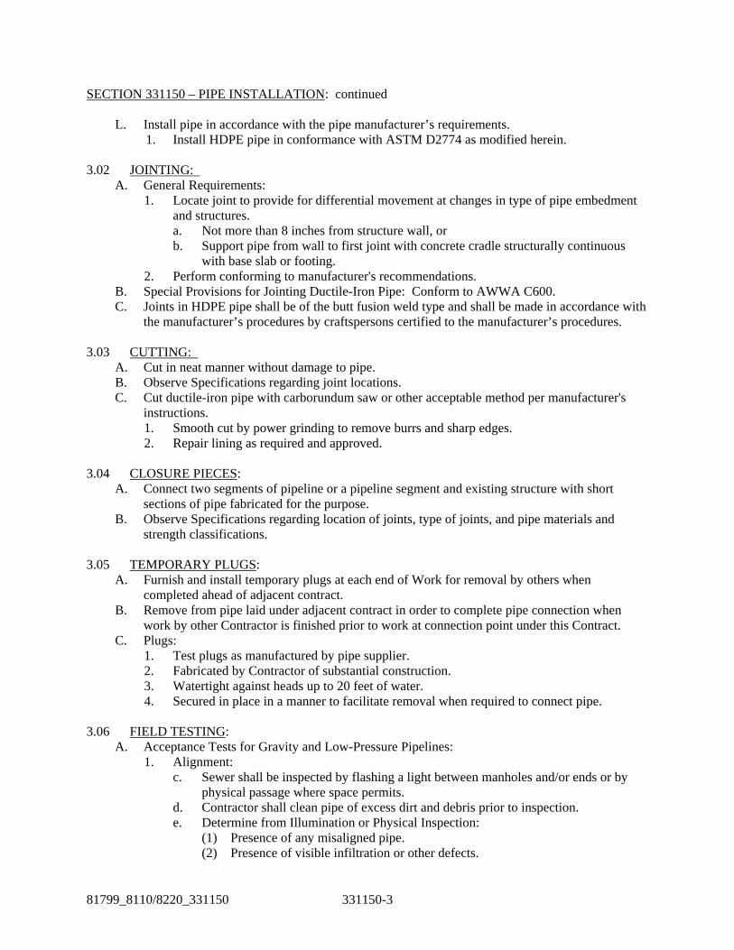
SECTION 331150 – PIPE INSTALLATION: continued
81799_8110/8220_331150 331150-3
L. Install pipe in accordance with the pipe manufacturer’s requirements. 1. Install HDPE pipe in conformance with ASTM D2774 as modified herein.
3.02 JOINTING:
A. General Requirements: 1. Locate joint to provide for differential movement at changes in type of pipe embedment
and structures. a. Not more than 8 inches from structure wall, or b. Support pipe from wall to first joint with concrete cradle structurally continuous
with base slab or footing. 2. Perform conforming to manufacturer's recommendations.
B. Special Provisions for Jointing Ductile-Iron Pipe: Conform to AWWA C600. C. Joints in HDPE pipe shall be of the butt fusion weld type and shall be made in accordance with
the manufacturer’s procedures by craftspersons certified to the manufacturer’s procedures.
3.03 CUTTING: A. Cut in neat manner without damage to pipe. B. Observe Specifications regarding joint locations. C. Cut ductile-iron pipe with carborundum saw or other acceptable method per manufacturer's
instructions. 1. Smooth cut by power grinding to remove burrs and sharp edges. 2. Repair lining as required and approved.
3.04 CLOSURE PIECES:
A. Connect two segments of pipeline or a pipeline segment and existing structure with short sections of pipe fabricated for the purpose.
B. Observe Specifications regarding location of joints, type of joints, and pipe materials and strength classifications.
3.05 TEMPORARY PLUGS: A. Furnish and install temporary plugs at each end of Work for removal by others when
completed ahead of adjacent contract. B. Remove from pipe laid under adjacent contract in order to complete pipe connection when
work by other Contractor is finished prior to work at connection point under this Contract. C. Plugs:
1. Test plugs as manufactured by pipe supplier. 2. Fabricated by Contractor of substantial construction. 3. Watertight against heads up to 20 feet of water. 4. Secured in place in a manner to facilitate removal when required to connect pipe.
3.06 FIELD TESTING:
A. Acceptance Tests for Gravity and Low-Pressure Pipelines: 1. Alignment:
c. Sewer shall be inspected by flashing a light between manholes and/or ends or by physical passage where space permits.
d. Contractor shall clean pipe of excess dirt and debris prior to inspection. e. Determine from Illumination or Physical Inspection:
(1) Presence of any misaligned pipe. (2) Presence of visible infiltration or other defects.

SECTION 331150 – PIPE INSTALLATION: continued
331150-4 81799_8110/8220_331150
f. Correct defects as required. B. Acceptance Tests for Pressure Pipelines:
1. Perform hydrostatic pressure and leakage tests. a. Conform to AWWA C600 procedures.
(1) As modified herein. (2) Shall apply to all pipe materials specified.
b. Perform after backfilling. 2. Test separately in segments between sectionalizing valves, between a sectionalizing valve
and a test plug, or between test plugs. a. Select test segments such that adjustable seated valves are isolated for individual
checking. b. Contractor shall furnish and install test plugs.
(1) Including all anchors, braces, and other devices to withstand hydrostatic pressure on plugs.
(2) Be responsible for any damage to public or private property caused by failure of plugs.
3. Limit fill rate of line to available venting capacity. Fill rate shall be regulated to limit velocity in lines when flowing full to not more than 0.05 to 1 fps.
4. Pressure and Leakage Test: a. Test pressure for potable, service, and raw watermains shall be 100 psi. b. Test pressure for fire protection mains shall be 150 psi. c. Test pressure for oil/water drains shall be 8 psi. d. Be at least 2-hour duration. Maintain pressure throughout test of test pressure. e. Leakage test shall be conducted concurrently with the pressure test. f. HDPE oil/water drains piping shall exhibit zero leakage. All other HDPE pipe shall
be acceptable when leakage does not exceed that determined by the following formula: In English units:
L = 0.0000075 SD(P)1/2, in which L = allowable leakage, in gallons per hour S = length of pipe tested, in feet D = nominal diameter of the pipe, in inches P = average actual leakage test pressure in psig
g. When testing against closed metal-seated valves, an additional leakage per closed valve of 0.0078 gal/hr/in of nominal valve size shall be allowed.
h. When hydrants are in the test section, the test shall be made against the main valve in the hydrant.
i. Repeat test as necessary. (1) After location of leaks and repair or replacement of defective joints, pipe,
fittings, valves or hydrants. All visible leaks are to be repaired regardless of the amount of leakage.
(2) Until satisfactory performance of test. j. Engineer will witness pressure and leakage test.
3.07 FILLING, FLUSHING, DISINFECTION, AND TESTING:
A. Sequence: 1. Clean. 2. Fill. 3. Flush.
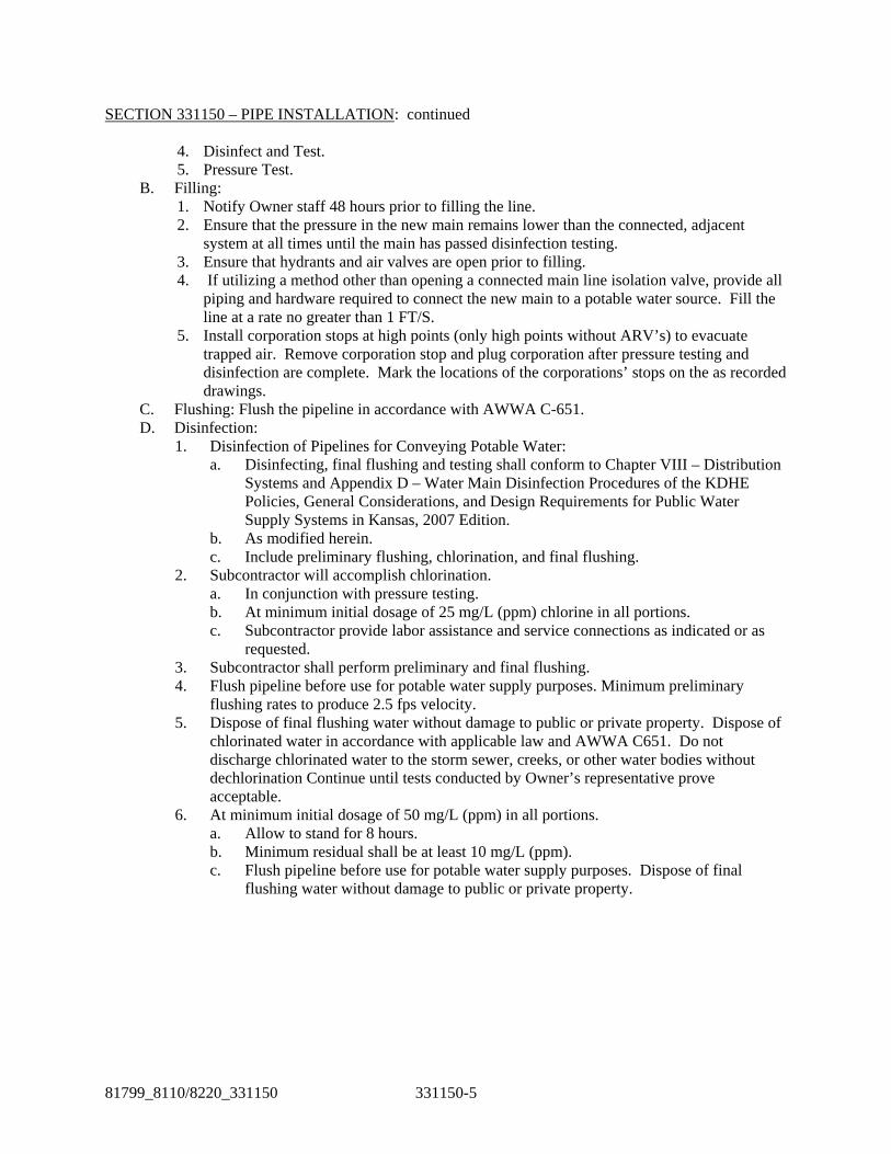
SECTION 331150 – PIPE INSTALLATION: continued
81799_8110/8220_331150 331150-5
4. Disinfect and Test. 5. Pressure Test.
B. Filling: 1. Notify Owner staff 48 hours prior to filling the line. 2. Ensure that the pressure in the new main remains lower than the connected, adjacent
system at all times until the main has passed disinfection testing. 3. Ensure that hydrants and air valves are open prior to filling. 4. If utilizing a method other than opening a connected main line isolation valve, provide all
piping and hardware required to connect the new main to a potable water source. Fill the line at a rate no greater than 1 FT/S.
5. Install corporation stops at high points (only high points without ARV’s) to evacuate trapped air. Remove corporation stop and plug corporation after pressure testing and disinfection are complete. Mark the locations of the corporations’ stops on the as recorded drawings.
C. Flushing: Flush the pipeline in accordance with AWWA C-651. D. Disinfection:
1. Disinfection of Pipelines for Conveying Potable Water: a. Disinfecting, final flushing and testing shall conform to Chapter VIII – Distribution
Systems and Appendix D – Water Main Disinfection Procedures of the KDHE Policies, General Considerations, and Design Requirements for Public Water Supply Systems in Kansas, 2007 Edition.
b. As modified herein. c. Include preliminary flushing, chlorination, and final flushing.
2. Subcontractor will accomplish chlorination. a. In conjunction with pressure testing. b. At minimum initial dosage of 25 mg/L (ppm) chlorine in all portions. c. Subcontractor provide labor assistance and service connections as indicated or as
requested. 3. Subcontractor shall perform preliminary and final flushing. 4. Flush pipeline before use for potable water supply purposes. Minimum preliminary
flushing rates to produce 2.5 fps velocity. 5. Dispose of final flushing water without damage to public or private property. Dispose of
chlorinated water in accordance with applicable law and AWWA C651. Do not discharge chlorinated water to the storm sewer, creeks, or other water bodies without dechlorination Continue until tests conducted by Owner’s representative prove acceptable.
6. At minimum initial dosage of 50 mg/L (ppm) in all portions. a. Allow to stand for 8 hours. b. Minimum residual shall be at least 10 mg/L (ppm). c. Flush pipeline before use for potable water supply purposes. Dispose of final
flushing water without damage to public or private property.

SECTION 331150 – PIPE INSTALLATION: continued
331150-6 81799_8110/8220_331150
7. Repeat disinfection procedure should initial treatment fail to yield satisfactory results. a. At no additional cost to Owner. b. Owner will provide water under terms stipulated for acceptance tests.
E. Testing: 1. General:
a. Pressure testing and leakage testing may be performed concurrently only if corporation stops or other means are provided to ensure that the water in the new main adjacent to the connected existing system is highly chlorinated.
b. Provide all necessary equipment, materials, manpower, and expertise. 2. Disinfection Testing:
a. Gather samples and conduct bacteriological testing to verify the sanitary condition of the installed pipeline, in accordance with AWWA C-651.
b. If the tested section fails the test, take corrective measures, and repeat testing. c. If any tested section fails two disinfection tests, take corrective measures, perform
disinfection again, and repeat testing. 3. Hydrostatic Testing:
a. Hydrostatic testing may be conducted prior to disinfection testing only with the approval of the Water Utilities Director and if backflow prevention methods are in place to protect the existing system from contamination from the new main.
b. Test in accordance with the AWWA standards and manuals of practice applicable to the pipe material(s) installed.
c. Test medium; drinking water. Air testing is not acceptable. d. Minimum test period: 2 hours. e. Test pressure: the lesser of 150 psi or the maximum pressure rating of all components
for the duration of the test. f. Measure test pressure relative to the lowest elevation of the test section. g. Maximum allowable pressure gauge increment: 5 psi. Use two gauges to verify
accuracy. h. Measure make-up water with a domestic water meter or other accurate measuring
device. i. If any visible leaks are observed or if the volume of make-up water required exceeds
the limits described by the AWWA standard applicable to the pipe material, the system will have failed the test. Correct the leakage and repeat the test until the system passes the test.
END OF SECTION 331150
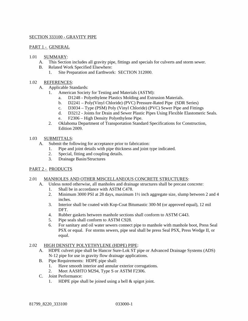
81799_8220_333100 033000-1
SECTION 333100 - GRAVITY PIPE
PART 1 - GENERAL
1.01 SUMMARY: A. This Section includes all gravity pipe, fittings and specials for culverts and storm sewer. B. Related Work Specified Elsewhere:
1. Site Preparation and Earthwork: SECTION 312000.
1.02 REFERENCES: A. Applicable Standards:
1. American Society for Testing and Materials (ASTM): a. D1248 - Polyethylene Plastics Molding and Extrusion Materials. b. D2241 – Poly(Vinyl Chloride) (PVC) Pressure-Rated Pipe (SDR Series) c. D3034 – Type (PSM) Poly (Vinyl Chloride) (PVC) Sewer Pipe and Fittings d. D3212 - Joints for Drain and Sewer Plastic Pipes Using Flexible Elastomeric Seals. e. F2306 – High Density Polyethylene Pipe.
2. Oklahoma Department of Transportation Standard Specifications for Construction, Edition 2009.
1.03 SUBMITTALS: A. Submit the following for acceptance prior to fabrication:
1. Pipe and joint details with pipe thickness and joint type indicated. 2. Special, fitting and coupling details. 3. Drainage Basin/Structures
PART 2 - PRODUCTS
2.01 MANHOLES AND OTHER MISCELLANEOUS CONCRETE STRUCTURES: A. Unless noted otherwise, all manholes and drainage structures shall be precast concrete:
1. Shall be in accordance with ASTM C478. 2. Minimum 3000 PSI at 28 days, maximum 1½ inch aggregate size, slump between 2 and 4
inches. 3. Interior shall be coated with Kop-Coat Bitumastic 300-M (or approved equal), 12 mil
DFT. 4. Rubber gaskets between manhole sections shall conform to ASTM C443. 5. Pipe seals shall conform to ASTM C928. 6. For sanitary and oil water sewers connect pipe to manhole with manhole boot, Press Seal
PSX or equal. For storms sewers, pipe seal shall be press Seal PSX, Press Wedge II, or equal.
2.02 HIGH DENSITY POLYETHYLENE (HDPE) PIPE: A. HDPE culvert pipe shall be Hancor Sure-Lok ST pipe or Advanced Drainage Systems (ADS)
N-12 pipe for use in gravity flow drainage applications. B. Pipe Requirements: HDPE pipe shall:
1. Have smooth interior and annular exterior corrugations. 2. Meet AASHTO M294, Type S or ASTM F2306.
C. Joint Performance: 1. HDPE pipe shall be joined using a bell & spigot joint.

SECTION 333100 – GRAVITY PIPE: continued
033000-2 81799-8220-333100
2. Gaskets, when applicable, shall be made of polyisoprene meeting the requirements of ASTM F477 with the addition that the gaskets shall not have any visible cracking when tested according to ASTM D1149 after 72 hour exposure in 50 PPHM ozone at 104° F (40° C).
3. Gaskets shall be installed by the pipe manufacturer and covered with a removable wrap to ensure the gasket is free from debris.
4. A joint lubricant supplied by the manufacturer shall be used on the gasket and bell during assembly.
5. Standard connections shall meet or exceed the soil-tight requirements of AASHTO M252, AASHTO M294, or ASTM F2306.
D. Material Properties: 1. Virgin material for pipe and fitting production shall be high density polyethylene. 2. Virgin pipe material shall be a slow crack resistant material evaluated using the notched
constant ligament-stress (NCLS) test according to the procedure described in AASHTO M294, Section 9.5. Average NCLS test specimens must exceed 24 hrs. with no test result less than 17 hrs.
2.03 END SECTIONS: A. Flared End Sections:
1. All culvert inlets and outlets shall have flared end sections. 2. Flared end sections shall be corrugated metal flared end sections. Flared end sections
shall be installed per manufacturer’s recommendations or as indicated on concrete drawings for attachment to culvert material utilized.
2.04 PVC PIPE: A. Sewer pipe shall be Poly Vinyl Chloride (PVC) pipe with Standard Dimension Ratio (SDR) 26
wall thickness conforming to ASTM F679, ASTM 2241, with gasketed push-on joints in conformance with ASTM D3212.
B. Materials and Manufacture: Conform to ASTM D3034 and ASTM F679 for pipes with smooth interior and exterior. 1. Joints:
a. Compression-type with the elastomeric ring gasket confined in the annular space between the bell end or socket and the spigot end of pipe.
b. Elastomeric gasket ring joints shall conform to the requirements of ASTM D3212 or ASTM F477.
c. Plain end of pipe shall be marked with a reference line to facilitate assembly inspection
2. Connections: Furnish any special flexible couplings required for manhole tie-ins or pipes or dissimilar materials
2.05 HDPE OIL/WATER SEWER PIPE: A. Pipe materials, fittings, and connections shall be per Piping Material Specifications (PM Specs)
00PDH01 per SECTION 485610 Appendix 1 – Piping Material Specifications. B. Inspection and Testing:
1. Primarily by manufacturer's testing laboratory and quality control personnel. 2. Perform to avoid, insofar as possible, delivery of defective pipe. 3. May be witnessed by Engineer or approved independent testing laboratory.
a. Independent testing laboratory, when used, shall be retained by Engineer at no expense to Contractor.

SECTION 333100 – GRAVITY PIPE: continued
81799-8220-333100 033000-3
b. Contractor and manufacturer shall cooperate with Engineer's inspection and test personnel. Permit unrestricted access, furnish reasonable space and facilities, and provide 5 working days advance notice of test schedule.
4. Contractor shall provide 3 copies each of certified test reports to Engineer. a. Include stiffness and deflection, dimension, and hydrostatic joint tests per ASTM
D3034, D3212, F679, F794, and F949. b. Furnish prior to delivery.
C. Handling and Delivery: 1. Use equipment and methods adequate to preserve quality of pipe and to protect joint
elements.
PART 3 - EXECUTION
3.01 PIPE EMBEDMENT: A. Granular Pipe Embedment: Gradation shall conform to the following for culverts:
1. Material: Per SECTION 331100 - Trenching and Backfilling for Utilities 2. Execution: Per SECTION 331100 – Trenching and Backfilling for Utilities.
3.02 TRENCH BACKFILL: 1. Per SECTION 331100 – Trenching and Backfilling for Utilities.
3.03 INSTALLATION: A. Insofar as possible, commence laying at downstream end of line and install pipe with spigot or
tongue ends in direction of flow. Obtain Engineer approval for deviations therefrom.
3.01 FIELD TESTING: B. Field testing shall be per Section 331150 – Pipe Installation
END OF SECTION 333100