cisco connected grid 4-port serial grwic installation and ... · – eia-232 – eia-449 –...
TRANSCRIPT

Cisco Connected Grid 4-Port Serial GRWIC Installation and Configuration Guide
First Published: May 6, 2014Last Updated: June 30, 2014OL-32086-03
This document describes how to install and configure the Cisco Connected Grid 4-port serial Grid Router WAN interface Card (GRWIC). This module enables the Cisco 2010 Connected Grid Router (CGR 2010) to connect to a Wide Area Network (WAN).
This document includes the following sections:
• Information About the 4-Port Serial GRWIC, page 1
• Hardware Overview, page 3
• Installing and Removing the 4-Port Serial GRWIC, page 7
• Connecting the 4-Port Serial GRWIC to the Network, page 9
• Software Configuration, page 11
• Related Documents, page 18
Information About the 4-Port Serial GRWICThe single-slot 4-port serial GRWIC (product ID GRWIC-4T) provides serial connectivity to the CGR 2010, a ruggedized power utility substation router. The GRWIC (see Figure 1) has 4 serial ports that support V.10/V.11/V.28/V.35 signaling types and asynchronous and synchronous protocols.
Utilities commonly have legacy equipment that communicates over relatively slow serial links. The 4-port serial GRWIC helps customers to enable applications such as legacy protocol transport, console server, and dial access server. Combining a high-density serial GRWIC with the CGR 2010 enables energy networks to collect and transport data from a Supervisory and Data Acquisition (SCADA) system over an IP network.
Cisco Systems, Inc.www.cisco.com
Information About the 4-Port Serial GRWIC
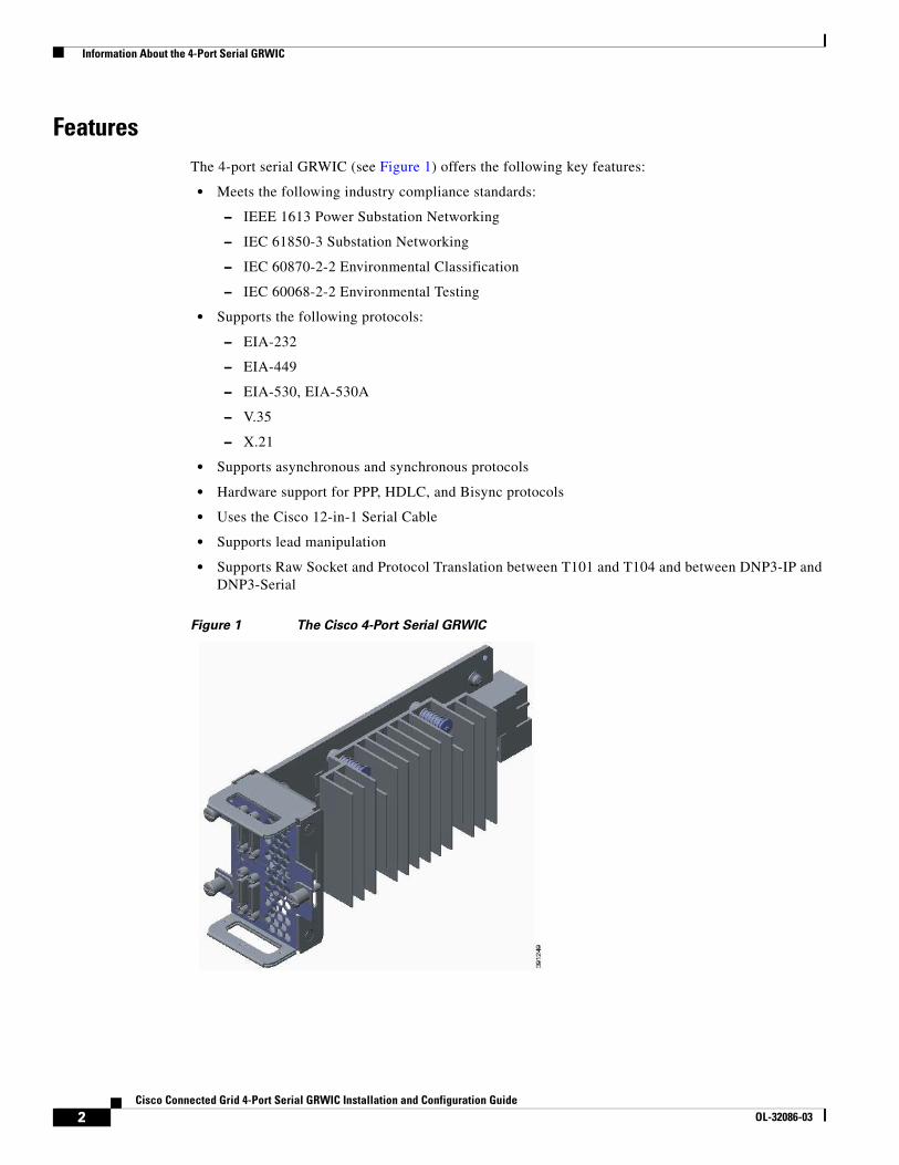
FeaturesThe 4-port serial GRWIC (see Figure 1) offers the following key features:
• Meets the following industry compliance standards:
– IEEE 1613 Power Substation Networking
– IEC 61850-3 Substation Networking
– IEC 60870-2-2 Environmental Classification
– IEC 60068-2-2 Environmental Testing
• Supports the following protocols:
– EIA-232
– EIA-449
– EIA-530, EIA-530A
– V.35
– X.21
• Supports asynchronous and synchronous protocols
• Hardware support for PPP, HDLC, and Bisync protocols
• Uses the Cisco 12-in-1 Serial Cable
• Supports lead manipulation
• Supports Raw Socket and Protocol Translation between T101 and T104 and between DNP3-IP and DNP3-Serial
Figure 1 The Cisco 4-Port Serial GRWIC
2Cisco Connected Grid 4-Port Serial GRWIC Installation and Configuration Guide
OL-32086-03

Hardware Overview
Timing Signals
The 4-port serial GRWIC interfaces support both the data terminal equipment (DTE) and data communication equipment (DCE) mode, depending on the mode of the compact serial cable attached to the port. To use a port as a DTE interface, you only need to connect a DTE compact serial cable to the port. When the system detects the DTE mode cable, it automatically uses the external timing signal. To use a port in DCE mode, you must connect a DCE compact serial cable and set the clock speed with the clock rate configuration command. See Configuring Basic Options, page 12 to set the clock speed.
Encapsulation Protocols
Encapsulation protocols connect the Layer 2 (link layer) protocols with the Layer 3 (network layer) protocols. When traffic crosses a WAN link, the connection needs a layer 2 protocol to encapsulate traffic. The 4-port serial GRWIC interface supports the High-Level Data Link Control (HDLC), Point-to-point (PPP), and Frame Relay encapsulation protocols. The HDLC protocol, a proprietary protocol, decodes proprietary framing used by the routers on the PPP links. The standard PPP protocol supports PPP links analyzed by HDLC and can also be utilized for Frame Relay. The standard Frame Relay encapsulation protocol is a versatile and common encapsulation protocol used with Frame Relay. See Configuring Basic Options, page 12 to set the encapsulation method.
Lead Manipulation
The lead manipulation feature allows a user to ignore input signals on the physical interface, view the state of the input signals, and monitor the transitions of the input signals. By default, Cisco IOS software requires assertion of some of the input leads on the physical interface. With lead manipulation, the user can configure the serial interface to ignore input signals. See Ignoring Input Signals, page 13.
Hardware OverviewThis section includes the following topics:
• Specifications, page 3
• Ports and LEDs, page 5
• Cables, page 6
SpecificationsThis section includes the following topics:
• Hardware Specifications, page 4
• Environmental Specifications, page 4
• Power Specifications, page 4
3Cisco Connected Grid 4-Port Serial GRWIC Installation and Configuration Guide
OL-32086-03

Hardware Overview
Hardware Specifications
Table 1 summarizes the hardware specifications of the 4-port serial GRWIC supported on the CGR 2010.
Environmental Specifications
Table 2 lists the environmental specifications for the 4-port serial GRWIC.
Power Specifications
Typical power consumption of the 4-port serial GRWIC is approximately 4.8W.
Table 1 Hardware Specifications for the 4-Port Serial GRWIC
Item Description
Dimensions (H x W x D) 3 x 2 x 6.5 in. (7.62 x 5.08 x 16.51 cm)
Slot Restrictions None
Number of ports 4
Connector Cisco 12-in-1 connector
Synchronous maximum speed (per port) 8 Mbps
Asynchronous maximum speed (per port) 230.4 kbps
Table 2 Environmental Specification for the 4-Port Serial GRWIC
Condition Requirement
Operating Conditions
Temperature -40ºF to 140ºF (-40 to +60ºC) continuous operating temperature range
-40ºF to 185ºF (-40 to +85ºC) type test for 100 hours at 85ºC
Relative humidity 5 to 95% non-condensing
Altitude 10,000 ft (3,048 m) Maximum operating temperature is de-rated with increasing altitude per IEEE 1613a-2008
Shock/vibration 30G @11 ms
Non-Operating Conditions
Temperature -40ºF to 185ºF (-40ºC to 85ºC)
Relative humidity 5 to 95% non-condensing
Altitude 16,000 ft (4,876 m) Maximum operating temperature is de-rated with increasing altitude per IEEE 1613a-2008
Shock/vibration 40-50G (3.26 m/s minimum)
Free fall drop 4 in. (100 mm) per ENG-339611
Seismic/earthquake NEBS GR-63 (5.4.1)
4Cisco Connected Grid 4-Port Serial GRWIC Installation and Configuration Guide
OL-32086-03

Hardware Overview
Ports and LEDsFigure 2 shows the front panel of the 4-port serial GRWIC.
Figure 2 4-Port Serial GRWIC Front View
Figure 2 shows that the 4-port serial GRWIC has one LED, labeled CONN, for ports 0-3. The LED lights when the serial port is connected. When the port is in DTE mode, the CONN LED indicates that Data Send Ready (DSR), Data Carrier Detect (DCD), and Clear To Send (CTS) have been detected. When the port is in DCE mode, Data Terminal Ready (DTR) and Ready To Send (RTS) have been detected. Table 3 describes the functions of the LEDs.
2
1 1
3912
50
1 Serial port (4) 2 Bi-color LED for ports 0-3
Table 3 Serial GRWIC LED
LED Description
Solid Green The card is active (initialized without error).
Blinking Green At least one port is passing traffic.
Yellow At least one port is in loopback mode.
Blinking Yellow At least one port has failed.
Off The card is is not active or has failed to initialize.
5Cisco Connected Grid 4-Port Serial GRWIC Installation and Configuration Guide
OL-32086-03

Hardware Overview
CablesThe interface cables for the 4-port serial GRWIC are rated for -4 degrees F (-20 degrees C) to 167 degrees F (75 degrees C). At -40C (the low end of the operating temperature range of the CGR 2010), the smart serial cable will perform optimally provided that the following conditions are met:
• The cable is not bent or flexed more than 5 times the nominal diameter.
• The cable is not strained under its own weight and is properly secured to the cable management system.
• The cable is not pinched and the cable jacket is not cracked from high impact or other damage.
• The cables connect equipment within a controlled environment such as an equipment room or vented cabinet and are not used outdoors in the field.
For information about connecting the cables, see “Connecting the 4-Port Serial GRWIC to the Network” section on page 9.
Table 4 lists the serial cables for the supported serial connection types.
Table 4 Interface Cables for 12-in-1 Connector
Interface Type and description Cisco Product Number Protocol Type
V.35 DTE, 10 ft (3 m), Plug M34 CAB-SS-V35MT V.35 DTE SYNC
V.35 DCE, 10 ft (3 m), Socket M34
CAB-SS-V35FC V.35 DCE SYNC
EIA/TIA-232 DTE, 10 ft (3 m), Plug DB-25
CAB-SS-232MT RS232 DTE, Sync/Async, Max BAUD rate=230.4 kbps
EIA/TIA-232 DCE, 10 ft (3 m), Socket DB-25
CAB-SS-232FC RS232 DCE, Sync/Async, Max BAUD rate=230.4 kbps
EIA/TIA-449 DTE, 10 ft (3 m), Plug DB-37
CAB-SS-449MT RS-449 DTE SYNC
EIA/TIA-449 DCE, 10 ft (3 m), Socket, DB-37
CAB-SS-449FC RS-449 DCE SYNC
X.21 DTE, 10 ft (3 m), Plug, DB-15
CAB-SS-X21MT X.21 DTE SYNC
X.21 DCE, 10 ft (3 m), Socket, DB-15
CAB-SS-X21FC X.21 DCE SYNC
EIA/TIA-530 DTE, 10 ft (3 m), Plug, DB-25
CAB-SS-530MT RS-530 DTE SYNC
EIA/TIA-530 DTE, 10 ft (3 m), Plug, DB-25
CAB-SS-530FC RS-530 DTE SYNC
EIA/TIA-530A DTE, 10 ft (3 m), Plug, DB-25
CAB-SS-530AMT RS-530A DTE SYNC
EIA/TIA-530A DCE, 10 ft (3 m), Plug, DB-25
CAB-SS-530AFC RS-530A DCE SYNC
6Cisco Connected Grid 4-Port Serial GRWIC Installation and Configuration Guide
OL-32086-03

Installing and Removing the 4-Port Serial GRWIC
Installing and Removing the 4-Port Serial GRWICThis section describes how to install the 4-port serial GRWIC in the CGR 2010 and includes the following topics:
• Safety Warnings, page 7
• Installing a 4-Port Serial GRWIC, page 7
• Removing a 4-Port Serial GRWIC, page 9
Safety WarningsThis section includes the basic installation warning statements for the 4-port serial GRWIC. For regulatory compliance and safety information for the CGR 2010, refer to the Connected Grid Router 2000 Series Regulatory Compliance and Safety Information document.
http://www.cisco.com/en/US/docs/routers/access/2000/CGR2010/hardware/rcsi/rcsiCGR2000series.html
Warning Only trained and qualified personnel should be allowed to install, replace, or service this equipment. Statement 1030
Warning Do not work on the system or connect or disconnect cables during periods of lightning activity. Statement 1001
Warning Read the installation instructions before connecting the system to the power source. Statement 1004
Warning Hazardous network voltages are present in WAN ports regardless of whether power to the unit is OFF or ON. To avoid electric shock, use caution when working near WAN ports. When detaching cables, detach the end away from the unit first. Statement 1026
Installing a 4-Port Serial GRWICYou can install the 4-port serial GRWIC into one of four slots on the cable side of the router.
Follow these steps to install a 4-port serial GRWIC in a CGR 2010:
Step 1 Stand the GRWIC on end to install into the router slot. (See Figure 3.)
7Cisco Connected Grid 4-Port Serial GRWIC Installation and Configuration Guide
OL-32086-03

Installing and Removing the 4-Port Serial GRWIC
Figure 3 GRWIC Positioning to Install into the GCR 2010 Router
Step 2 Slide the GRWIC into the router slot. (See Figure 4.)
Figure 4 Proper Installation of a GRWIC
Step 3 Tighten the three captive screws on the front of the interface card.
8Cisco Connected Grid 4-Port Serial GRWIC Installation and Configuration Guide
OL-32086-03

Connecting the 4-Port Serial GRWIC to the Network
Removing a 4-Port Serial GRWICTo remove a 4-port serial GRWIC from a CGR 2010, perform these steps:
Step 1 Using a screwdriver, loosen the three captive screws on the 4-port serial GRWIC.
Step 2 Gently pull the module out of the slot.
Connecting the 4-Port Serial GRWIC to the NetworkBefore connecting a GRWIC to the network, ensure that the GRWIC is installed in the router and you have the proper cables for connecting the GRWIC to the network. See Table 4 on page 6 for the cable descriptions.
Note The interface cables are designed to connect equipment within a controlled environment such as an equipment room or vented cabinet and are not designed or intended to be used outdoors in the field.
To connect the 4-port serial GRWIC to the network, follow these steps:
Step 1 Connect the serial cable to the connector on the GRWIC faceplate. (See Figure 5.)
Step 2 Secure the thumb screws on the cable to the GRWIC faceplate. (See Figure 5.)
9Cisco Connected Grid 4-Port Serial GRWIC Installation and Configuration Guide
OL-32086-03

Connecting the 4-Port Serial GRWIC to the Network
Figure 5 Connecting the Serial GRWIC Interface
Step 3 Route the serial cable using a cable management system, such as a vertical cable manager, to ensure that the weight of the cable is supported (see Figure 6). Allow a short length (3 to 6 inches) of the cable to exit perpendicular to the connector.
1 Serial interface 2 One of the serial cable types listed in Table 4, “Interface Cables for 12-in-1 Connector” (female serial cable shown as an example)
3 Matching serial cable for type listed in Table 4, “Interface Cables for 12-in-1 Connector” (male serial cable shown as an example)
CONNS-0 S-1
S-2 S-3
GRWIC-4T
3912
52
2
3
1
10Cisco Connected Grid 4-Port Serial GRWIC Installation and Configuration Guide
OL-32086-03

Software Configuration
Figure 6 Routing the Serial Cable
Step 4 Connect the female end of the serial cable to the male end of the other serial cable for back-to-back connectivity. (See Figure 5.)
Step 5 Connect the other end of the cable to the DTE or DCE.
Software ConfigurationThis section includes the following topics:
• Restrictions for the 4-Port Serial GRWIC, page 11
• Configuring the 4-Port Serial GRWIC, page 12
• Verifying Configuration, page 14
• Configuration Example, page 16
Restrictions for the 4-Port Serial GRWIC• Network clocking synchronization is not supported. Note that the serial protocol is terminating at
the GRWIC-4T and the raw packet is forwarded across the network. Therefore, end-to-end clocking is not required for reliable data transport.
• The GRWIC-4T does not support Nx64k/56kbps baud rates.
1 Vertical cable manager 2 Serial cable
3914
42
1
2
11Cisco Connected Grid 4-Port Serial GRWIC Installation and Configuration Guide
OL-32086-03
Software Configuration
Configuring the 4-Port Serial GRWIC This section includes the following topics:
• Configuring Basic Options, page 12
• Ignoring Input Signals, page 13
• Configuring Loopback Test, page 14
• Verifying Configuration, page 14
• Configuration Example, page 16
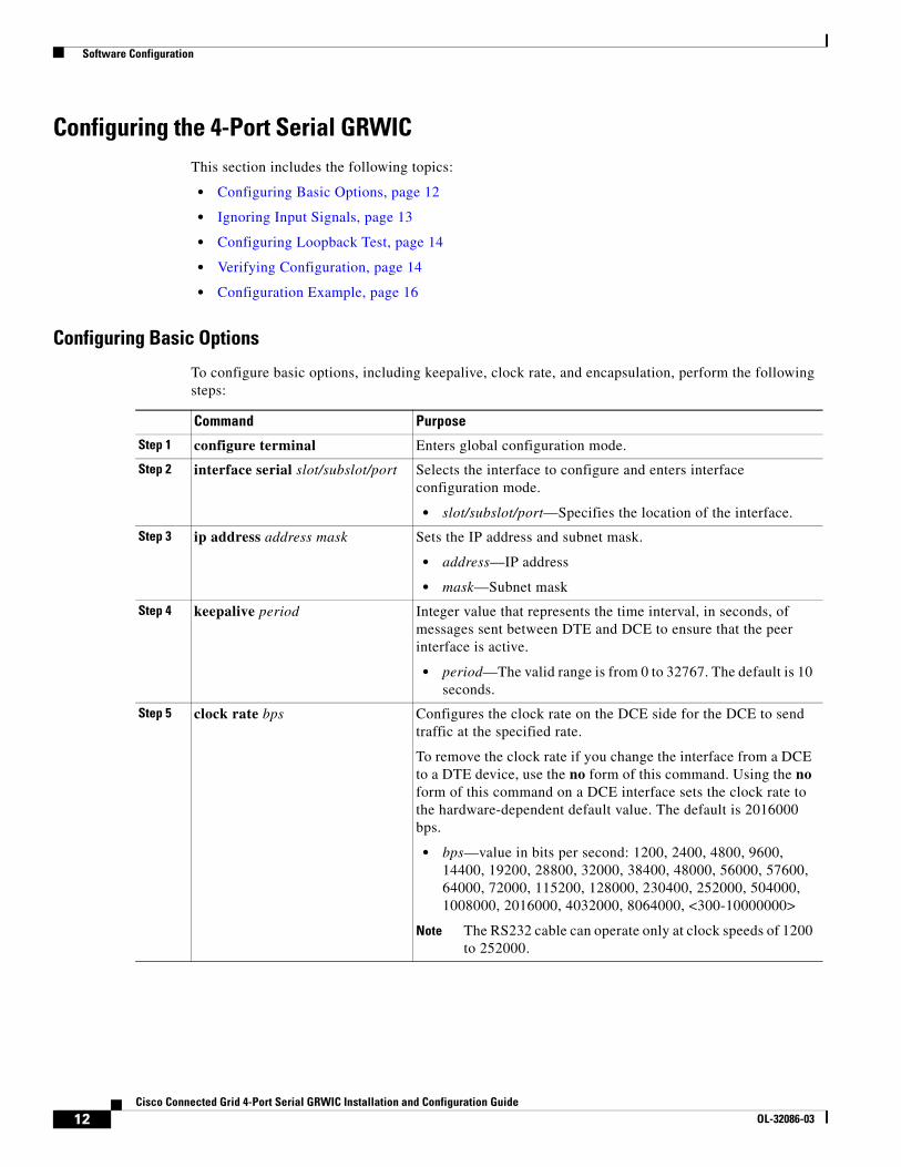
Configuring Basic Options
To configure basic options, including keepalive, clock rate, and encapsulation, perform the following steps:
Command Purpose
Step 1 configure terminal Enters global configuration mode.
Step 2 interface serial slot/subslot/port Selects the interface to configure and enters interface configuration mode.
• slot/subslot/port—Specifies the location of the interface.
Step 3 ip address address mask Sets the IP address and subnet mask.
• address—IP address
• mask—Subnet mask
Step 4 keepalive period Integer value that represents the time interval, in seconds, of messages sent between DTE and DCE to ensure that the peer interface is active.
• period—The valid range is from 0 to 32767. The default is 10 seconds.
Step 5 clock rate bps Configures the clock rate on the DCE side for the DCE to send traffic at the specified rate.
To remove the clock rate if you change the interface from a DCE to a DTE device, use the no form of this command. Using the no form of this command on a DCE interface sets the clock rate to the hardware-dependent default value. The default is 2016000 bps.
• bps—value in bits per second: 1200, 2400, 4800, 9600, 14400, 19200, 28800, 32000, 38400, 48000, 56000, 57600, 64000, 72000, 115200, 128000, 230400, 252000, 504000, 1008000, 2016000, 4032000, 8064000, <300-10000000>
Note The RS232 cable can operate only at clock speeds of 1200 to 252000.
12Cisco Connected Grid 4-Port Serial GRWIC Installation and Configuration Guide
OL-32086-03

Software Configuration
Note See Configuring Raw Socket Protocol on the CGR 2010 Router for more information about configuring Raw Socket.
Ignoring Input Signals
You can configure an interface operating in DCE mode to ignore incoming Data Terminal Ready (DTR) or Ready to Send (RTS) signals. When you configure the ignore [dtr | rts] command, a signal is automatically seen as asserted.
To configure the interface to ignore DTR and RTS signals, perform the following steps:
Step 6 physical-layer {sync | async} Specifies the mode of the serial interface as either synchronous or asynchronous.
• sync—synchronous mode (default).
• async—asynchronous mode.
Step 7 encapsulation {hdlc | ppp | frame-relay | raw-tcp | raw-udp}
Sets the encapsulation type on the interface.
• hdlc—High-Level Data Link Control (HDLC) protocol for serial interface (default).
• ppp—Point-to-Point Protocol (PPP).
• frame-relay—Frame Relay.
• raw-tcp—Raw Socket TCP for the asynchronous serial port.
• raw-udp—Raw Socket UDP for the asynchronous serial port.
Note For raw-tcp or raw-udp, the mode of the serial interface must be set to async.
Command Purpose
Command Purpose
Step 1 configure terminal Enters global configuration mode.
Step 2 interface serial slot/subslot/port Selects the interface to configure and enters interface configuration mode.
• slot/subslot/port—Specifies the location of the interface.
Step 3 ignore [dtr | rts] Configures the DCE to ignore the specified signal.
• dtr—DCE ignores DTR signals.
• rts—DCE ignores RTS signals.
13Cisco Connected Grid 4-Port Serial GRWIC Installation and Configuration Guide
OL-32086-03
Software Configuration
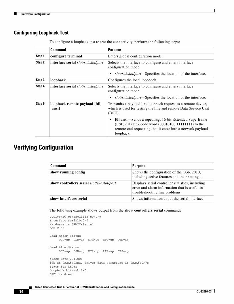
Configuring Loopback Test
To configure a loopback test to test the connectivity, perform the following steps:
Verifying Configuration
The following example shows output from the show controllers serial command:
UUT1#show controllers s0/0/0Interface Serial0/0/0Hardware is GRWIC-SerialDCE V.35
Lead Modem Status DCD=up DSR=up DTR=up RTS=up CTS=up
Lead Line Status DCD=up DSR=up DTR=up RTS=up CTS=up
clock rate 2016000idb at 0x2A5E02BC, driver data structure at 0x2A5E0F78Stats for LED(s):Loopback bitmask 0x0LED1 is Green
Command Purpose
Step 1 configure terminal Enters global configuration mode.
Step 2 interface serial slot/subslot/port Selects the interface to configure and enters interface configuration mode.
• slot/subslot/port—Specifies the location of the interface.
Step 3 loopback Configures the local loopback.
Step 4 interface serial slot/subslot/port Selects the interface to configure and enters interface configuration mode.
• slot/subslot/port—Specifies the location of the interface.
Step 5 loopback remote payload [fdl] [ansi]
Transmits a payload line loopback request to a remote device, which is used for testing the line and remote Data Service Unit (DSU).
• fdl ansi—Sends a repeating, 16-bit Extended Superframe (ESF) data link code word (00010100 11111111) to the remote end requesting that it enter into a network payload loopback.
Command Purpose
show running config Shows the configuration of the CGR 2010, including active features and their settings.
show controllers serial slot/subslot/port Displays serial controller statistics, including error and alarm information that is useful in troubleshooting line problems.
show interfaces serial Shows information about the serial interface.
14Cisco Connected Grid 4-Port Serial GRWIC Installation and Configuration Guide
OL-32086-03

Software Configuration
GRWIC Register Base: 0x10000000------------------GRWIC Common Registers:---------------------id(0x00): 0x00000001 rev(0x01): 0x00000002 status(0x02): 0x00000000tx crc(0x01): 0x00000000 ctrl(0x06): 0x00008081
GRWIC Serial Common Registers:----------------------------hwic_serial_rev(0x1000): 0x08232013 hwic_serial_ctrl(0x1004): 0x00008009intr1_enable(0x1020): 0x0000002A intr2_enable(0x1022): 0x0000000F
GRWIC Serial SCC Registers:----------------------------ch_mode_cfg: 0x08019031 ch_flag_cfg: 0x0000007E ch_floctrl_cfg: 0x00000000ch_int_enable: 0x000009FF ch_cmd_stat: 0x00000050 ch_tx_empty_stat: 0x00000001
GRWIC Serial DMA Registers:-------------------------Rx ring_start_ptr: 0x0E944C00 Rx ring_mask_index: 0x01F80060internal_desc_stat: 0x0400060C internal_buff_addr: 0x0E965AC8internal_context: 0x00000013 internal_fifo_data: 0x0E969567Tx ring_start_ptr: 0x0E946080 Tx ring_mask_index: 0x03F80060internal_desc_stat: 0x00000000 internal_buff_addr: 0x0E94C4F1internal_context: 0x00000441 internal_fifo_data: 0x31555554
GRWIC Serial Interface Registers:-------------------------------intf_ctrl: 0x0019 modem_ctrl: 0x011D flow_ctrl: 0x7430 brg dvdr:0x0004
GRWIC TDM/FREQ Counter Registers:--------------------------------tdm_control: 0x0000 tdm_a_8k_divider: 0x0000 tdm_b_8k_divider: 0x0000freq_count_port_sel: 0x000B freq_count: 0x14A4B6
0 input aborts on receiving flag sequence0 throttles, 0 enables0 overruns0 transmitter underruns0 transmitter CTS losts0 aborted short frames0 CRC short frames count0 rxintr, 0 txintr, 0 rxerr, 0 txerr0 rx_bogus_pkts, rx_bogus_flag FALSE 0 tx_abort, 0 tx_reset
tx_limited = 0(128) tx_count = 0 idb at 0x2A5E02BC, driver data structure at 0x2A5E0F78Receive Ring rxr head (12)(0x0E944C60), rxr tail (0)(0x0E944C00) rmd(E944C00): desc_stat_len 8400060C desc_buff_addr E964DC8 rmd(E944C08): desc_stat_len 8400060C desc_buff_addr E9640C8 rmd(E944C10): desc_stat_len 8400060C desc_buff_addr E967B48
.
.
.Transmit Ring txr head (12)(0x0E9460E0), txr tail (12)(0x0E9460E0) tmd(E946080): desc_stat_len 05C00000 desc_buff_addr DDA00D4 tmd(E946088): desc_stat_len 05C00000 desc_buff_addr DDA0254 tmd(E946090): desc_stat_len 05C00000 desc_buff_addr DDA09D4
15Cisco Connected Grid 4-Port Serial GRWIC Installation and Configuration Guide
OL-32086-03

Software Configuration
.
.
.buffer size 1524
UUT1#
This example shows the output from the show interfaces command for a serial interface:
UUT1#show int s0/0/0Serial0/0/0 is up, line protocol is up
Hardware is GRWIC-Serial MTU 1500 bytes, BW 2048 Kbit/sec, DLY 20000 usec,
reliability 255/255, txload 1/255, rxload 1/255 Encapsulation PPP, LCP Open, loopback not set Keepalive set (10 sec) DTR is pulsed for 1 seconds on reset Time to interface disconnect: idle 00:59:42 Interface is bound to Di1 (Encapsulation PPP) CRC checking enabled Last input 00:00:07, output 00:00:07, output hang never Last clearing of "show interface" counters 04:07:36Input queue: 0/75/0/0 (size/max/drops/flushes); Total output drops: 0 Queueing strategy: fifo Output queue: 0/40 (size/max) 5 minute input rate 0 bits/sec, 0 packets/sec 5 minute output rate 0 bits/sec, 0 packets/sec
1852 packets input, 47678 bytes, 0 no buffer Received 0 broadcasts (0 IP multicasts) 0 runts, 0 giants, 0 throttles 0 input errors, 0 CRC, 0 frame, 0 overrun, 0 ignored, 0 abort
2101 packets output, 50723 bytes, 0 underruns 0 output errors, 0 collisions, 396 interface resets 73 unknown protocol drops 0 output buffer failures, 0 output buffers swapped out 596 carrier transitions DCD=up DSR=up DTR=up RTS=up CTS=up
UUT1#
Configuration ExampleThis section includes the following topics:
• Frame Relay, page 16
• Dial-on-Demand (DDR), page 17
Frame Relay
The following example shows a Frame Relay configuration between routers UUT-1 and UUT-2:
UUT-1:
interface Serial0/0/3 no ip address encapsulation frame-relay no keepalive!interface Serial0/0/3.1 point-to-point ip address 172.16.120.105 255.255.255.0
16Cisco Connected Grid 4-Port Serial GRWIC Installation and Configuration Guide
OL-32086-03

Software Configuration
frame-relay interface-dlci 101!
UUT-2:
interface Serial0/0/3 no ip address encapsulation frame-relay no keepalive clock rate 64000!interface Serial0/0/3.1 point-to-point ip address 172.16.120.120 255.255.255.0 frame-relay interface-dlci 101!
Verify ping works to the other end, and verify the output of the following show commands:
UUT-1# show frame mapSerial0/0/3.1 (up): point-to-point dlci, dlci 101(0x65,0x1850), broadcastUUT-1#UUT-1#UUT-1# show frame pvc
PVC Statistics for interface Serial0/0/3 (Frame Relay DTE)
Active Inactive Deleted Static Local 1 0 0 0 Switched 0 0 0 0 Unused 0 0 0 0
DLCI = 101, DLCI USAGE = LOCAL, PVC STATUS = STATIC, INTERFACE = Serial0/0/3.1
input pkts 7 output pkts 9 in bytes 2081 out bytes 2720 dropped pkts 0 in pkts dropped 0 out pkts dropped 0 out bytes dropped 0 in FECN pkts 0 in BECN pkts 0 out FECN pkts 0 out BECN pkts 0 in DE pkts 0 out DE pkts 0 out bcast pkts 9 out bcast bytes 2720 5 minute input rate 0 bits/sec, 0 packets/sec 5 minute output rate 0 bits/sec, 0 packets/sec pvc create time 00:07:36, last time pvc status changed 00:07:36UUT-1#
Dial-on-Demand (DDR)
The following example shows the configuration for DDR:
interface Dialer1 ip address 1.1.1.1 255.255.255.0 encapsulation PPP dialer remote-name R2 dialer string 555430 dialer caller 555430 dialer pool 10 dialer group 1 dialer-list dialer group protocol <ip> permitinterface s0/0/2 dialer in-band encapsulation ppp dialer pool-member 10
17Cisco Connected Grid 4-Port Serial GRWIC Installation and Configuration Guide
OL-32086-03

Feature History
Feature HistoryCisco Feature Navigator provides information about platform support, software image support, including software image and their supported software release, feature set, or platform.
You can access Cisco Feature Navigator by going to http://www.cisco.com/go/cfn. An account on Cisco.com is not required.
Table 5 lists the release history for this feature.
Note Table 5 lists only the software release that introduced support for a given feature in a given software release train. Unless noted otherwise, subsequent releases of that software release train also support that feature.
Related Documents• Cisco Connected Grid Routers 2010 Hardware Installation Guide
• Configuring Raw Socket Protocol on the CGR 2010 Router
Obtaining Documentation and Submitting a Service RequestFor information on obtaining documentation, using the Cisco Bug Search Tool (BST), submitting a service request, and gathering additional information, see What’s New in Cisco Product Documentation at: http://www.cisco.com/c/en/us/td/docs/general/whatsnew/whatsnew.html.
Subscribe to What’s New in Cisco Product Documentation, which lists all new and revised Cisco technical documentation, as an RSS feed and deliver content directly to your desktop using a reader application. The RSS feeds are a free service.
This document is to be used in conjunction with the documents listed in the “Related Documents” section.
Cisco and the Cisco logo are trademarks or registered trademarks of Cisco and/or its affiliates in the U.S. and other countries. To view a list of Cisco trademarks, go to this URL: www.cisco.com/go/trademarks. Third-party trademarks mentioned are the property of their respective owners. The use of the word partner does not imply a partnership relationship between Cisco and any other company. (1110R)
No combinations are authorized or intended under this document.
Any Internet Protocol (IP) addresses and phone numbers used in this document are not intended to be actual addresses and phone numbers. Any examples, command display output, network topology diagrams, and other figures included in the document are shown for illustrative purposes only. Any use of actual IP addresses or phone numbers in illustrative content is unintentional and coincidental.
© 2014 Cisco Systems, Inc. All rights reserved.
Table 5 Feature Information for 4-Port Serial GRWIC
Feature Name Release Feature Information
4-port serial GRWIC module for the Connected Grid Router 2010
15.4.(1)CG1 Provides the CGR 2010 with WAN connectivity options for serial protocols and interfaces.
18Cisco Connected Grid 4-Port Serial GRWIC Installation and Configuration Guide
OL-32086-03