chopper op manual side discharge complete chopper operator manual.pdf · chopper on a daily basis....
TRANSCRIPT
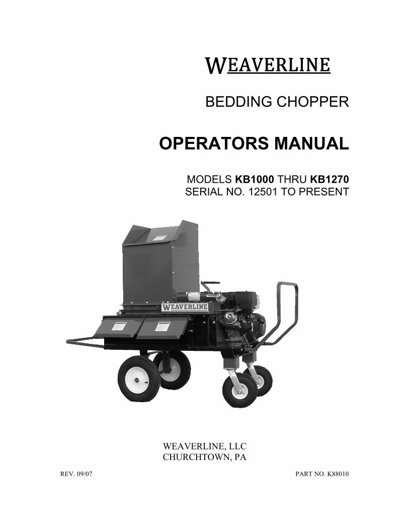
WWWWEAVERLINEEAVERLINEEAVERLINEEAVERLINE
BEDDING CHOPPER
OPERATORS MANUAL
MODELS KB1000 THRU KB1270 SERIAL NO. 12501 TO PRESENT
WEAVERLINE, LLC
CHURCHTOWN, PA
REV. 09/07 PART NO. K88010

INTRODUCTION
THANK YOU…
For choosing a Weaverline Bedding Chopper. A productmanufactured in the U.S.A by Weaverline, LLC ofChurchtown, Pennsylvania, founded in 1965. When usedand maintained properly your investment will provide yearsof dependable performance.
PURPOSE
The purpose of this manual is to assist the operator inmaintaining and safely operating this machine. It must becarefully read and understood before operating orattempting any adjustments.
The photos and illustrations throughout this manual werecurrent at the time of printing, but due to continuousimprovement, your machine may vary slightly. Weaverline,LLC reserves the right to improve, change or modify itsequipment, parts or options thereof without any obligation ofnotification or updating previous machines.
SAFETY
Equipment of this nature can cause severe injury or death ifoperated incorrectly. Safety should be of primary concernwhen working around this machine. Common sense andsafety go hand in hand – USE IT!
!!!! THIS SYMBOL IS USED TO CALL OUT AWARNING OR DANGER.
DEATH, PERSONAL INJURY, OR PROPERTY DAMAGEMAY OCCUR UNLESS INSTRUCTIONS AREFOLLOWED CAREFULLY.
! WARNING:If after reading this manual you fail to understandany part of this manual, how to operate this pieceof equipment, or do not understand any otherinformation included with this manual callWeaverline, LLC before proceeding.
Call between the hours of 7:00 am and 5:00 pmEST at one of the following numbers:
Phone: 877-464-1025 717-445-6724
! WARNING:Included with this manual are additionalmanuals or materials that cover options orcomponents included with the equipmentdescribed in this manual. In addition to thismanual these materials should be read andunderstood completely before operating orservicing this equipment.
SERIAL NUMBER
The serial number is located on the gearbox plate (seeFigure 1.) This is an aluminum tag with a greenbackground. REMOVAL OF OR TAMPERING WITHTHIS TAG CAN VOID WARRANTY!
Figure 1 Serial Number Tag Location
Always refer to these numbers when ordering options,parts, service or information. Enter this informationbelow for speedy reference.
MODEL NUMBER _____________________________
SERIAL NUMBER _____________________________
TABLE OF CONTENTS
SAFETY ………………………………………………….2OPERATION and CONTROLS …………………..…2-3SERVICE ………………………………………...……4-5
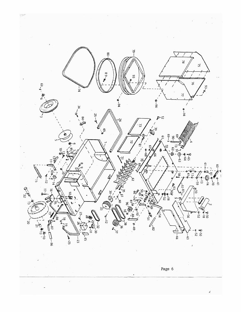
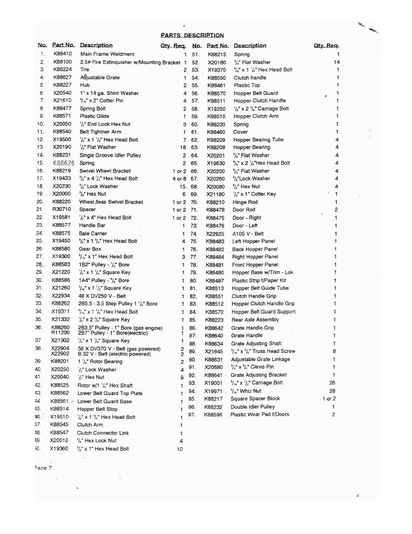
Adjustments ……………………………………5SPECIFICATIONS ……………………………………...5PARTS EXPLOSION DIAGRAMS and LISTS …….6-7
WEAVERLINE, LLC
Model No.
Serial No.
CHURCHTOWN, PA 17555-9705
Page 1

SAFETY
! WARNING:This machine is to be operated only by adults.
Read and understand this operator’s manual
completely before attempting to operate,
service or make adjustments. Prior to use,
locate all warning decals and be aware of the
safety hazards they call out.
! WARNING:Never wear loose clothing while operating this
equipment, it can become caught in moving
parts.
! WARNING:Using materials other than those listed may
result in personal injury or damage to the
machine.
! WARNING:Hydraulic fluid escaping under pressure can
penetrate the skin. Hydraulic fluid may also
infect a minor cut or opening in the skin. If
injured by escaping fluid, seek medical
attention immediately. Relive all pressure
before disconnecting lines or servicing.
Your WEAVERLINE CHOPPER or MULCHER is
designed to process only certain materials. We suggest
only the following dry materials to be processed:
Straw
Prairie Grass
Compressed hay
Marsh Hay
Hay
Grass
Leaves
Paper*Cardboard*
* Only when equipped with 76 knives.
Note: If bales are bound by wire instead of string or
plastic, remove wire before placing the bales into the
hopper.
PRE-OPERATION SAFETY CHECK
After going through the checklist above and the operator
is sure the machine is operating properly, chopping may
begin.
OPERATION
! CAUTION:On models equipped with a gas engine the
muffler and the exhaust manifold become very
hot during operation and remain hot for a
period of time after stopping the engine. Be
careful not to touch these items while they are
hot. To avoid severe burns or fire hazards, let
the engine cool before transporting or storing
this piece of equipment.
! WARNING:Be sure rotor is at rest before adjusting
discharge.
AGAIN, be sure to read this manual completelybefore operating or servicing this piece of equipment!
Keep all shields in place and carefully follow decal
instructions.
Make sure all electrical connections are secure and in
good condition. High voltage arcing can KILL.
Make sure all controls operate correctly.
Be sure that fire extinguisher is in place and fully
charged.
Check hopper for foreign objects before applying
power.
Keep others away. Make sure only the operator is
near the machine during operation.
Make sure all connections are tight and hoses in good
condition before applying pressure to the hydraulic
system.
After servicing, be sure to remove all tools and loose
objects from the machine.
Apply power to rotor and hopper. Check for
excessive noise and vibration.

CONTROLS
Figure 2 Rotor Clutch Engagement
Figure 3 Hopper Rotation Clutch
Figure 4 Adjustable Grate
To begin operation:
1. Make sure all hopper and rotor engagingmechanisms are disengaged.
2. Set grate to highest position (Figure 4.)
3. Adjust discharge to desired position.
4. Start the engine on gas powered models.
5. Turn on the electric motor, apply power onthe hydraulic unit or engage the rotor clutchon gas powered models (Figure 2.)
6. Place the first bale or other material to be
chopped into the hopper.
Note: Cut and remove strings from baleimmediately after inserting into hopper. Anysting or wire should be removed from otherbundled materials before inserting into
hopper.
7. Engage the clutch to start the hopperrotating (Figure 3)
8. Lower the grate so that the machineoperates smoothly and produces desiredlength of cut.
Note: Moving the grate lever to the right willlower the grate and moving the lever to theleft will raise the grate (Figure 4.)Adjusting the grate to a lower positiondecreases cutting time while increasingmaterial length.
9. Continue to add bales (or other material)when the hopper is 1/2 to 2/3 empty.
DURING OPERATION
To stop operation:
1. Set grate to highest position.
2. Stop hopper rotation.
3. Slowly reduce engine speed to idle.
4. Disengage rotor and or shut off powersupply.
For maintenance purposes and to reducefire hazard, clean chopped material anddebris from machine immediately after eachuse. On machines equipped with gasolineengines the fuel shut-off valve should beclosed between uses.
Always wear approved eye protection.
Do not attempt to remove any material orobstructions from hopper or rotor while machine is
running.
Never force materials onto the rotor with your hands,
feet or other objects.
Never stand in front of discharge.
Keep hands, feet, and clothing away from moving
parts.
Keep all shields and guards in place.
Carefully follow decal instructions (Replace decals
when badly worn or difficult to read.)
Do not open any covers or remove any shields while
rotor or hopper is rotating (Rotor continues to rotatemomentarily after power has been shut off.)
Page 3
SERVICE
! WARNING:Lockout power source and be sure allmoving parts have come to rest beforeperforming any service work.
CLEANING
Keeping the machine clean is an important part ofmaintenance and will help to insure proper operation.In addition to general cleaning, the rotor and engine(where applicable) should receive special attention.
ROTOR
An accumulation of materials such as baler twine orstring around the rotor can result in poor operation orpossibly even rotor or bearing failure. Any suchbuildup should be checked for and corrected prior toeach use and more often if necessary. Burning is nota method that should be used to remove materialsfrom the rotor.
GAS ENGINE
Chopping paper, straw, hay or other materials cancreate large amounts of dust. This makes itnecessary to clean the air filtering system morefrequently than recommended by the enginemanufacturer. It is best to check the filter system priorto each use but at least once a week when using thechopper on a daily basis. Refer to engine manual forcleaning instructions.
Allowing dust and debris to accumulate betweencooling fins will cause an increase in operatingtemperature. As a result engine may suffer a loss ofpower and increase the possibility of fire. A cleanengine will last longer and deliver peak performance.
Follow the engine manufacturer’s instructions foradditional maintenance procedures.
GEAR BOX
See manufacturer’s instructions.
BEARINGS
The bearings are sealed and require no lubrication.Build up of chopped material or other debris shouldbe removed often to aid in preventing prematurebearing failure. If you do choose to grease the rotorbearings, you should grease a maximum of onepump of a grease gun once every six months.
ROTOR BLADE REPLACEMENT.
Refer to separate instructions included with thismanual.
Adjustments
GRATE STOP ADJUSTMENT
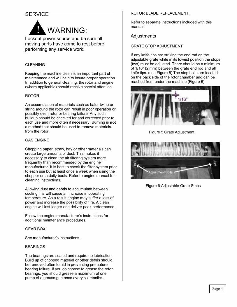
If any knife tips are striking the end rod on theadjustable grate while in its lowest position the stops(two) must be adjusted. There should be a minimumof 1/16” (2 mm) between the grate end rod and allknife tips. (see Figure 5) The stop bolts are locatedon the back side of the rotor chamber and can bereached from under the machine (Figure 6)
Figure 5 Grate Adjustment
Figure 6 Adjustable Grate Stops
Page 4

Page 5
BELT INSTALLATION
V-belts should be installed as shown in figures 7 & 8.All idler pulleys should ride on the flat side of thebelt(s). Electric powered models are not equippedwith a double idler pulley as shown in figure 7.
Figure 7 Rotor and Gear Box Drive Belt Installation
Figure 8 Hopper Belt Installation
DOOR ADJUSTMENT
If doors will not stay in the position they were settighten the lock nut shown in figure 9.
Figure 9 Door Adjusting Nut
SPECIFICATIONS
Dimensions:
Length – approximately 60” (1.52m)Width – approximately 60” (1.52m)Height – 32-34” (.81 - .86m)
Weight: 420 – 500 lbs. (190 – 227kg)