chimney vent hoods instructions
TRANSCRIPT

Write the model and serial numbers here:
Model # _________________
Serial # _________________
You can find them on a label on the inside of the hood.
49-2000916 Rev. 0 06-21
PV970PV976
OWNER’S MANUAL &INSTALLATION INSTRUCTIONS
CH
IMN
EY
VEN
T H
OO
DS SAFETY INFORMATION . . . . . . . . . . . . 3
USING THE HOODLight Controls . . . . . . . . . . . . . . . . . . . . . . . . . . . 5Vent Controls . . . . . . . . . . . . . . . . . . . . . . . . . . . 5
CARE AND CLEANINGGrease Filter . . . . . . . . . . . . . . . . . . . . . . . . . . . . 6 Stainless Steel Surfaces . . . . . . . . . . . . . . . . . . . 7 LED Lights . . . . . . . . . . . . . . . . . . . . . . . . . . . . . . 7
INSTALLATION INSTRUCTIONS . . 8Installation Preparation . . . . . . . . . . . . . . . . . . . 9 Vented to the Outside . . . . . . . . . . . . . . . . . . . .14 Recirculating . . . . . . . . . . . . . . . . . . . . . . . . . . . .18
TROUBLESHOOTING TIPS . . . . . . . . 23
LIMITED WARRANTY . . . . . . . . . . . . . 25
CONSUMER SUPPORT . . . . . . . . . . . . 26
ENGLISH/ESPAÑOL

2 49-2000916 Rev. 0
THANK YOU FOR MAKING GE APPLIANCES A PART OF YOUR HOME.
Whether you grew up with GE Appliances, or this is your first, we’re happy to have you in the family.
We take pride in the craftsmanship, innovation and design that goes into every GE Appliances product, and we think you will too. Among other things, registration of your appliance ensures that we
can deliver important product information and warranty details when you need them.
Register your GE appliance now online. Helpful websites and phone numbers are available in the Consumer Support section of this Owner’s Manual. You may also mail in the pre-printed registration
card included in the packing material.
49-2000916 Rev. 0 3
SAFETY IN
FOR
MA
TION
READ AND SAVE THESE INSTRUCTIONS
IMPORTANT SAFETY INFORMATIONREAD ALL INSTRUCTIONS BEFORE USING THE APPLIANCE
WARNING TO REDUCE THE RISK OF FIRE, ELECTRIC SHOCK OR INJURY TO PERSONS, OBSERVE THE FOLLOWING:A. Use this unit only in the manner intended by the
manufacturer. If you have questions, contact the manufacturer.
B. Before servicing or cleaning unit, switch power off at service panel and lock the service disconnecting means to prevent power from being switched on accidentally. When the service disconnecting means cannot be locked, securely fasten a prominent warning device, such as a tag, to the service panel.
C. Do not use this unit with any solid-state speed control device.
D. This unit must be grounded.
CAUTION For general ventilating use only. Do not use to exhaust hazardous or explosive materials and vapors.
CAUTION To reduce risk of fire and to properly exhaust air, be sure to duct air outside. Do not vent exhaust air into spaces within walls or ceilings or into attics, crawl spaces or garages.
WARNING TO REDUCE THE RISK OF INJURY TO PERSONS IN THE EVENT OF A RANGE TOP GREASE FIRE, OBSERVE THE FOLLOWING*:A. SMOTHER FLAMES with a close-fitting lid, cookie
sheet or metal tray, then turn off the burner. BE CAREFUL TO PREVENT BURNS. If the flames do not go out immediately, EVACUATE AND CALL THE FIRE DEPARTMENT.
B. NEVER PICK UP A FLAMING PAN— You may be burned.
C. DO NOT USE WATER, including wet dishcloths or towels - a violent steam explosion will result.
D. Use an extinguisher ONLY if: 1. You know you have a Class ABC extinguisher,
and you already know how to operate it. 2. The fire is small and contained in the area where
it started. 3. The fire department is being called. 4. You can fight the fire with your back to an exit.* Based on “Kitchen Fire Safety Tips” published by
NFPA.

4 49-2000916 Rev. 0
SAFE
TY IN
FOR
MA
TIO
N
READ AND SAVE THESE INSTRUCTIONS
IMPORTANT SAFETY INFORMATIONREAD ALL INSTRUCTIONS BEFORE USING THE APPLIANCE
WARNING TO REDUCE THE RISK OF A RANGE TOP GREASE FIRE:A. Never leave surface units unattended at high
settings. Boilovers cause smoking and greasy spillovers that may ignite. Heat oils slowly on low or medium settings.
B. Always turn hood ON when cooking on high heat or when flambéing food (i.e. Crepes Suzette, Cherries Jubilee, Peppercorn Beef Flambé).
C. Clean ventilating fans frequently. Grease should not be allowed to accumulate on fan or filter.
D. Use proper pan size. Always use cookware appropriate for the size of the surface element.
WARNING TO REDUCE THE RISK OF FIRE, ELECTRIC SHOCK OR INJURY TO PERSONS, OBSERVE THE FOLLOWING:A. Installation work and electrical wiring must be
done by qualified person(s) in accordance with all applicable codes and standards, including fire-rated construction.
B. Sufficient air is needed for proper combustion and exhausting of gases through the flue (chimney) of fuel burning equipment to prevent back drafting. Follow the heating equipment manufacturer’s guidelines and safety standards, such as those published by the National Fire Protection Association (NFPA), the American Society for Heating, Refrigeration and Air Conditioning Engineers (ASHRAE) and the local code authorities. When applicable, install any makeup (replacement) air system in accordance with local building code requirements. Visit GEAppliances.com for available makeup air solutions.
C. When cutting or drilling into wall or ceiling, do not damage electrical wiring and other hidden utilities.
D. Ducted fans must always be vented to the outdoors.F. Turn off breaker to adjacent rooms while working.
WARNING TO REDUCE THE RISK OF FIRE, USE ONLY METAL DUCTWORK.
Do not attempt to repair or replace any part of your hood unless it is specifically recommended in this manual. All other servicing should be referred to a qualified technician.
49-2000916 Rev. 0 5
ControlsU
SING
THE H
OO
D: C
ontrols
3 2 1
1. MEMORY/OFF: To set the memory: A. Press the MEMORY/OFF button. B. Set your desired fan and light settings. C. Press the MEMORY/OFF button again to save
these settings. With your desired settings in memory, press the
MEMORY/OFF button to restore the fan and light levels to their saved settings. These settings will remain in memory until they are changed or loss of power occurs.
To turn off the hood, press the MEMORY/OFF button.2. LIGHT: Press + or – to increase or decrease light
level to desired setting. There are 2 light levels (LOW, HIGH) and OFF. If you continue to press the + or – buttons, the light will cycle back through the settings.
3. FAN. Press + or – to increase or decrease fan level to your desired setting. There are 4 fan levels (LOW, MED, HIGH, BOOST) and OFF. If you continue to press the + or – buttons, the fan will cycle back through the settings.
NOTE: There is an audible “beep” each time a button is pressed. This is normal.
NOTE: The collars around the buttons will illuminate when pressed. This is normal. The collars will automatically turn off if the hood is turned off.
HEAT SENSOR: This hood is equipped with a heat sensor that will turn on the fan if excessive temperatures are detected (over
return to its normal operation once the heat sensor
NOTE: If the hood is OFF or on LOW fan speed, the
fan will automatically adjust to MED speed. You may adjust the fan speed to HIGH or BOOST, but you will not be able to adjust the fan speed to LOW or OFF until
NOTE: The collars around the buttons may not illuminate if the heat sensor is activated. This is normal.

6 49-2000916 Rev. 0
FiltersC
AR
E A
ND
CLE
AN
ING
: Filt
ers
Metal Grease FilterThe metal filter traps grease released by foods from the cooktop. The filter also helps prevent flames (from food, grease) from damaging the inside of the hood.For this reason, the filter must ALWAYS be in place when the hood is in use. The grease filter is dishwasher-safe and should be cleaned every 6 months, or as needed.
To remove: Pull downward on the filter lock to release the filter.To replace:Fit the tabs at the end of the filter into the slots in left side of the filter opening. Lift up the right side of the filter and push gently until the filter locks into place. Make sure the filter lock is in the closed position to secure the filter.To clean, swish the filter in hot soapy water and rinse in clean water or wash it in the dishwasher. Do not use abrasive cleansers.NOTE: Some discoloration will occur in the dishwasher.
Charcoal FilterFor recirculating installation onlyIf the model is not vented to the outside, the air will be recirculated through a disposable charcoal filter that helps remove smoke and odors.The charcoal filter should be replaced when it is noticeably dirty or discolored (usually after 6 to 12 months, depending on hood usage).NOTE: DO NOT rinse, or put charcoal filter in an automatic dishwasher.The charcoal filter cannot be cleaned. It must be replaced.
To inquire about purchasing replacement charcoal filters or to find the location of a dealer nearest you, please call our toll-free number:
To remove:1. Remove the metal filter—see Metal grease filter
section.2. Remove the charcoal filter by pushing in on both
locking tab handles to release.To replace:1. Insert the charcoal filter into the opening. Push the
locking tab handles toward the center and release to engage the locking tabs.
2. Replace the metal filter—see Metal grease filter section.
Be sure electrical power is off and all surfaces are cool before cleaning or servicing any part of the vent hood.
Locking tab handle
Locking tab handle
49-2000916 Rev. 0 7
Care and CleaningStainless Steel Surfaces
To clean the stainless steel surface, use warm sudsy water or a stainless steel cleaner or polish. Always wipe the surface in the direction of the brush line. Follow the cleaner instructions for cleaning the stainless steel surface. Cleaners with oxalic acid such as Bar Keepers Friend Soft Cleanser™ will remove surface rust, tarnish, and small blemishes. To receive a $2.00 coupon for a trial sample of Bar Keepers Friend Soft Cleanser™ follow the link below or scan the QR Code.barkeepersfriend.com/ge
Use only a liquid cleanser free of grit and rub in the direction of the brush lines with a damp soft sponge. To inquire about purchasing stainless steel appliance cleaner or polish, or to find the location of a dealer nearest you, please call our toll-free number:
GEApplianceParts.com
CA
RE A
ND
CLEA
NIN
G
LED LightsThe LED lights are replaceable by a service technician only. See the Limited Warranty section for service contact information.

49-2000916 Rev. 0
Installation Instructions
If you have questions, call GE Appliances at 800.GE.CARES (800.432.2737) or visit our website at: GEAppliances.com
BEFORE YOU BEGINRead these instructions completely and carefully.
IMPORTANT – Save these instructions for local inspector’s use.
IMPORTANT – Observe all governing codes and ordinances.
Note to Installer – Be sure to leave these instructions with the Consumer.
Note to Consumer – Keep these instructions for future reference.
Skill level – Installation of this vent hood requires basic mechanical and electrical skills.
Completion time – Approximately 1 to 3 hours
Proper installation is the responsibility of the installer.
Product failure due to improper installation is not covered under the Limited Warranty.
PRODUCT DIMENSIONS
Chimney Vent Hood
INST
ALL
ATIO
N IN
STR
UC
TIO
NS
CAUTION Due to the weight and size of these vent hoods and to reduce the risk of personal injury or damage to the product, TWO PEOPLE ARE REQUIRED FOR PROPER INSTALLATION.
FOR YOUR SAFETY:
WARNING Before beginning the installation, switch power off at service panel and lock the service disconnecting means to prevent power from being switched on accidentally. When the service disconnecting means cannot be locked, securely fasten a prominent warning device, such as a tag, to the service panel.
30” Models Require a 30” Wide Opening
”
*Height to ceiling
”29
10-7
13-1
2- ”
*Height to CeilingVented Recirculating
MinMax
36” Models Require a 36” Wide Opening
* For supplied duct cover ceiling heights for vented installation and recirculating installation, refer to the table on page 13.
Allow 1” overlap of duct.
*Height to CeilingVented Recirculating
MinMax
*Height to Ceiling

49-2000916 Rev. 0 9
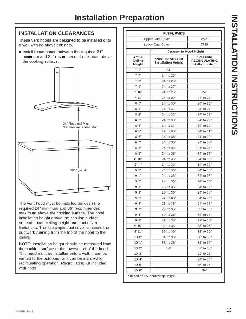
INSTALLATION CLEARANCES These vent hoods are designed to be installed onto a wall. They may be installed beneath a soffit or cabinet.
minimum and 36” recommended maximum above the cooking surface.
The vent hood must be installed between the required 24” minimum and 36” recommended maximum above the cooking surface. The hood installation height above the cooking surface depends upon ceiling height and duct cover limitations. The telescopic duct cover conceals the ductwork running from the top of the hood to the ceiling. For supplied duct cover ceiling heights, see table on page 13. Recirculation Kit: Kit includes 1 air deflector and 1 charcoal filter and is included with the hood.NOTE: Installation height should be measured from the cooking surface to the lowest part of the hood. This hood must be installed onto a wall. It can be vented to the outdoors, or it can be installed for recirculating operation. For recirculation operation, a Recirculating Kit (included) is required.
INSTA
LLATION
INSTR
UC
TION
SInstallation Preparation
PREPARE TO INSTALL THE HOODADVANCE PLANNINGDuct Install Planning
This hood is designed to be vented vertically through the ceiling. A duct transition piece is supplied for vertical exhaust. Use locally supplied elbows to vent horizontally through the rear wall.
Use metal ductwork only. Determine the exact location of the vent hood. Plan the route for venting exhaust to the
outdoors. To maximize the ventilation performance of the vent system:
1. Minimize the duct run length and number of transitions and elbows.
2. Maintain a constant duct size.3. Seal all joints with duct tape to prevent any
leaks.4. Do not use any type of flexible ducting.
Use the shortest and straightest duct route possible.
Install a wall cap or roof cap with damper at the exterior opening. Order the wall or roof cap and any transitions and length of duct needed in advance.
When applicable, install any makeup (replacement) air system in accordance with local building code requirements. Visit GEAppliances.com for available makeup air solutions.
Wall Framing for Adequate Support This vent hood is heavy. Adequate structural
support must be provided. The hood must be secured to vertical studs in the wall. See page 14.
We strongly recommend that the vent hood with duct cover be on site before final framing and wall finishing. This will also help to accurately locate the ductwork and electrical service.
24” Required Min. 36” Recommended Max.
10 49-2000916 Rev. 0
Installation PreparationIN
STA
LLA
TIO
N IN
STR
UC
TIO
NS
POWER SUPPLYIMPORTANT—(Please read carefully)
WARNING FOR PERSONAL SAFETY, THIS APPLIANCE MUST BE PROPERLY GROUNDED.Remove house fuse or open circuit breaker before beginning installation.Do not use an extension cord or adapter plug with this appliance. Follow National Electrical Codes or prevailing local codes and ordinances.Electrical SupplyThis vent hood must be supplied with 120V, 60Hz, and connected to an individual, properly grounded branch circuit, and protected by a 15 or 20 amp circuit breaker or time delay fuse.
requirements, call a licensed electrician before proceeding.
location as possible in the ceiling or wall. See page 14 for details.
accordance with local codes.Grounding InstructionsThe grounding conductor must be connected to a ground metal, permanent wiring system, or an equipment-grounding terminal or lead on the hood.
WARNING The improper connection of equipment-grounding conductor can result in a risk of electric shock. Check with a qualified electrician or service representative if you are in doubt whether the appliance is properly grounded.
This Hood MUST Use an 8” Round Duct. It Can Transition to a 3-1/4” x 12” Duct.
DO NOT use flexible plastic ducting.NOTE: Any home ventilation system, such as a ventilation hood, may interrupt the proper flow of combustion air and exhaust required by fireplaces, gas furnaces, gas water heaters and other naturally vented systems. To minimize the chance of interruption of such naturally vented systems, follow the heating equipment manufacturer’s guidelines and safety standards such as those published by NFPA and ASHRAE. When applicable, install any makeup (replacement) air system in accordance with local building code requirements. Visit GEAppliances.com for available makeup air solutions.

49-2000916 Rev. 0 11
Installation Preparation
REMOVE THE PACKAGING CAUTION Wear gloves to protect against
sharp edges.
other boxed parts.
plastic wrapping and other packaging materials.
TOOLS AND MATERIALS REQUIRED (NOT SUPPLIED)
Pliers
Metal snips
Spirit level
Aluminized Duct tape
Safety glasses
120V 60Hz. 15 or 20 Amp, 2-wire with ground, properly grounded branch circuit
Step ladder
Saber saw or Key Hole saw
Phillips screwdriver
Strain relief forjunction box
duct, length to suit installation
Hammer
bits, #2 Phillips head
Flashlight
UL listed wire nuts
Pencil and tape measure
INSTA
LLATION
INSTR
UC
TION
S
12 49-2000916 Rev. 0
Installation Preparation
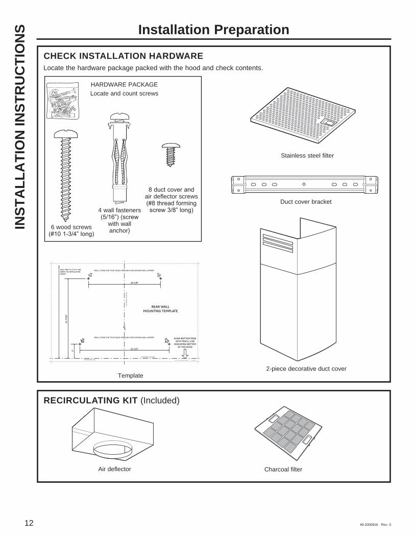
CHECK INSTALLATION HARDWARE Locate the hardware package packed with the hood and check contents.
RECIRCULATING KIT (Included)
Air deflector Charcoal filter
Template
Stainless steel filter
INST
ALL
ATI
ON
INST
RU
CTI
ON
S
REAR WALLMOUNTING TEMPLATE
VerticalCenterline
ALIGN BOTTOM EDGEWITH PENCIL LINE
INDICATING BOTTOMOF THE HOOD
11-7
/16"
Installation HeightHorizontal Line
CL
DRILL 2 (TWO) 3/16" PILOT HOLES THROUGH STUDS OR REAR WALL SUPPORT
10-1/8"
12-08 JR
2"
DRILL 2 (TWO) 3/16" PILOT HOLES THROUGH STUDS OR REAR WALL SUPPORT
12-1/2"
WALL VENT IS 27-3/4" MIN.ABOVE THE INSTALLATIONHEIGHT
31-14772 Printed in Mexico
HARDWARE PACKAGELocate and count screws
6 wood screws
4 wall fasteners
with wall anchor)
air deflector screws Duct cover bracket
2-piece decorative duct cover
49-2000916 Rev. 0 13
INSTA
LLATION
INSTR
UC
TION
SInstallation Preparation
INSTALLATION CLEARANCESThese vent hoods are designed to be installed onto a wall with no above cabinets.
minimum and 36” recommended maximum above the cooking surface.
The vent hood must be installed between the required 24” minimum and 36” recommended maximum above the cooking surface. The hood installation height above the cooking surface depends upon ceiling height and duct cover limitations. The telescopic duct cover conceals the ductwork running from the top of the hood to the ceiling.NOTE: Installation height should be measured from the cooking surface to the lowest part of the hood. This hood must be installed onto a wall. It can be vented to the outdoors, or it can be installed for recirculating operation. Recirculating Kit included with hood.
24” Required Min. 36” Recommended Max.
36” Typical
PV970, PV976Upper Duct Cover
Lower Duct Cover 27.56
Counter to Hood HeightActual Ceiling Height
*Possible VENTED Installation Height
*Possible RECIRCULATING Installation Height
7' 6" 24"
7' 7" 24" to 25"
24" to 26"
7' 9" 24" to 27"
7' 10" 24"
7' 11" 24" to 29" 24" to 25"
24" to 30" 24" to 26"
24" to 31" 24" to 27"
24" to 32"
24" to 33" 24" to 29"
24" to 34" 24" to 30"
24" to 35" 24" to 31"
24" to 36" 24" to 32"
24" to 36" 24" to 33"
24" to 36" 24" to 34"
24" to 36" 24" to 35"
24" to 36" 24" to 36"
24" to 36" 24" to 36"
9' 0" 24" to 36" 24" to 36"
9' 1" 24" to 36" 24" to 36"
9' 2" 24" to 36" 24" to 36"
9' 3" 25" to 36" 24" to 36"
9' 4" 26" to 36" 24" to 36"
9' 5" 27" to 36" 24" to 36"
9' 6" 24" to 36"
9' 7" 29" to 36" 25" to 36"
30" to 36" 26" to 36"
9' 9" 31" to 36" 27" to 36"
9' 10" 32" to 36"
9' 11" 33" to 36" 29" to 36"
10' 0" 34" to 36" 30" to 36"
10' 1" 35" to 36" 31" to 36"
10' 2" 36" 32" to 36"
10' 3" 33" to 36"
10' 4" 34" to 36"
10' 5" 35" to 36"
10' 6" 36"
* based on 36” countertop height
14 49-2000916 Rev. 0
Installation InstructionsIN
STA
LLA
TIO
N IN
STR
UC
TIO
NS
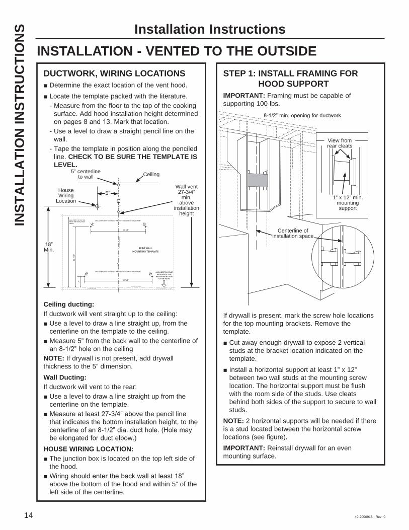
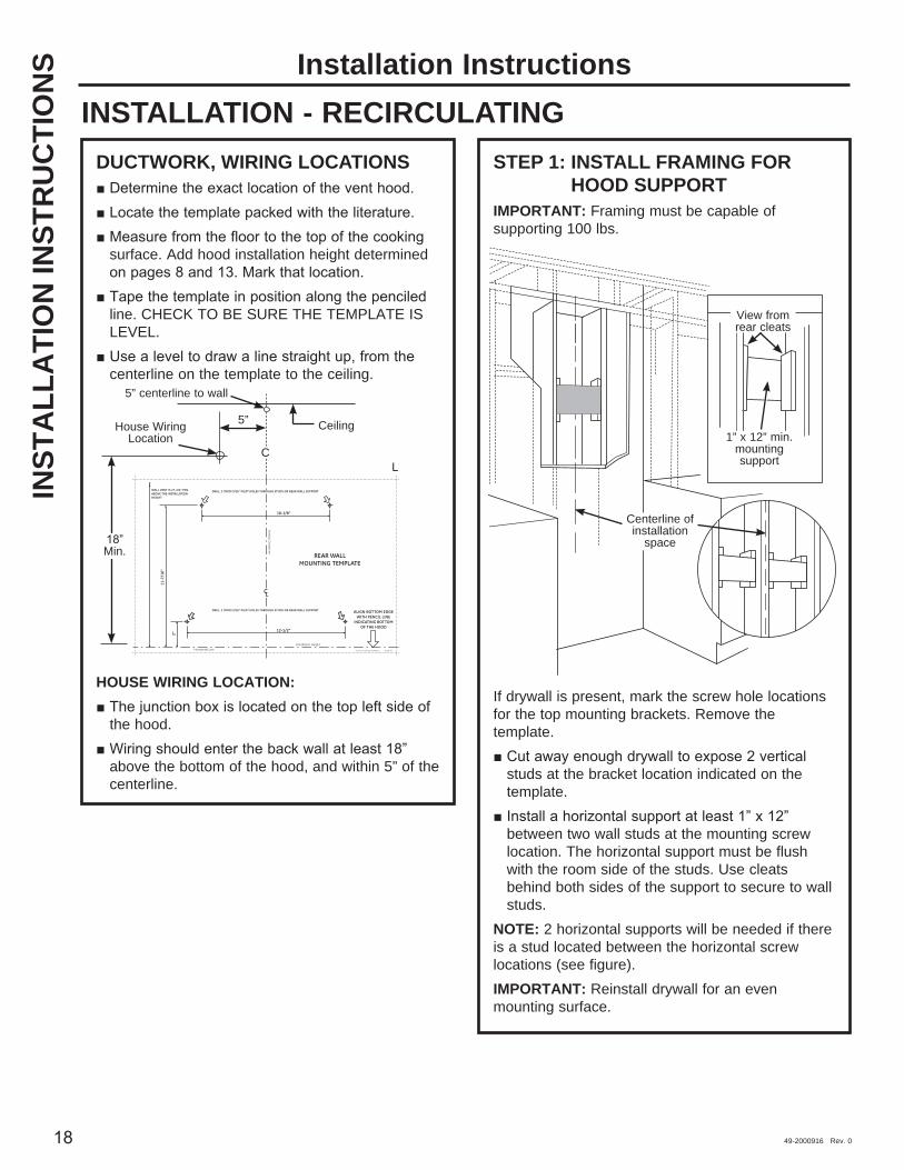
INSTALLATION - VENTED TO THE OUTSIDEDUCTWORK, WIRING LOCATIONS
Determine the exact location of the vent hood. Locate the template packed with the literature.
- Measure from the floor to the top of the cooking surface. Add hood installation height determined
- Use a level to draw a straight pencil line on the wall.
- Tape the template in position along the penciled line. CHECK TO BE SURE THE TEMPLATE IS LEVEL.
Ceiling ducting:If ductwork will vent straight up to the ceiling:
Use a level to draw a line straight up, from the centerline on the template to the ceiling.
Measure 5” from the back wall to the centerline of
NOTE: If drywall is not present, add drywall thickness to the 5” dimension.Wall Ducting:If ductwork will vent to the rear:
Use a level to draw a line straight up from the centerline on the template.
that indicates the bottom installation height, to the
be elongated for duct elbow.)HOUSE WIRING LOCATION:
The junction box is located on the top left side of the hood.
above the bottom of the hood and within 5” of the left side of the centerline.
STEP 1: INSTALL FRAMING FOR HOOD SUPPORT
IMPORTANT: Framing must be capable of supporting 100 lbs.
If drywall is present, mark the screw hole locations for the top mounting brackets. Remove the template.
Cut away enough drywall to expose 2 vertical studs at the bracket location indicated on the template.
Install a horizontal support at least 1” x 12” between two wall studs at the mounting screw location. The horizontal support must be flush with the room side of the studs. Use cleats behind both sides of the support to secure to wall studs.
NOTE: 2 horizontal supports will be needed if there is a stud located between the horizontal screw locations (see figure).IMPORTANT: Reinstall drywall for an even mounting surface.
REAR WALLMOUNTING TEMPLATE
VerticalCenterline
ALIGN BOTTOM EDGEWITH PENCIL LINE
INDICATING BOTTOMOF THE HOOD
11-7
/16"
Installation HeightHorizontal Line
CL
DRILL 2 (TWO) 3/16" PILOT HOLES THROUGH STUDS OR REAR WALL SUPPORT
10-1/8"
12-08 JR
2"
DRILL 2 (TWO) 3/16" PILOT HOLES THROUGH STUDS OR REAR WALL SUPPORT
12-1/2"
WALL VENT IS 27-3/4" MIN.ABOVE THE INSTALLATIONHEIGHT
31-14772 Printed in Mexico
Ceiling
House Wiring
Location CL
5”
Min.
Wall vent
min. above
installation height
5” c enterline to wall
View from rear cleats
1” x 12” min. mounting support
Centerline of installation space
49-2000916 Rev. 0 15
Installation InstructionsINSTALLATION - VENTED TO THE OUTSIDE (Cont.)
STEP 2: INSTALL HOOD MOUNTING SCREWS
The two upper mounting screws must enter the horizontal support or wall studs.
mark mounting bracket screw locations.
in the lower bracket. If the bottom 2 pilot holes
install metal wall fastener anchors (provided).
gap between the screw head and the wall. This will allow the keyhole slot on the hood frame to engage the screw head.
IMPORTANT: Use the mounting screws provided. DO NOT USE DRYWALL SCREWS.
horizontally level.
STEP 3: INSTALL DUCT BRACKETThe duct bracket should be installed against the
the ceiling meets the wall should be level for the bracket and duct cover to fit flush. This bracket will hold the duct cover in place at the top.Secure the bracket to the wall:
bracket with the penciled centerline on the wall.
anchors (provided).
appropriate #10 masonry screw anchors. Drill and install per the fastener supplier’s instructions.
anchors to expand. Remove the screws.
STEP 4: MOUNT THE HOODWARNING 2 people are required to lift and
position the hood onto the mounting screws.
in front of the flange and not behind it. Check with a level before tightening the screws.
the wall.
INSTA
LLATION
INSTR
UC
TION
S
REAR WALLMOUNTING TEMPLATE
VerticalCenterline
ALIGN BOTTOM EDGEWITH PENCIL LINE
INDICATING BOTTOMOF THE HOOD
11-7
/16"
Installation HeightHorizontal Line
CL
DRILL 2 (TWO) 3/16" PILOT HOLES THROUGH STUDS OR REAR WALL SUPPORT
10-1/8"
12-08 JR
2"
DRILL 2 (TWO) 3/16" PILOT HOLES THROUGH STUDS OR REAR WALL SUPPORT
12-1/2"
WALL VENT IS 27-3/4" MIN.ABOVE THE INSTALLATIONHEIGHT
31-14772 Printed in Mexico
Centerline cutout
Tighten screws
Install screws
Bottom screw
location

16 49-2000916 Rev. 0
Installation InstructionsIN
STA
LLA
TIO
N IN
STR
UC
TIO
NS
INSTALLATION - VENTED TO THE OUTSIDE (Cont.)
STEP 5: CONNECT DUCTWORK Remove shipping tape from the damper. Install ductwork, making connections in the direction of airflow as illustrated.
Push duct over the exhaust outlet and damper. Secure joints in ductwork with sheet metal screws.
Wrap all duct joints and the flange connections with aluminized duct tape for an airtight seal.
CAUTION Do not use sheet metal screws at the hood flange connection. Doing so will prevent proper damper operation. Seal connection with tape only.
STEP 6: CONNECT ELECTRICALVerify that power is turned off at the source.
WARNING If house wiring is not 2-wire with a ground wire, a ground must be provided by the installer. When house wiring is aluminum, be sure to use U.L. approved anti-oxidant compound and aluminum-to-copper connectors.
Remove the 6 screws on the junction box cover and the knockout on the top left side.
STEP 6: CONNECT ELECTRICAL (cont.)
a strain relief (not provided).
lead.
lead.
circuit green lead or bare ground lead.
electrical connector.
the cover. Be sure the wires are not pinched.
screws.
Duct tape over seam and
screw
Screw
Airflow
Junction box cover
Knockout
49-2000916 Rev. 0 17
Installation InstructionsINSTALLATION - VENTED TO THE OUTSIDE (Cont.)
INSTA
LLATION
INSTR
UC
TION
S
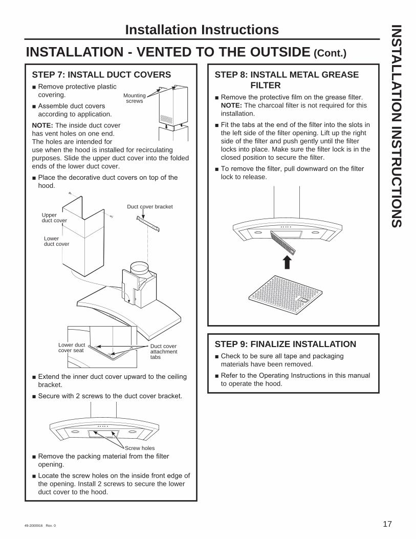
STEP 7: INSTALL DUCT COVERS
covering.
according to application.NOTE: The inside duct cover has vent holes on one end. The holes are intended for use when the hood is installed for recirculating purposes. Slide the upper duct cover into the folded ends of the lower duct cover.
hood.
bracket.
opening.
the opening. Install 2 screws to secure the lower duct cover to the hood.
STEP 8: INSTALL METAL GREASE FILTER
NOTE: The charcoal filter is not required for this installation.
the left side of the filter opening. Lift up the right side of the filter and push gently until the filter locks into place. Make sure the filter lock is in the closed position to secure the filter.
lock to release.
STEP 9: FINALIZE INSTALLATION
materials have been removed.
to operate the hood.
Mounting screws
Lower duct cover seat
Duct cover bracket
Lower duct cover
Upper duct cover
Duct cover attachment tabs
Screw holes
49-2000916 Rev. 0
Installation InstructionsIN
STA
LLA
TIO
N IN
STR
UC
TIO
NS
INSTALLATION - RECIRCULATINGDUCTWORK, WIRING LOCATIONS
surface. Add hood installation height determined
line. CHECK TO BE SURE THE TEMPLATE IS LEVEL.
centerline on the template to the ceiling.
HOUSE WIRING LOCATION:
the hood.
above the bottom of the hood, and within 5” of the centerline.
STEP 1: INSTALL FRAMING FOR HOOD SUPPORT
IMPORTANT: Framing must be capable of supporting 100 lbs.
If drywall is present, mark the screw hole locations for the top mounting brackets. Remove the template.
studs at the bracket location indicated on the template.
between two wall studs at the mounting screw location. The horizontal support must be flush with the room side of the studs. Use cleats behind both sides of the support to secure to wall studs.
NOTE: 2 horizontal supports will be needed if there is a stud located between the horizontal screw locations (see figure).IMPORTANT: Reinstall drywall for an even mounting surface.
REAR WALLMOUNTING TEMPLATE
VerticalCenterline
ALIGN BOTTOM EDGEWITH PENCIL LINE
INDICATING BOTTOMOF THE HOOD
11-7
/16"
Installation HeightHorizontal Line
CL
DRILL 2 (TWO) 3/16" PILOT HOLES THROUGH STUDS OR REAR WALL SUPPORT
10-1/8"
12-08 JR
2"
DRILL 2 (TWO) 3/16" PILOT HOLES THROUGH STUDS OR REAR WALL SUPPORT
12-1/2"
WALL VENT IS 27-3/4" MIN.ABOVE THE INSTALLATIONHEIGHT
31-14772 Printed in Mexico
CeilingHouse Wiring Location
CL
5”
Min.
5” c enterline to wall
View from rear cleats
1” x 12” min. mounting support
Centerline of installation
space
49-2000916 Rev. 0 19
Installation InstructionsINSTALLATION - RECIRCULATING (Cont.)
INSTA
LLATION
INSTR
UC
TION
S
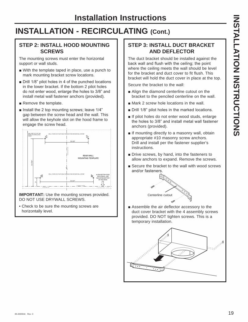
STEP 2: INSTALL HOOD MOUNTING SCREWS
The mounting screws must enter the horizontal support or wall studs.
With the template taped in place, use a punch to mark mounting bracket screw locations.
in the lower bracket. If the bottom 2 pilot holes
install metal wall fastener anchors (provided). Remove the template.
gap between the screw head and the wall. This will allow the keyhole slot on the hood frame to engage the screw head.
IMPORTANT: Use the mounting screws provided. DO NOT USE DRYWALL SCREWS.• Check to be sure the mounting screws are
horizontally level.
STEP 3: INSTALL DUCT BRACKET AND DEFLECTOR
The duct bracket should be installed against the
where the ceiling meets the wall should be level for the bracket and duct cover to fit flush. This bracket will hold the duct cover in place at the top.Secure the bracket to the wall:
Align the diamond centerline cutout on the bracket to the penciled centerline on the wall.
Mark 2 screw hole locations in the wall. If pilot holes do not enter wood studs, enlarge
anchors (provided). If mounting directly to a masonry wall, obtain appropriate #10 masonry screw anchors. Drill and install per the fastener supplier’s instructions.
Drive screws, by hand, into the fasteners to allow anchors to expand. Remove the screws.
Secure the bracket to the wall with wood screws
Assemble the air deflector accessory to the duct cover bracket with the 4 assembly screws provided. DO NOT tighten screws. This is a temporary installation.
REAR WALLMOUNTING TEMPLATE
VerticalCenterline
ALIGN BOTTOM EDGEWITH PENCIL LINE
INDICATING BOTTOMOF THE HOOD
11-7
/16"
Installation HeightHorizontal Line
CL
DRILL 2 (TWO) 3/16" PILOT HOLES THROUGH STUDS OR REAR WALL SUPPORT
10-1/8"
12-08 JR
2"
DRILL 2 (TWO) 3/16" PILOT HOLES THROUGH STUDS OR REAR WALL SUPPORT
12-1/2"
WALL VENT IS 27-3/4" MIN.ABOVE THE INSTALLATIONHEIGHT
31-14772 Printed in Mexico
Centerline cutout

20 49-2000916 Rev. 0
Installation InstructionsINSTALLATION - RECIRCULATING (Cont.)
STEP 4: MOUNT THE HOODWARNING 2 people are required to lift and
position the hood onto the mounting screws. Lift the hood onto the mounting screws.
in front of the flange and not behind it. Check with a level before tightening screws.
the wall.
STEP 5: SIZE AND CUT DUCT PIECE Measure from the bottom of the air deflector to the top of the hood as shown. Reduce that dimension by 1” to facilitate installation. The duct will cover and overlap the deflector and the exhaust outlet in the hood.
bracket.
bottom of the deflector.
exhaust outlet.
the deflector and into the bracket.
at the exhaust outlet.
INST
ALL
ATI
ON
INST
RU
CTI
ON
S
Tighten screws
Install screwsBottom
screw location
Measure length
Duct length
Deflector
49-2000916 Rev. 0 21
Installation InstructionsINSTALLATION - RECIRCULATING (Cont.)
INSTA
LLATION
INSTR
UC
TION
S
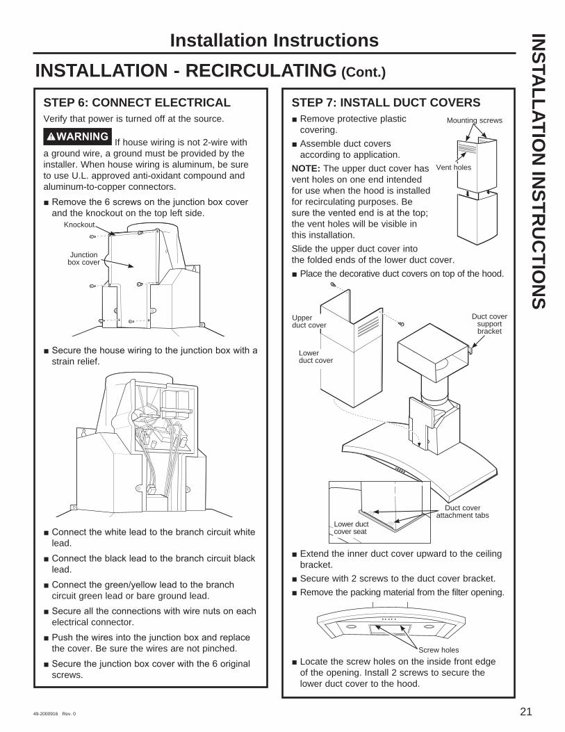
STEP 6: CONNECT ELECTRICALVerify that power is turned off at the source.
WARNING If house wiring is not 2-wire with a ground wire, a ground must be provided by the installer. When house wiring is aluminum, be sure to use U.L. approved anti-oxidant compound and aluminum-to-copper connectors.
and the knockout on the top left side.
strain relief.
lead.
lead.
circuit green lead or bare ground lead.
electrical connector.
the cover. Be sure the wires are not pinched.
screws.
STEP 7: INSTALL DUCT COVERS Remove protective plastic covering.
Assemble duct covers according to application.
NOTE: The upper duct cover has vent holes on one end intended for use when the hood is installed for recirculating purposes. Be
the vent holes will be visible in this installation. Slide the upper duct cover into the folded ends of the lower duct cover.
Place the decorative duct covers on top of the hood.
Extend the inner duct cover upward to the ceiling bracket.
Secure with 2 screws to the duct cover bracket. Remove the packing material from the filter opening.
Locate the screw holes on the inside front edge of the opening. Install 2 screws to secure the lower duct cover to the hood.
Junction box cover
Knockout
Mounting screws
Vent holes
Lower duct cover seat
Duct cover support bracket
Lower duct cover
Upper duct cover
Duct cover attachment tabs
Screw holes

22 49-2000916 Rev. 0
Installation InstructionsINSTALLATION - RECIRCULATING (Cont.)
STEP 8: INSTALL FILTERSCharcoal FilterInsert the charcoal filter into the opening. Push the latch on both sides toward the center and engage the flange.
Metal Grease Filter
in left side of the filter opening. Lift up the right side of the filter and push gently until the filter locks into place. Make sure the filter lock is in the closed position to secure the filter.
lock to release.
STEP 9: FINALIZE INSTALLATION Remove all tape and packaging materials.
manual to operate the hood.
INST
ALL
ATI
ON
INST
RU
CTI
ON
S

49-2000916 Rev. 0 23
Save time and money! Review the charts on the following pages first and you may not need to call for service.
Troubleshooting tips ... Before you call for service
Problem Possible Cause What To DoFan/Light does not operate when either button is pressed
A house fuse may be blown or a circuit breaker tripped.
Replace fuse or reset circuit breaker.
Fan does not operate when fan + or – buttonsor MEMORY/OFF button is pressed
The blower connector is loose or not plugged into its mating connector.
Disconnect power to the unit. Remove the filters and look up at the blower. If the blower connector plug is loose or you see the connector dangling, the installer failed to plug it in securely. See the Installation Instructions for the plug location and how to plug in the connector.
Loud or abnormal airflow noise
Wrong duct size used in installation. Using smaller duct pipe will cause improper venting. GE
Appliances service technicians cannot correct this issue if installed improperly.
Fan fails to circulate air or moves air slower than normal and/or fan is making loud or abnormal airflow noise
Obstructions in duct work. Make sure nothing is blocking the vent. Make sureflip over and will not fully open when this happens. Adjust to original position.
Damper blade on wall or roof cap may not be open.
Make sure damper swings freely. Damper blades may flip over and will not fully open when this happens. Adjust to original position.
Metal grease filter and charcoal filter (if present) may be dirty.
Clean the metal grease filter and replace charcoal filter (if present). See Care and Cleaning of the Vent Hood.
Insufficient makeup (replacement) air
Sufficient makeup (replacement) air is required for exhausting appliances to operate to rating. Check with local building codes, which may require or strongly advise the use of makeup air. Visit GEAppliances.com for available makeup air solutions.
The hood controls are not operating correctly
Control logic confused. Disconnect power to the hood by resetting the circuit breaker. Wait 30 seconds to allow controls to reset.
Hood does not appear to operate when the MEMORY/OFF button is pressed. All collars around the push buttons are illuminated.
The memory feature of this hood has not been set. This is normal. Adjust the Fan and Light settings to your preference.
Fan turned on by itself and is in MED setting. The fan setting can be adjusted but not to OFF.
The heat sensor is activated. This is normal when temperatures below the hood are exceeding the heat sensor limits. Remove the heat source under the hood or wait until the hood cools to appropriate levels. The hood will automatically turn itself off or return to its original setting once the heat sensor detects the temperature has reached a safe condition.
A collar around a push button is not illuminating when pressed.
Push button may be stuck. Check affected push button and ensure that it is not stuck. Call for service if problem persists.
Two or more collars around the push buttons are not illuminating when pressed.
Two or more push buttons may be stuck.
Check affected push buttons and ensure that they are not stuck. Call for service if problem persists.
Sequential presses of the LIGHT or FAN buttons will change the setting from lowest setting to OFF, tohighest setting, to OFF, to the lowest setting.
This is normal. It is a feature of the hood that the LIGHT and FAN buttons will cycle around through the settings so that you can easily set the controls to your desired setting.
No action required.
TRO
UB
LESHO
OTIN
G TIPS

24 49-2000916 Rev. 0
Notes
49-2000916 Rev. 0 25
Staple your receipt here. Proof of the original purchase date is needed to obtain service under the w
arranty.
GEAppliances.comAll warranty service is provided by our Factory Service Centers, or an authorized Customer Care® technician. To schedule service online, visit us at geappliances.com/servicehave your serial number and your model number available when calling for service.Servicing your appliance may require the use of the onboard data port for diagnostics. This gives a GE Appliances factory service technician the ability to quickly diagnose any issues with your appliance and helps GE Appliances improve its products by providing GE Appliances with information on your appliance. If you do not want your appliance data to be sent to GE Appliances, please advise your technician not to submit the data to GE Appliances at the time of service.
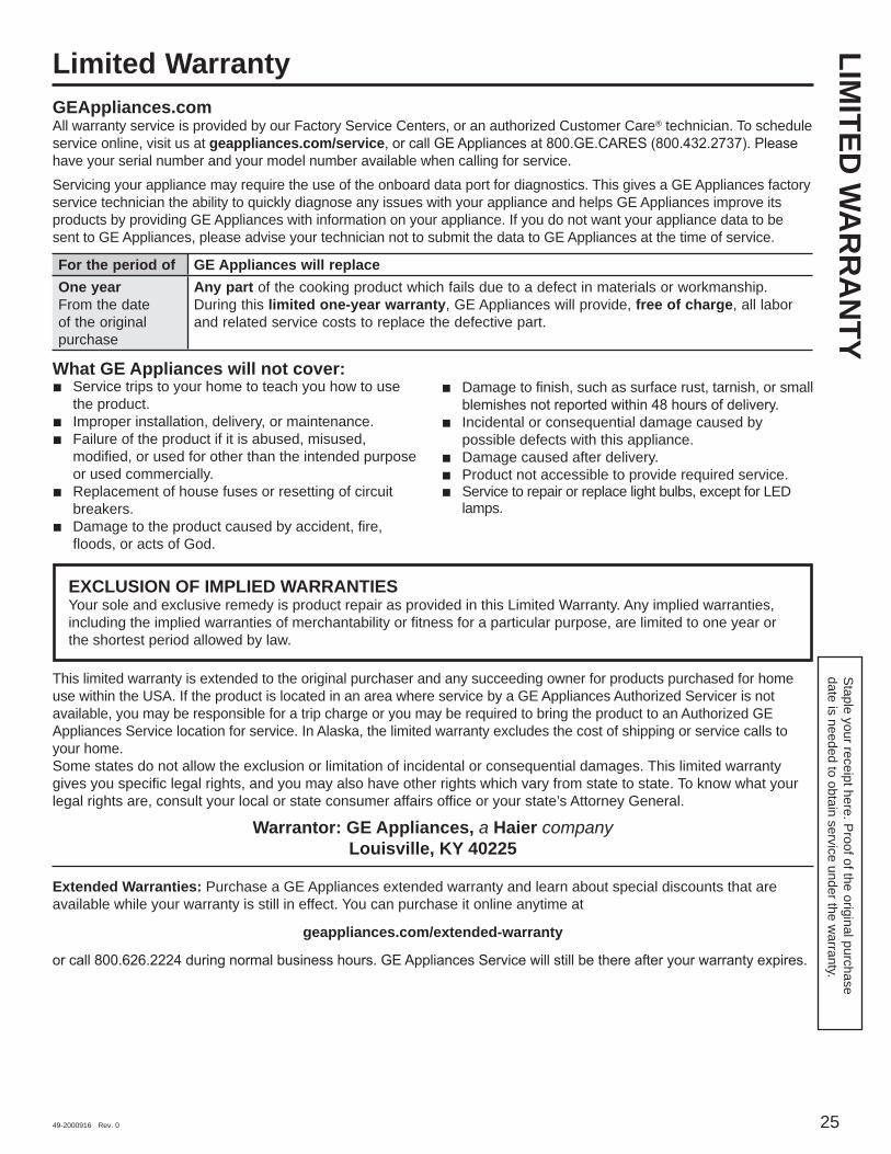
What GE Appliances will not cover: Service trips to your home to teach you how to use
the product. Improper installation, delivery, or maintenance. Failure of the product if it is abused, misused,
modified, or used for other than the intended purpose or used commercially.
Replacement of house fuses or resetting of circuit breakers.
Damage to the product caused by accident, fire, floods, or acts of God.
Damage to finish, such as surface rust, tarnish, or small
Incidental or consequential damage caused by possible defects with this appliance.
Damage caused after delivery. Product not accessible to provide required service. Service to repair or replace light bulbs, except for LED
lamps.
LIMITED
WA
RR
AN
TYLimited Warranty
EXCLUSION OF IMPLIED WARRANTIESYour sole and exclusive remedy is product repair as provided in this Limited Warranty. Any implied warranties, including the implied warranties of merchantability or fitness for a particular purpose, are limited to one year or the shortest period allowed by law.
This limited warranty is extended to the original purchaser and any succeeding owner for products purchased for home use within the USA. If the product is located in an area where service by a GE Appliances Authorized Servicer is not available, you may be responsible for a trip charge or you may be required to bring the product to an Authorized GE Appliances Service location for service. In Alaska, the limited warranty excludes the cost of shipping or service calls to your home.Some states do not allow the exclusion or limitation of incidental or consequential damages. This limited warranty gives you specific legal rights, and you may also have other rights which vary from state to state. To know what your legal rights are, consult your local or state consumer affairs office or your state’s Attorney General.
Warrantor: GE Appliances, a Haier company Louisville, KY 40225
Extended Warranties: Purchase a GE Appliances extended warranty and learn about special discounts that are available while your warranty is still in effect. You can purchase it online anytime at
geappliances.com/extended-warranty
For the period of GE Appliances will replaceOne year From the date of the original purchase
Any part of the cooking product which fails due to a defect in materials or workmanship. During this limited one-year warranty, GE Appliances will provide, free of charge, all labor and related service costs to replace the defective part.
26 49-2000916 Rev. 0
Printed in China
Consumer SupportC
ON
SUM
ER S
UPP
OR
T
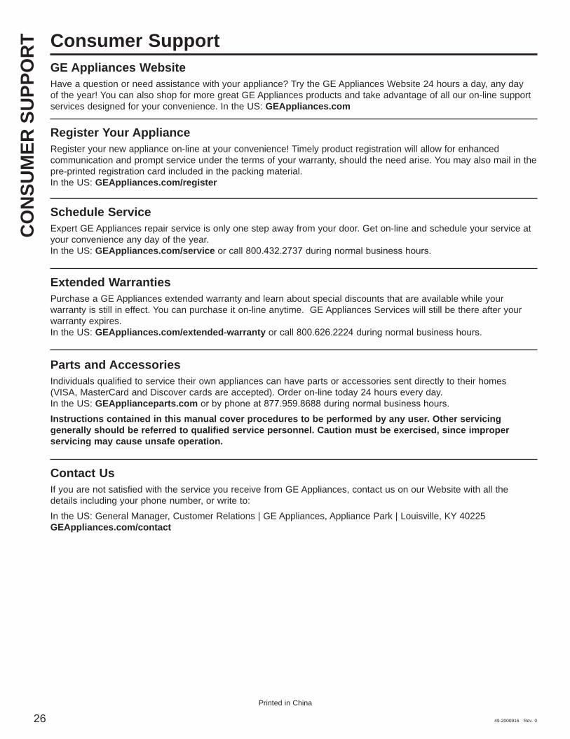
GE Appliances WebsiteHave a question or need assistance with your appliance? Try the GE Appliances Website 24 hours a day, any day of the year! You can also shop for more great GE Appliances products and take advantage of all our on-line support services designed for your convenience. In the US: GEAppliances.com
Register Your ApplianceRegister your new appliance on-line at your convenience! Timely product registration will allow for enhanced communication and prompt service under the terms of your warranty, should the need arise. You may also mail in the pre-printed registration card included in the packing material. In the US: GEAppliances.com/register
Schedule ServiceExpert GE Appliances repair service is only one step away from your door. Get on-line and schedule your service at your convenience any day of the year. In the US: GEAppliances.com/service
Extended WarrantiesPurchase a GE Appliances extended warranty and learn about special discounts that are available while your warranty is still in effect. You can purchase it on-line anytime. GE Appliances Services will still be there after your warranty expires. In the US: GEAppliances.com/extended-warranty
Parts and AccessoriesIndividuals qualified to service their own appliances can have parts or accessories sent directly to their homes (VISA, MasterCard and Discover cards are accepted). Order on-line today 24 hours every day. In the US: GEApplianceparts.comInstructions contained in this manual cover procedures to be performed by any user. Other servicing generally should be referred to qualified service personnel. Caution must be exercised, since improper servicing may cause unsafe operation.
Contact UsIf you are not satisfied with the service you receive from GE Appliances, contact us on our Website with all the details including your phone number, or write to:In the US: General Manager, Customer Relations | GE Appliances, Appliance Park | Louisville, KY 40225 GEAppliances.com/contact

49-2000916 Rev. 0 06-21
Escriba los números de modelo y de serie aquí:
Nº de Modelo ____________
Nº de Serie ______________
Usted puede encontrarlos en una etiqueta ubicada en la parte interna de la campana.
PV970PV976
CA
MPA
NA
S D
E V
ENTI
LAC
IÓN
D
E C
HIM
ENEA
INSTRUCCIONES DE SEGURIDAD . . . . . . . . . . . . . . . . . . . . 3
USO DE LA CAMPANAControles de la luz . . . . . . . . . . . . . . . . . . . . . . . 5Controles de la ventilación . . . . . . . . . . . . . . . . 5
CUIDADO Y LIMPIEZAFiltro de grasa . . . . . . . . . . . . . . . . . . . . . . . . . . . 6 Superficies de acero inoxidable . . . . . . . . . . . . 7 Luces LED . . . . . . . . . . . . . . . . . . . . . . . . . . . . . . 7
INSTRUCCIONES DE INSTALACIÓN . . . . . . . . . . . . . . . . . 8Preparación para la instalación . . . . . . . . . . . . 9 Ventilación hacia el exterior . . . . . . . . . . . . . . .14 Recirculación . . . . . . . . . . . . . . . . . . . . . . . . . . . .18
SOLUCIONAR PROBLEMAS . . . . . . 23
GARANTÍA LIMITADA . . . . . . . . . . . . . 25
SERVICIO AL CONSUMIDOR . . . . . 26
MANUAL DEL PROPIETARIO Y INSTALACIÓN

2 49-2000916 Rev. 0
GRACIAS POR HACER QUE GE APPLIANCES SEA PARTE DE SU HOGAR.
Ya sea que haya crecido usando GE Appliances, o que ésta es su primera vez, nos complace tenerlo en la familia.
Sentimos orgullo por el nivel de arte, innovación y diseño de cada uno de los electrodomésticos de GE Appliances, y creemos que usted también. Entre otras cosas, el registro de su electrodoméstico
asegura que podamos entregarle información importante del producto y detalles de la garantía cuando los necesite.
Registre su electrodoméstico GE ahora a través de Internet. Sitios Web y números telefónicos útiles están disponibles en la sección de Soporte para el Consumidor de este Manual del Propietario.
También puede enviar una carta en la tarjeta de inscripción preimpresa que se incluye con el material embalado.
49-2000916 Rev. 0 3
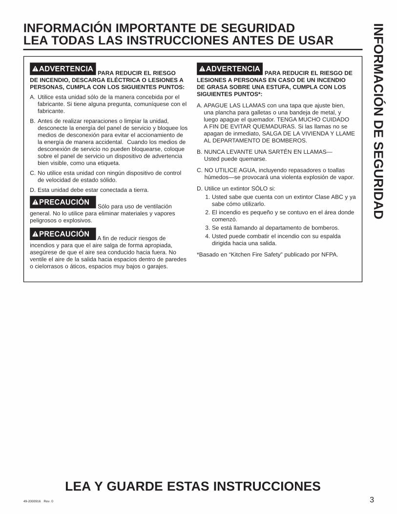
ADVERTENCIA PARA REDUCIR EL RIESGO DE INCENDIO, DESCARGA ELÉCTRICA O LESIONES A PERSONAS, CUMPLA CON LOS SIGUIENTES PUNTOS:A. Utilice esta unidad sólo de la manera concebida por el
fabricante. Si tiene alguna pregunta, comuníquese con el fabricante.
B. Antes de realizar reparaciones o limpiar la unidad, desconecte la energía del panel de servicio y bloquee los medios de desconexión para evitar el accionamiento de la energía de manera accidental. Cuando los medios de desconexión de servicio no pueden bloquearse, coloque sobre el panel de servicio un dispositivo de advertencia bien visible, como una etiqueta.
C. No utilice esta unidad con ningún dispositivo de control de velocidad de estado sólido.
D. Esta unidad debe estar conectada a tierra.
PRECAUCIÓN Sólo para uso de ventilación general. No lo utilice para eliminar materiales y vapores peligrosos o explosivos.
PRECAUCIÓN A fin de reducir riesgos de incendios y para que el aire salga de forma apropiada, asegúrese de que el aire sea conducido hacia fuera. No ventile el aire de la salida hacia espacios dentro de paredes o cielorrasos o áticos, espacios muy bajos o garajes.
ADVERTENCIA PARA REDUCIR EL RIESGO DE LESIONES A PERSONAS EN CASO DE UN INCENDIO DE GRASA SOBRE UNA ESTUFA, CUMPLA CON LOS SIGUIENTES PUNTOS*:
A. APAGUE LAS LLAMAS con una tapa que ajuste bien, una plancha para galletas o una bandeja de metal, y luego apague el quemador. TENGA MUCHO CUIDADO A FIN DE EVITAR QUEMADURAS. Si las llamas no se apagan de inmediato, SALGA DE LA VIVIENDA Y LLAME AL DEPARTAMENTO DE BOMBEROS.
B. NUNCA LEVANTE UNA SARTÉN EN LLAMAS— Usted puede quemarse.
C. NO UTILICE AGUA, incluyendo repasadores o toallas húmedos—se provocará una violenta explosión de vapor.
D. Utilice un extintor SÓLO si:1. Usted sabe que cuenta con un extintor Clase ABC y ya
sabe cómo utilizarlo.2. El incendio es pequeño y se contuvo en el área donde
comenzó.3. Se está llamando al departamento de bomberos.4. Usted puede combatir el incendio con su espalda
dirigida hacia una salida.
* Basado en “Kitchen Fire Safety” publicado por NFPA.
INFO
RM
AC
IÓN
DE SEG
UR
IDA
DINFORMACIÓN IMPORTANTE DE SEGURIDADLEA TODAS LAS INSTRUCCIONES ANTES DE USAR
LEA Y GUARDE ESTAS INSTRUCCIONES

4 49-2000916 Rev. 0
INFO
RM
AC
IÓN
DE
SEG
UR
IDA
D
READ AND SAVE THESE INSTRUCTIONS
INFORMACIÓN IMPORTANTE DE SEGURIDADLEA TODAS LAS INSTRUCCIONES ANTES DE USAR
ADVERTENCIA PARA REDUCIR EL RIESGO DE UN INCENDIO DE GRASA SOBRE UNA ESTUFA:A. Nunca deje unidades de superficie desatendidas en
configuraciones de calor elevadas. Los alimentos que hierven y se derraman provocan humo y derrames grasosos que pueden prenderse fuego. Caliente los aceites lentamente en configuraciones bajas o medias.
B. Siempre encienda (ON) la campana cuando cocine con configuraciones elevadas o cuando flambee alimentos (por ej., Crepes Suzette, cerezas Jubilee, carne flambeada a la pimienta en grano).
C. Limpie los ventiladores con frecuencia. No debe permitirse la acumulación de grasa en el ventilador o en el filtro.
D. Utilice el tamaño de recipiente adecuado. Siempre utilice recipientes de cocción apropiados para el tamaño del elemento de superficie.
ADVERTENCIA PARA REDUCIR EL RIESGO DE INCENDIO, DESCARGA ELÉCTRICA O LESIONES A PERSONAS, CUMPLA CON LOS SIGUIENTES PUNTOS:A. El trabajo de instalación y el cableado eléctrico deben
realizarlo personas calificadas en cumplimiento con todos los códigos y normas aplicables, incluyendo construcción con clasificación para incendios.
B. Se necesita suficiente aire para una combustión y escape de gases adecuados a través de la ventilación (chimenea) de equipamiento de combustión de combustible para evitar la contracorriente. Siga las pautas y normas de seguridad de fabricante del equipamiento de calefacción, tales como las publicadas por la Asociación Nacional de Protección contra Incendios (NFPA), la Sociedad Estadounidense de Ingenieros en Calefacción, Refrigeración y Aire Acondicionado (ASHRAE) y las autoridades de códigos locales. Cuando corresponda, instale un sistema de reposición (reemplazo) de aire de acuerdo con los requisitos del código local de construcción. Para acceder a soluciones de aire disponibles, visite GEAppliances.com.
C. Cuando realice cortes o perforaciones dentro de paredes o cielorrasos, no dañe el cableado eléctrico y otros servicios públicos ocultos.
D. Los sistemas de conductos siempre deben contar con una salida al exterior.
F. Desconecte el disyuntor de habitaciones adyacentes mientras esté trabajando.
ADVERTENCIA PARA REDUCIR EL RIESGO DE INCENDIO, SÓLO UTILICE CONDUCTOS DE METAL.
su campana a menos que esté específicamente recomendado en este manual. Cualquier otro servicio debe realizarlo un técnico calificado.

49-2000916 Rev. 0 5
ControlesU
SO D
E LA CA
MPA
NA
: Controles
3 2 1
1. MEMORY/OFF (memoria/apagado) Para configurar la memoria: A. Presione el botón MEMORY/OFF.
B. Ingrese las configuraciones deseadas de ventilación y de luz.
C. Presione el botón MEMORY/OFF de nuevo para guardar estas configuraciones.
Con sus configuraciones deseadas en la memoria, presione el botón MEMORY/OFF para restablecer los niveles de ventilación y de luz a sus configuraciones guardadas. Estas configuraciones permanecerán en la memoria hasta que se modifiquen u ocurra un corte de energía.s.
Para apagar la campana, presione el botón MEMORY/OFF.2. LIGHT (luz): Presione + o – para subir o bajar el nivel de
luz hasta la configuración deseada. Hay dos niveles de luz (LOW [bajo], HIGH [alto]) y OFF (apagado). Si continúa presionando los botones + o – , la luz se desplazará a través de las configuraciones.
3. AN (ventilador): Presione + o – para subir o bajar el nivel del ventilador hasta la configuración deseada. Hay 4 niveles de ventilación (LOW, MED [medio], HIGH, BOOST [impulso]) y OFF. Si continúa presionando los botones + o – , el ventilador se desplazará a través de las configuraciones.
NOTA: Puede oírse un pitido cada vez que se presiona un botón. Esto es normal.
NOTA: Los collarines ubicados alrededor de los botones se iluminan cuando se presionan los botones. Esto es normal. Los collarines se apagan en forma automática cuando se apaga la campana.
SENSOR DE CALOR: Esta campana cuenta con un sensor de calor que enciende el ventilador si se detectan temperaturas excesivas (más de 70
a su funcionamiento normal una vez que el sensor de calor
NOTA: Si la campana está OFF o en una velocidad de ventilación LOW, se detectan temperaturas por encima de 70
a la velocidad MED. Usted puede ajustar la velocidad de ventilación a HIGH o BOOST, pero no podrá ajustar la velocidad del ventilador a LOW o OFF hasta que se detecten
NOTA: Los collarines ubicados alrededor de los botones pueden no iluminarse si se activa el sensor de calor. Esto es normal.

6 49-2000916 Rev. 0
FiltrosC
UID
AD
O Y
LIM
PIEZ
A: F
iltro
s
Filtro de grasa metálicoEl filtro metálico atrapa la grasa liberada por los alimentos desde la estufa. El filtro también ayuda a evitar que las llamas (de los alimentos, grasa) dañen la parte interna de la campana. Por esta razón, el filtro debe estar SIEMPRE en su lugar cuando la campana esté en funcionamiento. El filtro de grasa es apto para lavavajillas y debe limpiarse cada 6 meses, o según sea necesario.
Para quitar: Tire hacia abajo la traba del filtro para liberarlo. Para volver a colocar:Coloque las lengüetas del extremo del filtro dentro de las ranuras del lado izquierdo de la abertura del filtro. Levante el lado derecho del filtro y presione ligeramente hasta que el filtro se trabe en su lugar. Verifique que la traba del filtro se encuentre en la posición cerrada para asegurar el filtro.Para limpiar el filtro, utilice agua jabonosa caliente y enjuague con agua limpia o lávelo en el lavavajillas. No utilice productos de limpieza abrasivos.NOTA: En el lavavajillas se producirá una leve decoloración.
Filtro de carbónSólo para instalación con recirculaciónSi el modelo no tiene ventilación al exterior, el aire se recirculará a través de un filtro de carbón desechable que ayuda a remover humo y olores.El filtro de carbón debe cambiarse cuando esté evidentemente sucio o decolorado (usualmente después de 6 a 12 meses, dependiendo del uso de la campana).NOTA: NO enjuague o coloque el filtro de carbón en el lavavajillas automático.El filtro de carbón no puede limpiarse. Debe cambiarse.
Para consultar sobre la compra de filtros de carbón de repuesto o para encontrar la ubicación del distribuidor más cercano a su domicilio, llame a nuestro número gratuito:
Para quitar:1. Quite el filtro metálico—ver la sección Filtro de grasa
metálico.2. Quite el filtro de carbón presionando sobre las dos manijas
de las lengüetas de bloqueo.Para volver a colocar:1. Introduzca el filtro de carbón dentro de la abertura. Presione
las manijas de las lengüetas de bloqueo hacia el centro y libérelas para sujetar las lengüetas de bloqueo.
2. Vuelva a colocar el filtro metálico—ver la sección Filtro de grasa metálico.
Asegúrese de que el disyuntor esté apagado y que todas las superficies estén frías antes de limpiar o de realizar el servicio técnico de cualquier pieza de la campana de ventilación.
Manija de la lengüeta de bloqueo
Manija de la lengüeta de bloqueo
49-2000916 Rev. 0 7
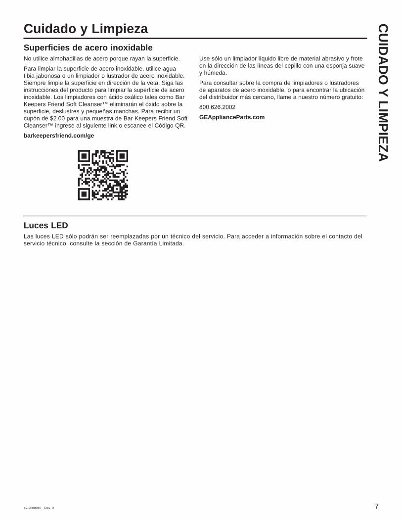
Cuidado y LimpiezaSuperficies de acero inoxidableNo utilice almohadillas de acero porque rayan la superficie.Para limpiar la superficie de acero inoxidable, utilice agua tibia jabonosa o un limpiador o lustrador de acero inoxidable. Siempre limpie la superficie en dirección de la veta. Siga las instrucciones del producto para limpiar la superficie de acero inoxidable. Los limpiadores con ácido oxálico tales como Bar Keepers Friend Soft Cleanser™ eliminarán el óxido sobre la superficie, deslustres y pequeñas manchas. Para recibir un cupón de $2.00 para una muestra de Bar Keepers Friend Soft Cleanser™ ingrese al siguiente link o escanee el Código QR.barkeepersfriend.com/ge
Use sólo un limpiador líquido libre de material abrasivo y frote en la dirección de las líneas del cepillo con una esponja suave y húmeda. Para consultar sobre la compra de limpiadores o lustradores de aparatos de acero inoxidable, o para encontrar la ubicación del distribuidor más cercano, llame a nuestro número gratuito:
GEApplianceParts.com
CU
IDA
DO
Y LIMPIEZA
Luces LEDLas luces LED sólo podrán ser reemplazadas por un técnico del servicio. Para acceder a información sobre el contacto del servicio técnico, consulte la sección de Garantía Limitada.

49-2000916 Rev. 0
Instrucciones de instalación
DIMENSIONES DEL PRODUCTO
Campanas de ventilación de chimenea
INST
RU
CC
ION
ES D
E IN
STA
LAC
IÓN
Los modelos de 30” requieren una abertura de 30” de ancho
”
*Altura hasta el
cielorraso
”29
10-7
13-1
2- ”
*Altura hasta el cielorrasoVentilación Recirculación
MinMax
Los modelos de 36” requieren una abertura de 36” de ancho
* Para las alturas del cielorraso de las cubiertas del conducto provistas para instalación ventilada e instalación con recirculación, consulte la tabla de la página 13.
Deje 1” de superposición para el conducto.
*Altura hasta el cielorraso
Ventilación Recirculación
Min
Max*Height to
Ceiling
¿Preguntas? Llame al 800.GE.CARES (800.432.2737) o visite nuestro sitio Web en: GEAppliances.com
ANTES DE COMENZARLea estas instrucciones por completo y con detenimiento.
IMPORTANTE – Guarde estas instrucciones para el uso de inspectores locales.
IMPORTANTE – Cumpla con todos los códigos y ordenanzas vigentes. Nota al instalador – Asegúrese de dejar estas instrucciones con el Consumidor.Nota al consumidor – Conserve estas instrucciones para referencia futura.Nivel de capacidad – La instalación de esta campana de ventilación requiere capacidades mecánicas y eléctricas básicas.Tiempo de finalización – Aproximadamente de 1 a 3 horas.
instalación adecuada.
una instalación incorrecta.
PRECAUCIÓN Debido al peso y tamaño de estas campanas de ventilación y para reducir el riesgo de lesiones personales o daños al producto, SE NECESITAN DOS PERSONAS PARA REALIZAR UNA INSTALACIÓN CORRECTA.
PARA SU SEGURIDAD:
ADVERTENCIA Antes de comenzar la instalación, desconecte la energía del panel de servicio y bloquee los medios de desconexión para evitar el accionamiento de la energía de manera accidental. Cuando los medios de desconexión de servicio no pueden bloquearse, coloque sobre el panel de servicio un dispositivo de advertencia bien visible, como una etiqueta.
49-2000916 Rev. 0 9
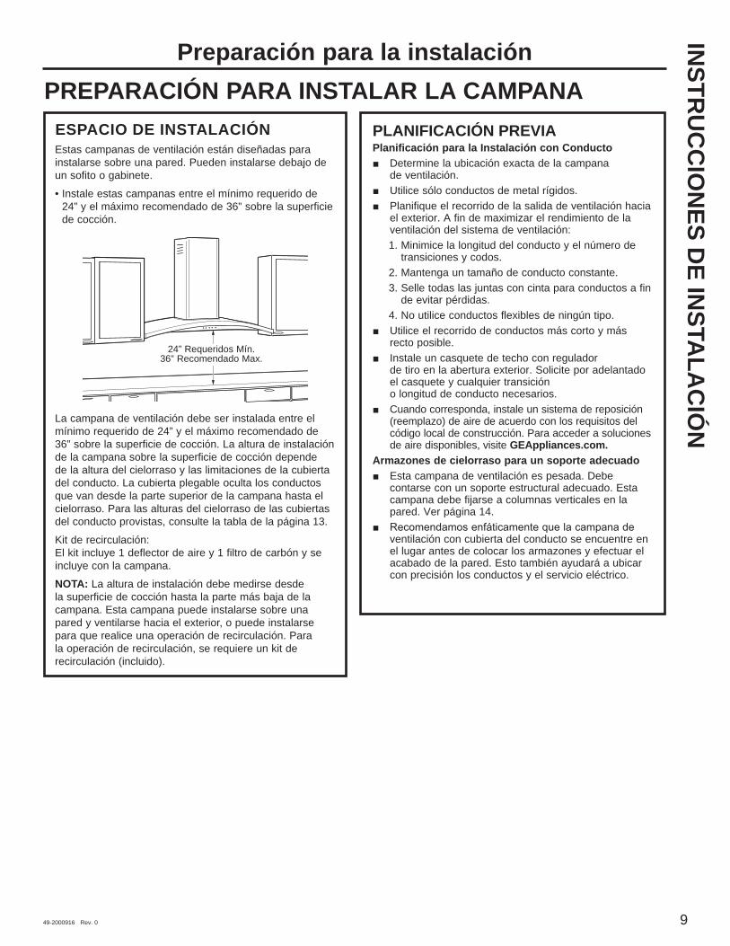
ESPACIO DE INSTALACIÓN Estas campanas de ventilación están diseñadas para instalarse sobre una pared. Pueden instalarse debajo de un sofito o gabinete.• Instale estas campanas entre el mínimo requerido de
24” y el máximo recomendado de 36” sobre la superficie de cocción.
La campana de ventilación debe ser instalada entre el mínimo requerido de 24” y el máximo recomendado de 36” sobre la superficie de cocción. La altura de instalación de la campana sobre la superficie de cocción depende de la altura del cielorraso y las limitaciones de la cubierta del conducto. La cubierta plegable oculta los conductos que van desde la parte superior de la campana hasta el cielorraso. Para las alturas del cielorraso de las cubiertas del conducto provistas, consulte la tabla de la página 13.Kit de recirculación: El kit incluye 1 deflector de aire y 1 filtro de carbón y se incluye con la campana.NOTA: La altura de instalación debe medirse desde la superficie de cocción hasta la parte más baja de la campana. Esta campana puede instalarse sobre una pared y ventilarse hacia el exterior, o puede instalarse para que realice una operación de recirculación. Para la operación de recirculación, se requiere un kit de recirculación (incluido).
INSTR
UC
CIO
NES D
E INSTA
LAC
IÓN
Preparación para la instalaciónPREPARACIÓN PARA INSTALAR LA CAMPANA
PLANIFICACIÓN PREVIAPlanificación para la Instalación con Conducto
Determine la ubicación exacta de la campana de ventilación.
Utilice sólo conductos de metal rígidos. Planifique el recorrido de la salida de ventilación hacia
el exterior. A fin de maximizar el rendimiento de la ventilación del sistema de ventilación:1. Minimice la longitud del conducto y el número de
transiciones y codos.2. Mantenga un tamaño de conducto constante.3. Selle todas las juntas con cinta para conductos a fin
de evitar pérdidas.4. No utilice conductos flexibles de ningún tipo.
Utilice el recorrido de conductos más corto y más recto posible.
Instale un casquete de techo con regulador de tiro en la abertura exterior. Solicite por adelantado el casquete y cualquier transición o longitud de conducto necesarios.
Cuando corresponda, instale un sistema de reposición (reemplazo) de aire de acuerdo con los requisitos del código local de construcción. Para acceder a soluciones de aire disponibles, visite GEAppliances.com.
Armazones de cielorraso para un soporte adecuado Esta campana de ventilación es pesada. Debe
contarse con un soporte estructural adecuado. Esta campana debe fijarse a columnas verticales en la pared. Ver página 14.
ventilación con cubierta del conducto se encuentre en el lugar antes de colocar los armazones y efectuar el acabado de la pared. Esto también ayudará a ubicar con precisión los conductos y el servicio eléctrico.
24” Requeridos Mín.36” Recomendado Max.

10 49-2000916 Rev. 0
Preparación para la instalaciónIN
STR
UC
CIO
NES
DE
INST
ALA
CIÓ
N
SUMINISTRO DE ENERGÍAIMPORTANTE – (Tenga a bien leer cuidadosamente)
ADVERTENCIA PARA SEGURIDAD PERSONAL, ESTE APARATO DEBE CONECTARSE A TIERRA DE MANERA ADECUADA.Quite el fusible o abra el interruptor de circuitos antes de comenzar la instalación. No utilice un cable de extensión o un enchufe adaptador con este artefacto. Siga los Códigos Eléctricos Nacionales o códigos y ordenanzas locales vigentes.Suministro eléctricoEstas campanas de ventilación deben contar con un suministro de 120V, 60Hz, deben estar conectadas a un circuito derivado individual con una adecuada conexión a tierra y deben contar con la protección de un interruptor de circuitos o un fusible con retraso de 15 o 20 amperios.
El cableado debe ser de 2 hilos con conexión a tierra.
Si el suministro eléctrico no cumple con los requisitos anteriores, llame a un electricista con licencia antes de continuar.
Dirija el cableado doméstico lo más cerca posible a la ubicación de la instalación, en el cielorraso o pared trasera. Ver página 14 para más detalles.
Conecte el cableado al cableado doméstico en cumplimiento con los códigos locales.
Instrucciones de conexión a tierraEl conductor a tierra debe conectarse a un metal con conexión a tierra, un sistema de cableado permanente o una terminal o conductor de conexión a tierra del equipamiento en la campana.
ADVERTENCIA Una conexión inadecuada del conductor de conexión a tierra del equipamiento puede provocar un riesgo de descarga eléctrica. Consulte a un electricista calificado o representante de servicio técnico si tiene dudas sobre la correcta conexión a tierra del artefacto.
Esta campana debe usar un conducto redondo de 8”. Puede conectarse a un
conducto de 3-1/4” x 12”.NO USE conductos flexibles de plástico.NOTA: Cualquier sistema de ventilación doméstico, como una campana de ventilación, puede interrumpir el flujo adecuado de aire de combustión y de escape requerido para chimeneas, hornos a gas, calentadores de agua a gas y otros sistemas de ventilación natural. Para minimizar las posibilidades de interrupción de tales sistemas de ventilación natural, siga las pautas y normas de seguridad del fabricante del equipamiento de calefacción, tales como las publicadas por NFPA y ASHRAE. Cuando corresponda, instale un sistema de reposición (reemplazo) de aire de acuerdo con los requisitos del código local de construcción. Para acceder a soluciones de aire disponibles, visite GEAppliances.com.
49-2000916 Rev. 0 11
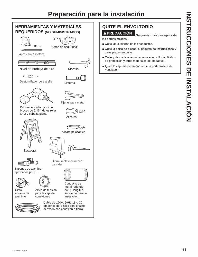
QUITE EL ENVOLTORIOPRECAUCIÓN Se guantes para protegerse de
los bordes afilados.
otras piezas en cajas.
de protección y otros materiales de empaque.
Quite la espuma de empaque de la parte trasera del ventilador.
INSTR
UC
CIO
NES D
E INSTA
LAC
IÓN
Preparación para la instalación
HERRAMIENTAS Y MATERIALES REQUERIDOS (NO SUMINISTRADOS)
Alicates
Alicate pelacables
Tijeras para metal
Nivel de burbuja de aire
Cinta aislante de aluminio
Gafas de seguridad
Cable de 120V, 60Hz 15 o 20 amperios de 2 hilos con circuito derivado con conexión a tierra
Escalera
Sierra sable o serrucho de calar
Destornillador de estrella
Alivio de tensión para la caja de conexiones
Conducto de metal redondo
suficiente para la instalación
Martillo
Perforadora eléctrica con
N° 2 y cabeza plana
Linterna
Tapones de alambre aprobados por UL
Lápiz y cinta métrica
12 49-2000916 Rev. 0
Preparación para la instalación
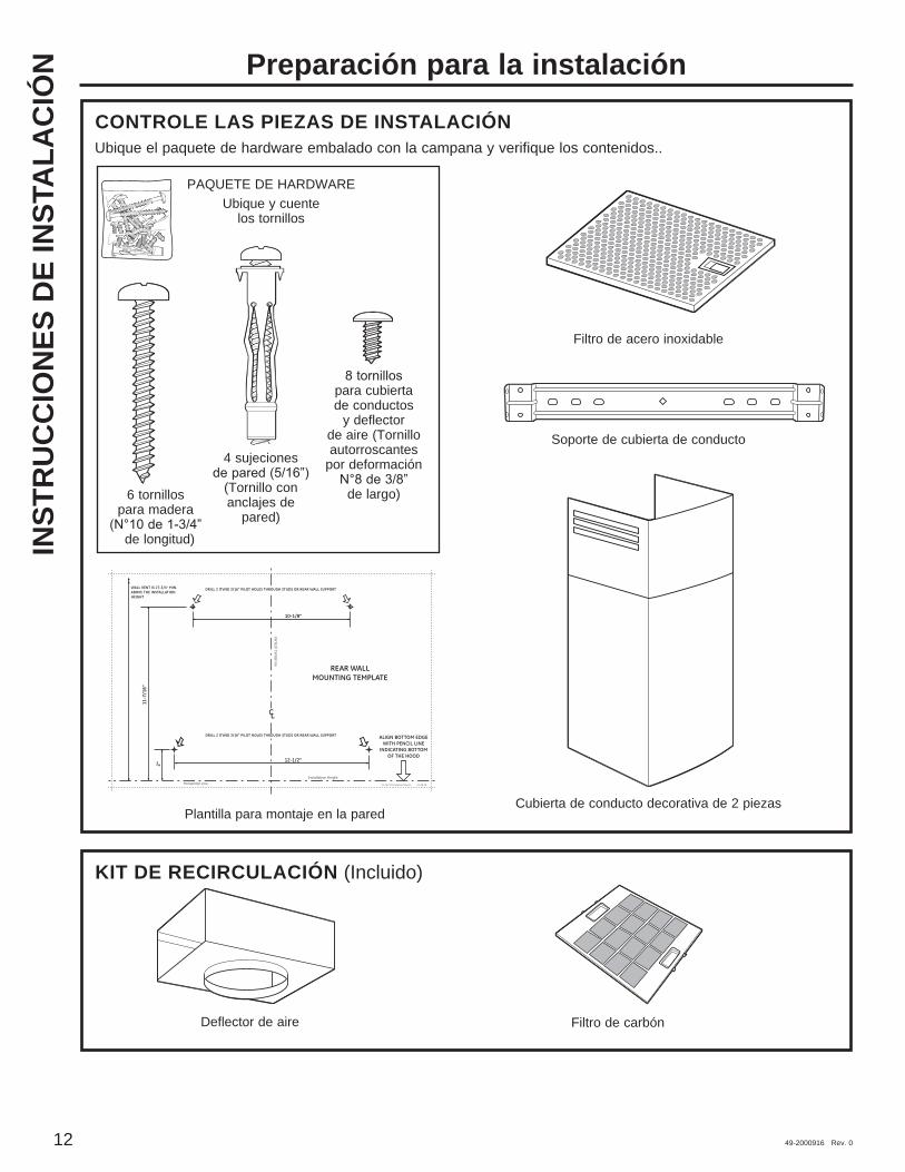
CONTROLE LAS PIEZAS DE INSTALACIÓNUbique el paquete de hardware embalado con la campana y verifique los contenidos..
KIT DE RECIRCULACIÓN (Incluido)
Deflector de aire Filtro de carbón
Plantilla para montaje en la pared
Filtro de acero inoxidable
INST
RU
CC
ION
ES D
E IN
STA
LAC
IÓN
REAR WALLMOUNTING TEMPLATE
VerticalCenterline
ALIGN BOTTOM EDGEWITH PENCIL LINE
INDICATING BOTTOMOF THE HOOD
11-7
/16"
Installation HeightHorizontal Line
CL
DRILL 2 (TWO) 3/16" PILOT HOLES THROUGH STUDS OR REAR WALL SUPPORT
10-1/8"
12-08 JR
2"
DRILL 2 (TWO) 3/16" PILOT HOLES THROUGH STUDS OR REAR WALL SUPPORT
12-1/2"
WALL VENT IS 27-3/4" MIN.ABOVE THE INSTALLATIONHEIGHT
31-14772 Printed in Mexico
PAQUETE DE HARDWAREUbique y cuente
los tornillos
6 tornillos para madera
de longitud)
4 sujeciones
(Tornillo con anclajes de
pared)
para cubierta de conductos
y deflector de aire (Tornillo autorroscantes
por deformación
de largo)
Soporte de cubierta de conducto
Cubierta de conducto decorativa de 2 piezas
49-2000916 Rev. 0 13
INSTR
UC
CIO
NES D
E INSTA
LAC
IÓN
Preparación para la instalación
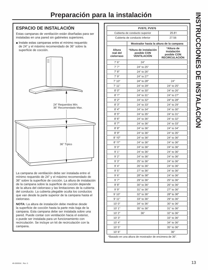
ESPACIO DE INSTALACIÓNEstas campanas de ventilación están diseñadas para ser instaladas en una pared sin gabinetes superiores.
de 24” y el máximo recomendado de 36” sobre la superficie de cocción.
La campana de ventilación debe ser instalada entre el mínimo requerido de 24” y el máximo recomendado de 36” sobre la superficie de cocción. La altura de instalación de la campana sobre la superficie de cocción depende de la altura del cielorraso y las limitaciones de la cubierta del conducto. La cubierta plegable oculta los conductos que van desde la parte superior de la campana hasta el cielorraso.NOTA: La altura de instalación debe medirse desde la superficie de cocción hasta la parte más baja de la campana. Esta campana debe ser instalada sobre una pared. Puede contar con ventilación hacia el exterior, o puede ser instalada para un funcionamiento con recirculación. Se incluye un kit de recirculación con la campana.
24” Requeridos Mín.36” Recomendado Max.
36” Típico
PV970, PV976Cubierta de conducto superior
Cubierta de conducto inferior 27.56
Mostrador hasta la altura de la campana
Altura real del
cielorraso
*Altura de instalación posible CON
VENTILACIÓN
*Altura de instalación
posible CON RECIRCULACIÓN
7' 6" 24"
7' 7" 24" to 25"
24" to 26"
7' 9" 24" to 27"
7' 10" 24"
7' 11" 24" to 29" 24" to 25"
24" to 30" 24" to 26"
24" to 31" 24" to 27"
24" to 32"
24" to 33" 24" to 29"
24" to 34" 24" to 30"
24" to 35" 24" to 31"
24" to 36" 24" to 32"
24" to 36" 24" to 33"
24" to 36" 24" to 34"
24" to 36" 24" to 35"
24" to 36" 24" to 36"
24" to 36" 24" to 36"
9' 0" 24" to 36" 24" to 36"
9' 1" 24" to 36" 24" to 36"
9' 2" 24" to 36" 24" to 36"
9' 3" 25" to 36" 24" to 36"
9' 4" 26" to 36" 24" to 36"
9' 5" 27" to 36" 24" to 36"
9' 6" 24" to 36"
9' 7" 29" to 36" 25" to 36"
30" to 36" 26" to 36"
9' 9" 31" to 36" 27" to 36"
9' 10" 32" to 36"
9' 11" 33" to 36" 29" to 36"
10' 0" 34" to 36" 30" to 36"
10' 1" 35" to 36" 31" to 36"
10' 2" 36" 32" to 36"
10' 3" 33" to 36"
10' 4" 34" to 36"
10' 5" 35" to 36"
10' 6" 36"
*Basado en una altura de mostrador de encimera de 36”.

14 49-2000916 Rev. 0
UBICACIONES DE LOS CONDUCTOS Y CABLEADO
Determine la ubicación exacta de la campana de ventilación.
Ubique la plantilla embalada con las instrucciones. - Mida desde el piso hasta el extremo superior de
la superficie de cocción. Agregue la altura de instalación de la campana determinada en las
- Utilice un nivel para dibujar una línea recta en lápiz sobre la pared.
- Adhiera con cinta la plantilla en su posición a lo largo de la línea de lápiz. ASEGÚRESE DE QUE LA PLANTILLA ESTÉ NIVELADA.
Conductos en el cielorraso:Si el conducto se ventilará directamente hacia el cielorraso:
Utilice un nivel para dibujar una línea hacia arriba, desde la línea central de la plantilla hasta el cielorraso.
Mida 5” desde la pared trasera hasta la línea central de
NOTA: Si no hay paredes de construcción en seco, agregue el espesor de las mismas a la dimensión de 5”.Conductos en la pared:Si el conducto se ventilará hacia la parte trasera:
Utilice un nivel para dibujar una línea hacia arriba, desde la línea central de la plantilla.
indica la altura de instalación inferior, hasta la línea
(El orificio puede ser alargado para un codo de conducto.) UBICACIÓN DEL CABLEADO DOMÉSTICO:
La caja de conexiones se encuentra en el lado superior izquierdo de la campana.
El cableado debe ingresar por la pared trasera por lo
y dentro de 5” del lado izquierdo de la línea central.
PASO 1: INSTALE EL ARMAZÓN PARA EL SOPORTE DE LA CAMPANA
IMPORTANTE: El armazón debe poder soportar 100 lbs.
Si se cuenta con paredes de construcción en seco, marque las ubicaciones de los orificios para tornillos para los soportes de montaje superiores. Quite la plantilla.
Corte suficiente pared de construcción en seco para exponer 2 columnas verticales en la ubicación de soporte indicada en la plantilla.
Instale un soporte horizontal por lo menos 1” x 12” entre dos columnas de pared en la ubicación de tornillo de montaje. El soporte horizontal debe encontrarse alineado con el lado de la habitación de las columnas. Utilice listones detrás de ambos lados del soporte para sujetar a las columnas de pared.
NOTA: Se necesitarán 2 soportes horizontales si hay una columna ubicada entre las ubicaciones de tornillo horizontal (ver figura).IMPORTANTE: Vuelva a instalar la pared de construcción en seco para lograr una superficie de montaje pareja.
REAR WALLMOUNTING TEMPLATE
VerticalCenterline
ALIGN BOTTOM EDGEWITH PENCIL LINE
INDICATING BOTTOMOF THE HOOD
11-7
/16"
Installation HeightHorizontal Line
CL
DRILL 2 (TWO) 3/16" PILOT HOLES THROUGH STUDS OR REAR WALL SUPPORT
10-1/8"
12-08 JR
2"
DRILL 2 (TWO) 3/16" PILOT HOLES THROUGH STUDS OR REAR WALL SUPPORT
12-1/2"
WALL VENT IS 27-3/4" MIN.ABOVE THE INSTALLATIONHEIGHT
31-14772 Printed in Mexico
Cielorraso
Ubicación del cableado doméstico CL
5”
Min.
Ventilación de pared
sobre la altura de
instalación
5” de la línea central a la
pared
Visión desde los listones traseros
Soporte de montaje mínimo
de 1” x 12”
Línea central del espacio
de instalación
Instrucciones de InstalaciónIN
STR
UC
CIO
NES
DE
INST
ALA
CIÓ
N
INSTALACIÓN - VENTILACIÓN HACIA EL EXTERIOR
49-2000916 Rev. 0 15
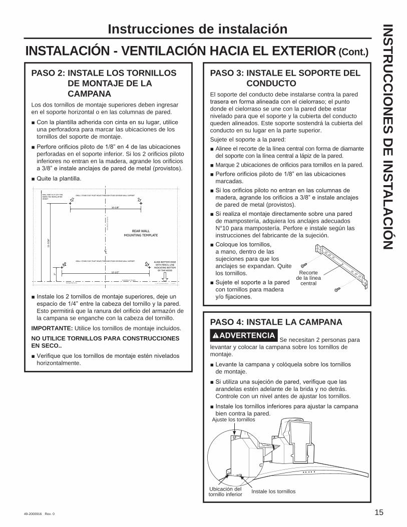
PASO 2: INSTALE LOS TORNILLOS DE MONTAJE DE LA CAMPANA
Los dos tornillos de montaje superiores deben ingresar en el soporte horizontal o en las columnas de pared.
una perforadora para marcar las ubicaciones de los tornillos del soporte de montaje.
perforadas en el soporte inferior. Si los 2 orificios piloto inferiores no entran en la madera, agrande los orificios
Esto permitirá que la ranura del orificio del armazón de la campana se enganche con la cabeza del tornillo.
IMPORTANTE: Utilice los tornillos de montaje incluidos.NO UTILICE TORNILLOS PARA CONSTRUCCIONES EN SECO..
horizontalmente.
PASO 3: INSTALE EL SOPORTE DEL CONDUCTO
El soporte del conducto debe instalarse contra la pared
donde el cielorraso se une con la pared debe estar nivelado para que el soporte y la cubierta del conducto queden alineados. Este soporte sostendrá la cubierta del conducto en su lugar en la parte superior.Sujete el soporte a la pared:
Alinee el recorte de la línea central con forma de diamante del soporte con la línea central a lápiz de la pared.Marque 2 ubicaciones de orificios para tornillos en la pared.
marcadas.
de pared de metal (provistos).
de mampostería, adquiera los anclajes adecuados N°10 para mampostería. Perfore e instale según las instrucciones del fabricante de la sujeción.
a mano, dentro de las sujeciones para que los anclajes se expandan. Quite los tornillos.
con tornillos para madera
PASO 4: INSTALE LA CAMPANAADVERTENCIA Se necesitan 2 personas para
levantar y colocar la campana sobre los tornillos de montaje.
de montaje.
arandelas estén adelante de la brida y no detrás. Controle con un nivel antes de ajustar los tornillos.
bien contra la pared.
REAR WALLMOUNTING TEMPLATE
VerticalCenterline
ALIGN BOTTOM EDGEWITH PENCIL LINE
INDICATING BOTTOMOF THE HOOD
11-7
/16"
Installation HeightHorizontal Line
CL
DRILL 2 (TWO) 3/16" PILOT HOLES THROUGH STUDS OR REAR WALL SUPPORT
10-1/8"
12-08 JR
2"
DRILL 2 (TWO) 3/16" PILOT HOLES THROUGH STUDS OR REAR WALL SUPPORT
12-1/2"
WALL VENT IS 27-3/4" MIN.ABOVE THE INSTALLATIONHEIGHT
31-14772 Printed in Mexico
Recorte de la línea
central
Ajuste los tornillos
Instale los tornillosUbicación del tornillo inferior
Instrucciones de instalaciónINSTALACIÓN - VENTILACIÓN HACIA EL EXTERIOR (Cont.)
INSTR
UC
CIO
NES D
E INSTA
LAC
IÓN

16 49-2000916 Rev. 0
PASO 5: CONECTE LOS CONDUCTOS Quite la cinta de embalaje del regulador de tiro. Instale el conducto, realizando conexiones en la dirección del flujo de aire, como se ilustra.
Presione el conducto sobre la salida de escape y el regulador de tiro.
Ajuste las juntas del conducto con tornillos para placas de metal.
Envuelva todas las juntas del conducto y las conexiones de la brida con cinta aislante de aluminio para un sellado hermético.
PRECAUCIÓN No use tornillos para placas de metal en la conexión de la brida de la campana. Si lo hace no funcionará bien el regulador de tiro. Selle la conexión sólo con cinta aislante.
PASO 6: CONECTE LOS ELEMENTOS ELÉCTRICOS
Verifique que la energía esté cortada en la fuente.
ADVERTENCIA Si el cableado doméstico no cuenta con un cable de 2 hilos con conexión a tierra, un instalador debe realizar una conexión a tierra. Cuando el cableado doméstico es de aluminio, asegúrese de usar un compuesto antioxidante y conectores de aluminio a cobre aprobados por UL.
Quite los 6 tornillos de la tapa de la caja de conexiones y el calado sobre la parte superior izquierda.
PASO 6: CONECTE LOS ELEMENTOS ELÉCTRICOS (cont.)
de conexiones con un alivio de tensión (no provisto).
derivado.
derivado.
circuito derivado o al cable de conexión a tierra.
sobre cada conector eléctrico.
vuelva a colocar la tapa. Verifique que los cables no sufran pellizcos.
6 tornillos originales.
Coloque cinta aislante
sobre las juntas
y tornillo
Tornillo
Flujo de aire
Tapa de la caja
de conexiones
Calado
Instrucciones de instalaciónINSTALACIÓN - VENTILACIÓN HACIA EL EXTERIOR (Cont.)
INST
RU
CC
ION
ES D
E IN
STA
LAC
IÓN
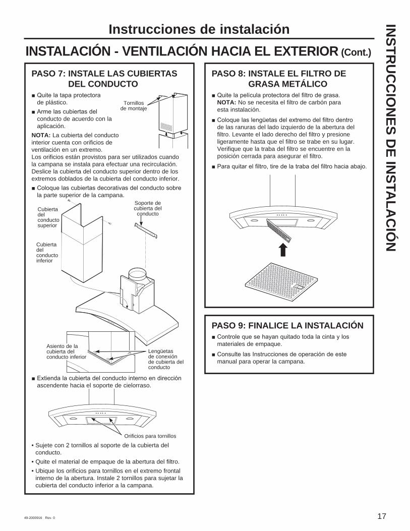
49-2000916 Rev. 0 17
PASO 7: INSTALE LAS CUBIERTAS DEL CONDUCTO
de plástico.
conducto de acuerdo con la aplicación.
NOTA: La cubierta del conducto interior cuenta con orificios de ventilación en un extremo. Los orificios están provistos para ser utilizados cuando la campana se instala para efectuar una recirculación. Deslice la cubierta del conducto superior dentro de los extremos doblados de la cubierta del conducto inferior.
la parte superior de la campana.
ascendente hacia el soporte de cielorraso.
• Sujete con 2 tornillos al soporte de la cubierta del conducto.
• Quite el material de empaque de la abertura del filtro.• Ubique los orificios para tornillos en el extremo frontal
interno de la abertura. Instale 2 tornillos para sujetar la cubierta del conducto inferior a la campana.
PASO 8: INSTALE EL FILTRO DE GRASA METÁLICO
NOTA: No se necesita el filtro de carbón para esta instalación.
de las ranuras del lado izquierdo de la abertura del filtro. Levante el lado derecho del filtro y presione ligeramente hasta que el filtro se trabe en su lugar. Verifique que la traba del filtro se encuentre en la posición cerrada para asegurar el filtro.
PASO 9: FINALICE LA INSTALACIÓN
materiales de empaque.
manual para operar la campana.
Tornillos de montaje
Asiento de la cubierta del conducto inferior
Soporte de cubierta del
conducto
Cubierta del conducto inferior
Cubierta del conducto superior
Lengüetas de conexión de cubierta del conducto
Orificios para tornillos
Instrucciones de instalaciónINSTALACIÓN - VENTILACIÓN HACIA EL EXTERIOR (Cont.)
INSTR
UC
CIO
NES D
E INSTA
LAC
IÓN

49-2000916 Rev. 0
UBICACIONES DE LOS CONDUCTOS Y CABLEADO
de ventilación.
de la superficie de cocción. Agregue la altura de instalación de la campana determinada en las
largo de la línea de lápiz. ASEGÚRESE DE QUE LA PLANTILLA ESTÉ NIVELADA.
desde la línea central de la plantilla hasta el cielorraso.
UBICACIÓN DEL CABLEADO DOMÉSTICO:
izquierdo de la campana.
de la campana, y dentro de 5” de la línea central.
PASO 1: INSTALE EL ARMAZÓN PARA EL SOPORTE DE LA CAMPANA
IMPORTANTE: El armazón debe poder soportar 100 lbs.
Si se cuenta con paredes de construcción en seco, marque las ubicaciones de los orificios para tornillos para los soportes de montaje superiores. Quite la plantilla.
exponer 2 columnas verticales en la ubicación del soporte indicada en la plantilla.
12” entre dos columnas de pared en la ubicación del tornillo de montaje. El soporte horizontal debe encontrarse alineado con el lado de la habitación de las columnas. Utilice listones detrás de ambos lados del soporte para sujetar a las columnas de pared.
NOTA: Se necesitarán 2 soportes horizontales si hay una columna ubicada entre las ubicaciones de tornillo horizontal (ver figura).IMPORTANTE: Vuelva a instalar la pared de construcción en seco para lograr una superficie de montaje pareja.
REAR WALLMOUNTING TEMPLATE
VerticalCenterline
ALIGN BOTTOM EDGEWITH PENCIL LINE
INDICATING BOTTOMOF THE HOOD
11-7
/16"
Installation HeightHorizontal Line
CL
DRILL 2 (TWO) 3/16" PILOT HOLES THROUGH STUDS OR REAR WALL SUPPORT
10-1/8"
12-08 JR
2"
DRILL 2 (TWO) 3/16" PILOT HOLES THROUGH STUDS OR REAR WALL SUPPORT
12-1/2"
WALL VENT IS 27-3/4" MIN.ABOVE THE INSTALLATIONHEIGHT
31-14772 Printed in Mexico
CielorrasoUbicación del cableado
doméstico CL
5”
Min.
5” de la línea central a la pared
Visión desde los listones traseros
Soporte de montaje mínimo
de 1” x 12”
Línea central del espacio
de instalación
Instrucciones de instalaciónINSTALACIÓN - RECIRCULACIÓN
INST
RU
CC
ION
ES D
E IN
STA
LAC
IÓN
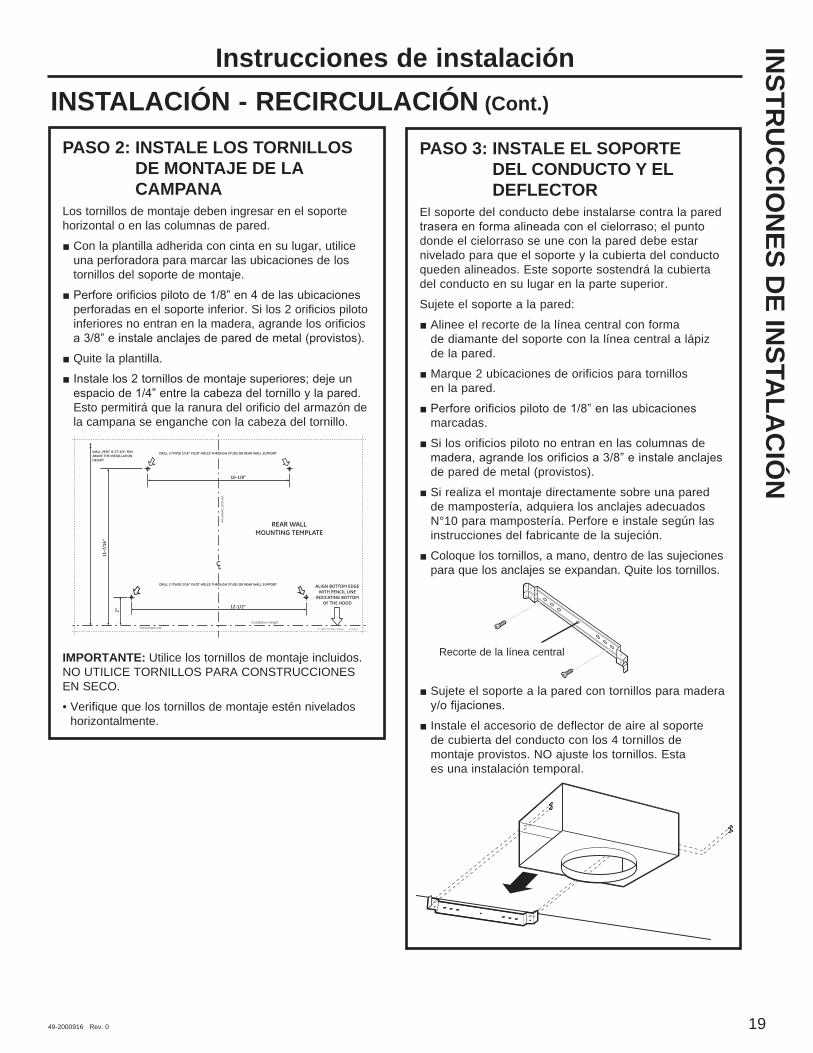
49-2000916 Rev. 0 19
INSTALACIÓN - RECIRCULACIÓN (Cont.)
PASO 2: INSTALE LOS TORNILLOS DE MONTAJE DE LA CAMPANA
Los tornillos de montaje deben ingresar en el soporte horizontal o en las columnas de pared.
Con la plantilla adherida con cinta en su lugar, utilice una perforadora para marcar las ubicaciones de los tornillos del soporte de montaje.
perforadas en el soporte inferior. Si los 2 orificios piloto inferiores no entran en la madera, agrande los orificios
Quite la plantilla.
Esto permitirá que la ranura del orificio del armazón de la campana se enganche con la cabeza del tornillo.
IMPORTANTE: Utilice los tornillos de montaje incluidos. NO UTILICE TORNILLOS PARA CONSTRUCCIONES EN SECO.• Verifique que los tornillos de montaje estén nivelados
horizontalmente.
PASO 3: INSTALE EL SOPORTE DEL CONDUCTO Y EL DEFLECTOR
El soporte del conducto debe instalarse contra la pared
donde el cielorraso se une con la pared debe estar nivelado para que el soporte y la cubierta del conducto queden alineados. Este soporte sostendrá la cubierta del conducto en su lugar en la parte superior. Sujete el soporte a la pared:
Alinee el recorte de la línea central con forma de diamante del soporte con la línea central a lápiz de la pared.
Marque 2 ubicaciones de orificios para tornillos en la pared.
marcadas.
Si los orificios piloto no entran en las columnas de
de pared de metal (provistos). Si realiza el montaje directamente sobre una pared de mampostería, adquiera los anclajes adecuados N°10 para mampostería. Perfore e instale según las instrucciones del fabricante de la sujeción.
Coloque los tornillos, a mano, dentro de las sujeciones para que los anclajes se expandan. Quite los tornillos.
Sujete el soporte a la pared con tornillos para madera
Instale el accesorio de deflector de aire al soporte de cubierta del conducto con los 4 tornillos de montaje provistos. NO ajuste los tornillos. Esta es una instalación temporal.
REAR WALLMOUNTING TEMPLATE
VerticalCenterlineALIGN BOTTOM EDGE
WITH PENCIL LINEINDICATING BOTTOM
OF THE HOOD
11-7
/16"
Installation HeightHorizontal Line
CL
DRILL 2 (TWO) 3/16" PILOT HOLES THROUGH STUDS OR REAR WALL SUPPORT
10-1/8"
12-08 JR
2"
DRILL 2 (TWO) 3/16" PILOT HOLES THROUGH STUDS OR REAR WALL SUPPORT
12-1/2"
WALL VENT IS 27-3/4" MIN.ABOVE THE INSTALLATIONHEIGHT
31-14772 Printed in Mexico
Recorte de la línea central
Instrucciones de instalaciónIN
STRU
CC
ION
ES DE IN
STALA
CIÓ
N
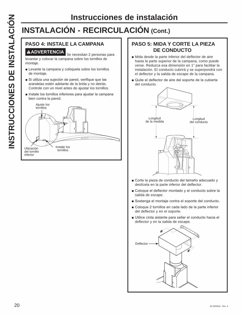
20 49-2000916 Rev. 0
PASO 4: INSTALE LA CAMPANAADVERTENCIA Se necesitan 2 personas para
levantar y colocar la campana sobre los tornillos de montaje.
Levante la campana y colóquela sobre los tornillos de montaje.
arandelas estén adelante de la brida y no detrás. Controle con un nivel antes de ajustar los tornillos.
bien contra la pared.
PASO 5: MIDA Y CORTE LA PIEZA DE CONDUCTO
Mida desde la parte inferior del deflector de aire hasta la parte superior de la campana, como puede verse. Reduzca esa dimensión en 1” para facilitar la instalación. El conducto cubrirá y se superpondrá con el deflector y la salida de escape de la campana.
del conducto.
deslícela en la parte inferior del deflector.
salida de escape.
del deflector y en el soporte.
deflector y en la salida de escape.
Ajuste los tornillos
Instale los tornillosUbicación
del tornillo inferior
Longitud de la medida
Longitud del conducto
Deflector
Instrucciones de instalaciónINSTALACIÓN - RECIRCULACIÓN (Cont.)
INST
RU
CC
ION
ES D
E IN
STA
LAC
IÓN

49-2000916 Rev. 0 21
PASO 6: CONECTE LOS ELEMENTOS ELÉCTRICOS
Verifique que la energía esté cortada en la fuente.
ADVERTENCIA Si el cableado doméstico no cuenta con un cable de 2 hilos con conexión a tierra, un instalador debe realizar una conexión a tierra. Cuando el cableado doméstico es de aluminio, asegúrese de usar un compuesto antioxidante y conectores de aluminio a cobre aprobados por UL.
y el calado sobre la parte superior izquierda.
con un alivio de tensión.
derivado.
derivado.
circuito derivado o al cable de conexión a tierra.
sobre cada conector eléctrico.
vuelva a colocar la tapa. Verifique que los cables no sufran pellizcos.
6 tornillos originales.
PASO 7: INSTALE LAS CUBIERTAS DEL CONDUCTO
Quite la tapa protectora de plástico. Arme las cubiertas del conducto de acuerdo con la aplicación.
NOTA: La cubierta del conducto superior cuenta con orificios de ventilación en un extremo previstos para ser usados cuando se instala la campana para efectuar una recirculación. Asegúrese de que el extremo con ventilación se encuentre
ventilación serán visibles en esta instalación. Deslice la cubierta del conducto superior dentro de los extremos doblados de la cubierta del conducto inferior.
Coloque las cubiertas decorativas del conducto sobre la parte superior de la campana.
Extienda la cubierta del conducto interior en dirección ascendente hacia el soporte de cielorraso.
Sujete con 2 tornillos al soporte de la cubierta del conducto. Quite el material de empaque de la abertura del filtro.
Ubique los orificios para tornillos en el extremo frontal interno de la abertura. Instale 2 tornillos para sujetar la cubierta del conducto inferior a la campana.
Tapa de la caja de conexiones
Calado
Tornillos de montaje
Orificios de ventilación
Asiento de la cubierta del conducto inferior
Soporte de la
cubierta del conducto
Cubierta del conducto inferior
Cubierta del conducto superior
Lengüetas de conexión de cubierta del
conducto
Orificios para tornillos
Instrucciones de instalaciónINSTALACIÓN - RECIRCULACIÓN (Cont.)
INSTR
UC
CIO
NES D
E INSTA
LAC
IÓN
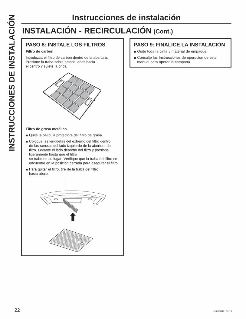
22 49-2000916 Rev. 0
PASO 8: INSTALE LOS FILTROSFiltro de carbónIntroduzca el filtro de carbón dentro de la abertura. Presione la traba sobre ambos lados hacia el centro y sujete la brida.
Filtro de grasa metálico
de las ranuras del lado izquierdo de la abertura del filtro. Levante el lado derecho del filtro y presione ligeramente hasta que el filtro se trabe en su lugar. Verifique que la traba del filtro se encuentre en la posición cerrada para asegurar el filtro.
hacia abajo.
PASO 9: FINALICE LA INSTALACIÓN Quite toda la cinta y material de empaque.
manual para operar la campana.
Instrucciones de instalaciónINSTALACIÓN - RECIRCULACIÓN (Cont.)
INST
RU
CC
ION
ES D
E IN
STA
LAC
IÓN
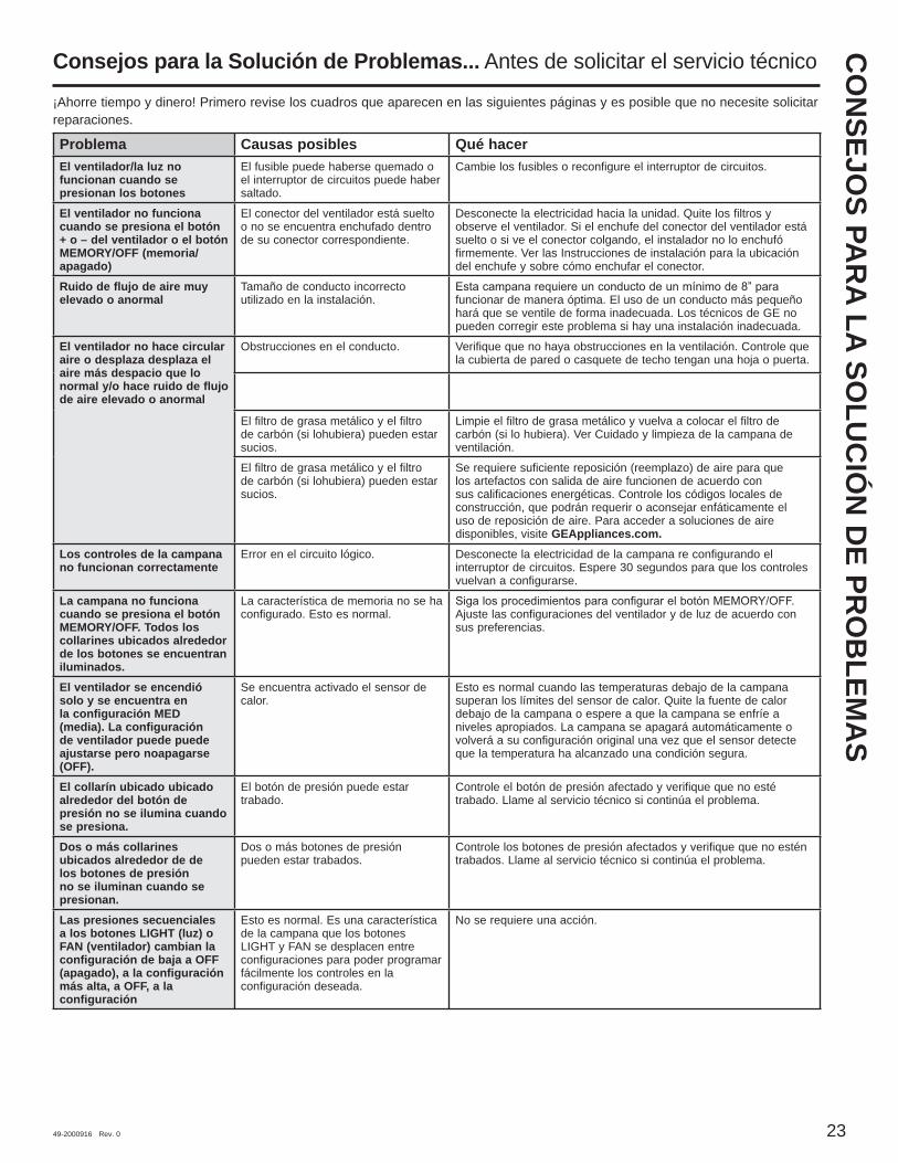
49-2000916 Rev. 0 23
Problema Causas posibles Qué hacerEl ventilador/la luz no funcionan cuando se presionan los botones
El fusible puede haberse quemado o el interruptor de circuitos puede haber saltado.
Cambie los fusibles o reconfigure el interruptor de circuitos.
El ventilador no funciona cuando se presiona el botón + o – del ventilador o el botón MEMORY/OFF (memoria/apagado)
El conector del ventilador está suelto o no se encuentra enchufado dentro de su conector correspondiente.
Desconecte la electricidad hacia la unidad. Quite los filtros y observe el ventilador. Si el enchufe del conector del ventilador está suelto o si ve el conector colgando, el instalador no lo enchufó firmemente. Ver las Instrucciones de instalación para la ubicación del enchufe y sobre cómo enchufar el conector.
Ruido de flujo de aire muy elevado o anormal
Tamaño de conducto incorrecto utilizado en la instalación. funcionar de manera óptima. El uso de un conducto más pequeño
hará que se ventile de forma inadecuada. Los técnicos de GE no pueden corregir este problema si hay una instalación inadecuada.
El ventilador no hace circular aire o desplaza desplaza el aire más despacio que lo normal y/o hace ruido de flujo de aire elevado o anormal
Obstrucciones en el conducto. Verifique que no haya obstrucciones en la ventilación. Controle que la cubierta de pared o casquete de techo tengan una hoja o puerta.
El filtro de grasa metálico y el filtro de carbón (si lohubiera) pueden estar sucios.
Limpie el filtro de grasa metálico y vuelva a colocar el filtro de carbón (si lo hubiera). Ver Cuidado y limpieza de la campana de ventilación.
El filtro de grasa metálico y el filtro de carbón (si lohubiera) pueden estar sucios.
Se requiere suficiente reposición (reemplazo) de aire para que los artefactos con salida de aire funcionen de acuerdo con sus calificaciones energéticas. Controle los códigos locales de construcción, que podrán requerir o aconsejar enfáticamente el uso de reposición de aire. Para acceder a soluciones de aire disponibles, visite GEAppliances.com.
Los controles de la campana no funcionan correctamente
Error en el circuito lógico. Desconecte la electricidad de la campana re configurando el interruptor de circuitos. Espere 30 segundos para que los controles vuelvan a configurarse.
La campana no funciona cuando se presiona el botón MEMORY/OFF. Todos los collarines ubicados alrededor de los botones se encuentran iluminados.
La característica de memoria no se ha configurado. Esto es normal. Ajuste las configuraciones del ventilador y de luz de acuerdo con
sus preferencias.
El ventilador se encendió solo y se encuentra en la configuración MED (media). La configuración de ventilador puede puede ajustarse pero noapagarse (OFF).
Se encuentra activado el sensor de calor.
Esto es normal cuando las temperaturas debajo de la campana superan los límites del sensor de calor. Quite la fuente de calor debajo de la campana o espere a que la campana se enfríe a niveles apropiados. La campana se apagará automáticamente o volverá a su configuración original una vez que el sensor detecte que la temperatura ha alcanzado una condición segura.
El collarín ubicado ubicado alrededor del botón de presión no se ilumina cuando se presiona.
El botón de presión puede estar trabado.
Controle el botón de presión afectado y verifique que no esté trabado. Llame al servicio técnico si continúa el problema.
Dos o más collarines ubicados alrededor de de los botones de presión no se iluminan cuando se presionan.
Dos o más botones de presión pueden estar trabados.
Controle los botones de presión afectados y verifique que no estén trabados. Llame al servicio técnico si continúa el problema.
Las presiones secuenciales a los botones LIGHT (luz) o FAN (ventilador) cambian la configuración de baja a OFF (apagado), a la configuración más alta, a OFF, a la configuración
Esto es normal. Es una característica de la campana que los botones LIGHT y FAN se desplacen entre configuraciones para poder programar fácilmente los controles en la configuración deseada.
No se requiere una acción.
¡Ahorre tiempo y dinero! Primero revise los cuadros que aparecen en las siguientes páginas y es posible que no necesite solicitar reparaciones.
Consejos para la Solución de Problemas... Antes de solicitar el servicio técnicoC
ON
SEJOS PA
RA LA SO
LUC
IÓN
DE PR
OB
LEMA
S

24 49-2000916 Rev. 0
Notas

49-2000916 Rev. 0 25
GA
RA
NTÍA LIM
ITAD
A
GEAppliances.comTodo el servicio de garantía es provisto por nuestros Centros de Servicio de Fabricación, o un técnico autorizado de Customer Care®. Para programar una visita del servicio técnico a través de Internet, visítenos en geappliances.com/service
Para realizar el servicio técnico de su electrodoméstico, se podrá requerir el uso de datos del puerto de abordaje para su diagnóstico. Esto da al técnico del servicio de fábrica de GE Appliances la habilidad de diagnosticar de forma rápida cualquier problema con su electrodoméstico, y de ayudar a GE Appliances a mejorar sus productos al brindarle a GE Appliances la información sobre su electrodoméstico. Si no desea que los datos de su electrodoméstico sean enviados a GE Appliances, solicitamos que le indique a su técnico no entregar los datos a GE Appliances en el momento del servicio.
Qué no cubrirá GE Appliances: Viajes del técnico del servicio a su hogar para enseñarle
sobre cómo usar el producto.
o uso para propósitos diferentes al original o uso comercial.
incendio, inundaciones o catástrofes naturales.
defectos sobre este producto.
superficie, deslustres o manchas pequeñas no informadas
la superficie) que pueden ser eliminadas siguiendo las instrucciones de limpieza.
lámparas, excepto las lámparas LED.
Garantía Limitada
EXCLUSIÓN DE GARANTÍAS IMPLÍCITASSu única y exclusiva alternativa es la reparación del producto, como se indica en la Garantía Limitada. Las garantías implícitas, incluyendo garantías implícitas de comerciabilidad o conveniencia sobre un propósito particular, se limitan a un año o al período más corto permitido por la ley.
Esta garantía limitada se extiende al comprador original y a cualquier dueño subsiguiente de productos comprados para uso hogareño dentro de EE.UU. Si el producto está en un área donde no se encuentra disponible un Proveedor Autorizado del Servicio Técnico de GE Appliances, usted será responsable por el costo de un viaje o se podrá requerir que traiga el producto a una ubicación del Servicio Técnico de GE Appliances autorizado para recibir el servicio. En Alaska, la garantía limitada excluye el costo de envío o llamadas del servicio a su hogar. Algunos estados no permiten la exclusión o limitación de daños fortuitos o consecuentes. Esta garantía limitada le da derechos legales específicos y es posible que tenga otros derechos legales que varían entre un estado y otro. Para conocer cuáles son sus derechos legales, consulte a la oficina de asuntos del consumidor local o estatal o al Fiscal de su estado.
Garante: GE Appliances, a Haier company Louisville, KY 40225
Garantías Extendidas: Adquiera una garantía extendida de GE Appliances y conozca los descuentos especiales que están disponibles mientras su garantía aún está vigente. Puede acceder a la misma a través de Internet en cualquier momento en
geappliances.com/extended-warranty
disponibles cuando su garantía caduque.
Por el Período de GE Appliances reemplazaráUn Año Desde la fecha de la compra original
Cualquier pieza del producto de cocción que falle debido a un defecto en los materiales o la fabricación. Durante esta garantía limitada de un año, GE Appliances también proveerá, sin costo, todo el trabajo y costos del servicio relacionados con el reemplazo de la pieza defectuosa.
Abroche su recibo aquí. Para acceder al servicio técnico de acuerdo con la garantía deberá contar con la prueba de la fecha original de com
pra.
26 49-2000916 Rev. 0
Printed in China
SOPO
RTE
PA
RA
EL C
ON
SUM
IDO
R Soporte para el ConsumidorSitio Web de GE Appliances¿Desea realizar una consulta o necesita ayuda con su electrodoméstico? ¡Intente a través del Sitio Web de GE Appliances las 24 horas del día, cualquier día del año! Usted también puede comprar más electrodomésticos maravillosos de GE Appliances y aprovechar todos nuestros servicios de soporte a través de Internet, diseñados para su conveniencia. En EE.UU.: GEAppliances.com
Registre su Electrodoméstico¡Registre su electrodoméstico nuevo a través de Internet, según su conveniencia! Un registro puntual de su producto permitirá una mejor comunicación y un servicio más puntual de acuerdo con los términos de su garantía, en caso de surgir la necesidad. También puede enviar una carta en la tarjeta de inscripción preimpresa que se incluye con el material embalado. En EE.UU.: GEAppliances.com/register
Servicio ProgramadoEl servicio de reparación de expertos de GE Appliances está a sólo un paso de su puerta. Conéctese a través de Internet y programe su servicio a su conveniencia cualquier día del año. En EE.UU.: GEAppliances.com/service
Garantías ExtendidasAdquiera una garantía extendida de GE Appliances y conozca los descuentos especiales que están disponibles mientras su garantía aún está vigente. La puede adquirir en cualquier momento a través de Internet. Los servicios de GE Appliances aún estarán allí cuando su garantía caduque. En EE.UU.: GEAppliances.com/extended-warranty
Piezas y AccesoriosAquellos individuos calificados para realizar el servicio técnico de sus propios electrodomésticos podrán solicitar el envío de piezas o accesorios directamente a sus hogares (se aceptan las tarjetas VISA, MasterCard y Discover). Ordene hoy a través de Internet durante las 24 horas, todos los días. En EE.UU.: GEApplianceparts.comel horario de atención comercial.Las instrucciones que figuran en este manual cubren los procedimientos que serán realizados por cualquier usuario. Otros servicios técnicos generalmente deben ser derivados a personal calificado del servicio. Se deberá tener cuidado, ya que una reparación indebida podrá hacer que el funcionamiento no sea seguro.
ContáctenosSi no se encuentra satisfecho con el servicio que recibió de GE Appliances, comuníquese con nosotros a través de nuestro sitio Web con todos los detalles, incluyendo su número telefónico, o escriba a: En EE.UU.: General Manager, Customer Relations | GE Appliances, Appliance Park | Louisville, KY 40225 GEAppliances.com/service