child-sized 3d printed igus humanoid open platform · child-sized 3d printed igus humanoid open...
TRANSCRIPT

Child-sized 3D Printed igus Humanoid Open Platform
Philipp Allgeuer, Hafez Farazi, Michael Schreiber and Sven Behnke
Abstract— The use of standard platforms in the field ofhumanoid robotics can accelerate research, and lower theentry barrier for new research groups. While many affordablehumanoid standard platforms exist in the lower size ranges ofup to 60 cm, beyond this the few available standard platformsquickly become significantly more expensive, and difficult tooperate and maintain. In this paper, the igusr Humanoid OpenPlatform is presented—a new, affordable, versatile and easilycustomisable standard platform for humanoid robots in thechild-sized range. At 90 cm, the robot is large enough to interactwith a human-scale environment in a meaningful way, and isequipped with enough torque and computing power to fosterresearch in many possible directions. The structure of the robotis entirely 3D printed, allowing for a lightweight and appealingdesign. The electrical and mechanical designs of the robot arepresented, and the main features of the corresponding open-source ROS software are discussed. The 3D CAD files for all ofthe robot parts have been released open-source in conjunctionwith this paper.
I. INTRODUCTION
The field of humanoid robotics is enjoying increasingpopularity, with many research groups from around theworld having developed platforms of all sizes and levels ofcomplexity to investigate challenges such as bipedal walking,environmental perception, object manipulation, and human-machine interaction. The nature of robots with humanlikekinematics gives them the mobility and versatility to act ineveryday environments, including eventually in the home,in a similar way to their human counterparts. The effort tostart humanoid robotics research on a real platform can behigh however, and often large amounts of time need to bespent on design, construction, firmware and software beforethe platform is sufficiently functional that the real researchtopics can be addressed. This is a barrier of time, money,and multifaceted technical expertise that can inhibit manyresearch groups from gaining entry into the humanoid field.The availability of standard robot platforms can significantlyreduce these initial hurdles, facilitating wider disseminationof humanoid robots, and greater collaboration and codeexchange between groups that share a common platform.Capable standard platforms have the ability to invigorate andaccelerate academic research, as researchers can then focuschiefly on the challenges that are most interesting to them,and contribute their advances to the state of the art in theirfield of specialisation.
A number of standard humanoid robot platforms have beendeveloped over the years, including notably the Aldebaran
All authors are with the Autonomous Intelligent Systems (AIS) Group,Computer Science Institute VI, University of Bonn, Germany. Email:[email protected]. This work was partially fundedby grant BE 2556/10 of the German Research Foundation (DFG).
23
5
20
0
20
0
40
2
25
16
0
Not to scale Lengths in mm
Fig. 1. The igusr Humanoid Open Platform and its kinematics.
Nao and the Robotis DARwIn-OP, both of which haveseen much success. The igusr Humanoid Open Platform,introduced in this paper, is shown in Fig. 1. The platformis a collaboration between researchers at the University ofBonn and igusr GmbH, a leading manufacturer of polymerbearings and energy chains. The robot has already beendemonstrated at numerous industrial trade fairs, in additionto demonstrations at the most recent RoboCup and RoboCupGerman Open. The igusr Humanoid Open Platform seeksto close the gap between small, albeit affordable, standardhumanoid platforms, and larger significantly more expensiveones such as the Honda Asimo and Boston Dynamics Atlasrobots. By developing this platform, we seek to enable teamsto work with an affordable robot of a size large enough tointeract meaningfully with the environment. Furthermore, wedesigned the platform to be as open, modular, maintainableand customisable as possible, to allow the robot to be adaptedto a variety of research tasks with minimal effort. The choiceof using almost exclusively 3D printed plastic parts for themechanical components of the robot forms the core of thisphilosophy, and also greatly simplifies the manufacture of therobots. As a result, individual parts can easily be modified,reprinted and replaced to augment the capabilities of therobot. For example, if a gripper was to be required for anapplication, it would be easy to design a replacement lowerarm part to accommodate this. As a further example of theextensibility of the platform, the internal PC also providesthe appropriate interfaces to incorporate a microphone andspeakers, if this is required. In consonance with our aims

Fig. 2. The igusr Humanoid Open Platform in size comparison with theRobotis DARwIn-OP and Darwin-Mini robots.
of producing a platform that is entirely open, the ROSmiddleware [1] was chosen as the basis of the softwaredeveloped for the igusr Humanoid Open Platform. Thispromotes the modularity, visibility, reusability, and to somedegree also the platform independence, of the produced robotsoftware in this research community-driven ecosystem. Thecomplete hardware and software designs, the former in theform of print-ready 3D CAD files [2] and the latter withdocumentation [3], are available open source.
II. RELATED WORK
Over the last decade, a number of humanoid robotic plat-forms have been introduced that demonstrate how the use ofa standard platform can accelerate research and development,by alleviating the need for teams to each ‘reinvent the wheel’for low level tasks such as communications and walking.The most prominent example of this is the Nao robot [4],developed by Aldebaran Robotics and first released publiclyin 2008. By now, many thousands of Nao robots are in useall over the world. The large dissemination was driven inpart by their use as the standard humanoid platform for theRoboCup Soccer SPL competition. The Nao comes with arich set of features, such as a variety of available gaits,a programming SDK, and well-developed human-machineinteraction components. However, at 58 cm tall, Naos oftenrequire special miniaturised environments, with objects on ascale that the robot can manipulate or step onto. Also, as aproprietary product, there are only very limited possibilitiesfor own hardware repair and customisation.
Another example of a successful standard platform is theDARwIn-OP [5], and its recent successor the ROBOTISOP2, distributed by Robotis. Both robots are quite similarin design and architecture, and stand at 45.5 cm tall, almostexactly half the size of the igusr Humanoid Open Platform.
Fig. 2 shows a size comparison between the two robots anda Darwin-Mini, which is only 27 cm tall. In contrast to theclosed proprietary design of the Nao robot, the DARwIn-OPwas designed as an open platform that allows users tooperate, maintain and customise the robot as they desire.Nevertheless, the size of the robot has remained a limitingfactor to its range of applications.
Two more recently developed platforms include the IntelJimmy robot, and the Poppy robot from the Inria Flow-ers Laboratory [6]. Both of these robots are open sourceplatforms that are for the most part 3D printed. At 65 cmtall, the Jimmy robot is intended for social interactions, andcomes with software based on the DARwIn-OP frameworkthat includes for example a walking engine. The robot onlyuses 3D printed parts for its outer shell, but its weight issupported by an internal aluminium frame. The Poppy roboton the other hand, is more completely 3D printed, and isintended as a research platform with a compliant bio-inspiredmorphology. The robot is 84 cm tall, has a multi-articulatedtrunk, and features a skeletonised design. Poppy has so faronly demonstrated walking in an assisted manner, and isgenerally intended for non-autonomous use, with persistentcabled connections to the robot and off-board processing.
Larger standard platforms, such as the Asimo [7], HRP[8] and Atlas robots, quickly run into the limitation thatthey become an order of magnitude more expensive, andmore difficult, or even dangerous, to operate and maintain.Such large robots also have a significantly lower robustnessto falling in terms of hardware damage, and require a gantryin normal use. These factors limit the possibility of the useof such robots by most research groups.
The igusr Humanoid Open Platform bridges the gapbetween the existing larger and smaller standard platforms inthat it is large enough to act in a human-scale environment,yet small enough to fall down and get back up, and lighterfor its size than all of the other robots when comparedby body mass index (BMI). The cost of the platform isabout twice that of the DARwIn-OP. In 2012, work com-menced on the first prototype of a child-sized humanoidplatform, dubbed the NimbRo-OP [9]. The NimbRo-OP wasconstructed mainly out of aluminium profiles and carboncomposite sheets, with only the head and a few other smallparts being 3D printed. The manufacturing was completedin-house, and required the milling of parts from up tofour sides, but yielded a very rigid and light-weight result.An earlier form of the ROS software was developed forthe NimbRo-OP, and both the hardware and software werereleased open source [10]. This produced quite some interestin the platform, and although it should be stated that it was anacademic as opposed to a commercial effort, several groupsfrom around the world purchased the platform, or producedvariants of their own using our hardware specifications. Theigusr Humanoid Open Platform represents the next step inthe evolution of the NimbRo-OP into a robust multifacetedhumanoid robotics platform, and is to be seen as an opencontribution to the humanoid robotics community to helpmore research groups enter the field.

TABLE I
IGUSr HUMANOID OPEN PLATFORM SPECIFICATIONS
Type Specification Value
General
Height 90 cmWeight 6.6 kgBattery 4-cell LiPo (14.8V, 3.8Ah)
Battery Life 15–30minMaterial Polyamide 12 (PA12)
PC
Product Gigabyte Brix GB-BXi7-5500CPU Intel i7-5500U (4 threads)
Frequency 2.4–3.0GHzRAM 4GB DDR3Disk 120GB SSD
Network Ethernet, Wi-Fi, BluetoothOther 4×USB 3.0, HDMI, MiniDP
CM730
Microcontroller STM32F103RE (Cortex M3)Memory 512KB Flash, 64KB SRAM
Frequency 72MHzOther 3×Buttons, 7× Status LEDs
Actuators
Total 8×MX-64, 12×MX-106Head 2×MX-64
Each Arm 3×MX-64Each Leg 6×MX-106
Sensors
Encoders 4096 ticks/revGyroscope 3-axis (L3G4200D chip)
Accelerometer 3-axis (LIS331DLH chip)Magnetometer 3-axis (HMC5883L chip)
Camera Logitech C905 (720p)Camera Lens Wide-angle lens with 150◦ FOV
III. ROBOT DESIGN CONCEPT
A summary of the main hardware specifications of theigusr Humanoid Open Platform is shown in Table I. Otherthan an appealing overall aesthetic appearance, for which adesign bureau was engaged, the main criteria for the designwere the simplicity of manufacture, assembly, maintenanceand customisation. To satisfy these criteria, a modular designapproach was used. This is evident, for example, in thechoice of using a high performance small form factor PCwith standard mounting points in a location in the torsowhere space requirements are flexible. As such, it is verysimple to upgrade the PC in the robot. If the layout of theexternal PC sockets changes, the only potentially requiredhardware change is the replacement of the white plastic coveron the back of the robot that covers the PC. As this cover isprinted in a modular fashion separately from the remainderof the torso, it is very easily replaced with a part that hasholes in the correct locations for the new PC. Since the initialNimbRo-OP prototype was built, the PC has been changedtwice to augment the computational power.
The modular design of the robot is also demonstratedby its ability to allow quick design iterations. Due to the3D printed nature of the robot, parts can be modified andreplaced with great freedom. For instance, in one of the firstiterations of the design, it was found that one of the leg partsdid not allow for an adequate range of motion in the hips.
This issue was quickly resolved with the simple change of theassociated dimensions in the CAD model, and the subsequentreprinting of the part.
IV. MECHANICAL DESIGN
While the kinematic structure of the igusr Humanoid OpenPlatform is very similar to that of the NimbRo-OP, its struc-tural design was changed fundamentally. This was motivatedlargely by the desire for a greater overall visual and aestheticappeal of the robot, but it also had many other benefits,such as a significant reduction in the total number of parts.The resulting robot design, shown in Fig. 1, was awardedthe first RoboCup Design Award in 2015, based on criteriasuch as performance, simplicity and ease of use. Whereas theNimbRo-OP consisted entirely of a strongly connected arrayof load-bearing aluminium and carbon composite structureswith no outer facade or walls, the new design consists en-tirely of the uniform white plastic exoskeleton that is visibleexternally. This facilitated a transition to cable routing inter-nally through the limbs, as opposed to the partially externalcable routing that was utilised in the NimbRo-OP. The plasticparts of the new design are 3D printed from Polyamide 12in increments of less than 0.1mm using a Selective LaserSintering (SLS) process. It is important to note that thereare no extra parts behind the outer surface that help supportthe robot structure. The exoskeleton is simultaneously load-bearing and for outward appearance, and strongly fulfilsboth these functions. This allows for dramatic space andweight savings, as evidenced by the igusr Humanoid OpenPlatform’s very low weight. The structural integrity andresistance to deformation and buckling is ensured throughmodulation of the wall thickness in the areas that requireit, and through strategic widespread use of ribs and othergeometric strengthening features, which are printed directlyas part of the exoskeleton. Essentially, through the freedomsof 3D printing, the plastic part strengths can be assignedexactly where they are needed, and not unnecessarily in otherlocations. This is a second reason why the weight of the newmechanical design is so low. If a weak spot is identifiedthrough practical experience, as indeed happened duringwalking tests, the parts can locally be strengthened in theCAD design without significantly impacting the remainderof the design.
The kinematic structure of the robot is shown in Fig. 1.Starting from the trunk, the head can first yaw and thenpitch, and the arms first pitch and then roll in the shoulder,before allowing pitch again in the elbow joint. There arethree degrees of freedom (DOF) in each hip—first yaw, thenroll and then pitch—one DOF in each knee, and two DOFin each ankle—first roll and then pitch. Position controlledRobotis Dynamixel MX-64 and MX-106 servos are usedfor all of the actuators, and mechanically form the soleconnections between the parts, except for in the hips, whereigusr axial thrust bearings provide the required dry rubbingself-lubrication.
Two noteworthy changes in the kinematics over the Nim-bRo-OP, are that the feet are more strongly reinforced—

DC Power
Battery
Power Board
CM730 Ubuntu PC
Camera
MX106 Leg Actuators
MX64 Head / Arm Actuators
LED / Button Panel
3-axis Magnetometer
Mouse Keyboard
External Monitor
1 DC Power
2 Digital I/O
3 DXL Bus
4 USB
5 Other
Ethernet Wi-Fi
Bluetooth
1
1
1
1
5
4
5 1 1 3
4 2 2 4
Fig. 3. System block diagram of the electronic components and connectionsin the igusr Humanoid Open Platform.
increasing their rigidity to elastic deformation—and that themount point for the ankle is further back on the foot. Thisreduces the effect that the backlash in the ankle pitch actuatorhas on the stability and balance of the robot during walking,and avoids similar effects caused by bending of the feet underunbalanced loads.
V. ELECTRONICS
Other than for an upgrade of the PC, the electrical designof the igusr Humanoid Open Platform has remained verysimilar to that of the NimbRo-OP prototype, which in turnwas inspired by the configuration of the DARwIn-OP robot.A block diagram of the electrical subsystem of the robotdesign is shown in Fig. 3. At the heart of the electrical designis the Robotis CM730 sub controller board, which containspower management features, management of a Dynamixelbus, and a Cortex M3 STM32F103RE microcontroller run-ning at 72MHz, alongside numerous other peripheral fea-tures. The CM730 is connected via USB to a PC running afull 64-bit Ubuntu operating system. All of the robot controlsoftware and processing runs on this Intel i7-5500U PC.DC power is provided to the system via a power board thatincorporates a switch for the entire robot. One or both DCpower and a 4-cell Lithium Polymer (LiPo) battery can beconnected, and the higher voltage of the two is forwarded tosupply all electronics of the robot.
The main purpose of the CM730 is to electrically interfacethe eight MX-64 and twelve MX-106 servos, all connectedon a single Dynamixel bus. In the igusr Humanoid OpenPlatform design, the use of servo daisy-chaining has beenkept to a minimum for stability and robustness reasons. Fiveseparate connectors on the side of the CM730 are usedto create a star topology, with daisy-chaining only beingrequired for mechanical reasons in the elbow and anklejoints. The actuators are used in position control mode, andprovide joint encoder feedback with a resolution of 4096ticks per revolution via the Dynamixel bus.
Due to a number of factors, including reliability, per-formance, data latency, throughput and changed electricalconnections, the standard shipped firmware of the CM730did not satisfy the requirements of the igusr HumanoidOpen Platform. As a result, the firmware of the CM730 wasfundamentally redesigned and completely rewritten. Many
Utilities
Motion Control Behaviours Vision
Behaviour Control
CM730
Hardware Interface
Robot Control
Trajectory Editor
Motion Modules
Localisation
Vision Processing
Vision Tools
Camera Driver
Motion Files
URDF Model
Gazebo Simulator
Network Interface
Camera
Visualisation Tools
Parameter Tuner
Logger Configuration
Server
Fig. 4. Architecture of the igusr Humanoid Open Platform ROS software.
changes and improvements were made in the process, themost notable of these being an extension of the Dynamixelprotocol for communications between the CM730 and thePC. These extensions translated into significant gains in busstability and error tolerance, as well as in time savings forbulk reads of servo data. It should be noted however, that theupgraded communications protocol is fully back-compatiblewith the standard Dynamixel protocol.
In addition to the actuators, the CM730 also connects toan interface panel that contains three buttons, five LEDs andtwo RGB LEDs. These elements are managed by the PC,and can be used to display information about the internalstate of the robot, and provide control triggers. The CM730incorporates a 3-axis gyroscope and a 3-axis accelerometer.An additional 3-axis magnetometer is connected via an I2Cinterface to the onboard microcontroller. The resulting 9-axisIMU is polled at high frequency and placed into registersthat can be queried by the PC. A 720p Logitech C905USB camera, located in the head of the robot and fittedwith a 150◦ FOV wide-angle lens, is connected directly tothe PC. Further available external connections to the PCinclude USB, HDMI, Mini DisplayPort, Gigabit Ethernet,IEEE 802.11b/g/n Wi-Fi, and Bluetooth 4.0. By default, theEthernet network interface of the PC is configured system-wide to automatically switch between static and DHCPconnections as required, also allowing simultaneous use ofthe static secondary IP address while DHCP is active.
VI. SOFTWARE ARCHITECTURE
The software that has been developed for the igusr Hu-manoid Open Platform is a continuous evolution of the C++ROS-based software that was written for the NimbRo-OP[10], and is available open source [3]. The overall softwarearchitecture, illustrated in Fig. 4, has not fundamentallychanged since the release of the NimbRo-OP software. Many
new software components have been added though, and theindividual components that already existed have undergonevast changes and improvements to enhance functionality,reliability and robustness. The software was developed underthe guise and target application of humanoid robot soccer[11], but with suitable adaptation of the behaviour control,vision processing and motion module sections, softwarefor virtually any other application can be realised. This ispossible because of the strongly modular way in whichthe software was written, greatly supported by the naturalmodularity of ROS. In many parts of the software framework,like for example in the choice of gait, plugin schemes areused for exactly this purpose, and individual tasks have beenseparated as much as possible into different nodes, often withgreat independence.
At the heart of the lower level control section of theigusr Humanoid Open Platform is the Robot Control ROSnode, which runs a hard real-time control loop that managessensor and actuator communications, state estimation andmotion generation. A URDF (Unified Robot DescriptionFormat) model of the robot is loaded from file, and aper-launch configurable selection of motion module pluginsuse this information in addition to sensory perception togenerate dynamic motions for the robot. A further hardwareinterface plugin scheme is used to manage the physicalcommunications with the robot, or interfaces to a virtualdummy robot or a physically simulated one in the Gazebosimulator. The higher level planning and artificial intelli-gence is implemented in a Behaviour Control ROS node,based on the hierarchical Behaviour Control Framework[12]. Processing of the camera images is implemented ina separate vision processing ROS node, which publishes theinformation required by the behaviours and the localisationROS nodes. A number of framework-wide helper nodes havealso been implemented, of which the visualisation tools,configuration server and logger find the most prominent use.The configuration server is a centralised storage locationand manager for software parameters, and replaces the ROSparameter server for dynamic reconfiguration of the software,and the parameter tuner GUI allows live modification of theparameters. Typically, the visualisation tools and parametertuner are run on an external PC, but the configuration serverand logger are run on the robot.
VII. DYNAMIC MOTION GENERATION
A. Compliant Actuation
In controlling the actuators of a robot, it is desirable tohave a controller that can follow commanded trajectories,but at the same time remain compliant [13]. In the caseof the igusr Humanoid Open Platform, inverse dynamicscalculations from the RBDL library [14] are used in a feed-forward manner to predict the torques that are required inorder to follow a particular joint command. These torquesare then used to improve tracking performance, and allowmore compliant settings to be used in the Dynamixel actuatorcontrol loops. Based on the robot state, support coefficientsare estimated for each limb, and the inverse dynamics are
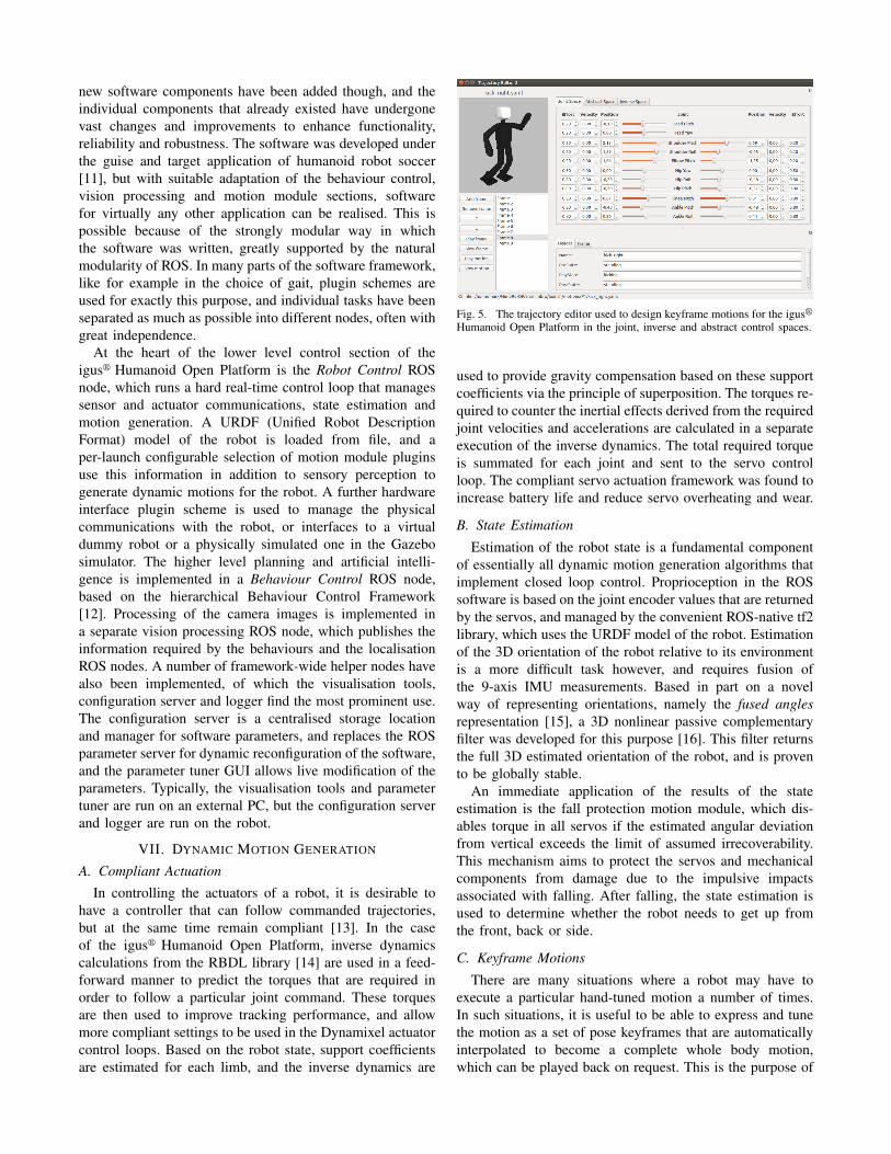
Fig. 5. The trajectory editor used to design keyframe motions for the igusrHumanoid Open Platform in the joint, inverse and abstract control spaces.
used to provide gravity compensation based on these supportcoefficients via the principle of superposition. The torques re-quired to counter the inertial effects derived from the requiredjoint velocities and accelerations are calculated in a separateexecution of the inverse dynamics. The total required torqueis summated for each joint and sent to the servo controlloop. The compliant servo actuation framework was found toincrease battery life and reduce servo overheating and wear.
B. State Estimation
Estimation of the robot state is a fundamental componentof essentially all dynamic motion generation algorithms thatimplement closed loop control. Proprioception in the ROSsoftware is based on the joint encoder values that are returnedby the servos, and managed by the convenient ROS-native tf2library, which uses the URDF model of the robot. Estimationof the 3D orientation of the robot relative to its environmentis a more difficult task however, and requires fusion ofthe 9-axis IMU measurements. Based in part on a novelway of representing orientations, namely the fused anglesrepresentation [15], a 3D nonlinear passive complementaryfilter was developed for this purpose [16]. This filter returnsthe full 3D estimated orientation of the robot, and is provento be globally stable.
An immediate application of the results of the stateestimation is the fall protection motion module, which dis-ables torque in all servos if the estimated angular deviationfrom vertical exceeds the limit of assumed irrecoverability.This mechanism aims to protect the servos and mechanicalcomponents from damage due to the impulsive impactsassociated with falling. After falling, the state estimation isused to determine whether the robot needs to get up fromthe front, back or side.
C. Keyframe Motions
There are many situations where a robot may have toexecute a particular hand-tuned motion a number of times.In such situations, it is useful to be able to express and tunethe motion as a set of pose keyframes that are automaticallyinterpolated to become a complete whole body motion,which can be played back on request. This is the purpose of

the motion player in the ROS software, which implementsa generic nonlinear keyframe interpolator that, given thedesired keyframe time intervals, is able to smoothly connectspecifications of joint positions and velocities. In addition tothis, the keyframe interpolator can also modulate the jointefforts and support coefficients (refer to Section VII-A) usedduring the motion. This allows the compliant servo actuationframework to be used meaningfully during motions withchanging support conditions.
To make the keyframe motion player practicable however,a suitable tool for the editing of raw motion specification filesis also required. Fig. 5 shows a screenshot of the trajectoryeditor that was developed for the igusr Humanoid OpenPlatform. With this editor, all aspects of the motion filescan be edited in a user-friendly environment, and with aninteractive 3D preview of the robot poses. What distinguishesthis editor is that the keyframes can be edited either in:
• Joint space, by direct manipulation of the joint angles,• Inverse space, by specification of the limb end effector
(i.e. foot, hand) poses in terms of Cartesian coordinatesand a 3D orientation, or
• Abstract space, by specification of the required arm,foot and leg parameters.
The last of the three spaces, the abstract space, is a space thatwas developed specifically for legged robots in the contextof walking and balance [17]. It abstracts the pose of the limbof a robot, nominally a leg, into specifications of the requiredleg extension, x and y rotations of the foot relative to thetrunk, and x, y and z rotations of the leg centre line relativeto the trunk, following the Euler ZXY convention. The legcentre line is defined to be the line joining the centre of thehip joint and the ankle joint. Basic trigonometric conversionsbetween joint space and abstract space exist.
Motions that have been designed using the trajectory editorinclude kicking, waving, demonstration and get-up motions.The waving and demonstration motions have been used atvarious industrial trade fairs for publicity and interactionpurposes. The kicking motions are relatively dynamic, andare able to propel a size 4 FIFA ball 3.5m across 32mmblade length artificial grass, which provides a high rollingresistance. A still image of the kicking motion is shown inFig. 6. The two main get-up motions of the igusr HumanoidOpen Platform are also shown in the same figure. Fouradditional get-up motions handle the cases where the robot islying on its side. With help of the support coefficients feature,the get-up motions can be efficient and controlled, and areconsiderably faster and more dynamic than those of mostother robots of comparable size. In fact, there are extendedleg flight phases during both the prone and supine get-upmotions, where the only points of contact of the robot withthe ground are the tips of the two arms, during which time thelegs of the robot are swung underneath it. The get-up motionsfrom the prone and supine positions take 3 and 4 secondsrespectively, measured from the moment that the robot startsto fade in its torque to when the robot is supported in abalanced way on only its two feet.
Fig. 6. Dynamic get-up motions of the igusr Humanoid Open Platform,from the prone (top row) and supine (bottom row) lying positions, and astill image of the dynamic kick motion.
D. Gait Generation
Motivated by the changed game environment at theRoboCup competition—the chosen application domain forour own use of the igusr Humanoid Open Platform—the gaitgeneration has been adapted to address the new challenge ofwalking on artificial grass. The use of a soft, deformable andunpredictable walking surface imposes extra requirements onthe walking algorithm. Removable rubber cleats have beenadded at the four corners underneath each foot of the robotto improve the grip on the artificial grass. This also has theeffect that the ground reaction forces are concentrated overa smaller surface area, mitigating at least part of the contactvariability induced by the grass.
The walking gait in the ROS software is based on an openloop central pattern generated core that is calculated from agait phase angle that increments at a rate proportional tothe desired gait frequency. This open loop gait is formulatedin a combination of the abstract and inverse pose spaces(see Section VII-C), and extends the open loop gait of ourprevious work [18]. The main changes that have been madeinclude:
• The integration of an explicit double support phase ofconfigurable length for greater walking stabilisation andpassive damping of oscillations,
• The modification of the leg extension profiles to transi-tion more smoothly between swing and support phases,
• The incorporation of a sagittal leg angle term that trimsthe angle relative to the ground at which the feet arelifted during stepping,
• The addition of a support coefficient transitioning pro-file for use with the compliant servo actuation,
• The use of a dynamic pose blending algorithm to enablesmoother transitions to and from walking,
• The adaptation of the gait command velocity-basedleaning strategy to use a hip motion instead of a legangle motion, and
• The introduction of a gait command acceleration-basedleaning strategy.
A number of simultaneously operating basic feedback mech-anisms have been built around the open loop gait core

Fig. 7. An image captured by the robot with ball (red circle), field line(green lines), field boundary (thin yellow lines), goal post (thick yellowlines) and crossbar (red line) detections annotated.
to stabilise the walking. The feedback in each of thesemechanisms derives from the fused pitch and fused roll [15]state estimates.
Virtual Slope Walking: If the robot is walking with anon-zero velocity in the sagittal direction and begins to tipeither forwards or backwards, there is a possibility that due tothe leg swing motion the swing foot unintentionally collideswith the ground. This causes premature contact of the footwith the ground, and the robot briefly pushes its leg in adirection that undesirably promotes further tipping of therobot. Virtual slope walking adjusts the inverse kinematicsheight of the feet in proportion to their swing state andmeasured sagittal torso angle in such a way that the roboteffectively lifts its feet more for foot placements if it istipping in the direction in which it is walking.
Fused Angle Deviation Pose Feedback: During regularstable open loop walking, the torso attitude undergoes regularlimit cycles in both the lateral and sagittal directions. Thesetrajectories are modelled in terms of fused pitch and fusedroll using parameterised sinusoids that are functions ofthe gait phase. During walking, deviations to the expectedtrunk attitude are used to construct proportional, integraland derivative feedback terms. The proportional feedbackterm is obtained by applying deadband to the output of amean filter that takes the fused angle deviations as its input,while the integral feedback term is obtained by applying anexponentially weighted integrator to the fused angle devia-tions. The derivative feedback term is obtained by applying afirst order differentiating weighted line of best fit filter. Thisinherently provides enough smoothing on the differentiatedoutput for feedback purposes. A matrix of gains is applied tothe PID feedback vector, and the resulting feedback signalsare applied to a set of stabilising mechanisms, namely phasedoffsets to the foot angle, leg angle, hip angle, arm angle andinverse kinematics centre of mass (CoM) position. This hasthe effect, for example, that the front of the support footis pushed down into the ground, and the arms are movedbackwards, when the robot is tipping forwards. The integralfeedback terms work on a slower time scale, and essentially
Fig. 8. An image captured by the robot with the undistortion model applied.
learn stabilising offsets to the central pose of the gait.Fused Angle Deviation Timing Feedback: While the
fused angle pose feedback attempts to force the robot backinto a regular gait limit cycle, the deviation timing feedbackinstead adapts the timing of the gait based on the deviation ofthe fused angle. It does this by adding proportional feedbackfrom the current fused roll deviation to the rate of progressionof the gait phase. Thus, if for example the robot starts totip outwards over a support foot, the error in the fused rollcauses the rate of the gait phase to slow down, effectivelycausing the robot to wait longer before attempting to land thenext step. The opposite situation of an unbalance towards theswing foot would cause a speed up of the gait phase, causingthe robot to land its next step sooner. A region of deadbandensures that small natural deviations in the fused roll do notinject timing noise into the gait.
Resulting Gait: With these feedback mechanisms inplace, an omnidirectional gait was achieved on an artificialgrass of 32mm blade length, with a walking speed of ap-proximately 21 cm s−1. The cleats made a clear difference tothe resulting stability of the gait, by reducing the sensitivityof the gait to the surface that the robot was walking on. Onrare occasions, when the expected timing of the gait was toogreatly disturbed by the grass during walking, the cleats gotcaught in the blades, causing further disturbances. In manycases however, even such situations were recoverable and didnot necessarily lead to a fall.
VIII. VISION SYSTEM
The igusr Humanoid Open Platform is nominally fittedwith a single 720p Logitech C905 camera behind its righteye. A second such camera can be mounted behind the lefteye however, if needed for stereo vision. The camera is fittedwith a wide-angle lens, yielding a field of view of 150◦.The choice of lens was optimised from the first NimbRo-OPprototype to increase the number of usable pixels and reducethe level of distortion, all without significantly sacrificingthe effective field of view. The Video4Linux2 camera driverused in the ROS software nominally retrieves camera imagesat 30Hz in 24bpp BGR format at a resolution of 640×

480. For further processing, including for example coloursegmentation, the captured image is converted to the HSVcolour space. In our target application of soccer, the visionprocessing tasks include field, ball, goal, line, centre circleand obstacle detection. A sample output of the detections inan image captured by the robot is shown in Fig. 7.
Due to the significant recent changes in the rules of theRoboCup Humanoid League—relating largely to the visualfeatures of the soccer field, including the introduction of amostly white ball and white goals—new detection routineswith reduced dependence on colour segmentation have beendeveloped. For ball and goal detection, a histogram oforiented gradients (HOG) descriptor is applied in the form ofa cascade classifier, with use of the AdaBoost technique. Setsof positive and negative samples are gathered directly fromthe robot camera, and used to train the classifier. Trainingwith 20 stages, 400 positive and 700 negative samples takesabout 10 hours, and the resulting classifier has a successrate above 80% on a walking robot, with very few falsedetections. As the HOG feature extraction is computationallyexpensive if applied to the whole image, some preprocessingsteps are included to reject parts of the scene that do notcontain objects of interest.
Due to the new artificial grass field in the humanoidleague, line detection based on colour segmentation is nolonger easily possible, mainly because the painted lines areno longer a clear white. Instead, an edge detector is usedon the image brightness, followed by a probabilistic HoughTransform for line segment detection. The resulting linesegments are filtered and merged based on their relativedetected position in world coordinates. Shorter line segmentsare used to try to extract the field circle, and longer ones areused to update the localisation.
Due to the use of a wide-angle lens, a distortion modelwas required to be able to project points in the cameraimage into world coordinates. The distortion model usedby OpenCV was adapted for the igusr Humanoid OpenPlatform, which uses two tangential and six radial distortioncoefficients, in addition to the four standard intrinsic cameraparameters. Due to incorrect performance of the OpenCVpoint undistortion function, a more efficient and accuratecustom undistortion algorithm based on the Newton-Raphsonmethod was designed and implemented. Fig. 8 illustrates theeffect of undistortion on images captured by the robot.
IX. CONCLUSION
The igusr Humanoid Open Platform represents a signifi-cant advancement over the previously released NimbRo-OProbot towards a robust, affordable, versatile, and customis-able open standard platform for humanoid robots in the child-sized range. The robot has proven to have many positivemechanical attributes, due largely to its modular design andadvanced 3D printing manufacturing process that allowsfor near arbitrary flexibility in the design. The completemechanical and electrical subsystems of the robot have been
described in this paper, in addition to selected features ofthe developed ROS software, which remains a continualdevelopment effort. We have released the hardware andsoftware open source to the community in the hope thatit will benefit other research groups around the world, andthat it will encourage them to also publish their results as acontribution to the open source community.
X. ACKNOWLEDGEMENTS
We would like to acknowledge the contributions of igusr
GmbH to the project, in particular the management of MartinRaak towards the robot design and manufacture.
REFERENCES
[1] M. Quigley, K. Conley, B. P. Gerkey, J. Faust, T. Foote, J. Leibs,R. Wheeler, and A. Ng, “ROS: An open-source robot operatingsystem,” in ICRA Workshop on Open Source Software, 2009.
[2] igus GmbH. (2015, Oct) igus Humanoid Open Platform HardwareCAD Data. [Online]. Available: https://github.com/igusGmbH/HumanoidOpenPlatform
[3] NimbRo. (2015, Oct) igus Humanoid Open Platform ROS Software.[Online]. Available: https://github.com/AIS-Bonn/humanoid_op_ros
[4] D. Gouaillier, V. Hugel, P. Blazevic, C. Kilner, J. Monceaux, P. Lafour-cade, B. Marnier, J. Serre, and B. Maisonnier, “Mechatronic designof NAO humanoid,” in Int. Conf. on Robotics and Automation, 2009.
[5] I. Ha, Y. Tamura, H. Asama, J. Han, and D. Hong, “Development ofopen humanoid platform DARwIn-OP,” in SICE Annual Conf., 2011.
[6] M. Lapeyre, P. Rouanet, J. Grizou, S. Nguyen, F. Depraetre, A. Le Fal-her, and P.-Y. Oudeyer, “Poppy Project: Open-Source Fabrication of3D Printed Humanoid Robot for Science, Education and Art,” inDigital Intelligence 2014, Sep 2014.
[7] K. Hirai, M. Hirose, Y. Haikawa, and T. Takenaka, “The developmentof Honda humanoid robot,” in Int. Conf. on Rob. and Autom., 1998.
[8] K. Kaneko, F. Kanehiro, M. Morisawa, K. Miura, S. Nakaoka, andS. Kajita, “Cybernetic human HRP-4C,” in Proceedings of 9th IEEE-RAS Int. Conf. on Humanoid Robotics (Humanoids), 2009, pp. 7–14.
[9] M. Schwarz, M. Schreiber, S. Schueller, M. Missura, and S. Behnke,“NimbRo-OP Humanoid TeenSize Open Platform,” in 7th Workshopon Humanoid Soccer Robots, Int. Conf. on Humanoid Robots, 2012.
[10] P. Allgeuer, M. Schwarz, J. Pastrana, S. Schueller, M. Missura, andS. Behnke, “A ROS-based software framework for the NimbRo-OPhumanoid open platform,” in 8th Workshop on Humanoid SoccerRobots, Int. Conference on Humanoid Robots, 2013.
[11] M. Schwarz, J. Pastrana, P. Allgeuer, M. Schreiber, S. Schueller,M. Missura, and S. Behnke, “Humanoid TeenSize Open PlatformNimbRo-OP,” in Proceedings of 17th RoboCup International Sym-posium, Eindhoven, Netherlands, 2013.
[12] P. Allgeuer and S. Behnke, “Hierarchical and state-based architecturesfor robot behavior planning and control,” in Proceedings of 8thWorkshop on Humanoid Soccer Robots, IEEE-RAS Int. Conferenceon Humanoid Robots, Atlanta, USA, 2013.
[13] M. Schwarz and S. Behnke, “Compliant robot behavior using servo ac-tuator models identified by iterative learning control,” in Proceedingsof 17th RoboCup Int. Symposium, Eindhoven, Netherlands, 2013.
[14] M. Felis. (2015, Jun) Rigid Body Dynamics Library. [Online].Available: http://rbdl.bitbucket.org/
[15] P. Allgeuer and S. Behnke, “Fused Angles: A representation of bodyorientation for balance,” in Int. Conf. on Intelligent Robots and Systems(IROS), Hamburg, Germany, 2015.
[16] P. Allgeuer and S. Behnke, “Robust sensor fusion for biped robotattitude estimation,” in Proceedings of 14th IEEE-RAS Int. Conferenceon Humanoid Robotics (Humanoids), Madrid, Spain, 2014.
[17] S. Behnke, “Online trajectory generation for omnidirectional bipedwalking,” in Proceedings of 2006 IEEE International Conference onRobotics and Automation, Orlando, USA, 2006.
[18] M. Missura and S. Behnke, “Self-stable omnidirectional walking withcompliant joints,” in Proceedings of 8th Workshop on HumanoidSoccer Robots, Int. Conf. on Humanoid Robots, 2013.