check point lights out management administration guide · check point lights out management...
TRANSCRIPT

10 October 2013
Administration Guide
Check Point Lights Out Management
Check Point 12000, 4800, TE100, and
TE250 Appliances

© 2013 Check Point Software Technologies Ltd.
All rights reserved. This product and related documentation are protected by copyright and distributed under licensing restricting their use, copying, distribution, and decompilation. No part of this product or related documentation may be reproduced in any form or by any means without prior written authorization of Check Point. While every precaution has been taken in the preparation of this book, Check Point assumes no responsibility for errors or omissions. This publication and features described herein are subject to change without notice.
RESTRICTED RIGHTS LEGEND:
Use, duplication, or disclosure by the government is subject to restrictions as set forth in subparagraph (c)(1)(ii) of the Rights in Technical Data and Computer Software clause at DFARS 252.227-7013 and FAR 52.227-19.
TRADEMARKS:
Refer to the Copyright page (http://www.checkpoint.com/copyright.html) for a list of our trademarks.
Refer to the Third Party copyright notices (http://www.checkpoint.com/3rd_party_copyright.html) for a list of relevant copyrights and third-party licenses.

Important Information Latest Software
We recommend that you install the most recent software release to stay up-to-date with the latest functional improvements, stability fixes, security enhancements and protection against new and evolving attacks.
Latest Documentation
The latest version of this document is at: (http://supportcontent.checkpoint.com/documentation_download?ID=12676)
To learn more, visit the Check Point Support Center (http://supportcenter.checkpoint.com).
Revision History
Date Description
10 October 2013 Added support for TE1000 and TE250 appliances
2 June 2013 LOM version 1.35 firmware released. The fields in these pages are changed in this version:
Network (on page 16)
Users (on page 21)
LDAP Configuration (on page 24)
14 October 2012 Added Querying Multiple Groups (on page 25).
24 July 2012 Improved formatting and updated link in Firmware Update (on page 15).
24 June 2012 Added list of open ports to Connecting to Lights Out Management (on page 5).
27 December 2011 Updated descriptions of WebUI.
Added Mapping a Virtual Drive (on page 10).
6 November 2011 First release of this document.
Feedback
Check Point is engaged in a continuous effort to improve its documentation.
Please help us by sending your comments (mailto:[email protected]?subject=Feedback on Check Point Lights Out Management Administration Guide).

Contents
Important Information ............................................................................................. 3 Check Point Lights Out Management Overview ................................................... 5
Introduction ......................................................................................................... 5 Connecting to Lights Out Management................................................................ 5
Using Lights Out Management WebUI .................................................................. 6 WebUI Requirements .......................................................................................... 6 Users and Privileges ............................................................................................ 6 Logging In and Out of the WebUI ........................................................................ 6
Appliance Control from the WebUI ........................................................................ 7 Power Monitoring and Controlling ........................................................................ 7 Remote Console .................................................................................................. 8
Launching the Java KVM Client ...................................................................... 8 Launching the Java VM .................................................................................. 9 Mapping a Virtual Drive ..................................................................................10
Remote Console Configuration ...........................................................................11 Event Log ...........................................................................................................12 Last Fault Screen ...............................................................................................13 Email Alert Setting ..............................................................................................13
LOM Management from the WebUI ...................................................................... 15 Firmware ............................................................................................................15 Firmware Update ................................................................................................15 Network ..............................................................................................................16
Configuring LOM Interface .............................................................................17 Failed Login Attempts .........................................................................................19 Certificate ...........................................................................................................20 Users ..................................................................................................................21
Configuring Users ..........................................................................................22 Web ....................................................................................................................23 Sessions .............................................................................................................23 LDAP Configuration ............................................................................................24
Querying Multiple Groups ..............................................................................25 Creating New User (Linux) .............................................................................25 Creating New User (Windows) .......................................................................26
RADIUS ..............................................................................................................28 Utilities ................................................................................................................29
Resetting the LOM Card through the BIOS ......................................................... 30

Check Point Lights Out Management Administration Guide | 5
Chapter 1
Check Point Lights Out Management Overview
In This Chapter Introduction 5
Connecting to Lights Out Management 5
Introduction The Check Point Lights Out Management (LOM) is an optional card that you can use with Check Point appliances. You can remotely control Check Point appliances using a dedicated management channel. Lights Out Management also works when the appliance is turned off or not responding.
Lights Out Management includes these components:
WebUI - A browser interface that lets you log in to the appliance and perform system management and monitoring.
Remote Console/Java Client - The Java client supports Remote Console functionality and lets you use the appliance CLI and manage local storage devices.
Note - When using the Lights Out Management WebUI, you may not see all the windows shown in this guide. The windows in the WebUI depend on the LOM card firmware version.
Supported Appliances
These Check Point appliances support this Lights Out Management card:
Check Point 4800
Check Point 12000 Appliances
TE Appliances
Connecting to Lights Out Management Connect Lights Out Management to the network using an Ethernet cable. It supports static IP addresses and DHCP (Dynamic Host Configuration Protocol).
To connect a client to Lights Out Management:
1. Connect the LOM Ethernet port to the LAN.
2. Configure the Local Area Connection of the client to the same subnet as Lights Out Management.
For example: the Lights Out Management default IP address is 192.168.0.100. Configure the client
to 192.168.0.101.
3. Make sure that these ports are open to use all the Lights Out Management features.
80
427
443
2068
8195

Check Point Lights Out Management Administration Guide | 6
Chapter 2
Using Lights Out Management WebUI
In This Chapter WebUI Requirements 6
Users and Privileges 6
Logging In and Out of the WebUI 6
WebUI Requirements A web browser. The Java KVM and VM clients are only supported on Internet Explorer and Chrome.
Java™ software installed on the local computer.
Users and Privileges You can configure Lights Out Management user accounts with these privileges:
Administrator - Configure settings in all windows.
Operator - Configure settings in all windows except Users and cannot launch Java KVM and VM clients.
User – View most of the windows in the WebUI.
Logging In and Out of the WebUI Lights Out Management loads automatically when the appliance is connected to a power source.
When you are using the WebUI:
Disable the proxy server settings on the browser.
Do not use the browser to refresh or close windows. Use Refresh and Logout in the WebUI.
To log in to the WebUI:
1. Enter the IP address of Lights Out Management into the browser.
Default: https://192.168.0.100
A Security certificate alert message opens.
2. Click Continue to this website.
The Lights Out Management login window appears.
3. Enter your user name and password.
Default user name: admin (with Administrator privileges)
Default password: admin
4. Click Login.
The Power Control window opens.
Important - Change the default password to prevent unauthorized access to the appliance.
Check Point Lights Out Management Administration Guide | 7
Chapter 3
Appliance Control from the WebUI
In This Chapter Power Monitoring and Controlling 7
Remote Console 8
Remote Console Configuration 11
Event Log 12
Last Fault Screen 13
Email Alert Setting 13
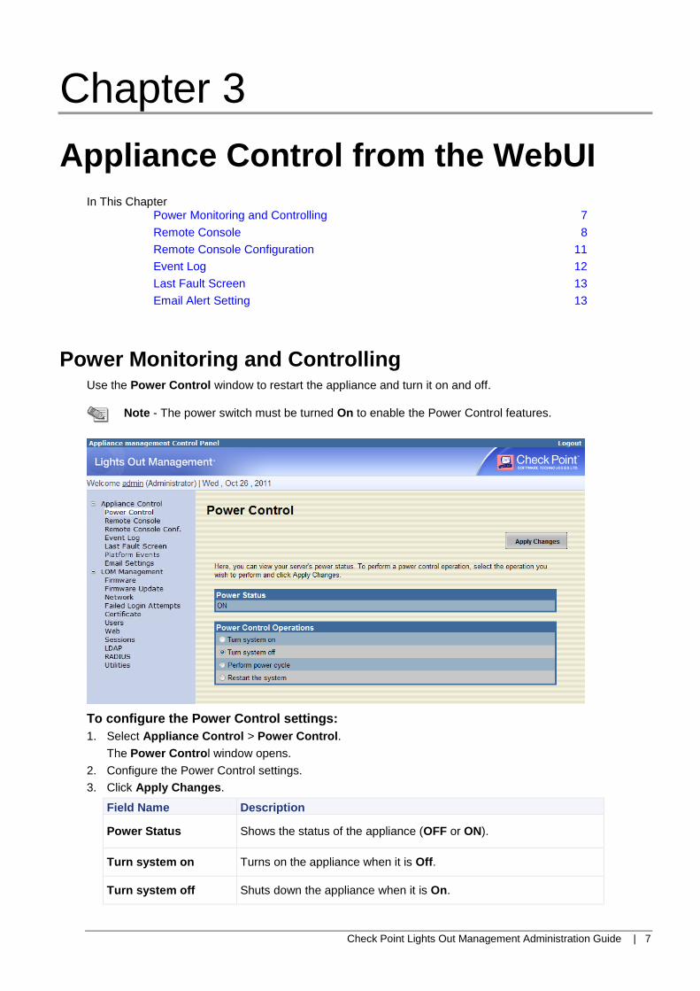
Power Monitoring and Controlling Use the Power Control window to restart the appliance and turn it on and off.
Note - The power switch must be turned On to enable the Power Control features.
To configure the Power Control settings:
1. Select Appliance Control > Power Control.
The Power Control window opens.
2. Configure the Power Control settings.
3. Click Apply Changes.
Field Name Description
Power Status Shows the status of the appliance (OFF or ON).
Turn system on Turns on the appliance when it is Off.
Turn system off Shuts down the appliance when it is On.

Appliance Control from the WebUI
Check Point Lights Out Management Administration Guide | 8
Field Name Description
Perform power cycle Shuts down the appliance and then starts it up (cold boot).
Restart the system Restarts the appliance (warm boot).
Remote Console Use the Remote Console window to launch the Java client console windows. You can also show the settings for the remote consoles.
The Java KVM client opens a virtual console for the appliance. The Java VM client accesses ISO images on your local computer and lets you upload them to the appliance.
Launching the Java KVM Client
Launch the Java KVM client to open a console window and use the appliance CLI.
To launch the Java KVM client:
1. Select Appliance Control > Remote Console.
The Remote Console window opens.
2. Click Launch Java KVM Client to start the remote console application.
The WebCheck window opens.
3. Click Open.
A Warning Security window opens.
4. Click Run.

Appliance Control from the WebUI
Check Point Lights Out Management Administration Guide | 9
The Video Viewer opens, and shows the CLI for the appliance.
5. To configure the console settings:
a) Select Tools > Session Options.
b) Click the General, Mouse, or Video Quality tab.
c) Configure the settings for your system.
d) Click OK.
6. To create a screen capture of the console window:
a) Select File > Capture to File.
b) The Save window opens.
Enter the file name and select the location for the screen capture.
c) Click Save.
The screen capture is saved as a JPG file.
7. To send a message to other administrators who are using the Java KVM client:
a) Select Tools > Instant Messaging.
The Instant Messaging window opens.
b) In Compose, enter the message.
c) Click Send.
The Message Log section shows all the messages. The messages are deleted when the client is closed.
Launching the Java VM
Launch the Java VM client to manage virtual drives or ISO images on your local computer. You can then upload files to the appliance.
Note - CDs, DVDs, and ISO files can only have Read Only privileges.

Appliance Control from the WebUI
Check Point Lights Out Management Administration Guide | 10
To launch the Java VM client:
1. Select Appliance Control > Remote Console.
The Remote Console window opens.
2. Click Launch Java VM Client.
The WebCheck window opens.
3. Click Open.
A Warning Security window opens.
4. Click Run.
The Virtual Media Session window opens.
To manage the virtual drives:
1. To configure a virtual drive:
To enable a virtual drive, select Mapped. You must insert the CD or DVD ROM disk.
To disable a virtual drive, clear Mapped.
2. To create a virtual drive with read-only privileges:
a) For the virtual drive, select Read-Only.
b) For the same drive, select Mapped.
The read-only virtual drive is created.
Mapping a Virtual Drive
Use the Java VM client to map a virtual CD/DVD drive to the appliance. You can use the virtual drive to upload and install a new image on the appliance.
To map a virtual drive:
1. From the Java VM client, click Add Image.
The Open window opens.
2. Browse to the ISO file.
3. Click Open.

Appliance Control from the WebUI
Check Point Lights Out Management Administration Guide | 11
The image is added to the list of available devices in the Client View section and uploads to the appliance.
4. Select Mapped for the image file.
The Java VM client must stay open while you install the image file.
5. Open the Java KVM client.
6. Reset the appliance.
a) From the LOM WebUI, select Appliance Control > Power Control.
b) Select Restart the System.
c) Click Apply Changes.
The appliance resets and installs the new image.
7. In the Java KVM client, follow the instructions to correctly install the image.
Remote Console Configuration Use the Remote Console Configuration window to configure the settings for Virtual KVM and Virtual Media.
Note - Java 1.5.7 or later must be installed on the host system to use this feature. Java Web Start 1.6 is necessary to launch the KVM over an IPv6 network.
To configure the Remote Console settings:
1. Select Application Control > Remote Console Configuration.
The Remote Console Configuration window opens.
2. In the Virtual KVM Configuration section, select Enabled.
3. Configure the other remote console settings.
4. Click Apply Changes.
Field Name Description
Enabled Configures access if enabled (checked).
Max Sessions Configures the max number of sessions allowed.

Appliance Control from the WebUI
Check Point Lights Out Management Administration Guide | 12
Field Name Description
Remote Port Configures remote access connection port. Integer range between 1
and 65535. The default value is 2068.
Video Encryption Enabled
When selected, the data that is transferred using the Java KVM client is encrypted.
Encryption Enabled When selected, the data that is transferred to the appliance using the Java VM client is encrypted.
Event Log The Event Log window shows all Lights Out Management logged events. The log shows system-critical events, with the date and time the event, and the severity of each event.
To view the system event log:
1. Select Appliance Control > Event Log.
The Event Log window opens.
2. Click Refresh.
3. Users with Administrator or Operator privileges can clear the system event log.
Click Clear Log.
Field Name Description
Severity
Normal event
Warning event
Critical event
Unknown
Date/Time The date and time that the event occurred. When the system time is
not set, the time is reported as System Boot.
Description Description of the event.

Appliance Control from the WebUI
Check Point Lights Out Management Administration Guide | 13
Last Fault Screen The Last Fault Screen window shows a screen capture of the appliance console from the previous system
crash. If the system has not crashed, the window shoes the No Image Available message.
Email Alert Setting Use the Email Settings window to configure email addresses that receive alerts. You can set up to four destination email addresses to receive alerts.
To configure the email alert settings:
1. Select Appliance Control > Email Settings.
The Email Settings window opens.
2. Configure the settings for the destination email addresses.
3. In SMTP Server Address, enter the IPv4 address for the SMTP email server.
4. Configure the settings for the SMTP Authentication.
5. Click Apply Changes.

Appliance Control from the WebUI
Check Point Lights Out Management Administration Guide | 14
6. From the Network window, make sure that the DNS Domain Name is configured correctly.
Field Name Description
Destination Email Address
Enable When selected, this email address receives alerts.
Destination Email Address
The destination email address.
Email Description Description of the alert that is sent to the email address.
Test Sends a test email to this email address.
SMTP IP Address The IPv4 address for the SMTP email server.
SMTP Authentication
Enable When selected, email requires SMTP authentication.
Username SMTP authentication user name.
Password SMTP authentication password.
STARTTLS Mode
SASL Mode
Configures when STARTTLS or SASL is used to encrypt the SMTP connection.
Select AUTO, for the LOM card to automatically detect the encryption mode of the SMTP server.

Check Point Lights Out Management Administration Guide | 15
Chapter 4
LOM Management from the WebUI
In This Chapter Firmware 15
Firmware Update 15
Network 16
Failed Login Attempts 19
Certificate 20
Users 21
Web 23
Sessions 23
LDAP Configuration 24
RADIUS 28
Utilities 29
Firmware The Firmware window shows the newest firmware version for the appliance.
Firmware Update Users with Administrator or Operator privileges can use the WebUI to update the firmware. Before you update the firmware, download the most recent firmware version and save it to the local system.
You can find the latest firmware version in the Check Point Support Center (http://supportcenter.checkpoint.com).
Note - When the firmware update is in process, the system is not available to other users.

LOM Management from the WebUI
Check Point Lights Out Management Administration Guide | 16
To upload and update the firmware:
1. Select LOM Management > Firmware Update.
The Firmware Update window opens.
2. In File Path, browse to or enter the path for the firmware image file.
3. Click Upload.
The new firmware image is uploaded to the appliance.
4. From the Firmware Image section, use Preserve Configuration to save the Lights Out Management settings after the new firmware image is installed.
Select Preserve Configuration to save the Lights Out Management settings.
Clear Preserve Configuration to restore the Lights Out Management factory default settings.
5. Click Update.
The firmware update process starts. After the update is complete, the appliance reboots.
Network Use the Network window to configure Lights Out Management network settings. The default Lights Out
Management IP setting is the static IP address 192.168.0.100.
Configure the DNS settings of the LOM card to make sure that you can use Lights Out Management over the network.

LOM Management from the WebUI
Check Point Lights Out Management Administration Guide | 17
Configuring LOM Interface
To configure the network settings:
1. Select LOM Management > Network.
The Network window opens.
NOTE - Set the DNS Domain Name before changing the Network settings.
2. Click the interface.
The Network Interface Configuration window opens.
3. Configure the interface settings.
4. Click Apply Changes.

LOM Management from the WebUI
Check Point Lights Out Management Administration Guide | 18
Field Name Description
Network Interface Settings
MAC Address Displays the MAC address of the interface.
Auto Negotiation
When enabled, the Network Speed and Duplex Mode are set automatically. This setting only applies in dedicated NIC mode.
In order to operate Lights Out Management at 1 Gb, you must enable Auto Negotiation.
Network Speed Toggles the network speed to 10Mb or 100Mb to match your network environment. This option applies only in dedicated NIC mode, and is not available if Auto Negotiation is set to On.
Duplex Mode Sets the Duplex Mode to Full or Half. This setting is not available if Auto Negotiation is set to On.
DNS Settings
Use DHCP for DNS Domain Name
When selected, the DNS Domain Name field is disabled, and the DNS Domain Name is acquired from the DHCP server.
Respond to ARP When selected, Respond to ARP is enabled for the appliance.
IPv4 Settings (Enter 0.0.0.0 to clear an IPv4 field. Empty strings are not allowed for IPv4 addresses.)
Enabled Enables IPv4 addresses. Select this option to configure the IPv4 settings.
Use DHCP Obtains the IPv4 address for the Lights Out Management from the DHCP server.
IP Address Configures the IPv4 address for the Lights Out Management.
Subnet Mask Configures the Subnet mask value for the Lights Out Management.
Gateway Configures the IPv4 address for the Gateway.
Use DHCP to obtain DNS server addresses
Obtains the DNS server address from the DHCPv4 server.
Note - Use DHCP must be selected.
Primary DNS Server
The IPv4 address of the primary DNS server.
Secondary DNS Server
The IPv4 address of the secondary DNS server.
IPv6 Settings (Enter to clear IPv6 fields.)
Enabled Enables IPv6 for the Lights Out Management.
Auto Configuration
Obtains the IPv6 address for the Lights Out Management from the DHCPv6 server.
IP Address 1
When Auto Configuration is enabled, the DHCPv6 server supplies the IP Address 1 value.
When Auto Configuration is disabled, enter the IPv6 address.
Gateway
When Auto Configuration is enabled, the Gateway value is automatically supplied from the DHCPv6 server.
When Auto configuration is disabled, enter the IPv6 address for the Gateway.
Link Local Address
Shows the IPv6 address for the Lights Out Management.

LOM Management from the WebUI
Check Point Lights Out Management Administration Guide | 19
Field Name Description
IP Address 2 Shows the additional IPv6 address for the Lights Out Management if one is available.
Use DHCP to obtain DNS server addresses
Obtains the DNS server address from the DHCPv6 server.
Note - Auto Configuration must be selected.
Primary DNS Server
Shows the IPv6 address of the primary DNS server.
Secondary DNS Server
Shows the IPv6 address of the secondary DNS server.
VLAN Settings
Enable VLAN ID When selected, VLAN ID traffic that matches the rule base is accepted.
VLAN ID Shows the VLAN ID of 802.1q fields (a number between 1 and 4094).
Priority Priority field of 802.1q fields. To set the priority of the VLAN ID, enter a number between 0 and 7.
Failed Login Attempts Use the Failed Login Attempts window to configure the IP login settings. You can increase Lights Out Management network security and limit the failed login attempts per IP address.
To configure the failed login settings:
1. Select LOM Management > Failed Login Attempts.
The Failed Login Attempts window opens.
2. Configure the Failed Login settings.
3. Click Apply Changes.
Field Name Description
IP Blocking Enabled
When selected, the failed login attempts from a specific IP address are monitored.
IP Blocking Fail Count
Sets the maximum number of login failures from an IP address. The range is between 2 and 16.
IP Blocking Fail Window
Sets the number of seconds for the time window of login failures from an IP address. The range is between 10 and 65535 seconds.
LOM Management from the WebUI
Check Point Lights Out Management Administration Guide | 20
Field Name Description
IP Blocking Penalty Time
Sets the number of seconds that an IP address is blocked from logging in to the Lights Out Management. The range is between 10 and 65535 seconds.
Sample settings:
Fail Count - 5
Fail Window - 300
Penalty Time - 3000
An IP address that has more than 5 failures during a window of 300 seconds is blocked from logging in for 3000 seconds.
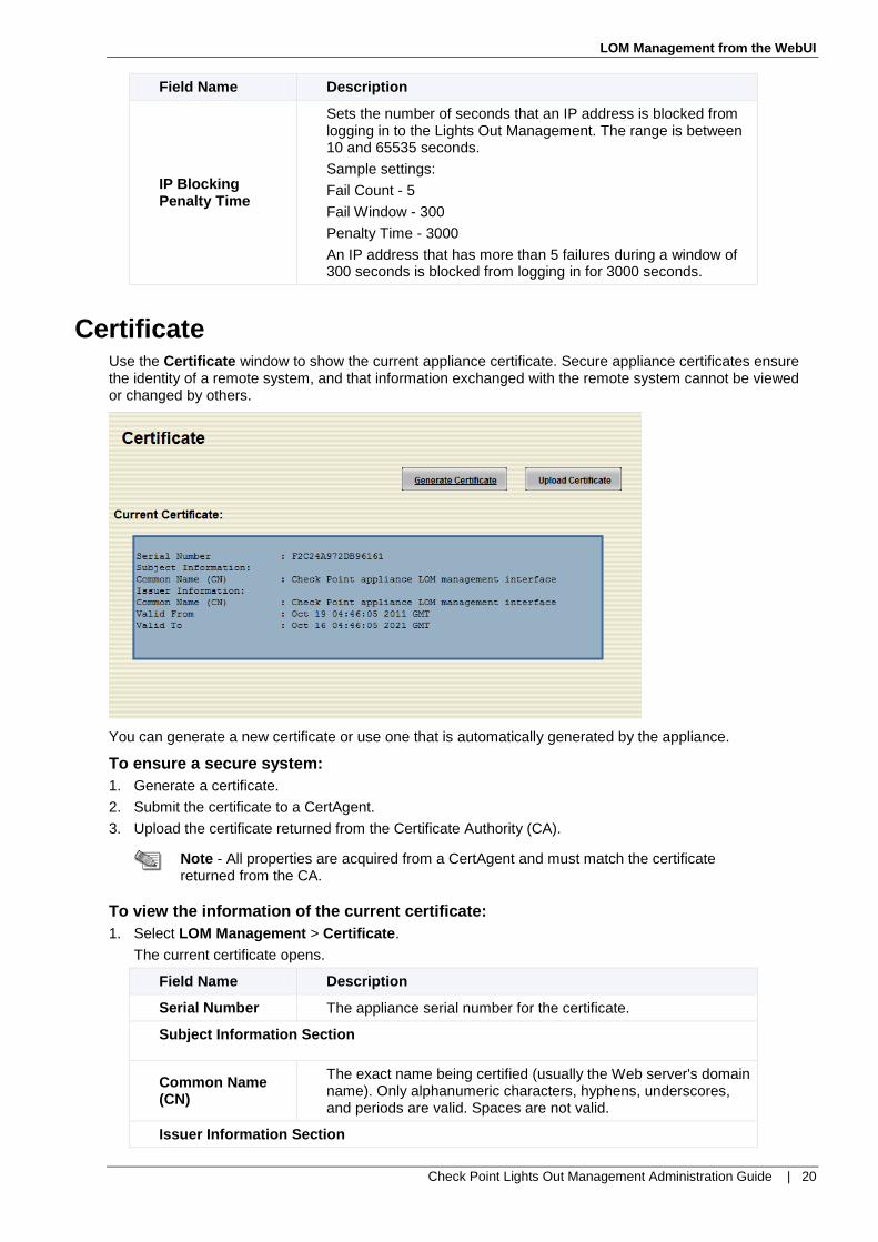
Certificate Use the Certificate window to show the current appliance certificate. Secure appliance certificates ensure the identity of a remote system, and that information exchanged with the remote system cannot be viewed or changed by others.
You can generate a new certificate or use one that is automatically generated by the appliance.
To ensure a secure system:
1. Generate a certificate.
2. Submit the certificate to a CertAgent.
3. Upload the certificate returned from the Certificate Authority (CA).
Note - All properties are acquired from a CertAgent and must match the certificate returned from the CA.
To view the information of the current certificate:
1. Select LOM Management > Certificate.
The current certificate opens.
Field Name Description
Serial Number The appliance serial number for the certificate.
Subject Information Section
Common Name (CN)
The exact name being certified (usually the Web server's domain name). Only alphanumeric characters, hyphens, underscores, and periods are valid. Spaces are not valid.
Issuer Information Section

LOM Management from the WebUI
Check Point Lights Out Management Administration Guide | 21
Field Name Description
Common Name (CN)
Name of the CertAgent. Only alphanumeric characters, hyphens, underscores, and periods are valid.
Valid From Starting date of the certification.
Valid To Date the certificate expires.
Users Use the Users window to configure the settings and privileges for the Lights Out Management users. For more information about user privileges, see Users and Privileges (on page 6).
To view user information and privileges:
Select LOM Management > Users.
The Users window opens.
Field Name Description
User ID User ID number.
State Shows which users are Enabled to log in to the Lights Out Management.
User Name Login name of the user.
User Role Assigned role of each user.

LOM Management from the WebUI
Check Point Lights Out Management Administration Guide | 22
Configuring Users
Use the User Configuration window to modify the settings of a user.
To configure a user:
1. From the Users window, click the number of a user ID.
The User Configuration window opens.
2. Configure information and privileges of the user.
3. Modify the password (when necessary):
a) Select Change Password.
b) Enter a new password in the New Password field.
c) Re-enter the password in the Confirm New Password field to confirm.
4. Click Apply Changes.
Field Name Description
General
User ID One of 16 user IDs.
Enable User When selected, this user can access the Lights Out Management.
User Name A maximum of 16 characters. Only use alphanumeric, underscore, and dash characters.
Change Password When selected, the password can be changed.
New Password Enter a new password with a maximum of 16 characters.
Confirm New Password
Enter the new password again.
User Privileges Section
User Role Select the role of the user (Administrator, Operator, or User).
LOM LAN Privilege Select the role of the LOM LAN Privilege (Administrator, Operator, User, or None).
LOM Serial Privilege
Select the role of the LOM Serial Privilege (Administrator, Operator, User, or None).
Enable Serial Over LAN
This feature will be implemented in the near future.

LOM Management from the WebUI
Check Point Lights Out Management Administration Guide | 23
Web Use the Web window to view the services parameters and configure the WebUI settings.
To configure the settings for the WebUI:
1. Select LOM Management > Web. The Web window opens.
2. Configure the WebUI settings.
3. Click Apply Changes.
Field Name Description
HTTP Port Number Use this HTTP port to connect to the WebUI.
HTTPS Port Number
Use this HTTPS port to connect to the WebUI.
Timeout Maximum time that the WebUI can remain idle (from 60 to 10,800 seconds) before the user is logged out.
Max Sessions Configure the maximum number of simultaneous sessions.
Active Sessions Shows the number of active sessions.
Sessions Use the Sessions window to close an active session for another user that is logged in to Lights Out Management. The window also shows all the users that are logged in with active sessions.
To close an open session:
1. Select LOM Management > Sessions.

LOM Management from the WebUI
Check Point Lights Out Management Administration Guide | 24
The Sessions window opens.
2. Click the icon in the Kill column.
The open session is closed.
LDAP Configuration Use the LDAP Configuration Page to connect Lights Out Management users to the LDAP database.
Field Name Description
Enable LDAP Enables LDAP based authentication.
Enable Encryption for LDAP client
Enables encryption for the LDAP client. This determines if
ldap:// or ldaps://, or StartTLS should be used.
Use DNS to find servers
Defines DNS as the method to find LDAP servers.
Domain Source Select how to obtain the domain name used for the DNS SRV request (Use Domain from Login, Use Configured Search Domain, or Try Login Domain).
Domain Name for DNS SVR request
Domain name to use for a DNS SRV request in the
domain.com format.
Service Name Service name for DNS SRV requests.
Domain Controller 1 Host name or IP Address of the first configured domain controller.
Domain Controller 1's Port
Port number of the first configured domain controller.
Domain Controller 2 Host name or IP Address of the second configured domain controller.

LOM Management from the WebUI
Check Point Lights Out Management Administration Guide | 25
Field Name Description
Domain Controller 2's Port
Port number of the second configured domain controller.
Domain Controller 3 Host name or IP Address of the third configured domain controller.
Domain Controller 3's Port
Port number of the third configured domain controller.
Base Domain Name Enter in dc=domain, dc=com format for AD and
dc=domain.com format for e-Directory.
UID Search Object value
The attribute name used to query for the user object:
sAMAccountName, for AD or UID, for Novell or e-Directory.
Group Filter Role group names that are queried.
Binding Method Select the binding method: anonymous bind, Configured Credentials, or Login Credentials.
Client ID used with CC binding
The client ID used with the Configured Credentials binding method.
Client Password used with CC binding
The client password used with the Configured Credentials binding method.
Group ID Attribute Queries the user for group membership.
Attribute to query permission in group
Queries the user or group object for permissions in the group.
Querying Multiple Groups
You can use the Group Filter field to query multiple LDAP groups. Enter the CN (common name) for each group with a colon in between the CNs. You can also use wildcards in the Group Filter field.
Sample Group Filter Query
Queries that use these LDAP CNs - GroupA, GroupB, and GroupC.
GroupA:GroupB - Specifies GroupA and GroupB in the filter.
GroupA:GroupB:GroupC - Specifies all three groups in the filter.
Group* - Uses the * wildcard to specify all groups in the filter.
Creating New User (Linux)
Select one attribute as the privilege flag for the user accounts. You must configure the privilege flag to allow the user account to log in to the Lights Out Management WebUI. For more information on Lights Out Management privileges, see Users and Privileges (on page 6).
To create a new user account in an LDAP Linux server:
1. Edit the LDIF file for the new user.
In this example, the description attribute is used as the user account privilege flag.
dn: uid=ldaptest,ou=People,dc=swrd,dc=lan uid: ldaptest cn: LDAP User objectClass: account objectClass: posixAccount objectClass: top objectClass: shadowAccount userPassword: {SSHA}5Wucw4czdFtB2cDRjy4sTAMpSsiyeGDT shadowLastChange: 15204 loginShell: /bin/bash uidNumber: 5500 gidNumber: 55

LOM Management from the WebUI
Check Point Lights Out Management Administration Guide | 26
homeDirectory: /home/ldaptest gecos: LDAP User description: 111111111
2. Run this command and add the user account into LDAP server.
[root@dev3 ~]# ldapadd -x -W -D "cn=Manager,dc=swrd,dc=lan" -f
ldaptest.ldif
3. Enter the LDAP password.
4. Add new entry uid=ldaptest,ou=People,dc=swrd,dc=lan. Configure the privilege level for the
user.
PRIVILEGE_ADMIN = 111111111 PRIVILEGE_OPERATOR = 110011111 PRIVILEGE_READONLY = 000000001 PRIVILEGE_NONE = 000000000
For example, to configure Administrator privileges use this privilege flag: description: 111111111
5. In the Lights Out Management WebUI, select LOM Management > LDAP.
The LDAP Configuration Page window opens.
6. In Attribute to query permission in group, enter the attribute that is used for the user account privilege.
7. Click Apply Changes.
Creating New User (Windows)
Select one attribute as the privilege flag for the user accounts. You must configure the privilege flag to allow the user account to log in to the Lights Out Management WebUI. For more information on Lights Out Management privileges, see Users and Privileges (on page 6).
To create a new user account in an LDAP Windows server:
1. On the Windows server, open the Properties for the user account.
2. In Description, enter the privilege level for the user.
111111111 - Administrator
110011111 - Operator
000000001 - Read only
000000000 - None

LOM Management from the WebUI
Check Point Lights Out Management Administration Guide | 27
3. In the Lights Out Management WebUI, select LOM Management > LDAP.
The LDAP Configuration Page window opens.
4. In Attribute to query permission in group, enter description.
5. Click Apply Changes.

LOM Management from the WebUI
Check Point Lights Out Management Administration Guide | 28
RADIUS In the RADIUS window, you can change RADIUS configuration settings. RADIUS supplies user authentication from a remote database.
Important - Only FreeRadius is supported. Other Radius servers might be supported in the future.
To configure RADIUS:
1. On the RADIUS server, set Reply-Message for privilege to each user in the User file. Otherwise, the
user account is rejected by LOM WebUI.
Format is: Reply-Message = "privilege=LEVEL"
The privilege levels are:
PRIVILEGE_ADMIN = 0x1ff,
PRIVILEGE_OPERATOR = 0x19f,
PRIVILEGE_READONLY = 0x001,
PRIVILEGE_NONE = 0x000
For example: Reply-Message = "privilege=0x1ff"
2. Set the secret and share it with LOM WebUI (maximum of 16 characters, no spaces).
For example: In clients.conf, change the secret line to: Secret = testing123
3. In the Lights Out Management WebUI, select LOM Management > RADIUS.
The RADIUS window opens.
4. Configure the RADIUS settings.
5. Click Apply Changes.
Field Name Description
Enable RADIUS When selected, enables RADIUS based authentication.
RADIUS Server IP IPv4 address for the RADIUS server.
RADIUS Port Port of the RADIUS server (default 1812).
RADIUS Secret Case-sensitive text string that was created in step 2 (default
secret).
RADIUS Time out Number of seconds, before the router retransmits a RADIUS
packet to an authentication or accounting server (default 1).

LOM Management from the WebUI
Check Point Lights Out Management Administration Guide | 29
Utilities Use the Utilities window to reset and restart the LOM card. You can:
Restart the LOM card.
Reset the LOM card to factory default settings.
To control the Lights Out Management:
1. Select LOM Management > Utilities. The Utilities window opens.
2. Click Reboot to restart the Lights Out Management.
3. Click Factory Default to reset the Lights Out Management to the factory default settings.

Check Point Lights Out Management Administration Guide | 30
Appendix A
Resetting the LOM Card through the BIOS
If for any reason you cannot log in to the Lights Out Management WebUI, it is necessary to enter the appliance BIOS. You can use the BIOS Setup Utility to reset the LOM card to reset to the factory default settings. Contact the Check Point Support Center (http://supportcenter.checkpoint.com) for more information.