charge state separator spes conceptual design report
TRANSCRIPT

SPES Conceptual Design Report
5 MeV
100 MeV
Be converter
Ion source
Isotope separator
Charge breeder
SRFQ
Charge state separator
High resolution spectrometer
RFQ
BNCTSource TRIPS U target
ISCL
TECHNICAL COMMITTEEA. Pisent (Technical Coordinator)M. Comunian (Injector and Normal
Conducting Driver Linac)A. Facco (Superconducting Driver Linac)L. Tecchio (Production of Exotic Beams)A. Lombardi (Reacceleration of Exotic
Beams)P. Favaron (Civil Engineering,
Infrastructure and Safety)G. Bisoffi (Costs and Schedule)
ALPIExp.
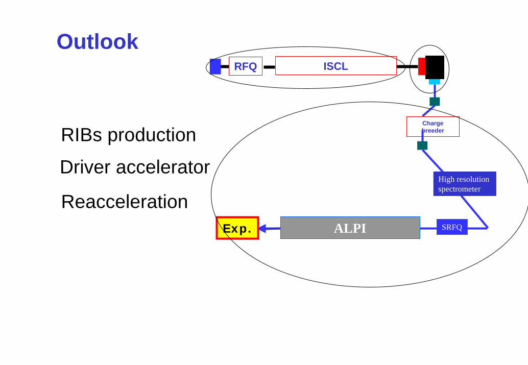
RIBs production
ISCLRFQ
Driver accelerator
Charge breeder
ALPIExp. SRFQ
High resolution spectrometer
Reacceleration
Outlook

Production of neutron reach RIBs in SPES
Beryllium converter
Graphite matrix
UCx target rods
100 MeV, 1mA
proton beam
• Fission induced by fast neutrons• 3 1013 fissions per second.• The p beam power (~ 100 kW) is dissipated in the first target
(converter), while the second target (production target) only withstands the fission power (few kW).
• The production target consists of 238U, in the UCx form. • The (p/n) converter is a thick Be target

p energy
0
0.1
0.2
0.3
0.4
0.5
0.6
0 50 100 150proton energy [MeV]
neut
ron/
prot
on
0.0
2.0
4.0
6.0
8.0
10.0
12.0
rang
e of
p in
Be
[cm
]n
per p
per
trg
et
thic
knes
s [m
-1]
neutron/p
range of p in Be
n/p/m
a
Number of neutrons (above 2 MeV) produced for each proton in thewhole solid angle

Neutron production@different beam powerneutron production
0.00E+00
5.00E+14
1.00E+15
1.50E+15
2.00E+15
2.50E+15
3.00E+15
0 50 100 150Proton energy [MeV]
neut
rons
/sbeam 50 kWbeam 100 kWbeam 150 kW
Flux of neutrons (above 2 MeV) in the whole solid angle for a thick beryllium target as function of p energy.

1.0E-02
1.0E-01
1.0E+00
1.0E+01
1.0E+02
1.0E+03
1.0E+04
1.0E+05
0 10 20 30 40 50 60 70 80 90 100
Neutron energy [MeV]
Yiel
d(1
.6E-
7)/S
r per
inci
dent
pro
ton]
0 < α < 30
30 < α < 60
60 < α < 90
Beryllium converter
Graphite matrix
UCx target rods
100 MeV, 1mA
proton beam
[
• Production target 4 kg UCx , nuclear graphite containing UCx rods (φ= 10 mm, δ = 2.5 g cm-2) uniformly distributed.
• A tungsten container encapsulates the target that can be heated to high temperatures (2000-25000C).
• This latter is connected by a tube to an ion source and both stand to a potential of 60 kV, respect the ground.
• The calculated total fission rate is about 3 x 10¹³/s
n spectrum (100 MeV p on thick Be target)

Fragments produced by each proton(in 4 kg of Ucx)
Sn132
The nominal beam is of 1.7 x 10¹⁶ p/s.

Fission mass distribution for 100 MeV, 1 mAproton beam on beryllium converter and 4 kg
UCx production target
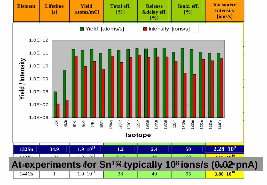
Element Lifetime [s]
Yield [atoms/mC]
Total eff. [%]
Release &delay eff.
[%]
Ioniz. eff. [%]
Ion source Intensity [ions/s]
68Ni 29 1.0 108 12 30 40 1.20 107 78Zn 1.47 5.0 109 0.048 4.8 10 2.40 107 91Kr 8.6 2.0 1011 28.8 72 40 5.76 1010 94Kr 0.2 1.5 1011 64 16 40 9.60 109 97Rb 0.17 2.0 1011 11.4 12 95 2.28 1010 105Zr 0.6 1.0 1011 6 12 50 6.00 109 120Ag 1.23 2.0 1011 30 60 50 6.00 1010 120Pd 3.91 1.5 1011 12.5 50 25 1.88 1010 123Cd 2.09 2.0 1011 24 60 40 4.80 1010 125In 2.36 2.3 1011 32 80 40 7.36 1010 128Sn 59 m 2.1 1011 21.2 40 53 4.45 1010 129Sn 2,4 m 2.5 1011 21.2 40 53 5.30 1010 130Sn 3,7 m 2.5 1011 21.2 40 53 5.30 1010 130In 0.29 1.2 1011 20 50 40 2.40 1010 131Sn 39 2.3 1011 1.2 2.4 50 2.76 109 132Sn 34.9 1.9 1011 1.2 2.4 50 2.28 109 142Xe 1.24 1.2 1011 26.4 44 60 3.17 1010
144Cs 1 1.0 1011 38 40 95 3.80 1010
1.0E+06
1.0E+07
1.0E+08
1.0E+09
1.0E+10
1.0E+11
1.0E+12
68Ni
78Zn
91Kr
94Kr
97Rb
105Z
r
120A
g
120P
d
123C
d
125In
128S
n
129S
n
130S
n
130In
131S
n
132S
n
142X
e
144X
e
144C
s
Isotope
Yield
/ Int
ensit
yYield [atoms/s] Intensity [ions/s]
144Xe 1.15 1.0 1011 26.4 44 60 2.64 1010 At experiments for Sn132 typically 108 ions/s (0.02 pnA)

10 MeV 30 mA
L=90
cm
Be converter
300 kW water cooledto be prototyped

Thermal stress calculations(10 MeV, 30 mA)
Maximum thermo-mechanical stress [107 Pa]
σm Be σθ Be σult Be / σfl Be σm Fe σθ Fe σult Fe / σfl Fe 8.76 10.96 27 - 37 / 25.5 12.71 15.90 32.4 / 20.5

R&D for C13 rotating target
R&D program for the production of C13 with graphyte mechanical properties

SPES block diagram
5 MeV/u 100 MeV
BNCT
Be converter
U target
ISCLRFQ
Source (p)
Ion sources
Isotope separatorCharge breeder
High resolution spectrometer
ALPIExp. RFQ
Charge state separator
Source A/q<3
RFQ ISCL
Non fission targetExp.
•A/q<3 (~100MeV/q):fusion-evaporation or multinucleon transfer reactions. •deuterons increased production of neutrons (*2 on the whole solid angle, * 8 in the forward direction) getting to 1014 Fission/s.•with d is much more difficult the linac operation (activation of the structure including the RFQ).•this high intensity ion beam can be directly used by experiments.
Beside fast fission, p for direct reactions

The driver linacThe main linac parameters are: • Beam energy: ∼100 MeV• Beam current : 5 mA (like Eurisol driver)• rf installed for 3 mA• Duty cycle: 100% (cw), compatible with pulsed operation• Beam losses below 1 W/m• RF frequency: 352 MHz• A/q≤3 ions accelerated
• The driver construction will include two stages. – In the first stage the proton injector and the main linac will be built. – In the second stage, the ion injector will be built.
RFQRFQ 2gaps
176 MHzcavity number2 gaps
Main linac 352 MHz4gaps

TRIPS TRASCO source developed at LNSRF off resonance, up to 80 mA

coupling cells
wave guide RF loop
7.13 mtechn. model
tuners wave guidevacuum portsRF loop
TRASCO RFQ (5 MeV, 30 mA)

Wave guides(1 LEP klystron and 8 power loops)
RFQ
beam
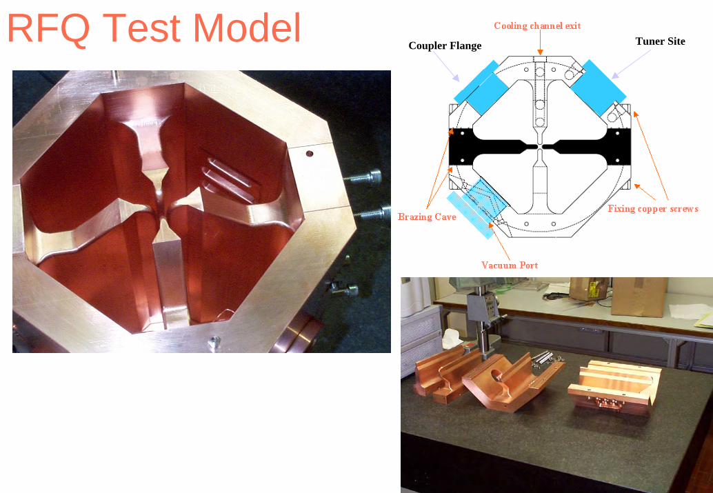
RFQ Test ModelCoupler Flange Tuner Site
coupler

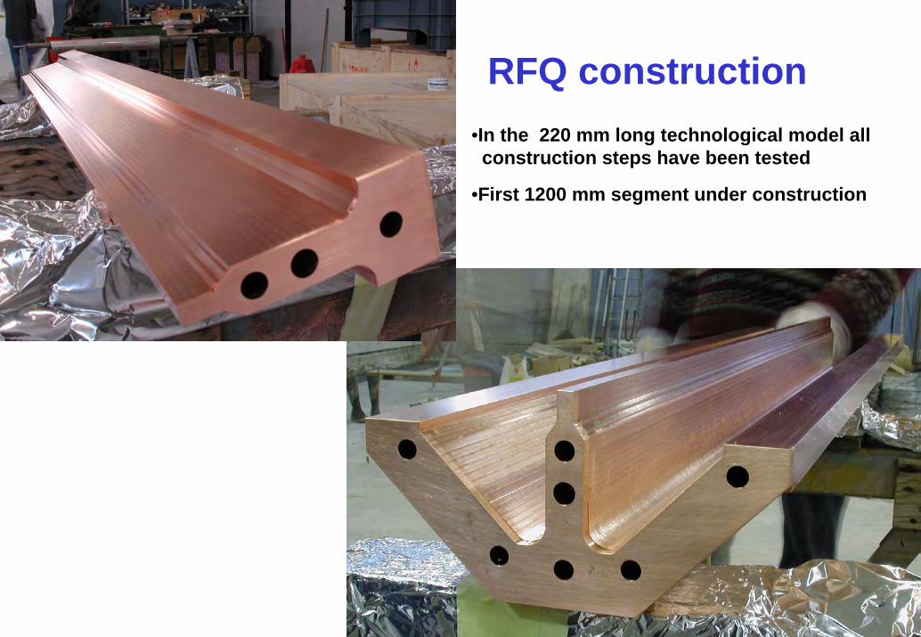
•In the 220 mm long technological model all construction steps have been tested
•First 1200 mm segment under construction
RFQ construction
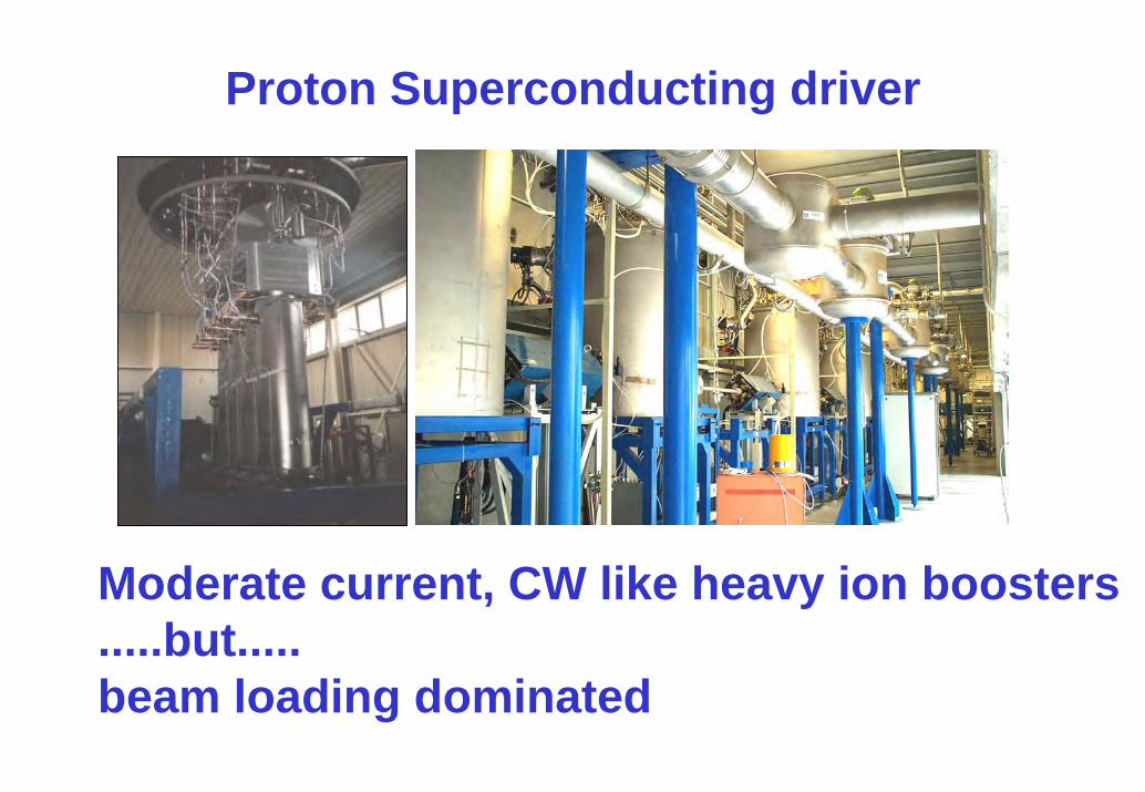
Proton Superconducting driver
Moderate current, CW like heavy ion boosters.....but.....beam loading dominated

352 MHz solid state RF amplifiers2.5 kW RF Amplifier
0%
10%
20%
30%
40%
50%
60%
0 500 1000 1500 2000 2500 3000
RF out power [W]
Eff
icie
ncy
0
5
10
15
20
25
30
Gai
n EfficGain
330 W basic unit2.5 kW prototype

100 MeV TRASCO linac
•4 βλ
•Cryostat (4.5 K)
•280 mm •100 •mm
•140 mm
•50 mm
•F •D
•…
•4 βλ
•tuning
•Supercond•=40 mm
•4 βλ
•Reentrant cavity•Cryostat (4.5 K)
•280 mm •100 •mm
•140 mm
•50 mm
•F •D
•280 mm •100 •mm
•140 mm
•50 mm
•F •D
•…
•Superferric qudrupole

Driver structure (Φs=-300)
Main Linac transit time factor for protons
0.0000.200
0.4000.600
0.8001.000
0 20 40 60 80 100 120cavity number
TTF
025
5075
100125
E (M
eV)
TTFEnergy [MeV]
RFQ 4gaps 2 gaps
0.12 0.17 0.25 0.31β0=

Cavities(352 MHz)
Cavity type 4-gap 4-gap HWR HWR units
β0 0.12 0.17 0.25 0.31
n. of gap 4 4 2 2Ep/ Ea ∼3. ∼3. ∼4 ∼4
Hp/Ea 102 87 95 106 Gauss/(MV/m)
Rs × Q 45 62 54 66 Ω
Eff. length 0.2 0.28 0.18 0.214 m
Design Ea 6 6 6 6 MV/m
Design energy gain 1.2 1.7 1.08 1.284 MeV/q
n. required 6 6 32 48

RFQ Energy Range 0.023 ÷ 1.7 MeV/uFrequency 176 MHzBeam Current 3 mATransmission 96 %Length 7.2 m (4.2 λ)Approx. RF power 500 kWParameters of the SPES ion injector linacbeam energy 18.5 MeVBeam current 3 mANumber of cavities 18Approx. Length of the ISCL 7.5 mavg. cryogenic power in operatio 217 Wtotal AC power in operation 201 kW
RFQ to be developed cw!Able to resist d induced activation!
LNL for CERN, 1994
cavity numberRFQ 2 gaps2gaps
176 MHz
Ion Linac A/q<3
4gaps
Main linac 352 MHz

Linac acceptanceinjection 1.7 MeV/u
0
20
40
60
80
100
120
0 1 2 3 4
M/q
Final
Ener
gy
f inal MeV/q
final MeV/u
RFQ 2gaps
176 MHzcavity number2 gaps4gaps
Main linac 352 MHz
Reacceleration with ALPI

SPES lay-out
100
met
ers
RF and services
Driver Linac
BNCT treatment
isobar separation
RIBs target Hot Cells
Existing TANDEM-ALPI-PIAVE complex
Reaccelerator RFQs
Ion source
breeder
Ion trap area
S
WE
N
RIBs production
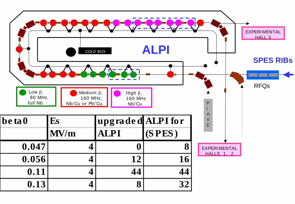
PIAVE
COLD BOX
Medium β,160 MHz,
Nb/Cu or Pb/Cu.
Low β, 80 MHz,
full Nb.
High β,160 MHz Nb/Cu.
ALPI
RFQs
SRFQs
Low β QWR (bulk Nb)
High β QWR (Nb/Cu)
be ta0 Es upgrade d ALPI forMV/m ALPI (S PES )
0.047 4 0 80.056 4 12 16
0.11 4 44 440.13 4 8 32
EXPERIMENTALHALL 3
SPES RIBs
EXPERIMENTALHALLS 1, 2

Injector• Charge breeder (ECR or EBIS): from results of
EU RTD Network a charge state +18 for Sn132 is feasable.
• High resolution separator, either:– ISAC like magnetic structure before the breeder– Mixed magnetic TOF using the long transfer lines
• RFQ will accept A/q=10, three SRFQ• Only the first RFQ needs important R&D (and
could be normal conducting)
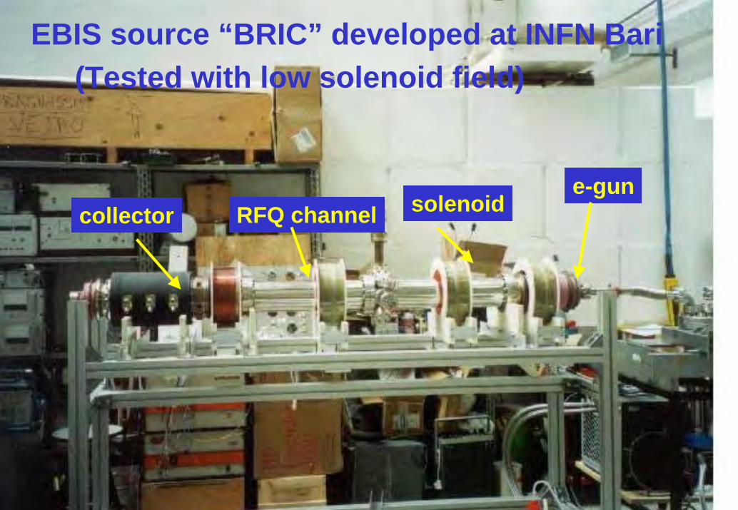
collector RFQ channele-gun
EBIS source “BRIC” developed at INFN Bari(Tested with low solenoid field)
solenoid

transit time factor
0.000.10
0.200.30
0.400.500.60
0.700.80
0.901.00
0 20 40 60 80 100 120
cavity number
TTF
-1'000
1'000
3'000
5'000
7'000
9'000
11'000
13'000
15'000
TTFEnergy [keV/u]
Sn132+18
COLD BOX
Sn132+18 in ALPI
(up to 9.6 MeV/u)

Sn132+18 in ALPI with stripper(up to 15.7 MeV/u)
transit time factor
0.000.100.20
0.300.400.500.600.70
0.800.901.00
0 20 40 60 80 100 120
cavity number
TTF
-1'000
1'000
3'000
5'000
7'000
9'000
11'000
13'000
15'000
TTFEnergy [keV/u]
Sn132+18 Sn132
+38stripper
COLD BOX

SPES building

SPES Building
100
met
ers
RF and services
Driver Linac
BNCT treatment
isobar separation
RIBs target Hot Cells
Existing TANDEM-ALPI-PIAVE complex
Reaccelerator RFQs
Ion source
breeder
Ion trap area
S
WE
N
RIBs production

SPES Building•A sled with light external structures, but with a floor sitting on a thick concrete bed in the regions where ionizing radiation is produced, so to exclude water contamination; •The floor must be able to sustain a thick shielding walls, with the possibility to add concrete blocks. •The building has to maintain the alignment of linac and beam lines.•In a preliminary study it has been checked the feasibility of this solution, using in the central part of the building a linac tunnel 8 m wide and 4.6 m height, an 8 m thick concrete bed below the linac tunnel, 6 m lateral shielding and 5 m concrete roof.•A core boring of the ground showed various layers of clay, silt and sand, with the water layer at –2.5 m from ground level. A specific proposal for the construction of the building under these geological conditions has been done.

TRIUMF solution

Shielding the target area (100 MeV 30 mA)

Conclusions
• The facility will reach its physics goal making the maximum use of
–existing installations
–developed accelerators and other high technology components
–out come of already launched R&D programs
• In this sense, the need for R&D is minimized.

R&DIn the immediate future, the R&D needs to be intensified, so to arrive to engineered
and proven systems for all the components of SPES. The most relevant points are:
1. Completion of the RFQ
2. Construction of a prototype of Be converter (and possibly beam measurement atPSI) and development of C13 targets.
3. UCx target development.
4. Construction of a ISCL cryomodule (HWR, ladder cavities) and related RF.
5. Development of the bunching RFQ for the reacceleration.
6. Charge breeder and isobar separation.
7. Waste management and safety.
For ion acceleration there is need for an additional point, namely
8. Development of the 176 MHz RFQ for A/q=3 ions.
These programs have to be implemented, making the best use of the resources ofLNL and of possible synergies with other projects and institutions.