chapter6 temperature measurement 08 v3
TRANSCRIPT
8/8/2019 Chapter6 Temperature Measurement 08 v3
http://slidepdf.com/reader/full/chapter6-temperature-measurement-08-v3 1/36
Topic 1.6 TemperatureTopic 1.6 Temperature-- 11EEB5223/EAB4223 Industrial Automation & Control Systems
Assoc Prof Dr Nordin Saad
Department of Electrical & Electronics Engineering
Universiti Teknologi PETRONAS
Email: [email protected]
Tel: 05-368 7835
Industrial Instrumentation and
Measurements
Temperature
Measurements
8/8/2019 Chapter6 Temperature Measurement 08 v3
http://slidepdf.com/reader/full/chapter6-temperature-measurement-08-v3 2/36
Topic 1.6 TemperatureTopic 1.6 Temperature-- 22EEB5223/EAB4223 Industrial Automation & Control Systems
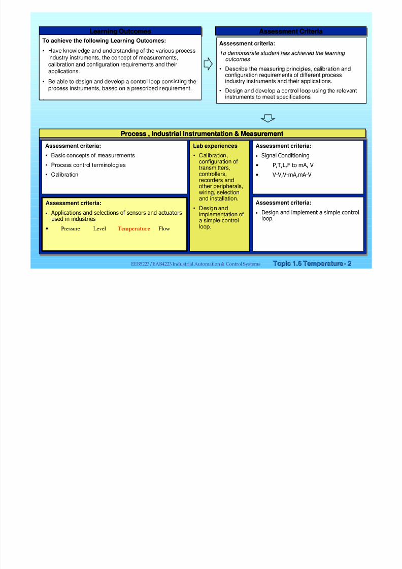
Learning Outcomes
Learning OutcomesLearning Outcomes
To achieve the following Learning Outcomes:
• Have knowledge and understanding of the various process
industry instruments, the concept of measurements,calibration and configuration requirements and their
applications.
• Be able to design and develop a control loop consisting theprocess instruments, based on a prescribed requirement.
.
Assessment Criteria
Assessment CriteriaAssessment Criteria
Assessment criteria:
To demonstrate student has achieved the learning outcomes
• Describe the measuring principles, calibration andconfiguration requirements of different processindustry instruments and their applications.
• Design and develop a control loop using the relevantinstruments to meet specifications
Assessment criteria:
• Basic concepts of measurements
• Process control terminologies
• Calibration
Lab experiences
• Calibration,configuration oftransmitters,controllers,recorders andother peripherals,wiring, selectionand installation.
• Design andimplementation ofa simple controlloop.
Assessment criteria:
• Signal Conditioning
• P,T,L,F to mA, V
• V-V,V-mA,mA-V
Assessment criteria:
• Applications and selections of sensors and actuatorsused in industries
• Pressure Level Temperature Flow
Assessment criteria:
• Design and implement a simple controlloop.
Process , Industrial Instrumentation & Measurement
Process , Industrial Instrumentation & MeasurementProcess , Industrial Instrumentation & Measurement

8/8/2019 Chapter6 Temperature Measurement 08 v3
http://slidepdf.com/reader/full/chapter6-temperature-measurement-08-v3 3/36
Topic 1.6 TemperatureTopic 1.6 Temperature-- 33EEB5223/EAB4223 Industrial Automation & Control Systems
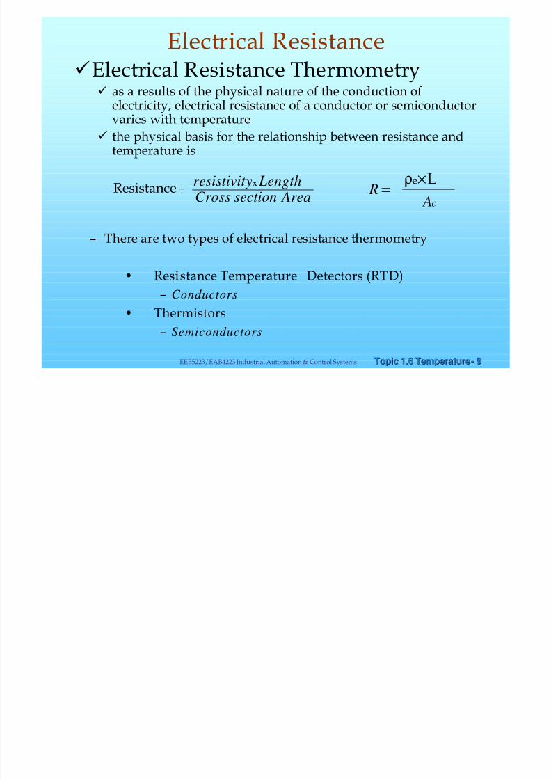
Types of temperature measurements
– Thermometry based on thermal expansion
– Electrical Resistance Thermometry
– Thermoelectric
Types of Temperature measurements

8/8/2019 Chapter6 Temperature Measurement 08 v3
http://slidepdf.com/reader/full/chapter6-temperature-measurement-08-v3 4/36
Topic 1.6 TemperatureTopic 1.6 Temperature-- 44EEB5223/EAB4223 Industrial Automation & Control Systems
üThermometry based on thermalexpansion
• Liquid in Glass Thermometers
• Bimetallic Thermometers
Thermal expansion

8/8/2019 Chapter6 Temperature Measurement 08 v3
http://slidepdf.com/reader/full/chapter6-temperature-measurement-08-v3 5/36
Topic 1.6 TemperatureTopic 1.6 Temperature-- 55EEB5223/EAB4223 Industrial Automation & Control Systems
• Liquid in Glass Thermometers
– measures temperature by virtue of the thermalexpansion of a liquid.
– Change of fluid to cause a detectable rise of theliquid in the stem of the thermometer
– level of the liquid in the capillary is anindication of the temperature
Thermal expansion

8/8/2019 Chapter6 Temperature Measurement 08 v3
http://slidepdf.com/reader/full/chapter6-temperature-measurement-08-v3 6/36
Topic 1.6 TemperatureTopic 1.6 Temperature-- 66EEB5223/EAB4223 Industrial Automation & Control Systems
• Complete immersion thermometer– the entire thermometer is immersed in
the calibrating temperatureenvironment
• Total immersion thermometer– the thermometer is immersed in thecalibrating temperature environmentup to the liquid level in the capillary
• Partial immersion thermometer– the thermometer is immersed to a
predetermined level in the calibratingenvironment
Thermal expansion
8/8/2019 Chapter6 Temperature Measurement 08 v3
http://slidepdf.com/reader/full/chapter6-temperature-measurement-08-v3 7/36
Topic 1.6 TemperatureTopic 1.6 Temperature-- 77EEB5223/EAB4223 Industrial Automation & Control Systems
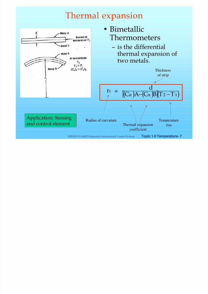
• Bimetallic
Thermometers– is the differential
thermal expansion oftwo metals.
( ) ( )[ ]( )12 TTBCACdrc
−− ααα
Thickness
of strip
Radius of curvature Temperature
riseThermal expansion
coefficient
Application: Sensingand control element
Thermal expansion
8/8/2019 Chapter6 Temperature Measurement 08 v3
http://slidepdf.com/reader/full/chapter6-temperature-measurement-08-v3 8/36
Topic 1.6 TemperatureTopic 1.6 Temperature-- 88EEB5223/EAB4223 Industrial Automation & Control Systems
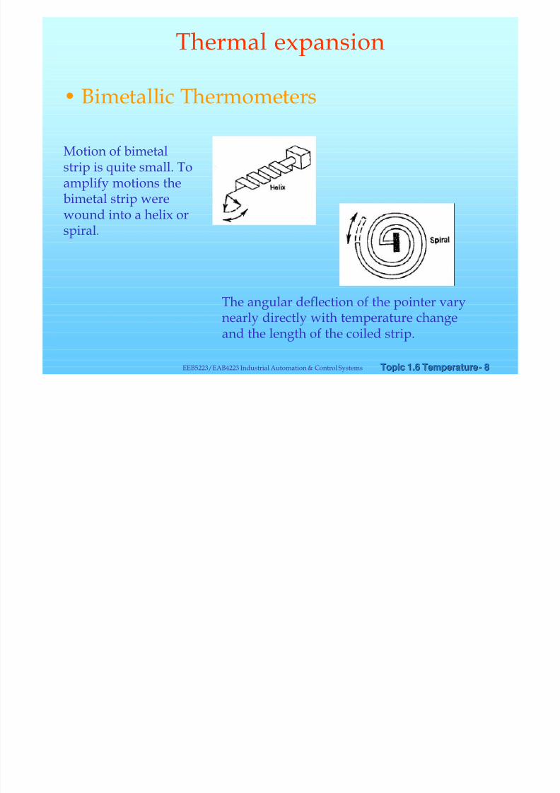
• Bimetallic Thermometers
The angular deflection of the pointer varynearly directly with temperature changeand the length of the coiled strip.
Motion of bimetalstrip is quite small. Toamplify motions the
bimetal strip werewound into a helix orspiral.
Thermal expansion
8/8/2019 Chapter6 Temperature Measurement 08 v3
http://slidepdf.com/reader/full/chapter6-temperature-measurement-08-v3 9/36

8/8/2019 Chapter6 Temperature Measurement 08 v3
http://slidepdf.com/reader/full/chapter6-temperature-measurement-08-v3 10/36
Topic 1.6 TemperatureTopic 1.6 Temperature-- 1010EEB5223/EAB4223 Industrial Automation & Control Systems
• Resistance Temperature Detectors, RTD
– The sensor is constructed by mounting a metalwire on an insulating support structure
• To eliminate mechanical strains
• To prevent changes in resistance that due toinfluences from the sensor’s environment
– The relationship between temperature andresistance over specific small temperature rangesis linear
Electrical resistance
8/8/2019 Chapter6 Temperature Measurement 08 v3
http://slidepdf.com/reader/full/chapter6-temperature-measurement-08-v3 11/36
Topic 1.6 TemperatureTopic 1.6 Temperature-- 1111EEB5223/EAB4223 Industrial Automation & Control Systems
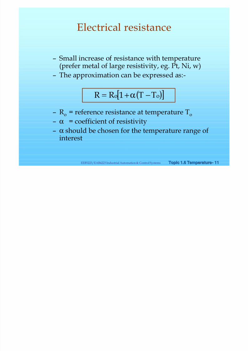
– Small increase of resistance with temperature(prefer metal of large resistivity, eg. Pt, Ni, w)
– The approximation can be expressed as:-
– Ro = reference resistance at temperature To
– α = coefficient of resistivity
– α should be chosen for the temperature range ofinterest
( )[ ]oo TTRR −+= α1
Electrical resistance

8/8/2019 Chapter6 Temperature Measurement 08 v3
http://slidepdf.com/reader/full/chapter6-temperature-measurement-08-v3 12/36
Topic 1.6 TemperatureTopic 1.6 Temperature-- 1212EEB5223/EAB4223 Industrial Automation & Control Systems
• Most common material used is platinum.
Platinum
Copper
Nickel
Balco (70% Nickel,30% Iron)
Tungsten
Electrical resistance
8/8/2019 Chapter6 Temperature Measurement 08 v3
http://slidepdf.com/reader/full/chapter6-temperature-measurement-08-v3 13/36
Topic 1.6 TemperatureTopic 1.6 Temperature-- 1313EEB5223/EAB4223 Industrial Automation & Control Systems
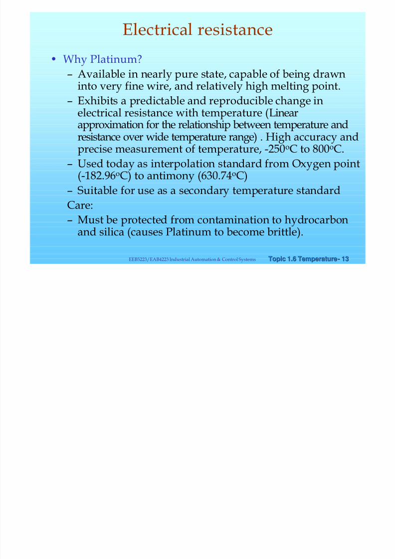
• Why Platinum?
– Available in nearly pure state, capable of being drawninto very fine wire, and relatively high melting point.
– Exhibits a predictable and reproducible change inelectrical resistance with temperature (Linearapproximation for the relationship between temperature and
resistance over wide temperature range) . High accuracy andprecise measurement of temperature, -250oC to 800oC.
– Used today as interpolation standard from Oxygen point(-182.96oC) to antimony (630.74oC)
– Suitable for use as a secondary temperature standard
Care:– Must be protected from contamination to hydrocarbon
and silica (causes Platinum to become brittle).
Electrical resistance

8/8/2019 Chapter6 Temperature Measurement 08 v3
http://slidepdf.com/reader/full/chapter6-temperature-measurement-08-v3 14/36
Topic 1.6 TemperatureTopic 1.6 Temperature-- 1414EEB5223/EAB4223 Industrial Automation & Control Systems
• RTD Resistance Measurement
– RTD must be energized from anexternal power supply (accurateand stable PS).
– W heat st one bridge circuit arecommonly used for thesemeasurements, to obtain a zerobased output signal.
– When greater accuracy are
required three wire and four wirebridge circuits can be used.
Electrical resistance

8/8/2019 Chapter6 Temperature Measurement 08 v3
http://slidepdf.com/reader/full/chapter6-temperature-measurement-08-v3 15/36
Topic 1.6 TemperatureTopic 1.6 Temperature-- 1515EEB5223/EAB4223 Industrial Automation & Control Systems
Metal FilmRTD
-massproduced
-small size
8/8/2019 Chapter6 Temperature Measurement 08 v3
http://slidepdf.com/reader/full/chapter6-temperature-measurement-08-v3 16/36
Topic 1.6 TemperatureTopic 1.6 Temperature-- 1616EEB5223/EAB4223 Industrial Automation & Control Systems
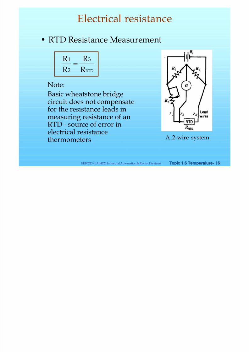
• RTD Resistance Measurement
RTDR
R
R
R 3
2
1=
Note:Basic wheatstone bridgecircuit does not compensatefor the resistance leads inmeasuring resistance of anRTD - source of error in
electrical resistancethermometers A 2-wire system
Electrical resistance

8/8/2019 Chapter6 Temperature Measurement 08 v3
http://slidepdf.com/reader/full/chapter6-temperature-measurement-08-v3 17/36
Topic 1.6 TemperatureTopic 1.6 Temperature-- 1717EEB5223/EAB4223 Industrial Automation & Control Systems
G
R2
R3
RTD=R4
R1
s2
s1
r
r
Power Supply
(Stable andaccurate)
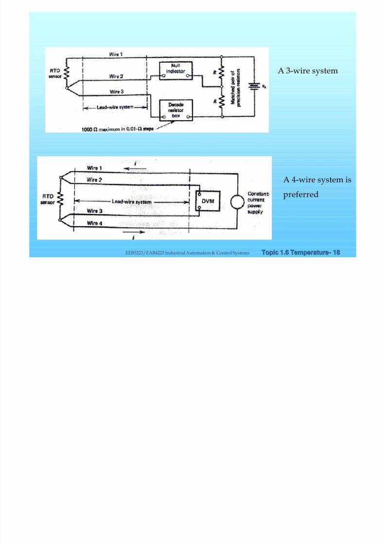
RTD : A 3 wire system
Allows RTD to belocated at a fardistance from
indicatinginstrument
Provides ambienttemperaturecompensation
r s R
r Rs R R −
+
++=
11
3224
))(( Disadvantage: not an accuratetechnique
Electrical resistance
8/8/2019 Chapter6 Temperature Measurement 08 v3
http://slidepdf.com/reader/full/chapter6-temperature-measurement-08-v3 18/36
Topic 1.6 TemperatureTopic 1.6 Temperature-- 1818EEB5223/EAB4223 Industrial Automation & Control Systems
A 4-wire system is
preferred
A 3-wire system
8/8/2019 Chapter6 Temperature Measurement 08 v3
http://slidepdf.com/reader/full/chapter6-temperature-measurement-08-v3 19/36
Topic 1.6 TemperatureTopic 1.6 Temperature-- 1919EEB5223/EAB4223 Industrial Automation & Control Systems
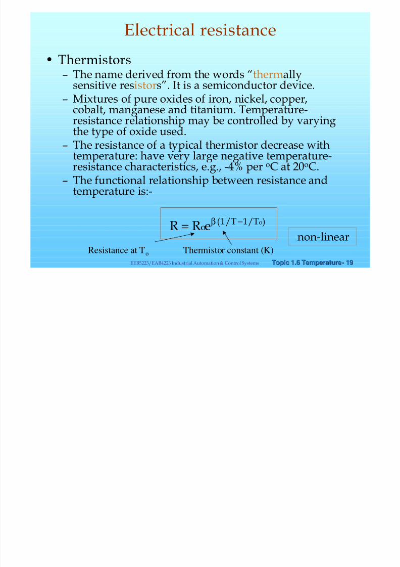
• Thermistors– The name derived from the words “thermally
sensitive resistors”. It is a semiconductor device.– Mixtures of pure oxides of iron, nickel, copper,
cobalt, manganese and titanium. Temperature-resistance relationship may be controlled by varyingthe type of oxide used.
– The resistance of a typical thermistor decrease withtemperature: have very large negative temperature-resistance characteristics, e.g., -4% per oC at 20oC.
– The functional relationship between resistance andtemperature is:-
)/1/1( oTToeRR −= β
non-linearResistance at To Thermistor constant (K)
Electrical resistance
8/8/2019 Chapter6 Temperature Measurement 08 v3
http://slidepdf.com/reader/full/chapter6-temperature-measurement-08-v3 20/36
8/8/2019 Chapter6 Temperature Measurement 08 v3
http://slidepdf.com/reader/full/chapter6-temperature-measurement-08-v3 21/36
Topic 1.6 TemperatureTopic 1.6 Temperature-- 2121EEB5223/EAB4223 Industrial Automation & Control Systems
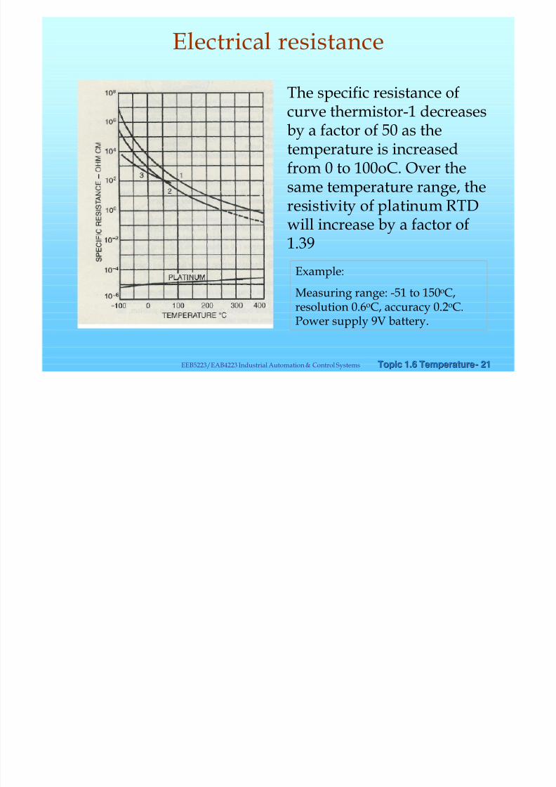
Example:
Measuring range: -51 to 150oC,resolution 0.6oC, accuracy 0.2oC.Power supply 9V battery.
The specific resistance ofcurve thermistor-1 decreasesby a factor of 50 as thetemperature is increasedfrom 0 to 100oC. Over the
same temperature range, theresistivity of platinum RTDwill increase by a factor of1.39
Electrical resistance

8/8/2019 Chapter6 Temperature Measurement 08 v3
http://slidepdf.com/reader/full/chapter6-temperature-measurement-08-v3 22/36
Topic 1.6 TemperatureTopic 1.6 Temperature-- 2222EEB5223/EAB4223 Industrial Automation & Control Systems
– Thermistors generally are used when high sensitivity,ruggedness,fast response times are required e.g. takes
– 15 ms to reach 63% of final Temperature, and 40ms to reach 90%of final Temperature.
– Can also be used in corrosive or abrasive environment
– Suitable for narrow span measurements (due to v. large, non-linear temperature-resistance characteristics).
– For wide temperature span, a wide range of thermistors must beused.
– The zero-power resistance is the resistance value of thethermistor with no flow of electric current.
Electrical resistance
8/8/2019 Chapter6 Temperature Measurement 08 v3
http://slidepdf.com/reader/full/chapter6-temperature-measurement-08-v3 23/36
Topic 1.6 TemperatureTopic 1.6 Temperature-- 2323EEB5223/EAB4223 Industrial Automation & Control Systems
Thermoelectric TemperatureMeasurement
üThe most common method of measuring andcontrolling temperature uses a electrical circuit calleda thermocouple
Thermoelectric
8/8/2019 Chapter6 Temperature Measurement 08 v3
http://slidepdf.com/reader/full/chapter6-temperature-measurement-08-v3 24/36
Topic 1.6 TemperatureTopic 1.6 Temperature-- 2424EEB5223/EAB4223 Industrial Automation & Control Systems
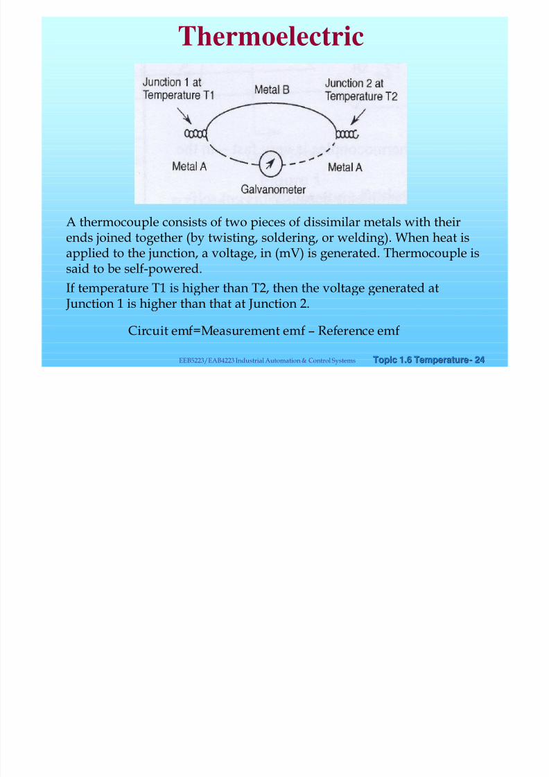
A thermocouple consists of two pieces of dissimilar metals with theirends joined together (by twisting, soldering, or welding). When heat isapplied to the junction, a voltage, in (mV) is generated. Thermocouple issaid to be self-powered.
If temperature T1 is higher than T2, then the voltage generated at Junction 1 is higher than that at Junction 2.
Circuit emf=Measurement emf – Reference emf
Thermoelectric
8/8/2019 Chapter6 Temperature Measurement 08 v3
http://slidepdf.com/reader/full/chapter6-temperature-measurement-08-v3 25/36
Topic 1.6 TemperatureTopic 1.6 Temperature-- 2525EEB5223/EAB4223 Industrial Automation & Control Systems
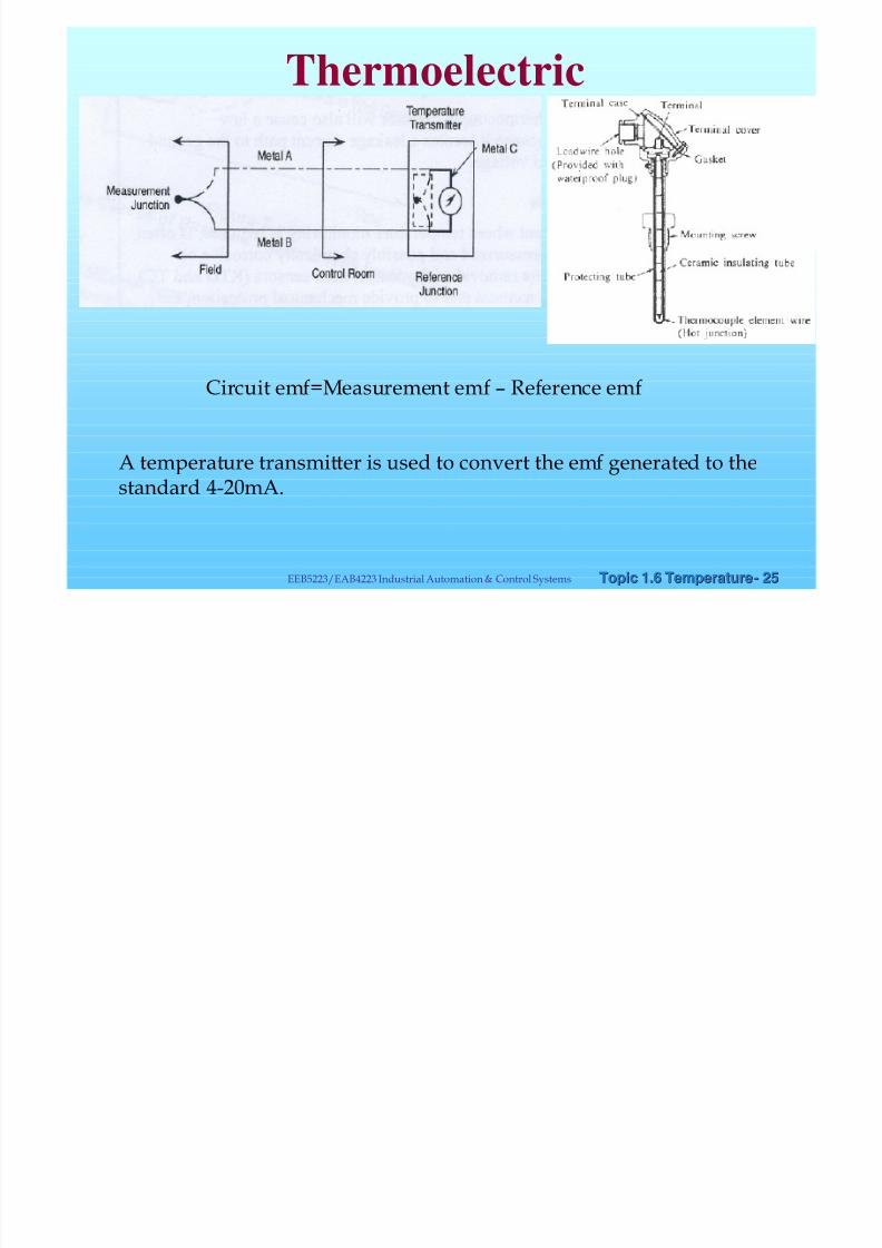
A temperature transmitter is used to convert the emf generated to thestandard 4-20mA.
Circuit emf=Measurement emf – Reference emf
Thermoelectric
8/8/2019 Chapter6 Temperature Measurement 08 v3
http://slidepdf.com/reader/full/chapter6-temperature-measurement-08-v3 26/36
Topic 1.6 TemperatureTopic 1.6 Temperature-- 2626EEB5223/EAB4223 Industrial Automation & Control Systems
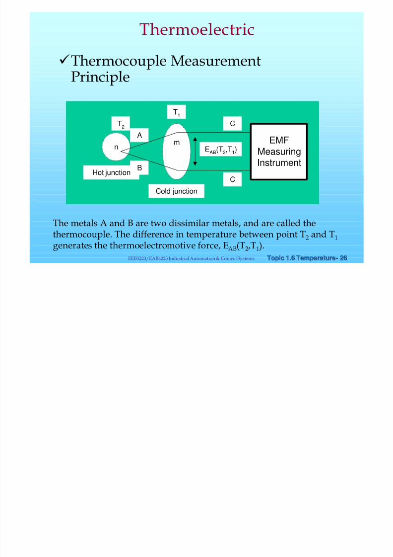
üThermocouple MeasurementPrinciple
n EMFMeasuring
Instrument
m
Cold junction
Hot junction
C
C
A
B
T1
T2
EAB(T2,T1)
The metals A and B are two dissimilar metals, and are called thethermocouple. The difference in temperature between point T2 and T1
generates the thermoelectromotive force, EAB(T2,T1).
Thermoelectric

8/8/2019 Chapter6 Temperature Measurement 08 v3
http://slidepdf.com/reader/full/chapter6-temperature-measurement-08-v3 27/36
Topic 1.6 TemperatureTopic 1.6 Temperature-- 2727EEB5223/EAB4223 Industrial Automation & Control Systems
Thermo-couple EMF graph
Reference Thermoelectromotive Force Table
Type: J Unit: lV
emp.
oC)
0 -10 -20 -30 -40 -50 -60 -70 -80 -90 Temp.
(oC)
-200 -7 890 -8 096 -200
-100 -4 632 -5 036 -5 426 -5 801 -6 159 -6 499 -6 821 -7 122 -7 402 -7 659 -100
0 0 -501 -995 -1 481 -1960 -2 431 -2 892 -3 344 -3 785 -4 215 0
emp.
(oC)
0 10 20 30 40 50 60 70 80 90 Temp.
(oC)
0 0 507 1 019 1 536 2 058 2 585 3 115 3 649 4 186 4 725 0
100 5 268 5 812 6 359 6 907 7 457 8 008 8 560 9 113 9 667 10 222 100
200 10 777 11 332 11 887 12 42 12 998 13 553 14 108 14 663 15 217 15 771 200
300 16 325 16 879 17 432 17 985 18 537 19 089 19 640 20 192 20 743 21 295 300
400 21 846 22 397 22 949 23 501 24 054 24 607 25 161 25 716 26 272 26 829 400
500 27 388 27 949 28 511 29 075 29 642 30 210 30 782 31 356 31 933 32 513 500
600 33 096 33 683 34 273 34 867 35 464 36 066 36 671 37 280 37 893 38 510 600
700 39 130 39 754 40 382 41 013 41 647 42 283 42 922 43 563 44 207 44 852 700
800 45 498 46 144 46 790 47 434 48 076 48 716 49 354 49 989 50 621 51 249 800
900 51 875 52 496 53 115 53 729 54 341 54 948 55 553 56 155 56 753 57 349 900
1000 57 942 58 533 59 121 59 708 60 293 60 876 61 459 62 039 62 619 63 199 1000
1100 63 777 64 355 64 933 65 510 66 987 66 664 67 240 67 815 68 390 68 964 1100
1200 69 536 1200
emark : Temperature of reference junction is 0oC.
hen temperature of reference junction is 20oC, substract 1 019 lV from the value given in the above table.
Thermoelectric
8/8/2019 Chapter6 Temperature Measurement 08 v3
http://slidepdf.com/reader/full/chapter6-temperature-measurement-08-v3 28/36
Topic 1.6 TemperatureTopic 1.6 Temperature-- 2828EEB5223/EAB4223 Industrial Automation & Control Systems
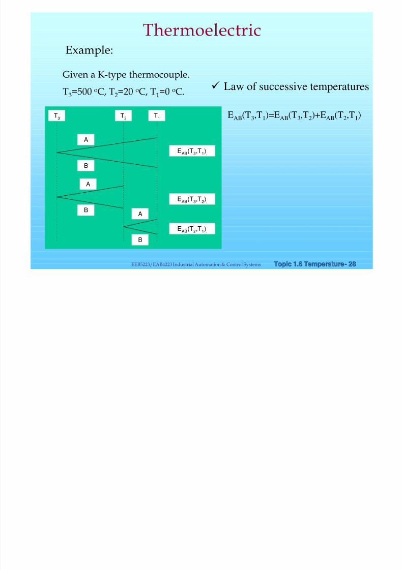
Example:
Given a K-type thermocouple.
T3=500 oC, T2=20 oC, T1=0 oC.
Thermoelectric
T3
T2
T1
A
B
A
B
B
A
EAB(T3,T1),
EAB(T2,T1),
EAB
(T3,T
2),
EAB(T3,T1)=EAB(T3,T2)+EAB(T2,T1)
ü Law of successive temperatures

8/8/2019 Chapter6 Temperature Measurement 08 v3
http://slidepdf.com/reader/full/chapter6-temperature-measurement-08-v3 29/36
Topic 1.6 TemperatureTopic 1.6 Temperature-- 2929EEB5223/EAB4223 Industrial Automation & Control Systems
EAB(T3,T1)=EAB(T3,T2)+EAB(T2,T1)
Reading from REFERENCE THERMOELECTROMOTIVE FORCETable
(IEC 584-1977, BS 4937-1973, JIS C 1602-1981, DINIEC 584-1984,ASTM E230-1983, ANSI MC96.1-1982)
EAB(T3,T1)=20 640 lV, EAB(T2,T1)=798 lV.
Accordingly, EAB(T3,T2) = EAB(T3,T1) - EAB(T2,T1) =19 842 lV.
Thermoelectric

8/8/2019 Chapter6 Temperature Measurement 08 v3
http://slidepdf.com/reader/full/chapter6-temperature-measurement-08-v3 30/36
Topic 1.6 TemperatureTopic 1.6 Temperature-- 3030EEB5223/EAB4223 Industrial Automation & Control Systems
ü Practical use requires the followingqualities:
i. Good corrosion resistance, robustness againstgases, etc.
ii. Large thermo-electromotive force.iii. Good heat resistance and ability to maintain
mechanical strength at high temperatures.
iv. Stable thermo-electromotive force even over longperiods of use, with small thermocouple loss.
v. Interchangeability: thermocouples of the sametype normally have the same characteristics.
Thermoelectric
8/8/2019 Chapter6 Temperature Measurement 08 v3
http://slidepdf.com/reader/full/chapter6-temperature-measurement-08-v3 31/36
Topic 1.6 TemperatureTopic 1.6 Temperature-- 3131EEB5223/EAB4223 Industrial Automation & Control Systems
ü Features of Base Metal Thermocouples:a. K-type (chromel-alumel)
-Can be used in an oxidizing environment
-Deteriorates slowly in a reducing environment
-Strong against metal vapors
-Good linearity of thermoelectromotive force
-Used for temperature 550oC to 1250oC.b. E-type (chromel-constantan)
-Good resistance to corrosion and oxidation
- Deteriorates slowly in a reducing environment
-Large thermoelectromotive force
-High electrical resistance
-Little measurement lag
-Used for temperature up to 850oC.
Thermoelectric

8/8/2019 Chapter6 Temperature Measurement 08 v3
http://slidepdf.com/reader/full/chapter6-temperature-measurement-08-v3 32/36
Topic 1.6 TemperatureTopic 1.6 Temperature-- 3232EEB5223/EAB4223 Industrial Automation & Control Systems
ü Features of Base Metal Thermocouples:
c. J-type (iron-constantan)-Can be used in reducing environments
-Rusts easily
-Good linearity, relatively large thermoelectromotive force,
but exhibit hysterisis thermoelectromotive force at hightemperature (800oC)
-Used for temperature up to 850oC.d. T-type (copper-constantan)
-Suited for use at low and extremely low temperatures
- Suited for use in reducing environments
-Large heat transfer error. -
-Used for temperature up to 400oC.
Thermoelectric

8/8/2019 Chapter6 Temperature Measurement 08 v3
http://slidepdf.com/reader/full/chapter6-temperature-measurement-08-v3 33/36
Topic 1.6 TemperatureTopic 1.6 Temperature-- 3333EEB5223/EAB4223 Industrial Automation & Control Systems
ü Features of Noble Metal Thermocouples:a. B-type (Platinum-30% rhodium), R-type (Platinum-13%
rhodium), S-type (Platinum-10% rhodium)
-Can be used continuously in an oxidizing environment, butnot suited for use in a reducing environment.
-Good resistance to corrosion and chemicals.
-Easily degenerated by hydrogen or metal vapors.
-Suited for measurement of high temperatures.
-Small thermo-electromotive force, especially the B-type.
e.g., Pt.40%Rh-Pt.20%Rh thermocouple can measure temperatures
near 1900oC., but has unusually low electromotive force.
Note: For noble metal thermocouple, the first mentioned material is the negative
polarity, and vice versa for base material.
Thermoelectric

8/8/2019 Chapter6 Temperature Measurement 08 v3
http://slidepdf.com/reader/full/chapter6-temperature-measurement-08-v3 34/36
Topic 1.6 TemperatureTopic 1.6 Temperature-- 3434EEB5223/EAB4223 Industrial Automation & Control Systems
The reference junction (RJ), or the cold junction, is usually at 0oC.
If it is not possible to maintain RJ at 0oC, a correction must be made tothe mV values shown in the thermocouple tables.
The following eqn. can be used when RJ deviates from 0oC.
mV = MJ –RJ ,
where MJ is the measuring junction temperature (or the hot junction)
Calculation steps:
a. From thermocouple table, obtain the mV (based on 0oC RJ)corresponding to the actual temperature of the thermocouple RJ.
b. Add algebraically the value in (a) to the mV read on the measuringinstrument.
c. Convert the mV obtained into terms of temperature directly from thesame table.
Thermoelectric
8/8/2019 Chapter6 Temperature Measurement 08 v3
http://slidepdf.com/reader/full/chapter6-temperature-measurement-08-v3 35/36
Topic 1.6 TemperatureTopic 1.6 Temperature-- 3535EEB5223/EAB4223 Industrial Automation & Control Systems
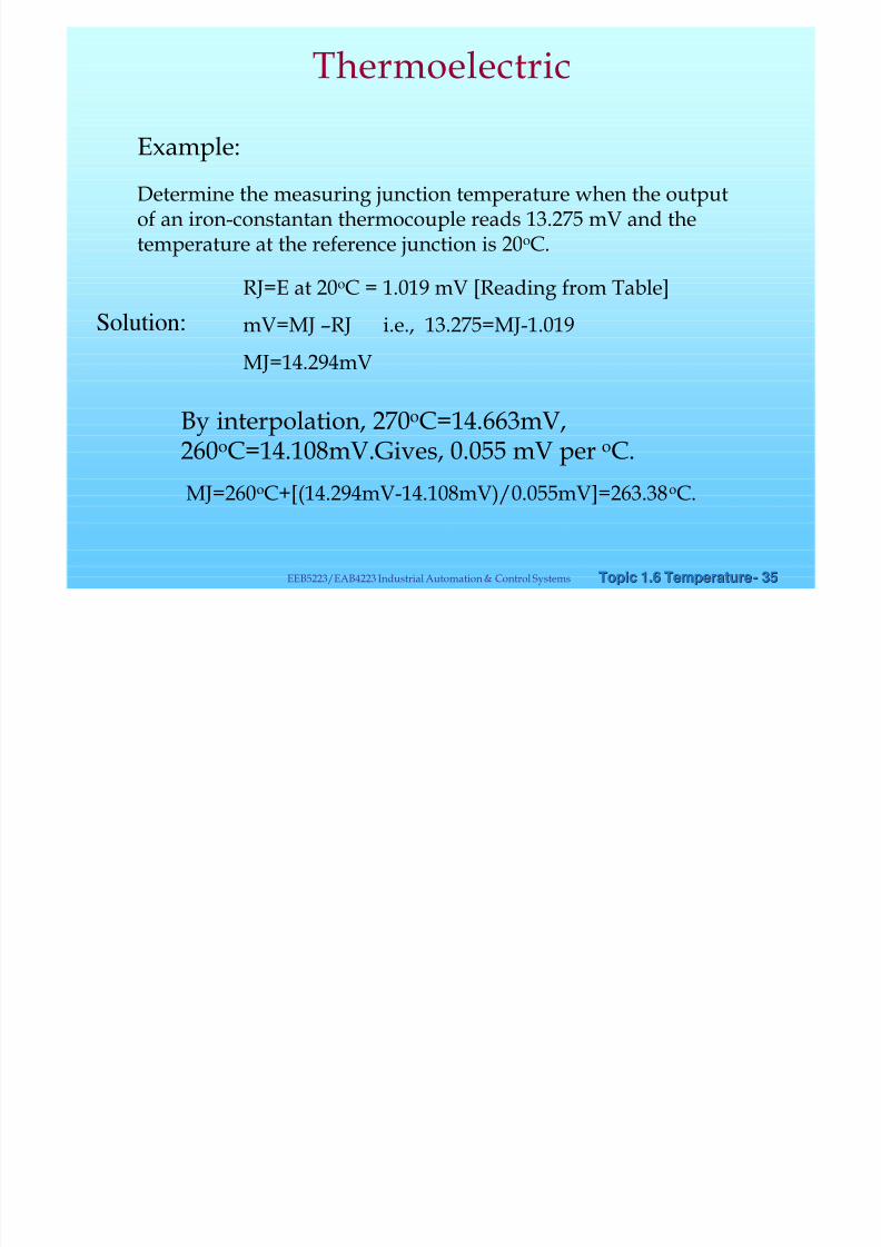
Example:Determine the measuring junction temperature when the outputof an iron-constantan thermocouple reads 13.275 mV and thetemperature at the reference junction is 20oC.
Solution:
RJ=E at 20oC = 1.019 mV [Reading from Table]
mV=MJ –RJ i.e., 13.275=MJ-1.019
MJ=14.294mV
By interpolation, 270oC=14.663mV,260oC=14.108mV.Gives, 0.055 mV per oC.
MJ=260oC+[(14.294mV-14.108mV)/0.055mV]=263.38oC.
Thermoelectric

8/8/2019 Chapter6 Temperature Measurement 08 v3
http://slidepdf.com/reader/full/chapter6-temperature-measurement-08-v3 36/36
Topic 1.6 TemperatureTopic 1.6 Temperature-- 3636EEB5223/EAB4223 Industrial Automation & Control Systems
Temperature
RorV
Thermistor –highlysensitive RTD- stable
Thermocouple-wide range
Comparisons of Temperature sensors
800o
C
End of Lecture notes on Temperature MeasurementEnd of Lecture notes on Temperature Measurement