chapter iii - suranaree university of technologyeng.sut.ac.th/me/box/1_54/425206/chapter iii.pdf ·...
TRANSCRIPT

Chapter IIIA review of the fundamental
formulation of stress, strain,
and deflection
Mechanics of Materials II

Outline• Introduction
• Assumtions and limitations
• Axial loading
• Torsion of circular shafts
• Beam in bending
• Bending of symmetric beams in two planes
• Thin-walled pressure vessels
• Superposition
• Statically indeterminate problems
• Stress and strain transformations*
• Buckling instability of columns

Introduction
• The basic topics from mechanics of materials I
include…
– Direct axial load
– Shear load
– Torsion in circular shafts
– Transverse loading of long, straight, narrow beam
• The purpose of this chapter is to provide a
concise review of the fundamental formulation
(stress, strain, and deflection)

Assumptions and limitations
• Homogeneous, Isotropic and linear strain-stress
relations
• Cross section are exact, and constant or gradually
varying in the normal direction.
• The point of load or support connection are at suffer
large distance for interested point
• The applied load/ or support connection are perfectly
positioned geometrically
• Load are static and applied very gradually
• No initial stress effect or residual stresses

Axial loading
• Axial stresses
(a) elongation of the prismatic bar
(b) freebody diagram
xP
A

Axial loading
xx
xy z
E
E
xx
xy z
P
AE
P
AE
• Axial strains and deflection
• Hooke‟s law 1D

Important equations
= d/L (Geometry of deformation)
= P/A (Equilibrium Condition)
= E (Material behavior)
d PL/AE (Deformation)
The product (AE) is called axial rigidity

Saint-Venant„s principle

STRESS CONCENTRATIONS
maxt
nom
K

STRESS CONCENTRATION CHARTS


Stepped bar with multiple loadings

Flexibility versus stiffness
Flexibility, f
Stiffness, k

Non-uniform bars

Example 3.2-1: The limitation of homogeneous materials

Example 3.2-2: Deformation due to weight of the rod

Example 3.2-3: the displacement of two cables

Example of a stepped bar
- Section plane at the change-
of-load point
- determine the internal force in
each section
- determine the deformation in
each section

Example: Displacement of a three-member device
Given: The rigid bar BC is supported by the 5/8 in
diameter (rod AB) and ½ in (rod CD) which under
load P = 12 kip at point E. Each of the rods is mad of
aluminum alloy6061 with E=10x106 psi
Find: The deflection at point E

Example: Displacement of a three-member device

Quiz: Axial loadingAs shown in Figure below, a rigid rod ABC is suspended by two
wires. The wire AD is made of steel have cross-sectional area
As = 0.14 in2 and elastic modulus Es = 30x106 psi. For the
aluminum-alloy wire CE, cross-section area and elastic
modulus Aa =0.28 in2 and Ea = 10x106 psi, respectively.
Determine the displacement of point B caused by the load
P = 6 kips

Torsion of circular shafts
• The plane cross sections perpendicular to the axis of the bar remain plane after the application of a torque: points in a given plane remain in that plane after twisting.
• Furthermore, expansion or contraction of a cross section does not occur, nor does a shortening or lengthening of the bar. Thus all normal strains are zero.
• The material is homogeneous and isotropic.
Assumptions

The maximum shear strain at the outer radius c is given by:
Shear strain at any arbitrary radius r is given by:

Torsion formula for circular shafts (C. A. Coulomb, in
about 1775

Important equationsIn SI units if T is in N-m, c is in meters and J is in
m4, then t is in Pa. In English units if T is in in-
lb/sec, c is in inch and J is in inch4, then t is in psi.
J is called the polar moment of inertia of the entire
cross section of a bar. For solid circular and hollow
cross sections, J is given by the formulas (on the
next slide):

Important formulas for “J“
Jsolid = 0.5pc4, where c is the radius of the bar
In terms of the bar diameter, J = 0.03125pd4
Jhollow = 0.5p(c4 – b4), where c and b are the
inner and outer radii of the bar
In terms of the diameters,
J = 0.03125p(do4 – di
4)

Important formulas for “J“
For thin-walled circular members (i.e., r/t ≥ 10),
an approximate formula for J is given by:
J = 2pr3t, where r is the mean radius and t is the
thickness of the tube, respectively.

Example3.31: A transmitted torque of step shaft

Example of an application
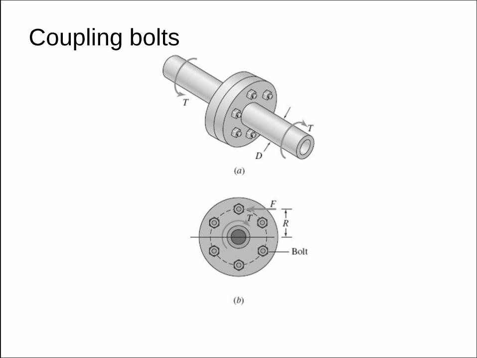
Coupling bolts

Angle of twist

Equation for angle of twist
Geometry of deformation:
gmax = cf/L
Equilibrium condition:
tmax = Tc/J
Material behavior:
gmax = tmax/G

Equation for angle of twist
Combining the previous equations yield:
f TL/GJ
Torsional spring stiffness:

Stepped bar with multiple loads

Torsion failures
(a) Brittle material
(b) Ductile material

Torsion tests

Design of circular shafts

In SI units:
In English units:

Case study

Beam in bending
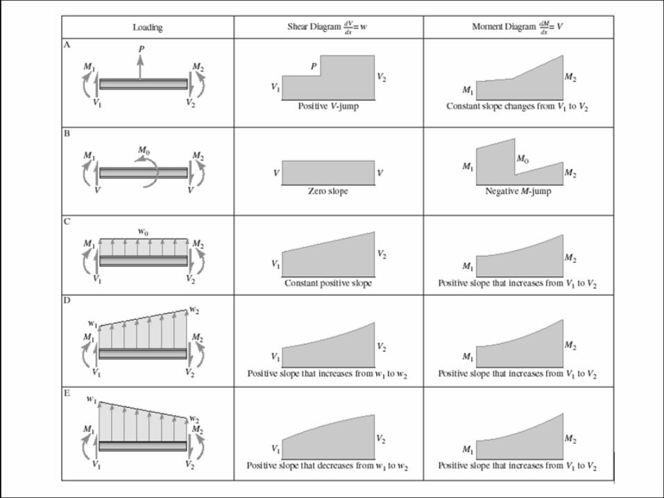
Shear Force (SF) & Bending Moment (BM)
Equations and Diagram
• Isolation internal transverse planar surface
• Singularity functions
Bending stresses
Transverse shear stresses
Bending strain and deflections
Bending of symmetric beams in two planes

Types of beams
Simple beam Cantilever beam
Overhang beam

Sign convention
In this text book..
For some other text book..

In this text book..

For some other text book..

Singularity functions
Forming a single equation for describe any
discontinuous functions..
( ) n
nF x x a
nWhere is any integer
( )0
( )( )
0
n
n
n
n
n
when x aF x x a
when x a
x a when x aF x x a
when x a
0For n
0For n


Example D.2-1: load-intensity equation
1 0 0 2 1 1( ) 0 0A C D Eq x R x w x w x a M x b P x c R x L
1 0 0 2 1 1( ) A C D Eq x R x w x w x a M x b P x c R x L

1
1
0
10
1
n
n
n
x a c for n
x a dxx a c for n
n
Integration rules
Example
2 1x a dx x a c
1 21
2x a dx x a c

Example 3.4-1: SFD and BMD of Overhang beam

Distribution of bending stress in a beam.
Normal stresses
In this formula, S is called the
section modulus (S = I/c)

Doubly symmetric cross-sectional shapes.

Example 3.4-2: Simply supported beam

Example:
Single- overhang
beam with
distributed load and
T-cross section

Two-plane bending problem for practice
Calculate the diameter of the shaft based on maximum bending stress

Stress concentration in bending


Transverse shear stresses
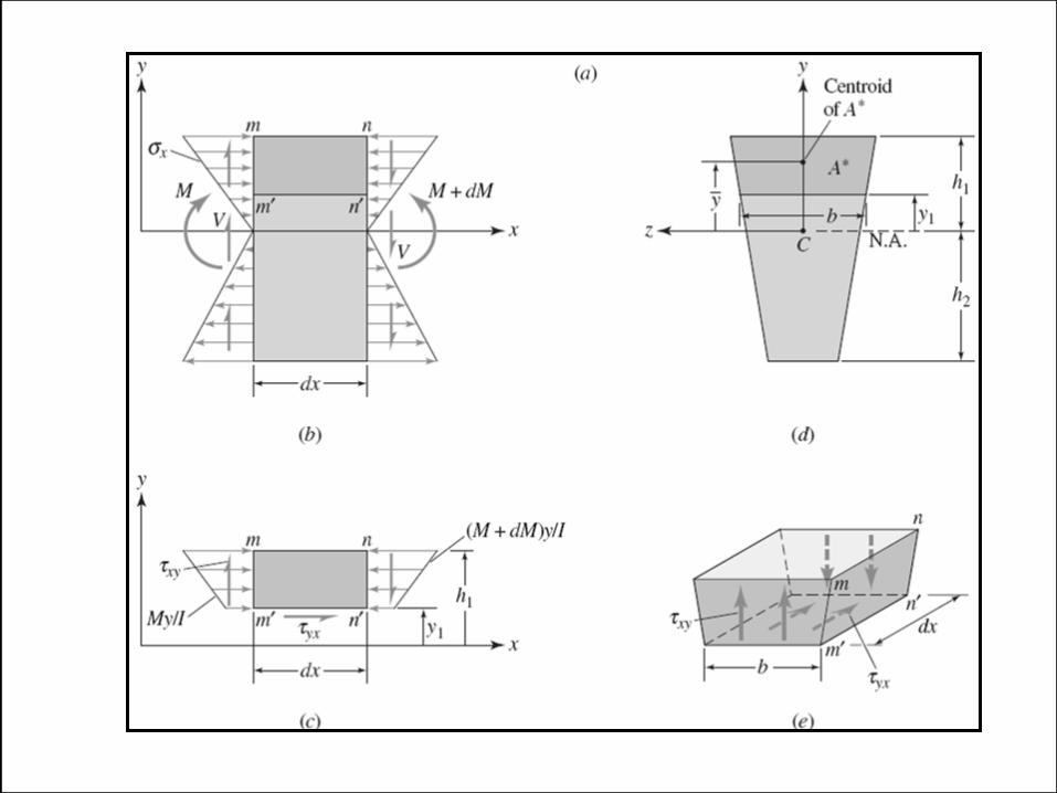

The shear formula
Q is the first moment of area given by

Shear Stress Distribution
in Rectangular Beams

Example 3.4-3: Shear stress distribution in solid
rectangular cross section beam

SOLID CIRCULAR SECTION BEAMS

HOLLOW CIRCULAR SECTION BEAMS

Comparison of Shear and Bending Stresses

If L = 10h (“long” beam), then this ratio is only
1/20, which means that tmax is only 5% of max

Bending strain and deflection
zx
z
M y
EI z
y z
z
M y
EI
2(1 ) y
xy
z
V Q
E I b
g

Bending strain and deflection
Positive loads and internal force resultants.
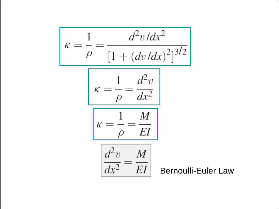
Bernoulli-Euler Law


Boundary conditions

Method of integration
Find:
(a) Determine the equation of the elastic curve using
the double-integration approach.
(b) Derive the equation of the elastic curve using the
multiple-integration approach.
(c) Obtain the maximum deflection and the slopes.

The bending moment is given by:
Double integration method:

Integrating twice in x gives:
Applying the boundary conditions we obtain:
C2 = 0 and C1 = - w L3/24

Slope and deflection are then given by:

Largest displacements and largest slopes:

Example 3.4-5: Simple supports with intermediate load
Find: Deflection as function of
x of the centroidal axis
- Discontinuous equations
- singularity functions

Bending of symmetric beam in two planes
y zx
t z
M z M y
I I
zx
z
M y
I
2 2
z y zM M M
z y zI I I
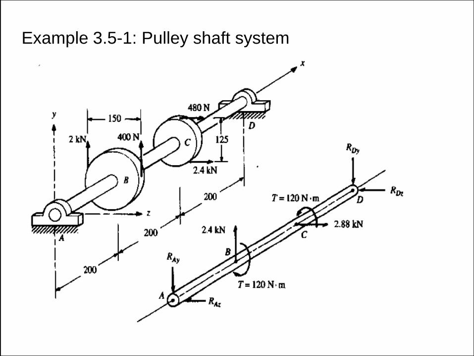
Example 3.5-1: Pulley shaft system

Thin-walled pressure vessels
If the ratio of the wall thickness (t) to the inner
radius (r) is equal or less than about 1/10 (or r/t ≥
10), the vessel is classified as thin-walled
In fact, in thin-walled vessels, there is often no distinction made between the inside and outside radii
because they are nearly equal.

Membrane equation
p
r r t
f
f
2 20: 2 sin 2 sin 0nF tr tr p r r f f f
f f f

Cylindrical pressure vessel
Tangential stress:
Axial (longitudinal) stress:
z

Spherical pressure vessels
Tangential stress due to internal pressure:
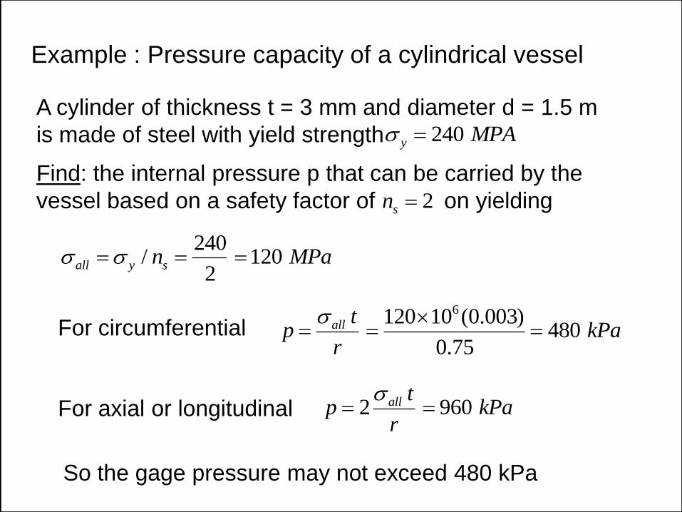
Example : Pressure capacity of a cylindrical vessel
A cylinder of thickness t = 3 mm and diameter d = 1.5 m
is made of steel with yield strength
Find: the internal pressure p that can be carried by the
vessel based on a safety factor of on yielding
240y MPA
2sn
240/ 120
2all y sn MPa
For circumferential 6120 10 (0.003)
4800.75
all tp kPa
r
For axial or longitudinal 2 960all tp kPa
r
So the gage pressure may not exceed 480 kPa

Superposition
Works well for beams with small deflections that follow
linear Hooke’s law
For the special case when a = b = L/2:

Example: Slope and Deflection of a beam with an overhang
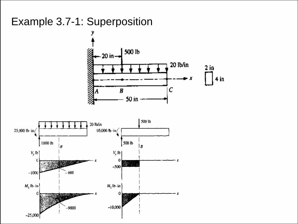
Example 3.7-1: Superposition

Example 3.7-2: Deflection equation (overhang beam)

Example 3.7-3: State of stress (Transverse load+Torque)

Statically Indeterminate Problems
• Step 1 : Solve for all possible unknown reactions
• Step 2 : Subtract the number for remaining Eqn
from the number of remaining unknown
Ex. (n = 3 - 2) = 1
• Step 3 : Eliminate n of unknown reactions
(redundant unknown)
• Step 4 : Considering redundant unknown as “applied
force”- the deflection and/or rotation at the n
point
• Step 5 : Using the method of superposition
• Step 6 : Solve the simultaneous Eqn
• Step 7 : Substitute the results of the Step 6 into Step 1

Example 3.8-2: Deflection equation (overhang beam)


