chapter 9 details plan - oregon.gov · that is located on the pole itself is measured by ......
TRANSCRIPT

2017 Traffic Signal Design Manual
Oregon Department of Transportation 9-i June 2017 Traffic Standards and Asset Management Unit Chapter 9 – Details Plan
Chapter 9 DETAILS PLAN
Contents
9 DETAILS PLAN ................................................................................................................................ 9-1 9.1 General .......................................................................................................................................... 9-1 9.2 Pole Entrance Chart - General ...................................................................................................... 9-1
9.2.1 When is a pole entrance chart needed? ........................................................................................... 9-1 9.3 Pole Entrance Chart – Mast Arm .................................................................................................. 9-2
9.3.1 First 3 Columns ................................................................................................................................. 9-2 9.3.2 Equipment on the Pole ..................................................................................................................... 9-2 9.3.3 Equipment on the Mast Arm ............................................................................................................ 9-9 9.3.4 Foundation Information ................................................................................................................. 9-10 9.3.5 Luminaires ...................................................................................................................................... 9-11 9.3.6 Orientation Diagrams ..................................................................................................................... 9-12 9.3.7 Detailing Dual Mast Arm Pole in the Pole Entrance Chart .............................................................. 9-13
9.4 Pole Entrance Chart – Strain Pole ............................................................................................... 9-17 9.4.1 First 4 Columns ............................................................................................................................... 9-17 9.4.2 Messenger Cable Attachment Height (MAH) ................................................................................. 9-18 9.4.3 Equipment on Pole ......................................................................................................................... 9-21 9.4.4 Equipment on Span Wire ................................................................................................................ 9-23 9.4.5 Foundation Information ................................................................................................................. 9-23 9.4.6 Luminaires ...................................................................................................................................... 9-23 9.4.7 Orientation Diagrams ..................................................................................................................... 9-24
9.5 Custom Details Created From Standard Details ......................................................................... 9-24 9.5.1 ITS Equipment ................................................................................................................................. 9-24

2017 Traffic Signal Design Manual
Oregon Department of Transportation 9-1 June 2017 Traffic Standards and Asset Management Unit Chapter 9 – Details Plan
9 DETAILS PLAN
9.1 General The details plan sheet is used to show ANY design information that cannot be shown on the standard designated plan sheet. This is typically due to a drafting space issue; for example, the pole entrance chart is contained on a separate details plan sheet because there is not enough room on the signal plan sheet to show all the pertinent signal design information. Other common design information shown on detail sheets includes customized diagrams created from Standard Details. This chapter will cover the two basic types of information routinely contained on the details plan sheet; the pole entrance chart and custom details created from standard details.
9.2 Pole Entrance Chart - General The pole entrance chart lists the micro details related to the signal pole and all mounted signal equipment. Some of the information listed in the pole entrance chart is redundant (e.g. the mast arm length is listed on the signal plans AND in the pole entrance chart), but this chart aids in reviewing signal pole submittals and also serves as a quick glance summary for how many and what type of poles are needed for the project. There are two default types of pole entrance charts; one for mast arms (See Section 9.3) and one for span wires (See Section 9.4).
9.2.1 When is a pole entrance chart needed? A pole entrance chart is required for any work that involves installing a new push button post, pedestrian/vehicle pedestal, or signal pole.
A pole entrance chart is recommended for any work that modifies the equipment located on an existing mast arm, span wire, or signal pole. The exception to this recommendation is for minor modifications where all the necessary information (contained in the pole entrance chart) can be very clearly shown on the signal plan sheet.
If the project involves a combination of mast arms and span wires, both charts will need to be included.

2017 Traffic Signal Design Manual
Oregon Department of Transportation 9-2 June 2017 Traffic Standards and Asset Management Unit Chapter 9 – Details Plan
9.3 Pole Entrance Chart – Mast Arm The following section discusses how to fill out the mast arm pole entrance chart properly. If any of the columns do not apply to the pole that is being detailed, leave those columns blank.
9.3.1 First 3 Columns The first 3 columns list the basic pole identifiers: the unique pole number, the signal plan sheet the pole is located on, and the type of pole it is (signal pole type as per standard drawing TM650, pedestrian pedestal, vehicle pedestal or pedestrian push button post). See Figure 9-1. Figure 9-1 | Basic Pole Information
9.3.2 Equipment on the Pole The next five columns detail all the equipment that is located on the pole itself. All equipment that is located on the pole itself is measured by degrees to ensure the correct orientation of the equipment. The degrees are measured to the nearest 5 degree increment. The pedestrian signal degrees column shows the location of the clamshell mount for the pedestrian signal (which is 90 degrees from the face of the signal indication). If more than one pedestrian signal indication is mounted to a pole an “&” symbol is used between the two locations. See Figure 9-2.
Figure 9-2 | Pedestrian Signal Degrees
2017 Traffic Signal Design Manual
Oregon Department of Transportation 9-3 June 2017 Traffic Standards and Asset Management Unit Chapter 9 – Details Plan
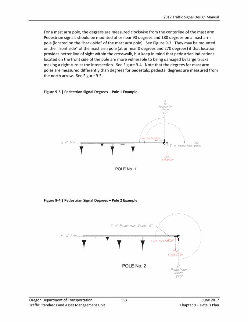
For a mast arm pole, the degrees are measured clockwise from the centerline of the mast arm. Pedestrian signals should be mounted at or near 90 degrees and 180 degrees on a mast arm pole (located on the “back-side” of the mast arm pole). See Figure 9-3. They may be mounted on the “front side” of the mast arm pole (at or near 0 degrees and 270 degrees) if that location provides better line of sight within the crosswalk, but keep in mind that pedestrian indications located on the front side of the pole are more vulnerable to being damaged by large trucks making a right turn at the intersection. See Figure 9-4. Note that the degrees for mast arm poles are measured differently than degrees for pedestals; pedestal degrees are measured from the north arrow. See Figure 9-5. Figure 9-3 | Pedestrian Signal Degrees – Pole 1 Example
Figure 9-4 | Pedestrian Signal Degrees – Pole 2 Example

2017 Traffic Signal Design Manual
Oregon Department of Transportation 9-4 June 2017 Traffic Standards and Asset Management Unit Chapter 9 – Details Plan
Figure 9-5 | Pedestrian Signal Degrees – Pole 3 Example
The origin for measuring degrees is NOT the same for mast arm poles (clockwise from arm) and pedestals (clockwise from the north arrow).
When two pedestrian indications are mounted to the same pole, the acute angle between the two pedestrian heads should be 90 degrees or greater on a large diameter pole (mast arm and strain poles) and shall be 90 degrees or greater on a small diameter pole (pedestals). See Figure 9-6. When the indications are placed closer than 90 degrees several things may occur:
• The indications can be occluded • The clamshell mounting brackets cannot be installed (the hardware for each indication
would overlap) • It may be difficult to fully open the clamshell and/or the pedestrian indication for
maintenance Figure 9-6 | Pedestrian Signal Degrees – Angle Between Two Pedestrian Indications

2017 Traffic Signal Design Manual
Oregon Department of Transportation 9-5 June 2017 Traffic Standards and Asset Management Unit Chapter 9 – Details Plan
The terminal cabinet degrees shows the location of the factory welded hub required to mount the terminal cabinet to the signal pole (see TM450 and TM488 for additional details). See Figure 9-7. Pedestals do NOT have a terminal cabinet. For mast arm poles, the terminal cabinet degrees should be located at 180 degrees unless there is some obstruction which would make accessing the terminal cabinet difficult at 180 degrees. See Figure 9-8. The Region Electrical Crew will provide direction on the best location to mount the terminal cabinet in these situations.
Figure 9-7 | Terminal Cabinet Degrees
Figure 9-8 | Terminal Cabinet Degrees: Access Obstruction
Terminal Cabinet Located at 180 degrees difficult to access due to fence.

2017 Traffic Signal Design Manual
Oregon Department of Transportation 9-6 June 2017 Traffic Standards and Asset Management Unit Chapter 9 – Details Plan
The sign degree column shows the location of the face of the sign mounted on the signal pole, typically a guide sign. See Figure 9-9. The other details for the guide sign fabrication and mounting will be shown on the signing plans and will be paid for as a sign bid item (not under the lump sum traffic signal bid item). Guide signs mounted to signal poles must meet the requirements shown in standard drawings TM650 and TM680 (such as a maximum area of 60 square feet, maximum height of 7 feet and maximum width of 12 feet). If at all possible, the guide sign should be designed to fit within these parameters. If the sign cannot be meet these requirements and cannot be mounted in a different location, then a standard signal pole cannot be used and a custom designed pole must be used. If a sign other than a guide sign is mounted to the pole (i.e. a NO TURN ON RED sign), this column can be used to detail the orientation. In the case where multiple signs are mounted to the same pole (i.e. guide sign AND a regulatory) it is recommended to add a column to the “equipment on pole” to distinguish between the two signs. See Figure 9-13. Multiple signs on the same pole must be evaluated to ensure that a standard pole will accommodate the loading as per TM660 and TM680.
Figure 9-9 | Sign Degrees (typically for a guide sign)

2017 Traffic Signal Design Manual
Oregon Department of Transportation 9-7 June 2017 Traffic Standards and Asset Management Unit Chapter 9 – Details Plan
The traffic signal degree column shows the location of the face of the vehicular signal indication mounted on the pole. See Figure 9-10. Vehicular signal indications are not typically mounted to signal poles unless there is need for a near-side signal indication or the intersection geometry/phasing requires unique placement of the signal indication. Figure 9-10 | Traffic Signal Degrees
The origin for measuring the degrees is NOT the same for mast arm poles and pedestals.

2017 Traffic Signal Design Manual
Oregon Department of Transportation 9-8 June 2017 Traffic Standards and Asset Management Unit Chapter 9 – Details Plan
The photo-electric cell column shows the location of the mount used for the photo electric cell. See Figure 9-11. The photo-electric cell’s sensor must be oriented to the north to operate most effectively, so when mounting the photo electric cell to the pole, ensure that photo cell’s sensor will NOT be pointed directly at the signal pole. See Figure 9-12.
Figure 9-11 | Photo Electric Cell
Figure 9-12 | Photo Electric Cell Orientation

2017 Traffic Signal Design Manual
Oregon Department of Transportation 9-9 June 2017 Traffic Standards and Asset Management Unit Chapter 9 – Details Plan
There may be cases where additional columns may need to be added to the “equipment on pole” section. Typical examples include a column for the “crosswalk closed” sign if it needs to be mounted to the signal pole or a “Cam. Deg.” column if a video detector/ITS camera is mounted to the pole. See Figure 9-13. A column is NOT needed for pushbuttons as these are installed as per standard drawing TM467 and can only be installed in one orientation. Figure 9-13 | Adding Columns
9.3.3 Equipment on the Mast Arm The next columns show all the equipment located on the mast arm. See Figure 9-14. The first column shows the mast arm length. The following columns list each piece of equipment that is located on the mast arm, starting from the tip of the mast arm and going towards the signal pole. For each piece of equipment, the distance in feet from the tip of the mast arm (numerator) AND a description of the type of equipment (denominator) is included. The description is a standard abbreviation that is defined in a legend. The distance is shown in decimal format, with measurements rounded to the nearest half foot. Figure 9-14 | Mast Arm Equipment

2017 Traffic Signal Design Manual
Oregon Department of Transportation 9-10 June 2017 Traffic Standards and Asset Management Unit Chapter 9 – Details Plan
9.3.4 Foundation Information The foundation information columns show the foundation number and the foundation depth for each signal pole. See Figure 9-15. The foundation number is specific to the type of mast arm/strain pole type used and is found on standard drawing TM653 in the “standard foundations” chart. The foundation depth is determined using site specific information documented in a geotechnical report according to the ODOT Traffic Structures Design Manual. This report is produced by the Geotechnical Engineer once the location of the signal poles has been determined. The foundation depth is shown in decimal format to the tenth of a foot. The geotech report is also referenced on the plan sheet just below the pole entrance chart with the name of the agency/firm that produced the report and the date of the report. Do NOT include any foundation information for pedestrian pedestals, vehicle pedestals or pedestrian push button posts as these standard foundations do not have any variables and are installed according standard drawing TM457. Leave these columns blank.
Figure 9-15 | Foundation Information

2017 Traffic Signal Design Manual
Oregon Department of Transportation 9-11 June 2017 Traffic Standards and Asset Management Unit Chapter 9 – Details Plan
9.3.5 Luminaires The illumination columns show the details for the luminaires mounted on signal poles. See Figure 9-16. The information comes from the illumination analysis. The following are typical values for illumination:
15 foot arm length
0 arm degrees (i.e. “in-line” with the mast arm)
35 to 40 foot mounting height
Standard luminaire type is LED
Standard fixture type for LED is Type 3.
Standard wattage is from 130 to 275, depending on design.
Figure 9-16 | Luminaire Information

2017 Traffic Signal Design Manual
Oregon Department of Transportation 9-12 June 2017 Traffic Standards and Asset Management Unit Chapter 9 – Details Plan
9.3.6 Orientation Diagrams The orientation diagrams provide a legend for how to read the information provided by the pole entrance chart. There are two standard orientation diagrams that are included with the pole entrance chart:
The mast arm orientation diagram. See Figure 9-17. The pedestrian pedestal/vehicle pedestal orientation diagram (included only if this
type of pole is used on the project). See Figure 9-18.
Figure 9-17 | Mast Arm Orientation Diagram
Figure 9-18 | Pedestrian Pedestal/Vehicle Pedestal Orientation Diagram

2017 Traffic Signal Design Manual
Oregon Department of Transportation 9-13 June 2017 Traffic Standards and Asset Management Unit Chapter 9 – Details Plan
9.3.7 Detailing Dual Mast Arm Pole in the Pole Entrance Chart A dual mast arm pole is a custom designed pole and requires a few more pieces of information in the mast arm pole entrance chart (and signal plan sheet) than a standard mast arm pole. In addition, there is a specific pole orientation diagram that must be used for dual mast arm poles.
A dual mast arm pole has one mast arm labeled “A” and one labeled “B” as per the orientation diagram. This clearly designates which arm is being detailed in chart. See Figure 9-19. If possible (e.g. there is only one dual mast arm on the project or each dual mast is oriented in the same way), rotate the dual mast arm in the orientation diagram to match the orientation in the signal plan sheet. See Figure 9-20.
Figure 9-19 | Twin Mast Arm Pole Orientation Diagram

2017 Traffic Signal Design Manual
Oregon Department of Transportation 9-14 June 2017 Traffic Standards and Asset Management Unit Chapter 9 – Details Plan
Figure 9-20 | Twin Mast Arm Pole Orientation Diagram – Rotated
The information presented in section 9.3.7 applies to dual mast arm poles, with the Figure 9-21 through Figure 9-25 showing the slight modifications necessary to properly detail a mast arm pole in the pole entrance chart.
Figure 9-21 | Twin Mast Arm Pole – Pole Entrance Chart

2017 Traffic Signal Design Manual
Oregon Department of Transportation 9-15 June 2017 Traffic Standards and Asset Management Unit Chapter 9 – Details Plan
Figure 9-22 | Twin Mast Arm Pole – Equipment on Pole
Figure 9-23 | Twin Mast Arm Pole – Equipment on Mast Arm

2017 Traffic Signal Design Manual
Oregon Department of Transportation 9-16 June 2017 Traffic Standards and Asset Management Unit Chapter 9 – Details Plan
Figure 9-24 | Twin Mast Arm Pole – Foundation Information
Figure 9-25 | Twin Mast Arm Pole – Luminaires

2017 Traffic Signal Design Manual
Oregon Department of Transportation 9-17 June 2017 Traffic Standards and Asset Management Unit Chapter 9 – Details Plan
9.4 Pole Entrance Chart – Strain Pole The following section discusses how to fill out the strain pole entrance chart properly. If any of the columns do not apply to the pole that is being detailed, leave those columns blank.
9.4.1 First 4 Columns The first 4 columns list the basic pole and span identifiers: the signal plan sheet the pole is located on, the type of pole it is (signal pole type as per standard drawing TM661, the unique pole number (designated as the “FROM” pole), and the span (defined by the “TO” pole). See Figure 9-26. The type of strain pole is determined by the structural engineer performing the structural analysis based on the following information provided by the signal designer: pole location & span length, equipment & location of equipment on each span, and the Messenger Cable Attachment Height (MAH) for each pole. Figure 9-26 | Basic Pole and Span Information

2017 Traffic Signal Design Manual
Oregon Department of Transportation 9-18 June 2017 Traffic Standards and Asset Management Unit Chapter 9 – Details Plan
9.4.2 Messenger Cable Attachment Height (MAH) The next 2 columns after basic pole information show the messenger cable attachment height (MAH) for each messenger cable attached to the pole. All values should be reported in increments of 0.5 feet. For poles with 2 messenger cables attached, the MAH values must be separated by 0.5’ as per standard drawing TM661 and TM452. See Figure 9-27.
Figure 9-27 | Messenger Cable Attachment Height (MAH)
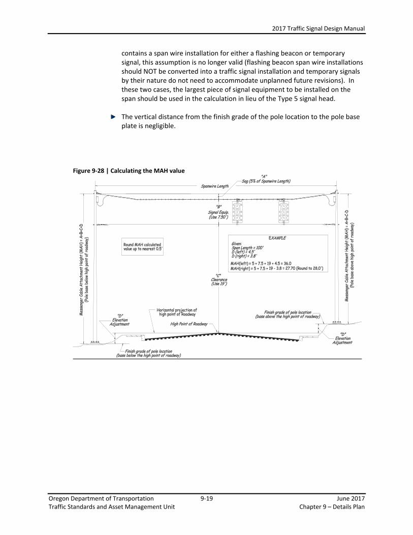
The MAH is defined as the distance from the baseplate of the signal pole (or ground line for temporary wood pole) to the point of attachment of the messenger cable. To determine the MAH, request a cross-section from the roadway designer for each span. To calculate the MAH, see Figure 9-28 which assumes the following:
The MAH values for the span are at approximately equal elevations (typically
within 1 foot of each other). If the elevations of the MAH for the span are different by more than 1 foot due to a super elevation or steep vertical grade, see Figure 9-29 for how to calculate the MAH.
19’ Maximum roadway clearance. The tolerance for the roadway clearance is 18’ minimum to 19’ maximum as per standard drawing TM450. Using the 19’ maximum value for calculating the MAH results in a conservative MAH value (from the perspective of roadway clearance).
A type 5 signal head is mounted at the lowest spot on the span which coincides with the highest spot on the roadway. This is a requirement of standard drawing TM660 which states that the strain pole supports, “Accommodate enough vertical space for a type 5 signal.” The results in a conservative MAH value and allows for future revisions to the traffic signal. However, if the project
2017 Traffic Signal Design Manual
Oregon Department of Transportation 9-19 June 2017 Traffic Standards and Asset Management Unit Chapter 9 – Details Plan
contains a span wire installation for either a flashing beacon or temporary signal, this assumption is no longer valid (flashing beacon span wire installations should NOT be converted into a traffic signal installation and temporary signals by their nature do not need to accommodate unplanned future revisions). In these two cases, the largest piece of signal equipment to be installed on the span should be used in the calculation in lieu of the Type 5 signal head.
The vertical distance from the finish grade of the pole location to the pole base plate is negligible.
Figure 9-28 | Calculating the MAH value

2017 Traffic Signal Design Manual
Oregon Department of Transportation 9-20 June 2017 Traffic Standards and Asset Management Unit Chapter 9 – Details Plan
There are rare cases where the roadway cross-section will result in unequal MAH elevations for the span (e.g. when there is a steep grade or super elevation). In these cases both the high point of the roadway AND the low point of the roadway is used to determine the MAH for each pole as per Figure 9-29. Using the method shown in Figure 9-29 is oversimplified and results in a conservative estimate for roadway clearance, as the low point in the catenary span will not actually occur at the locations shown when the MAH elevations are not equal.
Figure 9-29 | Calculating the MAH value – spans with MAH elevations differing by more than a foot

2017 Traffic Signal Design Manual
Oregon Department of Transportation 9-21 June 2017 Traffic Standards and Asset Management Unit Chapter 9 – Details Plan
9.4.3 Equipment on Pole The next five columns detail all the equipment that is located on the pole itself. All equipment that is located on the pole itself is measured by degrees to ensure the correct orientation of the equipment. The degrees are measured to the nearest 5 degree increment. The pedestrian signal degrees column shows the location of the clamshell mount for the pedestrian signal (which is 90 degrees from the face of the signal indication). If more than one pedestrian signal indication is mounted to a pole an “&” symbol is used between the two locations. The degrees for a strain pole are measured clockwise from the north arrow. The preferred mounting on the “back side” of the strain pole is shown in Figure 9-30. Figure 9-30 | Pedestrian Signal Equipment

2017 Traffic Signal Design Manual
Oregon Department of Transportation 9-22 June 2017 Traffic Standards and Asset Management Unit Chapter 9 – Details Plan
The terminal cabinet degrees shows the location of the factory welded hub required to mount the terminal cabinet to the signal pole (See TM452 & TM488 for additional details). For strain poles, the terminal cabinet should be located on the bisected interior angle formed by the two span wires for ease of maintenance. See Figure 9-31. Figure 9-31 | Terminal Cabinet on Strain Pole
The last 3 columns in the Equipment on Pole (sign deg., traffic signal deg., and photo electric cell) are detailed the same as for a mast arm pole, with the only exception being the origin of degree measurement (strain poles always measure degrees based off of the north arrow). See Section 9.3.2.

2017 Traffic Signal Design Manual
Oregon Department of Transportation 9-23 June 2017 Traffic Standards and Asset Management Unit Chapter 9 – Details Plan
9.4.4 Equipment on Span Wire The equipment on located on the span wire is detailed the same as the equipment located on the mast arm (see Section 9.3.3) with the two following exceptions (see Figure 9-32):
• The origin of measurement is based on the “From” pole • The “To” pole is listed as the last piece of equipment to define the length of the span
Figure 9-32 | Equipment on Span Wire
9.4.5 Foundation Information The same information presented for mast arm pole orientation diagram applies to strain poles (See Section 9.3.4).
9.4.6 Luminaires The same information presented in the mast arm pole orientation diagram applies to strain poles (See Section 9.3.5).
2017 Traffic Signal Design Manual
Oregon Department of Transportation 9-24 June 2017 Traffic Standards and Asset Management Unit Chapter 9 – Details Plan
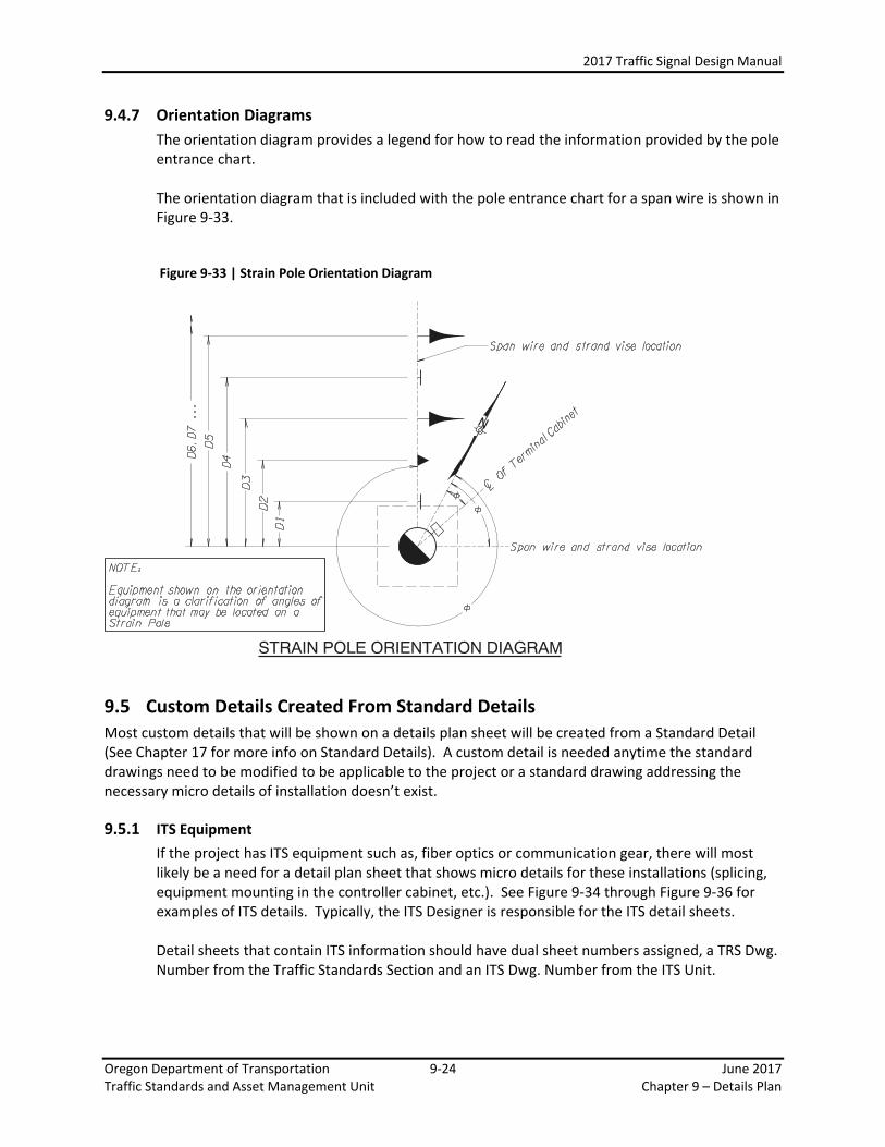
9.4.7 Orientation Diagrams The orientation diagram provides a legend for how to read the information provided by the pole entrance chart. The orientation diagram that is included with the pole entrance chart for a span wire is shown in Figure 9-33.
Figure 9-33 | Strain Pole Orientation Diagram
9.5 Custom Details Created From Standard Details Most custom details that will be shown on a details plan sheet will be created from a Standard Detail (See Chapter 17 for more info on Standard Details). A custom detail is needed anytime the standard drawings need to be modified to be applicable to the project or a standard drawing addressing the necessary micro details of installation doesn’t exist.
9.5.1 ITS Equipment If the project has ITS equipment such as, fiber optics or communication gear, there will most likely be a need for a detail plan sheet that shows micro details for these installations (splicing, equipment mounting in the controller cabinet, etc.). See Figure 9-34 through Figure 9-36 for examples of ITS details. Typically, the ITS Designer is responsible for the ITS detail sheets.
Detail sheets that contain ITS information should have dual sheet numbers assigned, a TRS Dwg. Number from the Traffic Standards Section and an ITS Dwg. Number from the ITS Unit.

2017 Traffic Signal Design Manual
Oregon Department of Transportation 9-25 June 2017 Traffic Standards and Asset Management Unit Chapter 9 – Details Plan
Figure 9-34 | ITS Fiber Splice Detail Example
Figure 9-35 | Communication Rack Detail Example

2017 Traffic Signal Design Manual
Oregon Department of Transportation 9-26 June 2017 Traffic Standards and Asset Management Unit Chapter 9 – Details Plan
Figure 9-36 | Din Rail Bracket Detail Example