chapter 8: thermal process (continued). diffusion process the process of materials move from high...
TRANSCRIPT

CHAPTER 8: THERMAL PROCESS (continued)

Diffusion Process• The process of materials move from high concentration regions to
low concentration regions, driven by thermal motion of molecules.
• The purpose is to drive in dopant into certain depth in semiconductor substrate after ion implantation process or spin on dopant technique.
• Most common physics phenomena• Materials disperse from higher concentration to lower concentration
region• Silicon dioxide as diffusion mask• Was widely used for semiconductor doping• “Diffusion Furnace” and “Diffusion Bay”

Diffusion Doping Process
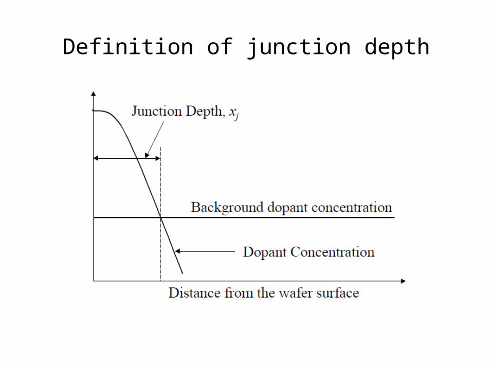
Definition of junction depth

Patterned diffusion doping process

Thermal Budget
• Dopant atoms diffuse fast at high temperature,
D = D0 exp (–Ea/kT)• Smaller device geometry, less room for dopant
thermal diffusion, less thermal budget• Thermal budget determines the time and
temperature of the post-implantation thermal processes

Thermal Budget Process

Thermal budget for device with different feature sizes

Diffusion Doping Process
• Both dopant concentration and junction depth are related to temperature.
• No way to independently to control both factor• Isotropic dopant profile• Replaced by ion implantation after the mid-1970s• Silicon dioxide as hard mask• Deposit dopant oxide• Cap oxidation– prevent dopant diffusion into gas phase• Drive-in
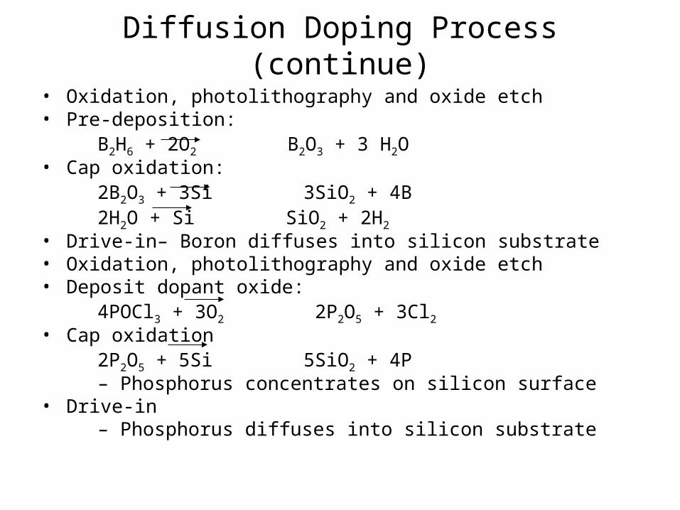
Diffusion Doping Process (continue)
• Oxidation, photolithography and oxide etch• Pre-deposition: B2H6 + 2O2 B2O3 + 3 H2O• Cap oxidation: 2B2O3 + 3Si 3SiO2 + 4B 2H2O + Si SiO2 + 2H2
• Drive-in– Boron diffuses into silicon substrate• Oxidation, photolithography and oxide etch• Deposit dopant oxide: 4POCl3 + 3O2 2P2O5 + 3Cl2• Cap oxidation 2P2O5 + 5Si 5SiO2 + 4P – Phosphorus concentrates on silicon surface• Drive-in – Phosphorus diffuses into silicon substrate

Phosphorus Diffusion System

Diffusion doping process sequence
Dopant Junction
Dopant
Deposited dopant oxide
Oxidation
Dopant drive-in

Limitation of Diffusion• Diffusion is isotropic process and always dope
underneath masking oxide• Can’t independently control junction depth and dopant
concentration
Application of Diffusion• Used for well implantation drive-in• R&D for ultra shallow junction (USJ) formation• Wells have the deepest junction depth• Need very high ion implantation energy• Cost of MeV ion implanters is very high• Diffusion can help to drive dopant to the desired junction
depth while annealing
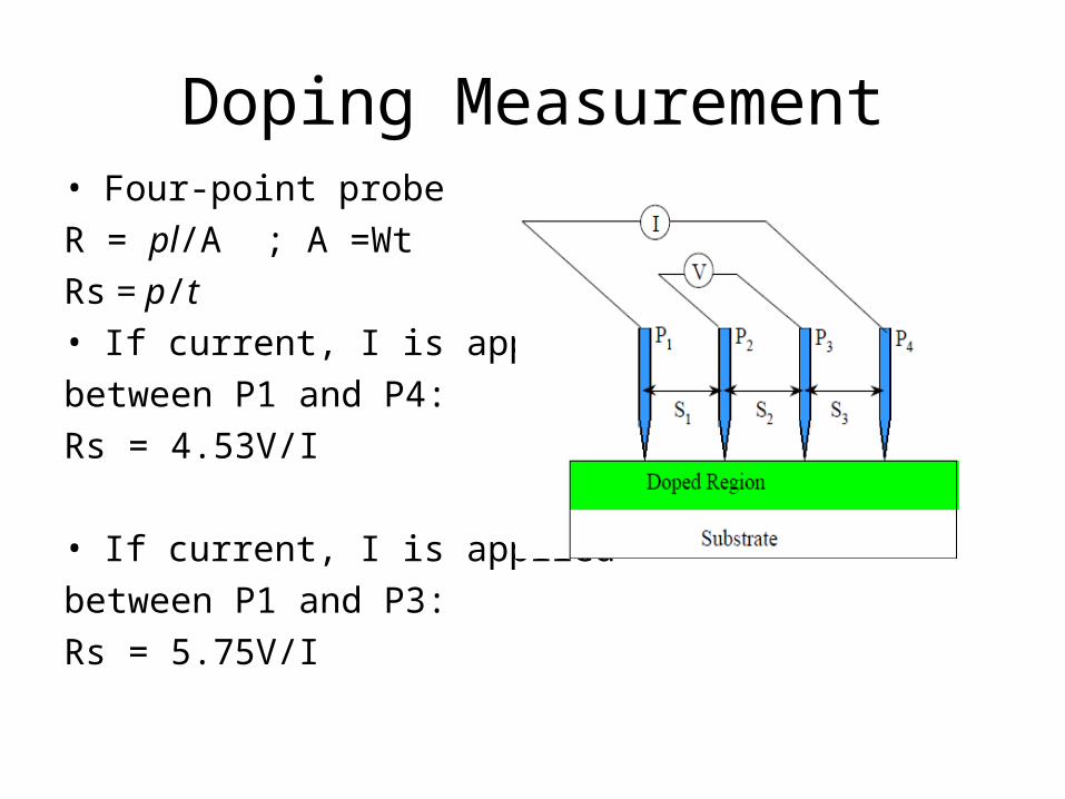
Doping Measurement• Four-point probe
R = pl/A ; A =Wt
Rs = p/t
• If current, I is applied
between P1 and P4:
Rs = 4.53V/I
• If current, I is applied
between P1 and P3:
Rs = 5.75V/I
Annealing
• The heating process in which a wafer is heated to achieve physical or chemical change with minimum material being added to or removed from the wafer surface.
Post-implantation Annealing
• Energetic ions damage crystal structure• Amorphous silicon has high resistivity• Need external energy such as heat for atoms to recover single
crystal structure• Only in single crystal structure dopants can be activated

Post-implantation Annealing (continue)
• Single crystal structure has lowest potential energy• Atoms tend to stop on lattice grid• Heat can provide energy to atoms for fast thermal motion• Atoms will find and settle at the lattice grid where has the
lowest potential energy position• Higher temperature, faster annealing

Before Ion Implantation
After Ion Implantation

Thermal Annealing

Alloy Annealing
• A thermal process in which different atoms chemically bond with each other to form a metal alloy.
• Widely used in silicide formation• Self aligned silicide (salicide)
– Titanium silicide, TiSi2
– Cobalt silicide, CoSi2• Furnace and RTP

Silicide
• Much lower resistivity than polysilicon• Used as gate and local interconnection• Used as capacitor electrodes• Improving device speed and reduce heat• generation• TiSi2, WSi2 are the most commonly used silicide• CoSi2, MoSi2, and etc are also used

Titanium Silicide Process
• Argon sputtering clean• Titanium PVD• RTP Anneal, ~700 °C• Strip titanium, H2O2:H2SO2
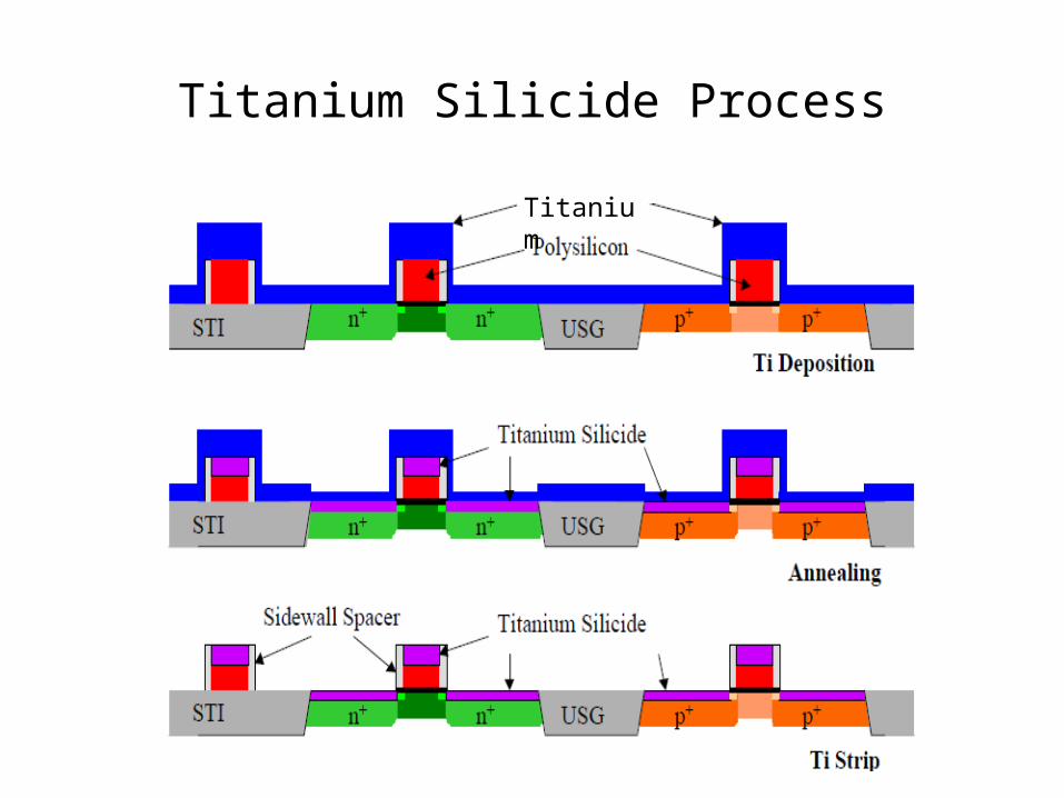
Titanium Silicide Process
Titanium

Aluminum-silicon Alloy
• Form on silicon surface
• Prevent junction spiking due to silicon dissolving in aluminum
Junction Spike

Reflow
• Flowed surface is smoother and flatter• Easier for photolithography and metallization• Higher temperature, better flow result• Reflow time and temperature are determined by
the thermal budget• Higher dopant concentration requires lower flow
temperature

PSG Reflow Process

Reflow
• Undoped silicate glass (USG) becomes soften• at very high temperature T > 1500 °C, will flow• due to the surface tension• • PSG and BPSG become soften at significant• lower temperature (< 1100 °C down to 850 °C)• • Phosphorus also can trap sodium• • PSG and BPSG is commonly used as pre-metal• dielectric (PMD)

Reflow Process• Wafer loading• Temperature ramp-up• Temperature stabilization• Reflow• Temperature ramp-down• Wafer unloading• Reflow usually used N2 ambient• Sometimes H2O vapor is also used• H2O helps to filly oxidize dopant atoms• Smaller device, less thermal budget• No enough thermal budget for reflow for sub-0.25 mm devices• PSG anneal (~750 °C) instead of reflow

Summary of Anneal
• The most commonly used anneal processes are post-implantation annealing, alloy annealing and reflow
• Thermal anneal is required after ion implantation for recover crystal structure and activation dopant atoms
• Thermal anneal helps metal to react with silicon to form silicides