vapor concentration monitor - horiba deposition process benefits of concentration monitoring...
TRANSCRIPT
Vapor Concentration Monitor
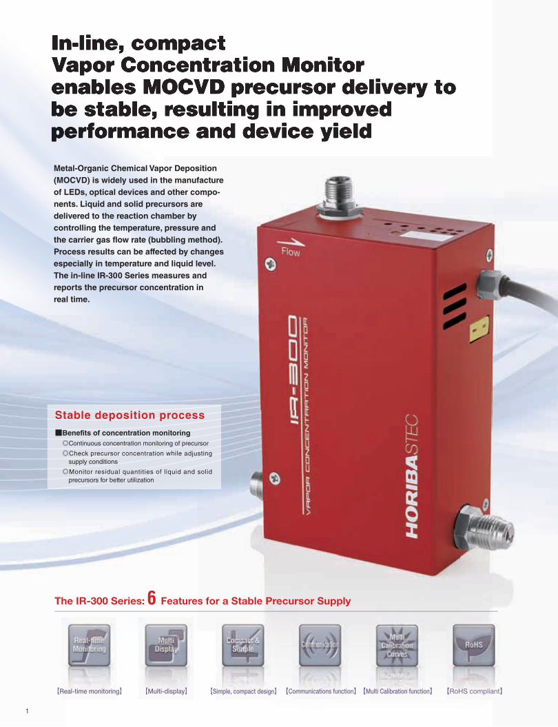
【Real-time monitoring】 【Multi-display】 【Simple, compact design】【Communications function】【Multi Calibration function】 【RoHS compliant】
Stable deposition process
■Benefits of concentration monitoring
◎Continuous concentration monitoring of precursor
◎Check precursor concentration while adjusting
supply conditions
◎Monitor residual quantities of liquid and solid
precursors for better utilization
Metal-Organic Chemical Vapor Deposition
(MOCVD) is widely used in the manufacture
of LEDs, optical devices and other compo-
nents. Liquid and solid precursors are
delivered to the reaction chamber by
controlling the temperature, pressure and
the carrier gas flow rate (bubbling method).
Process results can be affected by changes
especially in temperature and liquid level.
The in-line IR-300 Series measures and
reports the precursor concentration in
real time.
The IR-300 Series: 6 Features for a Stable Precursor Supply
1
Ideal precursor supply through reliable, high-performance vapor concentration monitoring and fluid control backed by a global service support system.
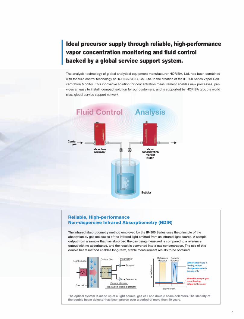
Reliable, High-performance Non-dispersive Infrared Absorptiometry (NDIR)
The infrared absorptiometry method employed by the IR-300 Series uses the principle of the
absorption by gas molecules of the infrared light emitted from an infrared light source. A sample
output from a sample that has absorbed the gas being measured is compared to a reference
output with no absorbance, and the result is converted into a gas concentration. The use of this
double beam method enables long-term, stable measurement results to be obtained.
Light source
Gas cellPyroelectric infrared detector
Reference
Sample
PreamplifierOptical filter
Sensor element
The optical system is made up of a light source, gas cell and double beam detectors. The stability of
the double beam detector has been proven over a period of more than 40 years.
AnalysisFluid Control
When sample gas is
flowing, output
changes on sample
sensor only
Wavelength
When the sample gas
is not flowing,
output is the same
Sampledetector
Referencedetector
Absorb
ance
2
The analysis technology of global analytical equipment manufacturer HORIBA, Ltd. has been combined
with the fluid control technology of HORIBA STEC, Co., Ltd. in the creation of the IR-300 Series Vapor Con-
centration Monitor. This innovative solution for concentration measurement enables new processes, pro-
vides an easy to install, compact solution for our customers, and is supported by HORIBA group's world
class global service support network.
A high optical intensity, long-life source combined with a high-speed signal processor enables the IR-300 Series to achieve
faster, more repeatable responses to changes in precursor concentration (more than two times better than HORIBA prior-
generation technologies), in turn enabling new processes with real-time inline concentration measurement.
* For stable monitoring, zero calibration prior to measurement (at least once per day) is recommended.
Response and repeatability that allow tracking of changes in vapor concentration
Allows for the installation of up to 3 discrete chemical/full scale concentration calibration curves.
Real-time Monitoring
Multi-calibration Curve Function (Optional)
Monitoring Real-time monitoring for a stable
vapor concentration supplyI R - 3 0 0 S e r i e s
This option allows the inclusion of 2 additional calibration curves which are customer-enabled using a digital command.
This multi-calibration capability reduces Total Cost of Ownership through the reduction of discrete part numbers required
and greater flexibility in spares usage, resulting in improved equipment uptime.
0
0.2
0.1
0.3
0.4
0.5
0.6
0.7
0.8
0.9
1
0 5 10 15 20 25 30 35 40 45 50 55 60 65 70 75 858060
80
100
120
140
160
180
200
Concentration (vol.%)
Pressure (kPa)
Time (min)
0
0.5
1
1.5
2
2.5
3
0 5 10 15 20 25 30 35 40 45 50 55 60 65 70 75 8060
80
100
120
140
160
180
200
MFC IR-300
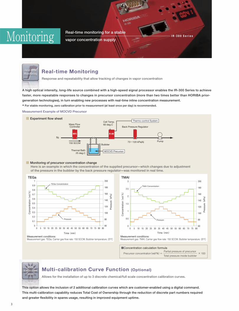
TEGa TMAl
Total pressure inside bubbler
Partial pressure of precursorPrecursor concentration(vol %)= 100×
■Concentration calculation formula
TEGa Concentration
Pressure
TMAI Concentration
Pressure
Measurement Example of MOCVD Precursor
■ Monitoring of precursor concentration change
■ Experiment flow sheet
Concentration (vol.%)
Pressure (kPa)
Time (min)
Mass Flow Controller
Cell Temp. 60 deg.C
Thermal Bath25 deg.C
Bubbler
N2
Back Pressure Regulator
Pump
Thermo-control System
MOCVD Precursor
Measurement conditions:Measurement gas: TEGa, Carrier gas flow rate: 150 SCCM, Bubbler temperature: 25°C
Measurement conditions:Measurement gas: TMAI, Carrier gas flow rate: 150 SCCM, Bubbler temperature: 25°C
150 SCCM 73~120 kPa(A)
Here is an example in which the concentration of the supplied precursor—which changes due to adjustment
of the pressure in the bubbler by the back pressure regulator—was monitored in real time.
3
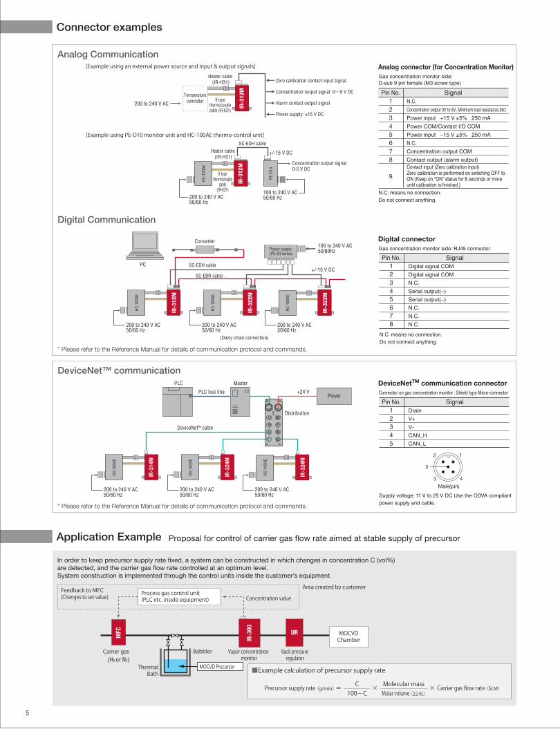
The built-in display and controller units eliminate the need for external or
remote units, enabling more flexible piping configurations and allowing
mounting/design on existing as well as new equipment.
■ Internal structure
The general structure of the product is as shown in the
diagram below. It includes a sensor that measures the
pressure in the gas cell, and a heater for cell heating. This
allows accurate concentration measurement to be performed
through correction of concentration in response to pressure
changes, and stabilization of gas cell temperature.
With a face-to-face size of 124 mm, the unit’s compact
design allows mounting orientation free.
Simple, Compact Design
● DeviceNetTM
Communication Model
● Digital/Analog Communication Model
Detector
1/4 VCR, male
Power source/Communication connector
Pressure sensor
Light source
CPU
Gas cell
Gas inlet
Gas cell block (thermocouple and
cartridge heater
are integrated)
F
D
C
J
F
H
I
A
J
G
B
E
G
Analog connector
Analog communication connector also used to supply
drive power
DeviceNetTM connectorShielded micro-connector for DeviceNetTM
communication use
Indicator LED
NET: Network status
MOD: Node status
Communication speed set switch
To set the communication speed
MAC ID set switchCan be set to any value between 00 and 63MAC ID set switch
Can be set to any value between 00 and 63
Zero calibration switch
To perform zero calibration
Zero calibration switch
To perform zero calibration
Mode LEDIndicates the information being displayed (Conc, kPa or °C)
Mode LEDIndicates the information being displayed (Conc, kPa or °C)
Digital connector
RS-485 communication connector
Display toggle switch
Toggles the display contentD Display toggle switch
Toggles the display content
Display
7-segment indicator that shows concentration
and unit status (pressure, temperature)
E Display
7-segment indicator
that shows concentration
and unit status
(pressure, temperature)
K Output setting switchChanging the number of moving average and the analog output gain value
■ Easy to Set Up for Use with Various Kinds of Gas Supply Lines
Line up includes models for DeviceNetTM and digital/analog communications.
Communications Function
Digital / Analog Communication Model DeviceNetTM Communication Model
The IR-300 Series supports all standard communications protocols for manufacturing devices, such as the open and global field network
DeviceNetTM, and digital/analog communications. The IR-300 Series is ideal for applications ranging from high performance MOCVD process
tools to lab/benchtop experimentation.
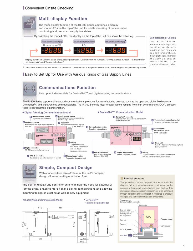
By switching the mode LEDs, the display on the top of the unit can show the following.
The multi-display function of the IR-300 Series combines a display
and mode LEDs on the top of the unit for onsite checking of concentration
monitoring and precursor supply line status.
Multi-display Function
Display current set value or status of adjustable parameters "Calibration curve number", "Moving average number", "Concentration correction gain", and "Analog output gain".
■ Convenient Onsite Checking
T h e I R - 3 0 0 S e r i e s
features a self-diagnostic
f unc t i o n t ha t de tec ts
maximum and minimum
gas cell temperatures,
insufficient light intensity
a n d z e r o c a l i b ra t i o n
e r ro r s and a l e r t s t he
operator with error codes.
Self-diagnostic Function
Vapor concentration display
Conc(ppm, vol%)Gas cell internal pressure display
kPaGas cell temperature display*
℃
124
81.8 150
141.5
141.5
12.7135 151
25.4
50.8
4
OUTPUT
* Differs from the measurement location of the sensor connected to the temperature controller for controlling the temperature of gas cells.
Model
Gas cell optical path length
Target chemical/ full-scale concentration *1
Measurement concentration rangeRepeatability *2Linearity *2Accuracy *3Zero drift *2Response (T90) *4Sensor responseOperating pressure range *2*5Proof PressureOperating flow rate range*2*5Operating ambient temperatureSetting gas cell temperatureGas cell temperature sensorThermal switchWarming up timeWetted materialLeak integrityFittingCommunication type
Powerrequirement
DimensionsMounting orientationMass
Main unitGas cell heater
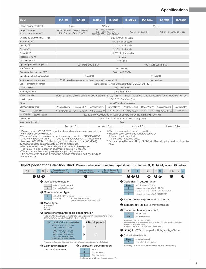
Analog Communication
Digital Communication
[Example using an external power source and input & output signals]
[Example using PE-D10 monitor unit and HC-100AE thermo-control unit]
DeviceNet™ communication
* Please refer to the Reference Manual for details of communication protocol and commands.
* Please refer to the Reference Manual for details of communication protocol and commands.
Analog connector (for Concentration Monitor)
Pin No.12345678
9
SignalN.C.
Concentration output 0V to 5V, Minimum load resistance 2kΩ
Power input +15 V ±5% 250 mA
Power COM/Contact I/O COM
Power input –15 V ±5% 250 mA
N.C.
Concentration output COM
Contact output (alarm output)
Contact input (Zero calibration input)Zero calibration is performed on switching OFF toON (Keep on “ON” status for 6 seconds or more until calibration is finished.)
N.C. means no connection.Do not connect anything.
Gas concentration monitor side: D-sub 9 pin female (M3 screw type)
Pin No.12345678
SignalDigital signal COM
Digital signal COM
N.C.
Serial output(−)
Serial output(−)
N.C.
N.C.
N.C.
N.C. means no connection.Do not connect anything.
Digital connectorGas concentration monitor side: RJ45 connector
Supply voltage: 11 V to 25 V DC Use the ODVA compliantpower supply and cable.
Pin No.12345
SignalDrain
V+
V-
CAN_H
CAN_L
DeviceNetTM communication connectorConnector on gas concentration monitor : Shield type Micro-connector
1
43
2
5
Male(pin)
Temperaturecontroller
IR-312
M
Heater cable (IR-H31)
K typethermocouplecable (IR-K31)
Zero calibration contact input signal
Concentration output signal: 0~5 V DC
Alarm contact output signal
Power supply: ±15 V DC
200 to 240 V AC
HC-1
00AE
IR-312
M
PE-D
10
Heater cable (IR-H31)
SC-EDH cable
Concentration output signal:0-5 V DC
+/-15 V DC
K typethermocouple
cable(IR-K31)
200 to 240 V AC50/60 Hz
100 to 240 V AC50/60 Hz
(Daisy chain connection)
HC-1
00AE
IR-312
M
HC-1
00AE
IR-322
M
HC-1
00AE
IR-322
M100 to 240 V AC50/60HzPower supply
(PE-20 series)
Converter
PC+/-15 V DC
SC-EBR cable
SC-EDH cable
200 to 240 V AC50/60 Hz
200 to 240 V AC50/60 Hz
200 to 240 V AC50/60 Hz
PLC
PLC bus line +24 V
Master
Distribution
DeviceNet™ cable
Power
HC-1
00AE
IR-314M
HC-1
00AE
200 to 240 V AC50/60 Hz
IR-324M
HC-1
00AE
IR-324M
200 to 240 V AC50/60 Hz
200 to 240 V AC50/60 Hz
MFC
(H2 or N2)
IR-300
MOCVDChamber
UR
Concentration value
Area created by customer
Carrier gas
ThermalBath
Vapor concentration monitor
Back pressureregulator
Process gas control unit(PLC etc. inside equipment)
Feedback to MFC(Changes to set value)
Babbler
MOCVD Precursor
Carrier gas flow rate (SLM)Molar volume (22.4L)
Molecular massPrecursor supply rate (g/min) = ××C100-C
■Example calculation of precursor supply rate
SpecificationsConnector examples
Application Example Proposal for control of carrier gas �ow rate aimed at stable supply of precursor
*1 Please contact HORIBA STEC regarding chemical and/or full-scale concentration other than those shown above.
*2 The specification is guaranteed under the standard conditions of HORIBA STEC.Ambient temperature: 23 ± 2℃ / Gas cell temperature: 60℃ / Measurement flow rate: 1000 SCCM / Calibration gas: C3H8 balanced in N2 at 105 KPa (A).
*3 Accuracy is based on concentration of the calibration gas.*4 Gas replacement time (Td: time delay) is not included in the response.
The typical Td in our inspection equipment is approx. 1.0 second. ※The response without moving average is approx. 1.5 seconds.
It is necessary to change # of moving average of firmware settings by digital communication.
*5 This is recommended operating condition.*6 Required specification of temperature controller
PID operation by auto tuningControl cycle : 1 second or less
*7 Optional wetted Material : Body ; SUS-316L, Gas cell optical window ; Sapphire, Ni, Al
In order to keep precursor supply rate �xed, a system can be constructed in which changes in concentration C (vol%) are detected, and the carrier gas �ow rate controlled at an optimum level.System construction is implemented through the control units inside the customer’s equipment.
5 6
5mm
TMGa / 25 vol% , DEZn / 10 vol%IPA / 5 vol% , IPA / 10 vol% GeH4 1vol%/H2 B2H6 10vol%/H2 or He
0 to 100% of full scale
≤±0.5% of full scale
≤±1.0% of full scale
≤±1.0% of full scale
≤±1.0% of full scale/day
≤ 4 sec
≤ 0.4 sec
500 kPa (A)
50 to 1000 SCCM
Thermocouple K Type (Connector type: OMEGA SMP-K-F)
100℃ (self-hold)
More than 1 hour
≤ 5×10–¹² Pa・m³/s (He)
1/4 VCR male or equivalent
200 to 240 V AC/Max. 50 VA (Connector type: Molex Standard .093 1545-P1)
124 x 50.8 x 135 mm exception of projection
Free
100 kPa to 300 kPa (A)30 kPa to 300 kPa (A)
20 to 35℃15 to 35℃
Non heating60 ℃ (Need temperature controller prepared by users )*6
Body:SUS316L、Gas cell optical window:sapphire、Ni 、AlBody: SUS316L, Gas cell optical window: Sapphire, Ag, Cu, Ti, Ni *7
IR-312M IR-314M IR-324MIR-322M IR-322MA IR-324MA IR-324MBIR-322MB
Analog/Digital
±15 V DC/3.8 W
Approx.1.2 kg Approx.1.2 kg Approx.1.5 kgApprox.1.5 kg
DeviceNet™
24 V DC/12 W
Analog/Digital
±15 V DC/3.8 W
DeviceNet™
24 V DC/12 W
Analog/ Digital
±15 VDC / 3.8 W
DeviceNet™
24 V DC/12 W
Analog/ Digital
±15 VDC / 3.8 W
DeviceNet™
24 V DC/12 W
50mm 50mmTMln / 1 vol% , TMIn / 2.5 vol% , TEGa / 1 vol% , TMGa / 1 vol%
TMAI / 2 vol% , DEZn / 2.5 vol% , IPA / 1 vol%
IR-3 4 M , Target chemical 1/full scale concentration , Target chemical 2/
full scale concentration , Target chemical 3/full scale concentration , T 1 3 , 200 K A60 , ,4CRL1
1 2 3 4 5 6 7 8 9 10 11 12
Type/Specification Selection Chart: Please make selections from specification columns ❷, ❹, ❻, ❼, ,and below.
● Cell window blazing12Blank
A
Ag blazing (standard)Kovar with Ni Coating (option)
● Heater power requirement : 200-240 V AC8
● Temperature sensor : K type thermocouple9
● Heater set temperature : 60℃10
● Fitting : 1/4VCR male or equivalent, Fitting to fitting = 124 mm11
● DeviceNet™ output range7Blank
1
3
5
Other than DeviceNet™ modelConcentration output full scale "100%F.S."Concentration output full scale "133%F.S." (standard)Concentration output full scale "133.329%F.S."
60℃ (Standard)Non-heated (Option)*
● Connector location : Top-side of the monitor5
● Gas cell specification11
2
5 mm optical path length cell50 mm optical path length cell
M:StandardMA:GeH4MB:B2H6
*4 If selecting DeviceNet™, please choose an output scope from ❼.
● Communication type22
4
Analog & RS-485/F-net Protocol DeviceNet™
● Model type3
Please select the desired target chemical and full scale concentration (×1 for standard, ×2 for option).This determines the gas cell specification (IR-31 or IR-32) in ❶.
● Target chemical/full scale concentration4
1
2
Target chemical/full scale concentrationTMGa / 25 vol% , DEZn / 10 vol%
IPA / 5 vol% , IPA / 10 vol%
Please contact us regarding target chemicals/full scale concentrations not listed above.
TMln / 1 vol% , TMIn / 2.5 vol%TEGa / 1 vol% , TMGa / 1 vol%
TMAI / 2 vol% , DEZn / 2.5 vol%IPA / 1 vol% , GeH4/H2 1vol%
B2H6/H2 10vol% , B2H6/He 10vol%
● Gas cell specification1
60
AMB
*Available for IPA 1 vol% and 5 vol%Ambient temperature fluctuation must be within ±1℃, otherwise concentration accuracy is out of guarantee.*If selecting MA or MB from ③ Please choose AMB.
*If selecting MA or MB from ③ Please choose A (Kovar with Ni coating)
*If selecting MA or MB from ③ please choose "1".
● Calibration curve number:61
2
3
One typeTwo types (option)Three types (option)
Model
Gas cell optical path length
Target chemical/ full-scale concentration *1
Measurement concentration rangeRepeatability *2Linearity *2Accuracy *3Zero drift *2Response (T90) *4Sensor responseOperating pressure range *2*5Proof PressureOperating flow rate range*2*5Operating ambient temperatureSetting gas cell temperatureGas cell temperature sensorThermal switchWarming up timeWetted materialLeak integrityFittingCommunication type
Powerrequirement
DimensionsMounting orientationMass
Main unitGas cell heater
Analog Communication
Digital Communication
[Example using an external power source and input & output signals]
[Example using PE-D10 monitor unit and HC-100AE thermo-control unit]
DeviceNet™ communication
* Please refer to the Reference Manual for details of communication protocol and commands.
* Please refer to the Reference Manual for details of communication protocol and commands.
Analog connector (for Concentration Monitor)
Pin No.12345678
9
SignalN.C.
Concentration output 0V to 5V, Minimum load resistance 2kΩ
Power input +15 V ±5% 250 mA
Power COM/Contact I/O COM
Power input –15 V ±5% 250 mA
N.C.
Concentration output COM
Contact output (alarm output)
Contact input (Zero calibration input)Zero calibration is performed on switching OFF toON (Keep on “ON” status for 6 seconds or more until calibration is finished.)
N.C. means no connection.Do not connect anything.
Gas concentration monitor side: D-sub 9 pin female (M3 screw type)
Pin No.12345678
SignalDigital signal COM
Digital signal COM
N.C.
Serial output(−)
Serial output(−)
N.C.
N.C.
N.C.
N.C. means no connection.Do not connect anything.
Digital connectorGas concentration monitor side: RJ45 connector
Supply voltage: 11 V to 25 V DC Use the ODVA compliantpower supply and cable.
Pin No.12345
SignalDrain
V+
V-
CAN_H
CAN_L
DeviceNetTM communication connectorConnector on gas concentration monitor : Shield type Micro-connector
1
43
2
5
Male(pin)
Temperaturecontroller
IR-312
M
Heater cable (IR-H31)
K typethermocouplecable (IR-K31)
Zero calibration contact input signal
Concentration output signal: 0~5 V DC
Alarm contact output signal
Power supply: ±15 V DC
200 to 240 V AC
HC-1
00AE
IR-312
M
PE-D
10
Heater cable (IR-H31)
SC-EDH cable
Concentration output signal:0-5 V DC
+/-15 V DC
K typethermocouple
cable(IR-K31)
200 to 240 V AC50/60 Hz
100 to 240 V AC50/60 Hz
(Daisy chain connection)
HC-1
00AE
IR-312
M
HC-1
00AE
IR-322
M
HC-1
00AE
IR-322
M
100 to 240 V AC50/60HzPower supply
(PE-20 series)
Converter
PC+/-15 V DC
SC-EBR cable
SC-EDH cable
200 to 240 V AC50/60 Hz
200 to 240 V AC50/60 Hz
200 to 240 V AC50/60 Hz
PLC
PLC bus line +24 V
Master
Distribution
DeviceNet™ cable
Power
HC-1
00AE
IR-314M
HC-1
00AE
200 to 240 V AC50/60 Hz
IR-324M
HC-1
00AE
IR-324M
200 to 240 V AC50/60 Hz
200 to 240 V AC50/60 Hz
MFC
(H2 or N2)
IR-300
MOCVDChamber
UR
Concentration value
Area created by customer
Carrier gas
ThermalBath
Vapor concentration monitor
Back pressureregulator
Process gas control unit(PLC etc. inside equipment)
Feedback to MFC(Changes to set value)
Babbler
MOCVD Precursor
Carrier gas flow rate (SLM)Molar volume (22.4L)
Molecular massPrecursor supply rate (g/min) = ××C100-C
■Example calculation of precursor supply rate
SpecificationsConnector examples
Application Example Proposal for control of carrier gas �ow rate aimed at stable supply of precursor
*1 Please contact HORIBA STEC regarding chemical and/or full-scale concentration other than those shown above.
*2 The specification is guaranteed under the standard conditions of HORIBA STEC.Ambient temperature: 23 ± 2℃ / Gas cell temperature: 60℃ / Measurement flow rate: 1000 SCCM / Calibration gas: C3H8 balanced in N2 at 105 KPa (A).
*3 Accuracy is based on concentration of the calibration gas.*4 Gas replacement time (Td: time delay) is not included in the response.
The typical Td in our inspection equipment is approx. 1.0 second. ※The response without moving average is approx. 1.5 seconds.
It is necessary to change # of moving average of firmware settings by digital communication.
*5 This is recommended operating condition.*6 Required specification of temperature controller
PID operation by auto tuningControl cycle : 1 second or less
*7 Optional wetted Material : Body ; SUS-316L, Gas cell optical window ; Sapphire, Ni, Al
In order to keep precursor supply rate �xed, a system can be constructed in which changes in concentration C (vol%) are detected, and the carrier gas �ow rate controlled at an optimum level.System construction is implemented through the control units inside the customer’s equipment.
5 6
5mm
TMGa / 25 vol% , DEZn / 10 vol%IPA / 5 vol% , IPA / 10 vol% GeH4 1vol%/H2 B2H6 10vol%/H2 or He
0 to 100% of full scale
≤±0.5% of full scale
≤±1.0% of full scale
≤±1.0% of full scale
≤±1.0% of full scale/day
≤ 4 sec
≤ 0.4 sec
500 kPa (A)
50 to 1000 SCCM
Thermocouple K Type (Connector type: OMEGA SMP-K-F)
100℃ (self-hold)
More than 1 hour
≤ 5×10–¹² Pa・m³/s (He)
1/4 VCR male or equivalent
200 to 240 V AC/Max. 50 VA (Connector type: Molex Standard .093 1545-P1)
124 x 50.8 x 135 mm exception of projection
Free
100 kPa to 300 kPa (A)30 kPa to 300 kPa (A)
20 to 35℃15 to 35℃
Non heating60 ℃ (Need temperature controller prepared by users )*6
Body:SUS316L、Gas cell optical window:sapphire、Ni 、AlBody: SUS316L, Gas cell optical window: Sapphire, Ag, Cu, Ti, Ni *7
IR-312M IR-314M IR-324MIR-322M IR-322MA IR-324MA IR-324MBIR-322MB
Analog/Digital
±15 V DC/3.8 W
Approx.1.2 kg Approx.1.2 kg Approx.1.5 kgApprox.1.5 kg
DeviceNet™
24 V DC/12 W
Analog/Digital
±15 V DC/3.8 W
DeviceNet™
24 V DC/12 W
Analog/ Digital
±15 VDC / 3.8 W
DeviceNet™
24 V DC/12 W
Analog/ Digital
±15 VDC / 3.8 W
DeviceNet™
24 V DC/12 W
50mm 50mmTMln / 1 vol% , TMIn / 2.5 vol% , TEGa / 1 vol% , TMGa / 1 vol%
TMAI / 2 vol% , DEZn / 2.5 vol% , IPA / 1 vol%
IR-3 4 M , Target chemical 1/full scale concentration , Target chemical 2/
full scale concentration , Target chemical 3/full scale concentration , T 1 3 , 200 K A60 , ,4CRL1
1 2 3 4 5 6 7 8 9 10 11 12
Type/Specification Selection Chart: Please make selections from specification columns ❷, ❹, ❻, ❼, ,and below.
● Cell window blazing12Blank
A
Ag blazing (standard)Kovar with Ni Coating (option)
● Heater power requirement : 200-240 V AC8
● Temperature sensor : K type thermocouple9
● Heater set temperature : 60℃10
● Fitting : 1/4VCR male or equivalent, Fitting to fitting = 124 mm11
● DeviceNet™ output range7Blank
1
3
5
Other than DeviceNet™ modelConcentration output full scale "100%F.S."Concentration output full scale "133%F.S." (standard)Concentration output full scale "133.329%F.S."
60℃ (Standard)Non-heated (Option)*
● Connector location : Top-side of the monitor5
● Gas cell specification11
2
5 mm optical path length cell50 mm optical path length cell
M:StandardMA:GeH4MB:B2H6
*4 If selecting DeviceNet™, please choose an output scope from ❼.
● Communication type22
4
Analog & RS-485/F-net Protocol DeviceNet™
● Model type3
Please select the desired target chemical and full scale concentration (×1 for standard, ×2 for option).This determines the gas cell specification (IR-31 or IR-32) in ❶.
● Target chemical/full scale concentration4
1
2
Target chemical/full scale concentrationTMGa / 25 vol% , DEZn / 10 vol%
IPA / 5 vol% , IPA / 10 vol%
Please contact us regarding target chemicals/full scale concentrations not listed above.
TMln / 1 vol% , TMIn / 2.5 vol%TEGa / 1 vol% , TMGa / 1 vol%
TMAI / 2 vol% , DEZn / 2.5 vol%IPA / 1 vol% , GeH4/H2 1vol%
B2H6/H2 10vol% , B2H6/He 10vol%
● Gas cell specification1
60
AMB
*Available for IPA 1 vol% and 5 vol%Ambient temperature fluctuation must be within ±1℃, otherwise concentration accuracy is out of guarantee.*If selecting MA or MB from ③ Please choose AMB.
*If selecting MA or MB from ③ Please choose A (Kovar with Ni coating)
*If selecting MA or MB from ③ please choose "1".
● Calibration curve number:61
2
3
One typeTwo types (option)Three types (option)
Printed in Japan 1506SK13IR3-HE
http://www.horiba-stec.jp/e.
Please read the operation manual before using this product to ensure safe and proper handling of the product.
●The contents of this catalog are subject to change without prior notice, and without any subsequent liability to this company.●It is strictly forbidden to copy the content of this catalog in part or in full.●All brand names, product names and service names in this catalog are trademarks or registered trademarks of their respective companies.●DeviceNet is the trademark of Open Device Net Vendors Association, lnc.
Global Support
World-wide Network
TAIWANHORIBA Taiwan, Inc.
U.S.A.HORIBA Instruments Incorporated
KOREAHORIBA STEC Korea, Ltd.
U.K.HORIBA UK Limited
FRANCEHORIBA France Sarl, Grenoble Office
GERMANYHORIBA Europe GmbH
SINGAPOREHORIBA Instruments (Singapore) Pte. Ltd.
CHINAHORIBA (China) Trading Co., Ltd.
SINGAPORE
CHINA
TAIWAN
KOREA
U.K.
GERMANYFRANCE
U.S.A.