chapter 8 multidisciplinary coupling analysis and design · 2018-01-12 · chapter 8...
TRANSCRIPT
Chapter 8Multidisciplinary Coupling Analysisand Design
8.1 Conjugate Heat Transfer Problems
8.1.1 Conjugate Heat Transfer in Turbines
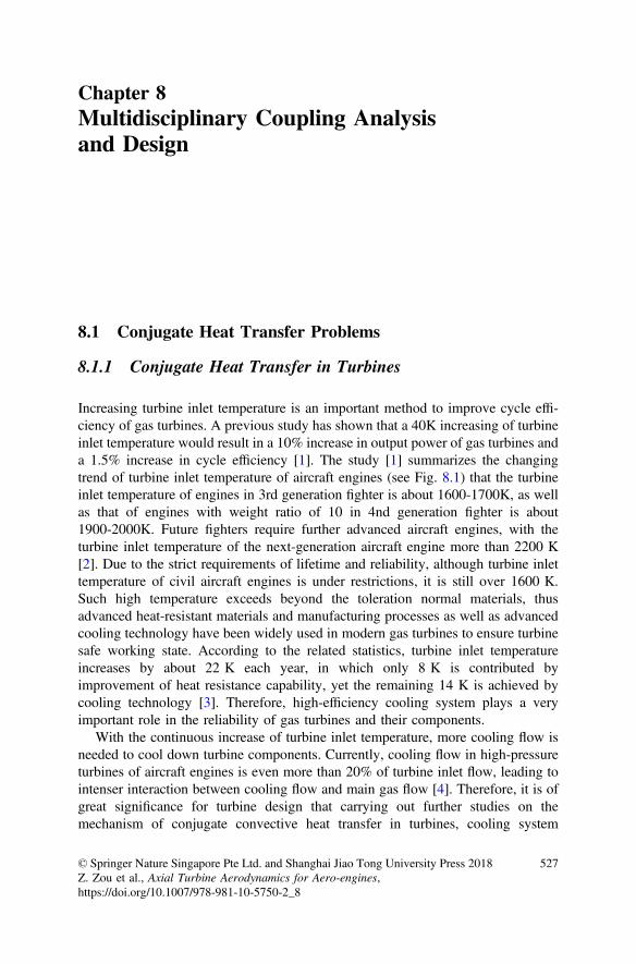
Increasing turbine inlet temperature is an important method to improve cycle effi-ciency of gas turbines. A previous study has shown that a 40K increasing of turbineinlet temperature would result in a 10% increase in output power of gas turbines anda 1.5% increase in cycle efficiency [1]. The study [1] summarizes the changingtrend of turbine inlet temperature of aircraft engines (see Fig. 8.1) that the turbineinlet temperature of engines in 3rd generation fighter is about 1600-1700K, as wellas that of engines with weight ratio of 10 in 4nd generation fighter is about1900-2000K. Future fighters require further advanced aircraft engines, with theturbine inlet temperature of the next-generation aircraft engine more than 2200 K[2]. Due to the strict requirements of lifetime and reliability, although turbine inlettemperature of civil aircraft engines is under restrictions, it is still over 1600 K.Such high temperature exceeds beyond the toleration normal materials, thusadvanced heat-resistant materials and manufacturing processes as well as advancedcooling technology have been widely used in modern gas turbines to ensure turbinesafe working state. According to the related statistics, turbine inlet temperatureincreases by about 22 K each year, in which only 8 K is contributed byimprovement of heat resistance capability, yet the remaining 14 K is achieved bycooling technology [3]. Therefore, high-efficiency cooling system plays a veryimportant role in the reliability of gas turbines and their components.
With the continuous increase of turbine inlet temperature, more cooling flow isneeded to cool down turbine components. Currently, cooling flow in high-pressureturbines of aircraft engines is even more than 20% of turbine inlet flow, leading tointenser interaction between cooling flow and main gas flow [4]. Therefore, it is ofgreat significance for turbine design that carrying out further studies on themechanism of conjugate convective heat transfer in turbines, cooling system
© Springer Nature Singapore Pte Ltd. and Shanghai Jiao Tong University Press 2018Z. Zou et al., Axial Turbine Aerodynamics for Aero-engines,https://doi.org/10.1007/978-981-10-5750-2_8
527

optimization, and cooling flow reduction AITEB (Aero-thermal Investigations ofTurbine Endwalls and Blades) program was carried out in the Sixth FrameworkProgramme (2003) of the EU with the aim of researching on the aero-thermalcharacteristics of turbine endwalls and blades with high lift and high exit Machnumber, as well as developing advanced cooling technology, etc. [5]. Figure 8.2shows the typical turbine blade cooling system [6]. In this system, the temperaturedistribution and thermal stress in blades are determined by both flow condition andinteraction of cooling flow and external gas flow. Heat conduction at the solid-wallboundary layer has influence on local heat transfer parameters and flow charac-teristics as well as the interaction between the cooling flow and the main flow maychange the aerodynamic mixing loss in turbines. This interaction between the fluid
Fig. 8.1 Trend of turbine inlet temperature [1]
Fig. 8.2 Diagram of a typical turbine blade cooling system [6]
528 8 Multidisciplinary Coupling Analysis and Design
and the solid domain lead to the conjugate heat transfer problem. Only with fullyconsidering and characterizing the interaction between the temperature field and theflow field can we obtain the correct thermal loads of turbine components and theflow structure which is more consistent with the reality.
8.1.2 Research Methods for Aerodynamic-Heat TransferCoupling in Turbines
8.1.2.1 Traditional Non-conjugate Numerical Research Methodsfor Aerodynamic-Heat Transfer Coupling
In early stage, fluid network and boundary layer calculation programs were gen-erally used in engineering design to evaluate a convective heat transfer evaluationof turbines and cooling system [7, 8]. Based on the fluid network method, thecomplex flow passage of flow system is simplified into a network system composedby nodes and components, then the pressure, temperature, flow rate and otherparameters could be calculated by solving the non-linear equations which areestablished by topology of the network. Boundary layer calculation programs couldobtain external heat transfer coefficient of turbine blades by solvingtwo-dimensional boundary layer equations, for instance, the famous STAN5 pro-gram is widely used in engineering design, which solves the parabolized turbulentboundary layer equations by Patankar-Spalding finite difference scheme to acquireflow and heat transfer parameters. This boundary layer calculation method issuitable for evaluating the thermal loads on the middle of blades and other com-ponents where the flow has obvious two-dimensional characteristics and smallpressure gradient, However, error would increase significantly if shock waves andcomplex endwall flows exist.
With the development of computing method and capacity, CFD method has alsobeen used in thermal analysis of turbines. CFD model can simulate and describe thethree-dimensional flow field structure in detail, thus the CFD method can be used toobtain the heat transfer parameters closely related to flow conditions. These casesare called non-conjugate computing method, in which first boundary conditions aregenerally used to define wall temperature distribution then to obtain local heat fluxdensity. For example, Ameri, Bunker, Saha, etc. worked out the convective heattransfer coefficient distribution at the blade tip through CFD with the boundarycondition of adiabatic wall and isothermal wall. Roy obtained the convective heattransfer coefficient distribution on the surface of a rotor disk using this method,indicating that flow structure in the disk cavity has significant effect on the thermalload of rotor disk [9–11]. Similarly, this method has also been widely used inresearching the influence of the hub-endwall thermal load and inlet hot spots onheat transfer [12, 13]. If more accurate temperature distribution is needed, the
8.1 Conjugate Heat Transfer Problems 529

equations could be further solved by adding the convective heat transfer informa-tion on the surface to a solid heat transfer solver, as well as forming an externaliteration combining CFD and heat conduction calculations to consider the conjugateheat transfer problems, so as to improve the prediction accuracy of temperaturedistribution.
Especially, the selection of reference temperature, which is generally based onexperience, would make a difference to the results in non-conjugate calculation.Furthermore, the boundary parameters selection are generally based on the dataaccumulated through long-term studies. Particularly when the flow structure iscomplex or heat conduction itself would influence heat transfer parameters, it wouldbe hard to give appropriate and accurate boundary conditions thus the accuracywould be degraded greatly. In these cases, the results may misguide designers, so itis necessary to analyze them carefully [14].
8.1.2.2 Conjugate Heat Transfer Numerical Methods
Conjugate Heat transfer (CHT) method, which is used to calculate the heat transferand solid heat conduction simultaneously, could make the thermal analysis beindependent of the selection of reference temperature, thus to achieve a moreaccurate thermal load distribution. Generally, there are two methods to solve theconjugate heat transfer problem. One is global discretization and solution andanother is local solution and boundary coupling. With respect to the first method,heat transfer processes in different areas are combined into an unified heat transferprocess and the general governing equations are used for both the fluid and the soliddomains, in which the only difference occurs in terms of generalized diffusioncoefficients(viscosity coefficient and coefficient of heat conduction) and generalizedsource terms, moreover, the interface between the fluid and the solid would beincluded of the inner part of the computational domain. When solving discreteequations by the finite volume methods, the continuity condition on the interfacecould be satisfied generally. NASA’s Glenn-HT (CHT) solver, using this compu-tational method which sets solid density as a constant solves as well as simplifiesenergy equation with the solid velocity of 0, while the discretization method andnumerical method are consistant for both the fluid domain and the solid domain[15]. However, the computing stability would be influenced by this method becausethat the flux and gradient on the interface is so hard to calculate accurately, whichcould be different with thousands of times at the two sides of the flow structureinterface [16]. For another method, the solution is carried out respectively in boththe fluid domain and the solid domain. The N-S equations are solved in the fluiddomain while temperature field is determined by solving heat conduction equationsin the solid domain. Temperature, heat flux, and other information are then trans-mitted through the interface between the fluid domain and the solid domain to linkthe fluid them together. This method can make full use of the existinghigh-precision CFD solvers with good stability, so it is widely used in turboma-chinery conjugate heat transfer studies (such as the famous CHT-Flow solver) [17].
530 8 Multidisciplinary Coupling Analysis and Design

Conjugate heat transfer calculations, involving flow field and temperature field,have strict demands on the accuracy of flow simulation, conjugation methods, aswell as computational models, thus it is necessary to carefully analyze factors whichinfluences the accuracy of the calculations. The relevant studies in China, Li, Zou,et al. (Beihang University) studied on the influence of different turbulence modelparameters and transition models on numerical results of conjugate heat transfersimulation using the experimental database of the MarkII inner-cooling turbinecascade, and obtained the limiter which is suitable for Chien k-e model by analysisand derivation, then developed a three dimensional conjugate heat transfer solverbased on preprocessing methods, which has satisfactory accuracy [18, 19]. Li et al.[20] (Harbin Institute of Technology) did a series of meaningful work on conjugatethermal-flow-elastic multi-field numerical simulation and then developed a platformbased on finite difference method for conjugate thermal-flow-elastic multi-fieldnumerical simulation. Aiming at porous medium-based transpiration coolingstructure analysis, Zhang, Zou, et al. established a 3D numerical simulation methodfor conjugate porous/fluid/solid domains, which could serve as a simulation tool forstudies on advanced transpiration cooling technology and porous cooling tech-nology for high-speed aircrafts [21, 22].
However, the current 3D conjugate heat transfer computational methods cannotbe directly used in engineering design due to their insufficient predictive ability andlimited precision, in which the influence factors on simulation accuracy is various.Firstly, it is difficult for the turbulence model to accurately simulate the influence offlow phenomena (transition, separation, etc.) and roughness of solid wall surface,which have significant influence on heat transfer. Secondly it is difficult to obtainaccurate and detailed aero-thermodynamic and geometric boundary conditions. Inaddition, other factors, such as numerical simulation methods, grid, etc., could alsolead to uncertainty of the results [23, 24]. Because of the above reasons, results ofthe current 3-D conjugate heat transfer calculations have to be only a reference basisfor analysis, as well as be interpreted carefully and cannot be trusted blindly.
8.1.2.3 Experimental Methods for Aerodynamic-Heat TransferCoupling in Turbines
Because of the limitations of turbines thermal analysis methods in terms of preci-sion and convergence. The experiment is still an important method for studyingaerodynamic heat transfer, so as to check the numerical simulation methods, as wellas to study the mechanism of conjugate heat transfer, to establish physical models,and to assess design schemes. The measurement of temperature field is veryimportant for turbine CHT experiments, in which the commonly used methodsincludes contact measurement techniques (using thermocouples, etc.) and
8.1 Conjugate Heat Transfer Problems 531

non-contact measurement techniques (such as, liquid crystal thermography, infraredthermometry, etc.) [4, 25–27]. Figure 8.3 shows the typical techniques used inturbine aerodynamic heat transfer experiments.
It is worth noting that, it is generally difficult for gas turbines to carry out theresults under real working conditions due to the limitations of experiment condi-tions and test equipments. Thus, similar flow conditions are used in most of theexperiments to simulate real flows in turbines with the condition of normal ormedium temperature. Under this condition, the similarity criteria used in theexperiments are of great significance to the experimental results, and it is a keypoint that using the similarity criteria to model the boundary conditions. In addition,it is of great importance for further understanding of the mechanism of conjugateheat transfer and diagnosis design by developing the advanced test methods andtechnologies under the condition of little disturbance to test flow field.
Fig. 8.3 Techniques used in turbine aerodynamic-heat transfer measurements [25, 27].a Thermocouple techniques, b Liquid crystal thermography, c Infrared thermometry, d Heattransfer coefficient distribution in a ITD
532 8 Multidisciplinary Coupling Analysis and Design

8.1.3 Mechanism of Interaction Between Flow Fieldand Temperature Field in Turbines
Flow field and temperature field in turbines are highly conjugate and closelyinteracted. On the one hand, complex flow structures in turbines such as shockwaves, secondary vortexes, leakage flows, and sealing/cooling jet flows have sig-nificant influence on heat transfer characteristic and thermal load of these compo-nents. On the other hand, flow structures and turbine performance are influenced byboundary heat transfer in the fluid domain, as well as interaction between coolingoutflow and the main flow, etc. Therefore, it is very important to analyze themechanism of interaction between flow field and temperature field from these twoaspects. The interaction between cooling flow and the main flow has been presentedin Chap. 2, and the repetition is saved here.
Adiabatic wall assumption, which is considered that heat transfer has no influ-ence on turbines’ aerodynamic performance, is usually used in traditional turbo-machinery design and flow mechanism study. Generally, this assumption iscoincident for most of turbomachineries. However, the assumption not alwaysappropriate in some gas turbines, such as micro-turbines, high cooling flow tur-bines, etc., in which influence of heat transfer at solid wall boundary on flows andperformance is non-negligible. For example, as for boundary layer flows, a previousstudy has shown that thermal environment has very significant influence onspace-time evolution characteristics of boundary layers that wall heating or coolingwould directly make a influence on the transition process of boundary layers,advancing or delaying the transition and further influencing turbine flows andperformance. On the other hand, flow structures would also effect the heat transferon the wall surface, and thus the interaction between flow and wall surface lead tothe highly conjugate problem [28]. Using the DNS method, Wu et al. studied thesmall-scale vortex structures in the flat plate transitional boundary layer and tur-bulent boundary layer with heat transfer and obtained coherent structures in theheating boundary layer (as shown in Fig. 8.4). As the results, turbulent spots in thetransition zone are fully filled with closely distributed and relatively isolated hairpinvortexes, which would move downstream with the turbulent spots and enter thedownstream turbulent boundary layer, changing with heating condition, then itwould change these coherent structures [29]. Shafi et al. and Krogstad et al. [30, 31]gained the similar conclusions. In addition, in low-velocity gas flows, the buoyancylift caused by temperature gradient is also an important driving force, thus theinfluence of boundary temperature on flows must be considered particularly instudies of internal flows in cooled turbine blades [32].
There are several flow phenomena (transition, separation, etc.) and some complexflow structures (shock waves, secondary vortexes, etc.) in turbines, which have signifi-cant influence on heat transfer characteristics and temperature field. Giel et al. [33] fromNASA analyzed the influence of flows in blade passage on surface heat transfer ofturbine blades by liquid crystal thermography and other techniques. Figure 8.5 shows theStanton Number distribution on blade surface. On the suction surface, the Stanton
8.1 Conjugate Heat Transfer Problems 533
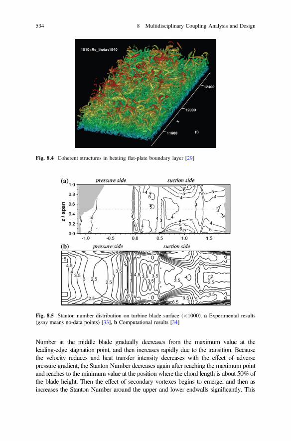
Number at the middle blade gradually decreases from the maximum value at theleading-edge stagnation point, and then increases rapidly due to the transition. Becausethe velocity reduces and heat transfer intensity decreases with the effect of adversepressure gradient, the Stanton Number decreases again after reaching the maximum pointand reaches to the minimum value at the position where the chord length is about 50% ofthe blade height. Then the effect of secondary vortexes begins to emerge, and then asincreases the Stanton Number around the upper and lower endwalls significantly. This
Fig. 8.4 Coherent structures in heating flat-plate boundary layer [29]
Fig. 8.5 Stanton number distribution on turbine blade surface (�1000). a Experimental results(gray means no-data points) [33], b Computational results [34]
534 8 Multidisciplinary Coupling Analysis and Design
region expands gradually to the middle of the blade with the migration of passagevortexes. At the position where the chord length is 130% of the blade height, the obliqueshock wave formed at the outlet of adjacent blades results in the interaction betweenshock wave and boundary layer on the suction surface, which increases the thickness ofthe boundary layer gradually, and as a result, the Stanton Number decreases again. As theinfluence of shock waves weakens at the downstream endwall region, the effect ofsecondary flows increases rapidly, and regions with intensive heat transfer appear againaround the upper and lower endwalls.
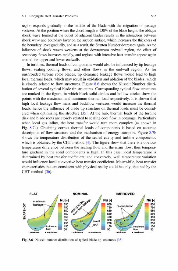
In turbines, thermal loads of components would also be influenced by tip leakageflows, sealing cooling flows, and other flows in the endwall region. As forunshrouded turbine rotor blades, tip clearance leakage flows would lead to highlocal thermal loads, which may result in oxidation and ablation of the blades, whichis closely related to flow structures. Figure 8.6 shows the Nusselt Number distri-bution of several typical blade tip structures. Corresponding typical flow structuresare marked in the figure, in which black solid circles and hollow circles show thepoints with the maximum and minimum thermal load respectively. It is shown thathigh local leakage flow mass and backflow vortexes would increase the thermalloads, hence the influence of blade tip structure on thermal loads must be consid-ered when optimizing the structure [35]. At the hub, thermal loads of the turbinedisk and blade roots are closely related to sealing cool flow in obturage. Particularlywhen local gas influx, the heat transfer would turn more complex (as shown inFig. 8.7a). Obtaining correct thermal loads of components is based on accuratedescription of flow structure and the mechanism of energy transport. Figure 8.7bshows the temperature distribution of the sealed cavity and turbine components,which is obtained by the CHT method [4]. The figure show that there is a obvioustemperature difference between the sealing flow and the main flow, thus tempera-ture gradient in the solid components is high. In this case, local temperature isdetermined by heat transfer coefficient, and conversely, wall temperature variationwould influence local convective heat transfer coefficient. Meanwhile, heat transfercharacteristics that are consistent with physical reality could be only obtained by theCHT method [36].
Fig. 8.6 Nusselt number distribution of typical blade tip structures [35]
8.1 Conjugate Heat Transfer Problems 535

8.2 Flow-Structure Interaction Problems
8.2.1 Flow-Structure Interaction Problem in Turbines
The working principle of a turbine results in the intense interaction between thesolid in a turbine and the fluid in it. Because the internal flow field is unsteadyessentially, hence the force applied on the surface of blades and other solid com-ponents is also unsteady, which may result in blade vibration. Conversely, bladedeformation or vibration may lead to unsteady changes of boundary conditions ofthe flow field which may affect the flow graphs and the interaction between the fluidand the solid. Thus it can be seen that the conjugate problem between the flow andstructure is inevitable.
The interactive relations between various forces in the generalized conjugateprocess between the fluid and the solid are described in Fig. 8.8 [37]. The processhas the basic characteristic that both the interaction between the flow aerodynamicand solid movement are realized through the conjugate interfaces. In addition, bothaerodynamic forces and solid movements at the interfaces are determined specifi-cally by solving the entire conjugate system systematically, which could beunknown presciently.
According to the discipline classification, the sub-discipline dealing with thefluid-structure interaction problem in turbomachinery is generally called turboma-chinery aeroelasticity. According to the response patterns of blade, turbomachineryaeroelasticity problems can be generally divided into static aeroelasticity problems,forced response, and flutter [38]. Generally, the static aeroelasticity discuss theelastic deformation of structures. for example the deformation, which is differentfrom original cold-state shapes, of blade with the centrifugal force and aerodynamicforce. The deformation is static and generally independent from vibration, and theeffect of static aeroelasticity on performance of turbine components can be inhibitedby back-stepping the geometrical machining parameters as well as by machining
(a) Diagram of sealed cavity flow structures (b) Temperature distribution
Fig. 8.7 Typical sealed cavity flow structures and temperature distribution [4]
536 8 Multidisciplinary Coupling Analysis and Design

and assembly. For example, pre-twisting and other methods are often used ininstallation of typical low-pressure turbine blades with high aspect ratio so as toeliminate this effect. Because the deformation changes linearly with different rotatespeed the effect of blade deformation should be considered in evaluating the per-formance at off-design rotate speed. For example, Wilson et al. [39] studied theeffect of the large fan blade elastic deformation at different speeds on performanceby using a non-linear model. Forced response generally refers to the structuralvibration of blades, which is caused by periodic unsteady aerodynamic force whenthe blades pass through the upstream blade row wake region or the blade rowpotential region between the upstream and downstream. If the frequency of theperiodic force is equal to the inherent frequency of the elastic structure, resonancewould occur with sharply increased vibration amplitude. Regarding to the forcedresponse problem, the external force that results in vibration of the elastic structureis independent on its own vibration. Changes of the external force with time may besimple-harmonic, stepped, or stochastic. This kind of aeroelasticity problems is alsocalled aeroelastic dynamic response problems. Flutter is generally defined asunsteady self-excited vibration of a structure for its interaction with gas flows.When flutter occurs, unsteady aerodynamic force, inertia and damping of thestructure, as well as elastic force on the structure are in an unbalanced state. Theaerodynamic force, working on the structure, results in the increase of vibrationamplitude which in return leads to larger unsteady aerodynamic force. The essentialdifference between flutter and forced response is that the force in this problem,which has alternative aero-elastic effects in vibration, is only related to the elasticvibration system itself. The core of the flutter problem is whether flutter occurs ornot, which is also called aeroelastic stability problem. Sometimes, narrowly-definedaeroelasticity problems refer solely to the flutter problem.
8.2.2 Forced Response of Turbine Blades
In a turbine, rotor blade rows the relative motion as well as position of rotor bladerow and stator blade row result in that the non-uniform distribution of pressurearound the circumferential direction and the vortex in flow field would make ainfluence on the blade in upstream and downstream, making the blade disturbed byunsteady aerodynamic forces. These acting forces is led by unsteady disturbancesincluding incoming flow distortions (including pressure, temperature, velocity, anddensity distortions), adjacent blade row potential field (including shock waves),wake of the upstream blade row and secondary flows, unsteady flows in the bladerow passage, and so on. These unsteady disturbances are collectively called forcingeffects. Based on the stress on blades, these forcing effects would eventually applyperiodic disturbing lift and resistance on blades, thus force them to vibrate throughinfluencing velocity distribution or pressure distribution. When the frequency of anaerodynamic actuation is equal to the inherent frequency of blades, resonancewould occur with the sharp increase of vibration amplitude. Blades may be
8.2 Flow-Structure Interaction Problems 537

Compressible fluid dynamics
Flow-structureconjugate
ignored fluid inertia
Incompressible flow-structure
conjugate
Fluid inertial force
Fluid elasticity
forceGeneral
conjugate problems
focusing on fluids
Fluid dynamics
Solid dynamics
Deformablesolid dynamics
Flow-structureconjugate
ignored solid inertia
Flow-structureconjugate of rigid body
Solid inertial force
Solid elasticity
force
General conjugate problem
focusing on solid
Coupled interface
Fig. 8.8 Interactive relations between forces in flow-structure interaction problem [37]
538 8 Multidisciplinary Coupling Analysis and Design
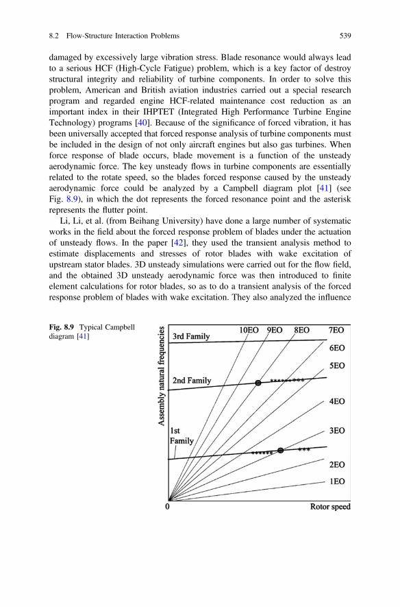
damaged by excessively large vibration stress. Blade resonance would always leadto a serious HCF (High-Cycle Fatigue) problem, which is a key factor of destroystructural integrity and reliability of turbine components. In order to solve thisproblem, American and British aviation industries carried out a special researchprogram and regarded engine HCF-related maintenance cost reduction as animportant index in their IHPTET (Integrated High Performance Turbine EngineTechnology) programs [40]. Because of the significance of forced vibration, it hasbeen universally accepted that forced response analysis of turbine components mustbe included in the design of not only aircraft engines but also gas turbines. Whenforce response of blade occurs, blade movement is a function of the unsteadyaerodynamic force. The key unsteady flows in turbine components are essentiallyrelated to the rotate speed, so the blades forced response caused by the unsteadyaerodynamic force could be analyzed by a Campbell diagram plot [41] (seeFig. 8.9), in which the dot represents the forced resonance point and the asteriskrepresents the flutter point.
Li, Li, et al. (from Beihang University) have done a large number of systematicworks in the field about the forced response problem of blades under the actuationof unsteady flows. In the paper [42], they used the transient analysis method toestimate displacements and stresses of rotor blades with wake excitation ofupstream stator blades. 3D unsteady simulations were carried out for the flow field,and the obtained 3D unsteady aerodynamic force was then introduced to finiteelement calculations for rotor blades, so as to do a transient analysis of the forcedresponse problem of blades with wake excitation. They also analyzed the influence
Fig. 8.9 Typical Campbelldiagram [41]
8.2 Flow-Structure Interaction Problems 539

of the anharmonic design of asymmetric stator blade distribution, and the resultsshowed that the excitation force on the rotor changed from single-frequencyhigh-amplitude excitation force in the case of uniform stator blade distribution tomulti-frequency-component low-amplitude excitation force, indicating that theanharmonic design of asymmetric stator blade distribution could effectivelydecrease the wake excitation force on rotor blades thus increase fatigue life [43].Gong et al. analyzed the changes of flow graphs before and after conjugation by theflow-structure interaction numerical simulation method [44, 45], and the resultsshow that, as for high-aspect-ratio blade passage flows, there were great differencesin overall flow field parameters with the conjugation taken into account or not,Meanwhile, flow in the passage would also be significantly influenced by bladedeformations, and that the flow field was more sensitive to structural deformationsin off-design conditions. Figure 8.10 compares the standard deviations ofblade-surface static pressure coefficients in a low-pressure turbine with designconditions between the two simulation models: flow-structure interaction model andnon-conjugate model. Although the difference of time averaged load and the loaddistribution on blades between the two simulation models was not large, theunsteady characteristic of the flow field in blade passage was quite different, inwhich the flow field unsteadiness obtained in the flow-structure interaction simu-lation is weakened significantly [44]. Thus it can be seen that the flow-structureinteraction analysis method not only has great importance on the studies of blade
flow-structure non-conjugate flow-structure interaction
non-conjugate
Pressure side Suction side
interaction
Fig. 8.10 Standard deviations of static pressure coefficients of turbine rotor blades [44]
540 8 Multidisciplinary Coupling Analysis and Design

vibration problem, but also can effectively improve the capability of capturing thereal unsteady flow field in turbines.
8.2.3 Blade Flutter
Another important problem of aerodynamic conjugation is the aeroelastic stabilityproblem, which is named the flutter problem. Although turbomachinery aeroelas-ticity problems have been studied for more than half a century, there are still nocompletely reliable methods that can accurately predict the flutter stability of bladesand other typical structures.
Experimental research is an important approach to solve the flutter problem andalso a necessary step of verifying numerical simulation results. Flutter experimentscan be carried out for both individual components and the whole machine.However, the whole machine experiment is more complex and difficult thancomponent experiment. Therefore, detailed, specific, and parameterized analysis offlutter phenomena have to be carried out on the basis of component experiments.However, because component experiments are performed in relatively ideal envi-ronments, in which not all flutter influencing factors can be considerable. Forexample, the influence of adjacent blade rows cannot be modeled in cascade flutterexperiments. Thus, compared to experimental research, numerical simulation canobtain more flow field data as well as blade stress and vibration data. With thedevelopment of numerical simulation methods, numerical simulation has becomemore and more important in blade flutter studies. Generally methods of numericalinvestigations on the flutter problem can be divided into classical and conjugatemethods. Classical methods ignore the conjugate relation between the fluid and thestructure and solve problems in the two domains separately, while conjugatemethods solve them with conjugation taken into account. Classical methods mainlyinclude actuator disk method, eigenvalue method, energy method, etc. Becausethese methods do not consider problems that need to be solved in a conjugatemanner, their requirement for computing capability is low. So, they were widelyapplied in the early stage of research. However, the accuracy of these methods inpredicting the flutter problem is relatively lacking, and thus their applicability islimited to a certain problem [46, 47]. Conjugate methods acknowledge interactionbetween the fluid and the structure, which is just the essential difference betweenconjugate methods and classical methods. Conjugate methods are consistent withthe fact, and require more non-linear factors to be considered in the analysis of thefluid and the structure. Thus, the researcher could not only predict the momentwhen the flow turn unstable and flutter occur, but also predict the limit cyclecharacteristics of the unstability. A large number of experimental results suggestthat turbine blade flutter usually occurs in the form of limit cycle vibration withdifferent amplitudes, so predicting the size of the amplitude is more important thanpredicting the occurrence of flutter. It is because that limit cycle movement with asmall amplitude may not seriously impact the operation of turbomachinery. It is
8.2 Flow-Structure Interaction Problems 541

more important for designers to predict and avoid high-amplitude vibration.Therefore, prediction results obtained by conjugate methods are always moremeaningful for engineering applications. However, the current conjugate methodsrequire high computing capability, and their accuracy still needs to be furtherenhanced.
Because of the importance of the flutter problem, researchers have studied themechanism of turbomachinery blade flutter stability, parametric flutter prediction,and flutter parameterization measures for a long time with great achievements.There are many factors influencing flutter stability in turbomachinery environment,so that studies on the flutter problem are generally carried out by taking a certaindesign parameter as the judgment criterion. Thus, rules of flutter stability with thisparameter can be obtained through a systematic study on the parameter. In thedesign of primary stage of gas turbine, parameters such as reduced frequency,vibration mode, inflow incidence, and Mach Number are commonly used toevaluate stability of the blade flutter. For example, inflow incidence angle haveinfluence on the load on blades and flow within blade rows by directly effecting thetriangle of velocities, hence finally affect flutter stability. Carta et al. studied cascadeflutter stability of a linear compressor and present an idea that the reduced fre-quency, at which flutter occurs, decreases with the increase of the incidence angleand is unrelated to rotating stall [48]. Increasing the incidence angle would result inthe decrease of flutter stability, in which flow separation at the leading edge ofblades will be the main factor influencing flutter stability when the incidence angleexceeds a critical value. Ellenberger et al. indicated that things will be differentwhen there are shock waves in flows. They studied torsional flutter in a compressorcascade and found that shock waves have a great influence on flutter stability thanseparation bubbles [49], which is not exactly the same in turbines. He et al. carriedout experimental investigations on unsteady flows with different incidence angles ina torsional vibration cascade of a low-pressure turbine of which the results showthat separation bubbles on the pressure surface would reduce flutter stability, whileflows after the reattachment point would increase flutter stability. On the whole, theincidence angle has little influence on flutter stability [50]. With the deepeningstudy of turbomachinery flutter problems, the important influence of vibration modeon flutter stability has been paid more attention. Bendiksen et al. studied oscillatingcascade flows at bending and torsional vibration in a series of flow conditions by theanalytic method, of which the results show that there is a big difference in flutterstability between bending vibration and torsional vibration [51]. Using the stabilityparameter diagram method, Panovsky et al. systematically studied the influence ofvibration modes in a 2D cascade on flutter stability [52, 53]. In this method, rigidmotion assumption is used and all the possible vibration modes are transformed intotorsional motions. The stability parameter diagram relating to torsional center andstability parameters of torsional motions could be obtained, which clearly indicatesthe flutter stability of all possible rigid motions. The results show that vibrationmodes have significant influence on flutter stability as well as the influence ofgeometrical parameters is also non-negligible. Yang, He, et al. studied the influenceof blade tip clearance in a compressor cascade on flutter stability, and the results
542 8 Multidisciplinary Coupling Analysis and Design

show that tip leakage flows can reduce flutter stability compared to the case withsealed tips [54].
As for numerical prediction of flutter stability, Wang (from Beihang University)has made a large number of fruitful studies [55–58] that a 3D turbomachineryaeroelasticity computing software based on the time-domain method has beendeveloped, which can be used to make forced response and flutter analysis. Wangalso systematically made analysis of several factors influencing aeroelastic stabilityof turbomachinery blades, in which a study on blades of a compressor reveals thatblade modal and inter blade phase angle have crucial influence on flutter of tur-bomachinery blades, and that shock waves on the suction surface and post-waveseparation zone are the important factors inducing blade flutter. With respect todetermination of flutter stability, Zhang et al. carried out flow-structure interactionnumerical simulation investigations on the flutter problem of fan and turbine bladesby taking the influence coefficient method into 3D unsteady numerical simulation.Based on the rigid motion assumption, modal superposition principle and the ideaof all rigid motions can be expressed as torsional rigid motions, then they estab-lished the stability parameter contour map that can describe all the possible rigidmotions and stability parameter relations as well as discussed the influence of thekey parameters on flutter stability [59–61]. Figure 8.11 shows the diagram ofrelations between the stability parameters of a turbine blade profile and the positionof rotation axis, in which the region with the stability parameter S\0 covers thetorsional center positons of all the unstable rotational modes of the turbine bladeprofile under the research conditions. It is shown that the most unstable region islocated in an oval area with the trailing edge of the reference blade as its center, anda “reverse-C” region at the leading edge vertex of the reference blade has thehighest stability parameter. In addition, the stability parameter is relatively largealong the extension direction of the trailing edge. As for low-pressure turbines, astability parameter contour map suggests that vibration mode has the greatest
Fig. 8.11 Relations betweentypical turbine stabilityparameters and position oftorsion shaft [59]
8.2 Flow-Structure Interaction Problems 543
influence on flutter stability. A tiny change of vibration mode would make a greatdifference on flutter stability. Reduced frequency, inlet flow angle, and MachNumber have relatively small influence on flutter stability, meanwhile, influence oftip clearance is the weakest among the discussed parameters. Stability parameterdistribution of the subsonic low-pressure turbine and the transonic fan rotor dis-cussed in the study show the same distribution trends, indicating that there is certainsimilarity in flutter stability between turbine blades and fan blades.
8.3 Aero-acoustic Conjugate Problems
8.3.1 Noise and Aero-acoustic Conjugate Problemsin Turbine
As great progress has been made in terms of aerodynamic characteristics, reliability,and maintainability of turbines, noise problem is getting more and more attention.In aviation, for example, aircraft noise may seriously influence residents near air-ports. With the development of the air transport industry, the aircraft noise pollutionproblem is further exacerbated across the world. Aero-engines are the main sourceof aircraft noise, hence all the western aviation powers have implemented specificresearch programs, aiming at the noise problem, such as AST of NASA and QAT inAmerica. These programs are mainly intended to significantly reduce aero-enginenoise and other pollutions so as to meet demand for intensive air transport [62]. Jetnoise is the main constituents of noises generated by aero-engines that were usedpreviously. However, with the bypass ratio of modern civil aero-engines increasing,jet noise was reduced greatly and large-size fans became another main source ofengine noises [63]. Therefore, a large number of studies on fan noise reduction havebeen carried out in aviation field since 1970s consequently fan noise was greatlyreduced as well. Thus, the turbine noise problem, which was “neglected” in pre-vious, became more and more obvious. For example, in the approaching andlanding process of aircrafts with their engines set at idling rating, the interactionbetween rotor and stator noise of low-pressure turbines has become one of the mainnoise sources of aero-engines. Therefore, more and more institutes and researchershave paid great attention to tahte how to reduce low-pressure turbine noise indesign. For example, the Sixth Framework Programme of the EU regards noisereduction technologies for low pressure turbines as an important research subject[64]. Figure 8.12 shows the sources of noises generated by a typical civil airplaneduring take-off and landing. It be seen that noise level of turbine exceeds jet noiseeven approaches fan noise level, becoming the second largest source of enginenoise [65]. Figure 8.13 shows the influence of noises generated by components onoverall noise of a typical modern aero-engine with a bypass ratio of 8 in the process
544 8 Multidisciplinary Coupling Analysis and Design

of landing. The results show that an increase of 10 dB in turbine component noisewould lead to an increase of about 2.5EPNdB (even up to 4EPNdB in some cases)in overall equivalent perceived noise of the engine [64].
Turbomachinery noise reduction methods can be generally divided into twokinds: (1) sound source control method which reduce noise generation from thesource by optimization design of turbomachinery. (2) propagation path controlmethods which reduce noise by installing devices (i.e. acoustic liners), whichhave sound absorption function or effect the propagation paths of noise. Bothof the above two kinds of methods have been explored effectively and havebeen successfully applied in the field of reduction of aero-engine fan noise.However, because working temperature of turbine components is very highand may beyond the temperature limit of acoustic treatment materials, appli-cation of acoustic liners in turbines is limited in particular. In this case,aerodynamic optimization design for turbines, which aimed at sound sourcesand acoustic problems, becomes one of the key point reducing turbine noise.Currently, research institutes have carried out a large number of studies onlow-pressure turbine noise reduction based on a large quantity of experimentaldata. Meanwhile, the empirical models for predicting turbine noise based on
Fig. 8.12 Sources of aircraft noises during take-off and landing [65]
Fig. 8.13 Influence of noisesgenerated by components onoverall noise of a typicalbypass ratio 8 aero-engine inlanding [64]
8.3 Aero-acoustic Conjugate Problems 545

aeroacoustics theories and a large quantity of experimental data for enginenoise have been developed. Also, correlations among noise have been estab-lished with turbine dimensions, rotation speed, flow rate, output work, tem-perature, and other parameters so as to evaluate the noise generated by turbine,which make it possible to consider turbine noise reduction at the initial stage ofaerodynamic and structural design for low-pressure turbines [66, 67]. Sun(from Beihang University) has done a lot of basic research of aeroacoustics andhas made fruitful achievements as well [68, 69] (see Fig. 8.14).
It’s worth noting that aerodynamic performance of low-pressure turbine iscrucial to the economic efficiency of the engine. Therefore, noise reduction andaerodynamic performance of low-pressure turbines should be considered together.In other words, influence of all the noise reduction measures on low pressureturbine aerodynamic performance must be taken into account, which needs to beconsidered in the process of aerodynamic design. Effective aero-acoustic conjugatedesign refers to the design method, in which the influence of turbine parameters onboth aerodynamic and acoustic performance is considered during the entire process
(a) Influence of loading coefficient (b) Influence of maximum outer diameter
(c) Influence of exit Mach number
Fig. 8.14 Influence of key parameters of a civil LP turbine on aerodynamic performance andnoise level [72]
546 8 Multidisciplinary Coupling Analysis and Design

of parameter selection and modeling, so as to achieve the improvement for bothaerodynamic performance and noise level from the source.
8.3.2 Noise Reduction in Low-Dimensional AerodynamicDesign
Presently, a well design system has been established for aerodynamic design oflow-pressure turbines. Therefore, it is an important aero-acoustic integrated designmethod that takes acoustic considerations and requirements into the present aero-dynamic design system. According to spatial complexity, aerodynamic design ofturbines can be divided into one-dimensional design, two-dimensional design, andthree-dimensional design, which is the general steps of turbine aerodynamic designand then aero-acoustic conjugate design could be performed in any one of thesethree steps. As mentioned above, aero-thermodynamic characteristics of flows canbe obtained more easily in low-dimensional (one dimension and two dimensions)aerodynamic design, so that one will get twofold results with half the effort. Thesame goes for acoustic problems.
Tyler and Sofrin modal the improvement method is the most important tool foranalyzing noise reduction in one-dimensional aerodynamic design. As introducedby this method, selecting appropriate numbers of guide vanes and rotor blades caneliminate the discrete noise generated by the interaction between rotor and stator ina certain frequency range, thus reducing the noise influence on the outside. Thisprinciple has been successfully applied in aero-engine fan design and has becomean important basis for determining number of fan blades [70]. Tyler and Sofrinindicated that, because of the limitation of the “pipeline” boundary conditions inturbomachines, noise generated by the interaction between unsteady inflows andblades can only exist in specific forms, named modes. The propagation mode ismainly determined by number of blades, rotating speed, and aerodynamic condi-tions (flow rate, temperature, etc.). As for a turbine stage consisting of B rotorblades and V stator blades, the circumferential modal number, m, of the soundmodes generated by blade interaction can be obtained by the Tyler and Sofrinequation:
m ¼ hB� sV ð8:1Þ
where, h is the number of blade passing frequency harmonic, s is an arbitraryinteger, representing the space harmonics generated by the stator. The blade-tipcircumferential Mach Number of the interfering rotating pressure modes in theabove model can be written:
8.3 Aero-acoustic Conjugate Problems 547

Ma;m ¼ hBxRmc
ð8:2Þ
where, x is the rotating speed, R is the blade tip radius, c is the sound velocity. Thecritical circumferential Mach Number can be obtained by the equation below:
M0a;m ¼ am;l
mð8:3Þ
where, am;l is the radial wave number, which depends on the inner and outerdiameter of the turbine. Tyler and Sofrin indicates that when Ma;m\M0
a;m, the soundwaves are eliminated and the amplitude would attenuate rapidly along the axialdirection, as well as when Ma;m [M0
a;m, the sound waves show the outgoingcharacteristics. By eliminating discrete noise, the above method serves as a simpleapproach for determining the number of turbine blades. It is seen that the selectionmethod of blade should conjugate with the design of turbine meridional channel[70]. A study has shown that the dominant sources of sound generated by turbineare the BPF (blade passing frequency) discrete noise rear turbine stage. Thus, theabove blade number determination method is generally used for low-pressure tur-bine in the last one or two stages [71].
Integrating aerodynamic performance and noise assessment models with eachother is of great significance for the design of low-pressure turbines inlow-dimensional model. Tan, Qiao, et al. (from Northwestern PolytechnicalUniversity) introduced the Lowson discrete noise prediction model to the turbineaerodynamic design procedures, analyzing the influence of key parameters of amulti-stage low-pressure turbine on noise characteristics in a civil airplane. Theresults show that last-stage work distribution of the turbine has significant influenceon aerodynamic noise. With the increase of last-stage work, noise level decreasesfirst and then increases, while the aerodynamic efficiency of turbine componentspresents an opposite trend. Therefore, it is possible to obtain an optimal range ofwork distribution, in which both the aerodynamic performance and noise perfor-mance of turbine components could be satisfactory. In addition, both componentefficiency and noise change monotonously with the outer diameter of the turbine.With the increase of outer diameter, both aerodynamic performance and noise levelof the turbine are improved, in which the noise reduction mainly results from thereduction of relative velocity in rotor blade tip. Exit Mach Number is anotherimportant parameter in the design of low-pressure turbines. The flow field in therotor of the last-stage turbine could be improved by growth of the exit Machnumber and thus the aerodynamic performance may be improved as well. However,increase of exit Mach Number would lead to the increase of relative velocity ofrotor blade tip, which is harmful to turbine noise control [72, 73].
548 8 Multidisciplinary Coupling Analysis and Design

8.3.3 Aero-acoustic Integrated Design Based on Fully3D-Modeling
Both discrete noise and broadband noise are mainly caused by unsteady flows inturbines at different scales of space and time. In order to reduce the noise from thesource, unsteady flows in turbines have to be organized effectively. All these worksare closely related to three-dimensional models of turbines.
MTU and DLR in Germany are the earliest institutions studying turbine noiseproblems, which carried out a series of numerical and experimental studies on ahigh-speed three-stage low-pressure turbine test rig, and found that the interactionbetween the low-pressure turbine discrete noise mode and EGVs (Exit Guide Vane)has great influence on discrete noise characteristics [74], as well as the interactionbetween EGVs and some discrete noise may generate non-cut-off modes, thusgoing against turbine noise control [75]. To solve this problem, they discussed themethod of reducing turbine noise by leaned EGVs (see Fig. 8.15) with the aim ofchanging the phase of the interaction between EGVs and upstream wakes as well asother unsteady flow structures by changing EGV, thus controlling the noise. Bothnumerical calculation and experimental results suggest that appropriate lean angletogether with optimized number of EGVs can significantly reduce the noise causedby interaction between the low-pressure turbine and EGVs [76].
In fact, leaning and other 3D modeling methods could be used not only forEGVs, but also for guide vanes in the rear stages of the turbine to reduce noise.Zhao, Qiao, et al. studied a high-aspect-ratio low-pressure turbine and the resultsshow that the reverse-lean guide vane design, in which the suction surface and thehub form an acute angle, can effectively reduce the noise of the turbine. However,this scheme may do harm to the aerodynamic performance of turbines. Thus, it isnecessary to explore the feasibility and methods of reasonable leaned vane design inorder to achieve improvement in both aerodynamic and noise performance [77, 78].Besides Secondary flows in turbines could not only result in broadband noise, butalso influence the interaction between rotor and stator in turbines, effecting thediscrete noise. By taking the influence of leakage flows as an example, studies haveshown that increased tip clearance would reduce the discrete noise caused by
Fig. 8.15 EGV layout schemes: conventional scheme (left), leaning scheme (right) [76]
8.3 Aero-acoustic Conjugate Problems 549

interaction between the turbine rotor and upstream vanes, which is mainly because thatthe height of the blades that interact with upstream wakes decreases. However, largerclearance would also enhance leakage flows and thus may increase the noise caused byinteraction between the leakage flows and downstream guide vanes [76]. Therefore,height of blade tip clearance needs to be considered in a multi-stage environment, evenif only the noise problem is take into consideration. Except rotor-stator interaction,clocking effects in multi-stage turbines are another important unsteady phenomenon,for which Blaszczak did an experimental study on the rotor-rotor and stator-statorclocking effects in a two-stage turbine, and suggest that clocking effects have significantinfluence on turbine noise, as well as reasonable use of clocking effects can effectivelydecrease turbines noise level [79]. Unfortunately, they observed opposite results indifferent experiments when exploring whether aerodynamic performance and noiselevel could be improved simultaneously. It is once again that confirms the complexityof the aero-acoustic conjugate problem, for which more systematic and comprehensivestudies are needed to obtain its mechanism.
8.4 Multidisciplinary Design Optimization Technologies
As previously mentioned, in the process of turbine design, not only the aerodynamicperformance should be taken into account, but also problems , including structure,strength, lifetime, heat transfer, noise, etc, should be considered. These problems aregenerally ascribed to the distribution of pressure, temperature, and other physicalparameters in the fluid domain and solid domain of a turbine, which are interactivelydistributed and lead to a multidisciplinary conjugate design problem essentially.Generally, the multidisciplinary conjugate problem in the design of turbine wouldmainly include structure/strength/vibration problems, heat transfer problems, aero-dynamic problems, noise problems, secondary air system, materials and processes,and so on. Although turbine design is a complicated systematic engineering withmultidisciplinary conjugation due to the limitations of technologies and tools, it hasalways been done by an iteration process of design, verification, and modification,which are carried out in each discipline independently. This design process not onlyis difficult to achieve the best optimizations of turbine performance in all directions,but also prolongs the lead time of turbine components.
With the more strict requirements for lead time of turbine and comprehensiveindexes (including performance, lifetime, reliability, cost of operating and manu-facture, etc.), researchers have begun to consider the interaction among differentsubjects and studied the MDO technologies applicable for turbine design based onthe previous study. MDO was first proposed by Sobieszczanski-Sobieski (lateracted as the chairman of the technical committee of AIAA-MDO, NASA), whichaims to fully study and understand the interaction between disciplines and sub-systems by using computer and numerical simulation technologies, as well asobtain the optimal solution for the entire system and shorten design cycle, thusmaking the developed products more competitive at last. Because the MDO
550 8 Multidisciplinary Coupling Analysis and Design

technology has an obvious advantage in handling multidisciplinary conjugateproblems, researchers have drawn universal attention from aviation industry andachieved great development in the recent 20 years. For example, NASA andLockheed MartinCorporation (US) used the MDO technology in cooperativedevelopment of a aerospike engine for the X-33 aircraft. GE, PW, and otheraero-engine companies also took the technology to their aero-engine design pro-cedures so as to improve the performance of aero-engine, decrease lead time, andreduce life-cycle cost.
8.4.1 General Description of MDO Problem
Decomposing a complex system into several subsystems by disciplines or com-ponents is an effective method for analyzing the complex system. According torelations among subsystems, complex systems can be divided into two kinds:hierarchic systems and non-hierarchic systems. As for hierarchic system, infor-mation flows among subsystems are sequential and there are no coupling relationsamong subsystems, which are organized in a pyramidal pattern, where the upperlayer makes requests to the lower layer and the lower layer retroaction its designresults to the upper layer, thus developing a tree-like structure on the whole.Subsystems in a non-hierarchic system are not hierarchically organized, whichmeans information between subsystems are conjugated together which means thatiterative computations is required for problems among subsystems and the systempresents a network structure in general, thus are also deemed as conjugate systems.Most complicated engineering systems in reality are non-hierarchic systems, inwhich the multidisciplinary conjugate problem in the design of gas turbine alsobelongs to the category of non-hierarchic systems.
The MDO problem mainly contains three basic elements including designvariable, constraint condition, and objective function. Design variables are a groupof mutually independent variables that are used to determine the system or designscheme, which should be determined in design and called independent variables ordesign parameters. If a system has n independent design variables ðx1; x2; . . .; xnÞ,then the design variables can be described with a vector or matrix:
X ¼ ½x1; x2; . . .; xn�T ð8:4Þ
where, X is a vector in an n-dimensional space, namely a design scheme, of whichprojectional components on n mutually orthogonal coordinate axes are a group ofdesign variables ðx1; x2; . . .; xnÞ of the design scheme, as well as the changes of thevector X in the n dimensional space is represent for the changes of these designvariables. Mathematically, the range of variation of the design variables is unlimitedin unconstrained optimization problems, however, in actual engineering problems,the exploration intervals (i.e. variable intervals) are typically set and given both the
8.4 Multidisciplinary Design Optimization Technologies 551

upper and lower limits according to the problems actual situation as well asdesigners experience, so as to reduce the workload and reduce design time. In theorthogonal coordinate system consisting of design variables, the multi-dimensionalexploration space formed by the upper and lower limits of the variable intervals iscalled a design space. If a problem contains n independent design variables, then itsdesign space is a n-dimensional Euclidean space, denoted by En or Rn. The region iscalled a feasible region which is made up of all the points (x1, x2, . . . , xn) meetingall constraint condition as well as the points X in the feasible region are calledfeasible design schemes or feasible solutions. In other words, a feasible designregion in a variable space is the region which is limited by constraint conditions,and is a part of the variable space. In general, the optimization process of MDO andfinally the optimal points should be only within the feasible region obtained.Otherwise, the obtained design parameters will lose their meaning since they do notmeet the constraint conditions (see Fig. 8.16).
Constraint conditions are limiting conditions in design, which are generallyfunctions of design variables and also called constraint functions. They are gen-erally divided into performance constraints and boundary constraints. Performanceconstraints refer to technical indexes that need to be met in design, such as flow rateand power of turbine. In addition, Boundary constraints include the permittedranges for the design, such as the size of turbine rotation speed, and weight as well.Constraint conditions can be typically divided into equality constraints andinequality constraints by their expression forms. The mathematical expressions ofthe two kinds of constraints can be written:
Fig. 8.16 Influence of EGVnumber and lean angle onturbine noise [76]
552 8 Multidisciplinary Coupling Analysis and Design

hiðXÞ ¼ 0; i ¼ 1; 2; . . .lgjðXÞ� 0; j ¼ 1; 2; . . .m
ð8:5Þ
where, l and m respectively represent the number of equality constraints andinequality constraints.
Objective function is also called target function, which is the criterion forassessing all the design schemes in the relevant space. In other words, objectivefunction is mathematical description of design objectives and tasks. Generally,objective function is a function of independent design variables,X ¼ ½x1; x2; . . .; xn�T , which is described as f ðXÞ:
f ðXÞ ¼ f ðx1; x2; . . .; xnÞ ð8:6Þ
In general, optimization problem is a process of obtaining the maximum orminimum value of the objective function.
For a design problem in which the variable space is En, the design variable isX ¼ ½x1; x2; . . .; xn�T and the objective function is f ðXÞ, as well as the equalityconstraint and inequality constraint are hiðXÞ ¼ 0 and gjðXÞ� 0 respectively, thenthe design problem can be expressed as:
min f ðXÞs:t: hiðXÞ ¼ 0; i ¼ 1; 2; . . .l
gjðXÞ� 0; j ¼ 1; 2; . . .mX 2 En
8>><
>>:
ð8:7Þ
8.4.2 Application of MDO Technology in Turbines
In design of turbine components, the most significant conjugate problems refer tothe conjugate problems in the solid domain, including the structural strength and theheat transfer problems, as well as the problems in the fluid domain includingaerodynamic and noise problem, as shown in Fig. 8.17. The conjugation betweenaerodynamic problem and other three problems respectively are discussed in thefirst three section of this chapter, but in fact, all the four problems are not inde-pendent. This is not only reflected in the above-discussed coupling mechanismbetween aerodynamic problem and the other three problems, but also because,technically, all physical problems are under the significant influence of factors inmany aspects. For example, the distribution of stress field, displacement field, andother physical quantities in the solid domain, which are the concerns of thestructural strength problem, is closely related to temperature field in the soliddomain and pressure field in the fluid domain. Meanwhile, fluctuation pressure fieldin the fluid domain, which is the concern of the noise problem, is related to the
8.4 Multidisciplinary Design Optimization Technologies 553

displacement field in the solid domain. Therefore, conjugate design optimizationmakes a great difference on the design of turbines.
Although there was no discussion and research on MDO for turbine componentsuntil 1990s, the MDO problem has got high attention from many research institutesand researchers, furthermore, considerable achievements have been made [81, 82].Yue et al. (from Northwestern Polytechnical University) carried out a detailed studyon MDO methods for turbine blades in an aero-engine. Figure 8.18 shows theprocedures of fully 3D multidisciplinary feasible optimization design of turbineblades, which were established by them. By using modeling parameters of eachsection of the turbine blades as system design variables of the MDO, as well asusing aerodynamic performance, natural vibration frequency, and blade equivalentstress of the turbine blades as optimization objectives and constraint conditions, thisoptimization system, in each optimization cycle, first conducts a multidisciplinary(aerodynamics, heat transfer, and structure) conjugate analysis and then carries outanalysis and inspection from three disciplines including fatigue, vibration, andreliability.
A major factor limiting the wide application of the multidisciplinarytightly-coupled design optimization method is the huge computational cost in theprocess of repeated iterative optimization, which is enormous even if the globalapproximation equation for the tightly-coupled analysis is established by using testdesign method. The time consumption of single-discipline analysis of these samplepoints is acceptable, but the huge amount of test design points would make the timecost of the tightly-coupled analysis unacceptable. In order to improve both theprecision of the multidisciplinary optimization design of turbine blades and theoptimization efficiency so as to enhance the realizability of the multidisciplinary
Fig. 8.17 Major multidisciplinary conjugate problems involved in turbine design
554 8 Multidisciplinary Coupling Analysis and Design

optimization design, Wang et al. established a set of multiple-precision analysisbased multidisciplinary design optimization methods by introducing the VCM(Variable complexity modeling) method as well as combining the CO(Collaborative Optimization) strategy [83]. Figure 8.19 shows the multiple-precision analysis based CO strategy which is used in the multidisciplinary opti-mization design of turbine blades. The optimization strategy is designed to take themultiple-precision analysis model into the CO strategy by means of variablecomplexity modeling. Two subdiscipline-level optimizers, which are respectivelyused to deal with structural strength optimization and aerodynamic optimization,are connected to the system-level optimizer, of which their operation modes are
Fig. 8.18 Typical multidisciplinary design optimization procedures for turbine blades [80]
Fig. 8.19 Multiple-precision MDO analysis based CO strategy [83]
8.4 Multidisciplinary Design Optimization Technologies 555
same as that of the CO strategy. The most important characteristic of this opti-mization strategy is the nesting of a CO cycle in the major cycle. Aerodynamicanalysis, flow-structure loosely-coupled analysis, and flow-structure tightly-coupledanalysis would be performed simultaneously for the optimal values obtainedthrough CO, in which the former two kinds of analysis are medium-precisionanalysis, while the last analysis is high-precision analysis. Response data of the lastanalysis serves as scaling functions for the former two kinds of analysis. Results ofan application of the multidisciplinary optimization method in blade design of aturbine show that, only 9 iterations of high-precision analysis were needed to ensurethe precision of the optimized results by the optimization algorithm.
MDO methods are not yet perfect and there are some issues in practical engi-neering applications of the methods, but they have great advantages in improvingdesign efficiency and success rate. With the development of research and computingtechnologies, MDO methods may become an integral part of advanced turbinedesign system in the near future.
References
1. Li, X. (2006). Mordern gas turbine technology. Beijing: Aviation Industry Press.2. Han, J. C., Duffa, S., & Ekkad, S. V. (2000). Gas turbine heat transfer and cooling
technology. New York: Taylor & Francis.3. Cao, Y., Tao, Z., & Xu, G. (2005). Heat transfer in aero-engine. Beijing: Beihang University
Press.4. Dixon, J. A., Valencia, A. G., Coren, D., et al. (2014). Main annulus gas path interactions—
Turbine stator well heat transfer. Journal of Turbomachinery, 136, 21010.5. Janke, E., & Wolf, T. (2010). Aerothermal research for turbine components: an overview of
the European AITEB-2 project. ASME Paper GT2010-23511.6. Han, J. C., & Rallabandi, A. (2010). Turbine blade film cooling using PSP technique.
Frontiers in Heat and Mass Transfer, 1, 013001.7. Monico, R. D., & Chew, J. W. (1993). Modelling thermal behaviour of turbomachinery discs
and casings. AGARD, Heat Transfer and Cooling in Gas Turbines.8. Dunn, M. G., Kim, J., Civinskas, K. C., et al. (1994). Time-averaged heat transfer and
pressure measurements and comparison with prediction for a two-stage turbine. Journal ofTurbomachinery, 116(1), 14–22.
9. Ameri, A. A., & Bunker, R. S. (2000). Heat transfer and flow on the first-stage blade tip of apower generation gas turbine: Part 2—Simulation results. Journal of Turbomachinery, 122(2),272–277.
10. Saha, A. K., Acharya, S., Bunker, R., et al. (2006). Blade tip leakage flow and heat transferwith pressure-side winglet. International Journal of Rotating Machinery.
11. Roy, R. P., Xu, G., & Feng, J. (2001). A study of convective heat transfer in a model rotor–stator disk cavity. Journal of Turbomachinery, 123(3), 621–632.
12. Pasinato, H. D., Squires, K. D., & Roy, R. P. (2004). Measurements and modeling of the flowand heat transfer in a contoured vane-endwall passage. International Journal of Heat andMass Transfer, 47(26), 5685–5702.
13. Simone, S., Montomoli, F., Martelli, F., et al. (2012). Analysis on the effect of a nonuniforminlet profile on heat transfer and fluid flow in turbine stages. Journal of Turbomachinery, 134,11012.
556 8 Multidisciplinary Coupling Analysis and Design

14. Dunn, M. G. (2001). Convective heat transfer and aerodynamics in axial flow turbines.Journal of Turbomachinery, 123(4), 637–686.
15. Rigby, D. L., & Lepicovsky, J. (2001). Conjugate heat transfer analysis of internally cooledconfigurations. ASME Paper GT2001-0405.
16. Huang, H. (2002). Numerical and experimental investigation on flow and heat fields inturbine cascade. Beijing: Chinese Academy of Sciences.
17. Bohn, D., Becker, V., Kusterer, K., et al. (1999). 3-D internal flow and conjugate calculationsof a convective cooled turbine blade with serpentine-shaped and ribbed channels. ASMEPaper 99-GT-220.
18. Li, Y. (2011). A 3-D conjugate heat transfer solver and methodology research. Beijing:Beihang University.
19. Wang, P., Li, Y., Zou, Z. P., et al. (2012). Improvement of turbulence model for conjugateheat transfer simulation. Numerical Heat Transfer (Part A), 62(8), 624–638.
20. Li, H., Feng, G., Wang, S., et al. (2003). Numerical simulation method ofaerodynamics-themodynamics coupling in 3-D turbine cascade. Beijing: Journal ofEngineering Thermophysics, 24(5), 770–772.
21. Zhang, H. (2013). Investigation of numerical conjugate heat transfer method and couplingmechanism for hybrid porous/fluid/solid domains. Beijing: Beihang University.
22. Zhang, H., Zou, Z., Li, Y., & Ye, J. (2011). Preconditioned density-based algorithm forconjugate porous/fluid/solid domains. Numerical Heat Transfer (Part A), 60(2), 129–153.
23. Baoguo, Wang, Ge, Gao, Weiguang, Huang, et al. (2014). Unsteady Aerodynamics. Beijing:Beijing Institute of Technology Press.
24. Lucor, D., Xiu, D., & Su, C. H. (2003). Predictability and uncertainty in CFD. InternationalJournal for Numerical Methods in Fluids, 43(5), 483–505.
25. Lehmann, K., Thomas, R., Hodson, H., et al. (2009). Heat transfer and aerodynamics ofover-shroud leakage flows in a high-pressure turbine. ASME Paper GT2009-59531.
26. Chen, W., Kan, R., & Ren, J. (2010). Experimental investigation of heat transfer and pressuredrop in a two-pass internal coolant passages of gas turbine airfoil. Beijng: Journal ofAerospace Power, 12, 2779–2786.
27. Arroyo, O. C., Gunnar, J. T., & Wallin, F. (2012). Experimental heat transfer investigation ofan aggressive intermediate turbine duct. Journal of Turbomachinery, 134, 51026.
28. Serkan, Ö. (2004). Effect of heat transfer on stability and transition characteristics ofboundary-layers. International Journal of Heat and Mass Transfer, 47(22), 4697–4712.
29. Wu, X., & Moin, P. (2010). Transitional and turbulent boundary layer with heat transfer.Physics of Fluids, 22(8), 1–8.
30. Shafi, H. S., Antonia, R. A., & Krogstad, P. A. (1997). Heat flux measurements in a turbulentboundary layer on a rough wall. International Journal of Heat and Mass Transfer, 40(12),2989–2993.
31. Krogstad, P. A., Antonia, R. A., & Browne, L. W. B. (1992). Comparison between rough andsmooth-wall turbulent boundary layers. Journal of Fluid Mechanics, 245, 599–617.
32. Han, J. C. (2013). Fundamental gas turbine heat transfer. Journal of Thermal Science andEngineering Applications, 5(2), 21007.
33. Giel, P. W., Fossen, G. J., Boyle, R. J., et al. (1999). Blade heat transfer measurements andpredictions in a transonic turbine cascade. ASME Paper 99-GT-125.
34. Garg, V. K. (2002). Heat transfer research on gas turbine airfoils at NASA GRC.International Journal of Heat and Fluid Flow, 23(2), 109–136.
35. Mischo, B., Burdet, A., & Abhari, R. S. (2011). Influence of stator-rotor interaction on theaerothermal performance of recess blade tips. Journal of Turbomachinery, 133, 11023.
36. Maffulli, R., & He, L. (2013). Wall temperature effects on heat transfer coefficient. ASMEPaper GT2013-94291.
37. Xing, J., Zhou, Sh., Cui, E. (1997). A survey on the fluid-solid interaction mechanics. Beijing:Advances in Mechanics, 27(1):19–30.
38. Sheng, Zhou, et al. (1989). Turbomachinery aeroelasticity introduction. Beijing: NationalDefense Industry Press.
References 557
39. Wilson, M. J., Imregun, M., & Sayma, A. I. (2006). The effect of stagger variability in gasturbine fan assemblies. ASME Paper GT2006-90434.
40. Fang, Ch. (2004). Prospective development of aeroengines. Shenyang: Aeroengines, 30(1),1–5.
41. Marshall, J. G., & Imregun, M. (1996). A review of aeroelasticity methods with emphasis onturbomachinery applications. Journal of Fluids and Structures, 10(3), 237–267.
42. Meng, Y., Li, L., Li, Q. (2006). Transient analytical method of vane forcing response understator-rotor wake influence. Beijing: Journal of Beijing University of Aeronautics andAstronautics, 32(6):671–674.
43. Meng, Y., Li, L., Li, Q. (2007). Investigation of force under asymmetry stator wake. Beijing:Journal of Beijing University of Aeronautics and Astronautics, 33(9):1005–1008.
44. Gong, S. (2008). Research on unsteady flow and blade forced response in turbomachinery.Beijing: Beihang University.
45. Gong, S., Zou, Z., Yang, Zh., et al. (2009). Numerical simulation of fluid-solid coupling ofblades in the last stage of a steam turbine. Beijing: Journal of Engineering for ThermalEnergy and Power, 24(1):31–36.
46. Whitehead, D. S. (1959). The vibration of cascade blades treated by actuator disk methods.Proceedings of the Institution of Mechanical Engineers, 173(1), 555–574.
47. Carta, F. O. (1967). Coupled blade-disc-shroud flutter instabilities in turbojet engine rotors.ASME Journal of Engineering for Power, 89(3), 419–426.
48. Carta, F. O., & St.Hilaire, A. O. (1980). Effect of interblade phase angle and incidence angleon cascade pitching stability. ASME Journal of Engineering for Gas Turbines and Power, 102(2), 391–396.
49. Ellenberger, K., Gallus, H. E. (1999). Experimental investigations of stall flutter in atransonic cascade. ASME Paper 99-GT-409.
50. He, L. (1996). Unsteady flow in oscillating turbine cascade; Part 1: Linear cascadeexperiment. ASME Paper 96-GT-374.
51. Bendiksen, O. O., & Friedmann, P. P. (1982). The effect of bending-torsion coupling on fanand compressor blade flutter. ASME Journal of Engineering for Power, 104(3), 617–623.
52. Nowinski, M., & Panovsky, J. (2000). Flutter mechanisms in low pressure turbine blades.ASME Journal of Engineering for Gas Turbines and Power, 122(1), 82–88.
53. Tchernycheva, O., Fransson, T. H., Kielb, R. E., et al. (2001). Comparative analysis of blademode shape influence on flutter of two-dimensional turbine blades. ISABE PaperISABE-2001-1243.
54. Yang, H., He, L., Wang, Y. (2008). Experimental Study on Aeroelasticity in LinearOscillating Compressor Cascade. PartII: Tip-clearance Effect. Beijing: Acta Aeronautica etAstronautica Sinca, 29(4):804–810.
55. Wang, Y. (1999). Researches on several problems of blade flutter in turbomachinery. Beijing:Beihang University.
56. Zhang, X., & Wang, Y. (2010). Influence of interblade phase angle on the flutter of rotorblades. Beijing: Journal of Aerospace Power, 25(02), 412–416.
57. Xu, K., & Wang, Y. (2011). Application of time domain method in aeroelastic computationsfor compressor rotors. Beijing: Journal of Aerospace Power, 26(01), 191–198.
58. Zhang, X., Wang, Y., & Xu, K. (2011). Effects of parameters on blade flutter inturbomachinery. Beijing: Journal of Aerospace Power, 26(07), 1557–1562.
59. Zhang, Z. (2009). Numerical simulation of flutter in turbomachinery. Beijing: BeihangUniversity.
60. Zhang, Z., Zou, Z., Wang, Y., et al. (2010). Flutter prediction method applied inturbomachinery design. Beijing: Journal of Propulsion Technology., 31(2), 174–180.
61. Zhang, Z., Zou, Z., Wang, Y., et al. (2010). Investigation of flutter prediction method fortransonic fan. Beijing: Journal of Aerospace Power, 25(3), 537–548.
558 8 Multidisciplinary Coupling Analysis and Design

62. Huff, D. (2004). Technologies for turbofan noise reduction. NASA Glenn Research Center.Cleveland, Ohio, 10th AIAA/CEAS Aeroacoustics Conference Manchester, United Kingdom,2004.
63. Qiao, W. (2010). Aeroengine aeroacoustics. Beijing: Beihang University Press.64. Nesbitt, E. (2011). Towards a quieter low pressure turbine: Design characteristics and
prediction needs. International Journal of Aeroacoustics, 10(1), 1–16.65. Batard, H. (2005). Development of the quiet aircraft—Industrial needs in terms of aircraft
noise and main achievements in Europe. Forum Acusticum 2005 International Conference,Budapest, Hungary.
66. Mathews, D. C., Nagel, R. T., & Kester, J. D. (1975). Review of theory and methods forturbine noise prediction. AIAA Paper 75-540.
67. Lavin, S. P., Ho, P. Y., & Chamberlin, R. (1984). Measurements and predictions of energyefficient engine noise. AIAA Paper 84-2284.
68. Sun, X., & Zhou, S. (1994). Aeroacoustics. Beijing: National Defense Industry Press.69. Dai, X., Jing, X., & Sun, X. (2011). Nonlinear acoustic dissipation mechanism of a slit
resonator. Beijing: Journal of Aerospace Power, 26(3), 530–536.70. Tyler, J. M. &, Sofrin, T. G. (1962). Axial flow compressor noise studies. SAE Technical
Paper 620532.71. Enghardt, L., Moreau, A., Tapken, U., et al. (2009). Radial mode decomposition in the outlet
of a LP turbine-estimation of the relative importance of broadband noise. AIAA Paper2009-3286.
72. Lowson, M. V. (1970). Theoretical analysis of compressor noise. Journal of the AcousticalSociety of America, 47(1), 371–385.
73. Tan, H., Qiao, W., Zhao, L., et al. (2012). Aerodynamics/acoustics integration design methodof low pressure turbine-overall parameters optimization. Beijing: Journal of PropulsionTechnology., 33(4), 573–578.
74. Enghardt, L., Tapken, U., Neise, W., et al. (2001). Turbine blade/vane interaction noise:Acoustic mode analysis using in-duct sensor rakes. AIAA Paper 2001-2153.
75. Broszat, D., Korte, D., Tapken, U., et al. (2009). Validation of turbine noise prediction toolswith acoustic rig measurements. AIAA Paper 2009-3283.
76. Broszat, D., Kennepohl, F., Tapken, U., et al. (2010). Validation of an acoustically 3Ddesigned turbine exit guide vane. AIAA Paper 2010-3806.
77. Zhao, L., Qiao, W., Tan, H. (2013). Aerodynamic-acoustic Three-dimensional NumericalOptimization of Low Pressure Turbine: Lean Vane Strategy. Beijing: Acta Aeronautica etAstronautica Sinca, 34(2): 246–254.
78. Zhao, L. (2012). Theory and method investigation of the aerodynamic-acoustics integrationdesign in turbine. Xi’an: Northwestern Polytechnical University.
79. Blaszczak, J. R. (2008). Performance improvement and noise reduction through vane andblade indexing of a two-stage turbine. AIAA Paper 2008–2941.
80. Yue, Z., Li, L., Yu, K., et al. (2007). Multidisciplinary design optimization of aeroengineturbine blades. Beijing: Science Press.
81. Talya, S. S., Chattopadhyay, A., & Rajadas, J. N. (2000). Multidisciplinary analysis anddesign optimization procedure for cooled gas turbine blades. AIAA Paper 2000-4877.
82. Chi, Z., Ren, J., & Jiang, H. (2013). Coupled aerothermodynamics optimization for thecooling system of a turbine vane. Journal of Turbomachinery, 136, 051008.
83. Wang, R., Jia, Z., Hu, D., et al. (2013). Multiple precision MDO strategy for turbine blade.Beijing: Journal of Aerospace Power, 28(5), 961–970.
References 559