chapter 7 – juan diaz wwtp unit process - minsa.gob.pa · chapter 7 – juan diaz wwtp unit...
TRANSCRIPT
Chapter 7 – Juan Diaz WWTP Unit Process
7.1 General The process of wastewater treatment can be categorized as consisting of the following elements:
Pretreatment Units
Biological Treatment
Final Clarification
Disinfection
Effluent Disposal
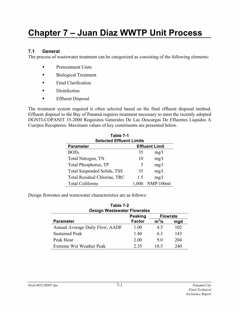
The treatment system required is often selected based on the final effluent disposal method. Effluent disposal to the Bay of Panamá requires treatment necessary to meet the recently adopted DGNTI-COPANIT 35-2000 Requisitos Generales De Las Descargas De Efluentes Liquidos A Cuerpos Receptores. Maximum values of key constituents are presented below.
Table 7-1 Selected Effluent Limits
Parameter Effluent Limit BOD5 35 mg/l Total Nitrogen, TN 10 mg/l Total Phosphorus, TP 5 mg/l Total Suspended Solids, TSS 35 mg/l Total Residual Chlorine, TRC 1.5 mg/l Total Coliforms 1,000 NMP/100ml
Design flowrates and wastewater characteristics are as follows:
Table 7-2 Design Wastewater Flowrates
Flowrate Parameter
Peaking Factor m3/s mgd
Annual Average Daily Flow, AADF 1.00 4.5 102 Sustained Peak 1.40 6.3 143 Peak Hour 2.00 9.0 204 Extreme Wet Weather Peak 2.35 10.5 240
Hwd:40521R807.doc 7-1 Panamá City Final Technical Assistance Report

7.0 Juan Diaz WWTP Unit Process
Table 7-3 Design Wastewater Characteristics (mg/liter)
Wastewater Constituent
Annual Average
Maximum Month
Maximum Week
Maximum Day
CBOD5 155 170 187 204 COD 400 440 490 530 TSS 155 170 187 204 NH3-N 17 18 20 22 TKN 22 24 26 29 TP 9 10 11 12
The annual average daily flow is the flow rate that the treatment plant will experience each year on average. Daily flow patterns to the treatment plant vary hourly following diurnal flow patterns. During this diurnal flow pattern, peak hour flows are expected to occur both during dry and wet weather conditions. For the large collection system serving the population of Panamá City, both the sustained hydraulic peaks and peak hour flows will occur. For the purposes of this report, a sustained peak is defined as a peak flow experienced daily for a period of three hours of more. A peak flow lasting three hours exceeds the hydraulic retention time of the aeration basins and is sufficient to stress the biological systems and impact plant effluent. Therefore, the biological process tankage must be designed to accommodate such hydraulic peaks without biological upsets.
A maximum hour peak flowrate is a peak flowrate experienced by the plant for a duration of no more than one hour at any given time. While such a peak will place stress on the biological systems of the treatment plant, the short duration of the peak flow will be accommodated by properly sized treatment basins.
Due to the magnitude of seasonal rainfall in Panamá City, an extreme wet weather peak is also anticipated. While such peak events will be experienced by the plant on a hydraulic basis, such events will not carry waste loadings of equal magnitude. Therefore, it would not be economical to hydraulically size biological treatment units for such an event. During extreme wet weather peak events most flows above that of the peak hour will bypass the biological treatment processes. They will be recombined with the treated effluent prior to chlorination. The Panamanian Government over the next 15 years will either implement an extensive Inflow / Infiltration program to reduce wet weather flows or construct additional treatment works.
The major unit processes of the proposed treatment facility have been sized to treat the peak hour flow rate with the largest unit out of service.
7.2 Pretreatment Units 7.2.1 Barscreens The screening operation is one of the key unit processes which can affect the performance/maintenance of downstream facilities. Rags, plastics and other debris can easily pass through the large opening (3/4-inch to 1-inch) of coarse mechanical bar screens traditionally Hwd:40521R807.doc 7-2 Panamá City Final Technical Assistance Report
7.0 Juan Diaz WWTP Unit Process
Hwd:40521R807.doc 7-3 Panamá City Final Technical Assistance Report
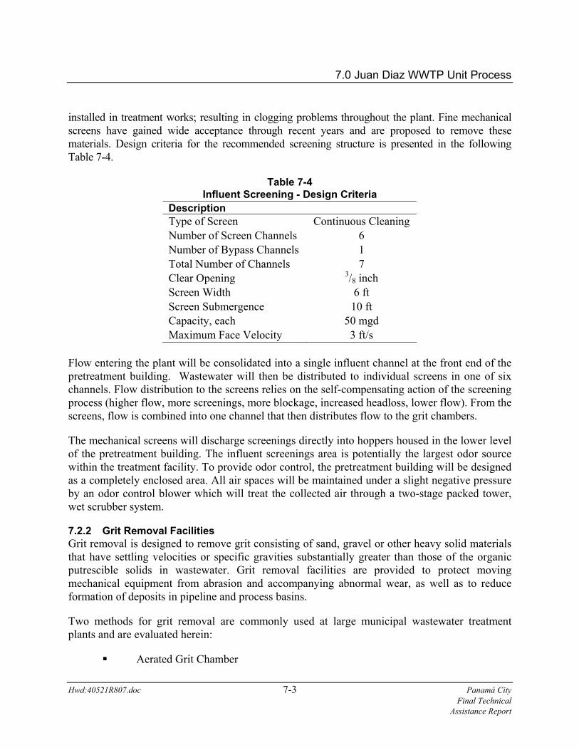
installed in treatment works; resulting in clogging problems throughout the plant. Fine mechanical screens have gained wide acceptance through recent years and are proposed to remove these materials. Design criteria for the recommended screening structure is presented in the following Table 7-4.
Table 7-4 Influent Screening - Design Criteria
Description Type of Screen Continuous Cleaning Number of Screen Channels 6 Number of Bypass Channels 1 Total Number of Channels 7 Clear Opening 3/8 inch Screen Width 6 ft Screen Submergence 10 ft Capacity, each 50 mgd Maximum Face Velocity 3 ft/s
Flow entering the plant will be consolidated into a single influent channel at the front end of the pretreatment building. Wastewater will then be distributed to individual screens in one of six channels. Flow distribution to the screens relies on the self-compensating action of the screening process (higher flow, more screenings, more blockage, increased headloss, lower flow). From the screens, flow is combined into one channel that then distributes flow to the grit chambers.
The mechanical screens will discharge screenings directly into hoppers housed in the lower level of the pretreatment building. The influent screenings area is potentially the largest odor source within the treatment facility. To provide odor control, the pretreatment building will be designed as a completely enclosed area. All air spaces will be maintained under a slight negative pressure by an odor control blower which will treat the collected air through a two-stage packed tower, wet scrubber system.
7.2.2 Grit Removal Facilities Grit removal is designed to remove grit consisting of sand, gravel or other heavy solid materials that have settling velocities or specific gravities substantially greater than those of the organic putrescible solids in wastewater. Grit removal facilities are provided to protect moving mechanical equipment from abrasion and accompanying abnormal wear, as well as to reduce formation of deposits in pipeline and process basins.
Two methods for grit removal are commonly used at large municipal wastewater treatment plants and are evaluated herein:
Aerated Grit Chamber
7.0 Juan Diaz WWTP Unit Process
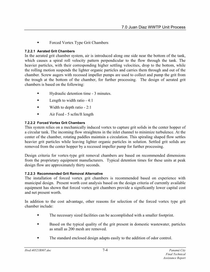
Forced Vortex Type Grit Chambers
7.2.2.1 Aerated Grit Chambers In the aerated grit chamber system, air is introduced along one side near the bottom of the tank, which causes a spiral roll velocity pattern perpendicular to the flow through the tank. The heavier particles, with their corresponding higher settling velocities, drop to the bottom, while the rolling motion suspends the lighter organic particles and carries them through and out of the chamber. Screw augers with recessed impeller pumps are used to collect and pump the grit from the trough at the bottom of the chamber, for further processing. The design of aerated grit chambers is based on the following:
Hydraulic detention time - 3 minutes.
Length to width ratio - 4:1
Width to depth ratio - 2:1
Air Feed - 5 scfm/ft length
7.2.2.2 Forced Vortex Grit Chambers This system relies on a mechanically induced vortex to capture grit solids in the center hopper of a circular tank. The incoming flow straightens in the inlet channel to minimize turbulence. At the center of the chamber, rotating paddles maintain a circulation. This spiraling shaped flow settles heavier grit particles while leaving lighter organic particles in solution. Settled grit solids are removed from the center hopper by a recessed impeller pump for further processing.
Design criteria for vortex-type grit removal chambers are based on recommended dimensions from the proprietary equipment manufacturers. Typical detention times for these units at peak design flow are approximately thirty seconds.
7.2.2.3 Recommended Grit Removal Alternative The installation of forced vortex grit chambers is recommended based on experience with municipal design. Present worth cost analysis based on the design criteria of currently available equipment has shown that forced vortex grit chambers provide a significantly lower capital cost and net present worth.
In addition to the cost advantage, other reasons for selection of the forced vortex type grit chamber include:
The necessary sized facilities can be accomplished with a smaller footprint.
Based on the typical quality of the grit present in domestic wastewater, particles as small as 200 mesh are removed.
The standard enclosed design adapts easily to the addition of odor control.
Hwd:40521R807.doc 7-4 Panamá City Final Technical Assistance Report

7.0 Juan Diaz WWTP Unit Process
Hwd:40521R807.doc 7-5 Panamá City Final Technical Assistance Report
The proposed design criteria for the forced vortex type grit chambers is presented below. These units can handle peak hour flows.
Table 7-5 Forced Vortex Grit Chamber - Design Criteria
Description Unit Type of Unit -- Forced Vortex No. of Units -- 4 Capacity, each mgd 70 HP / Unit HP 2
7.2.3 Grit Handling In addition to the grit chambers, the grit handling system consists of the collection and pumping of collected grit to separation with grit cyclones, grit classifiers and ultimate disposal into waiting containers in the pretreatment building hopper room. Cyclone degritters separate grit by use of centrifugal force. These units provide the highest grit removal efficiencies and have minimal space requirements. Solids from each grit chamber will be pumped to a cyclone, which will remove up to ninety-five percent of all grit particles having a mesh size of 100 or larger. Recessed impeller type pumps are recommended to reduce impeller wear. Fine grit (smaller than 100 mesh), which typically comprises about twenty percent of the incoming grit load, is extremely difficult to remove, generally less abrasive, and should not significantly impact downstream processes since it typically binds with the waste solids stream. Separated grit will flow into a grit washer that will discharge washed grit into dumpsters. The grit storage dumpsters will be located with the screening dumpsters inside the hopper room of the pretreatment building.
7.3 Biological Liquid Treatment The biological treatment process cultivates large populations of bacteria and other microorganisms commonly found in the aquatic environment. The microorganisms utilize the colloidal and soluble organic material found in wastewater as a source of food and energy. The dissolved organic material is thus converted to a form which can be readily separated from the liquid phase by sedimentation. The following discussion focuses on the analyses performed to determine the treatment process selection for the proposed facility.
7.3.1 Suspended Growth Biological Treatment The basic suspended growth reactor system consists of a number of interrelated components:
Basins sized to provide minimum hydraulic retention times and maximum organic loading levels based on accepted standards.
Oxygen source and equipment to disperse oxygen into the aeration basin at a rate sufficient to maintain an aerobic system.

7.0 Juan Diaz WWTP Unit Process
A means of mixing the basin contents to maintain suspension.
A clarifier to separate the suspended biological mass from the treated wastewater.
A method for collecting settled sludge in the clarifier for either returning to the aeration basin or wasting to the sludge treatment facilities.
Various types of suspended growth systems are available for the treatment of municipal wastewater. Among the most commonly used biological processes are:
Conventional Activated Sludge
Pure Oxygen Activated Sludge
Conventional Activated Sludge uses ambient air to provide the oxygen necessary for metabolic activity. As the name implies, Pure Oxygen Activated Sludge uses pure oxygen to sustain the biological activity. The primary advantage to using pure oxygen is the increased transfer efficiency, which allows for an aeration basin volume approximately one-half of that necessary for Conventional Activated Sludge. However, the Pure Oxygen Activated Sludge process requires the use of a sophisticated oxygen generation system. A cryogenic air separation plant would normally be used for a plant the size of that proposed for the Juan Diaz site. Pure Oxygen Activated Sludge is typically not cost effective unless land values are at a premium. Since this is not the case for the Juan Diaz site, this option will not be considered further.
7.3.1.1 Conventional Activated Sludge The term conventional activated sludge has typically applied to a plug flow system with various process modifications available including step-feed and tapered aeration. Single stage system variations differ only in the range of organic loading and the introduction points of air and wastewater.
Aeration basins are sized according to organic loading. Typical loadings are 20 to 40 lbs BOD/1,000 ft3 for conventional activated sludge systems and 40 to 60 lbs/1,000 ft3 for step feed activated sludge systems. Based on this standard, the range of aeration sizing is as follows:
(102 mgd) (8.34) (155 mg/l BOD) = 131,855 lbs BOD/day
@ 40 lbs BOD/1,000 ft3 = 3,296,375 ft3 required (24.6 MG)
@ 60 lbs BOD/1,000 ft3 = 2,197,583 ft3 required (16.4 MG)
The recommended depth for aeration tanks is twenty feet. Four basins are proposed for the Juan Diaz plant with each basin split into two sub-basins to offer better reliability should a basin be taken out of service for maintenance.
Hwd:40521R807.doc 7-6 Panamá City Final Technical Assistance Report
7.0 Juan Diaz WWTP Unit Process
Hwd:40521R807.doc 7-7 Panamá City Final Technical Assistance Report
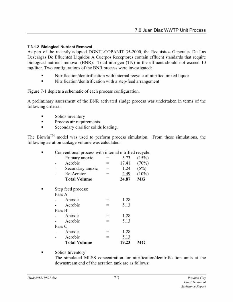
7.3.1.2 Biological Nutrient Removal As part of the recently adopted DGNTI-COPANIT 35-2000, the Requisitos Generales De Las Descargas De Efluentes Liquidos A Cuerpos Receptores contain effluent standards that require biological nutrient removal (BNR). Total nitrogen (TN) in the effluent should not exceed 10 mg/liter. Two configurations of the BNR process were investigated:
Nitrification/denitrification with internal recycle of nitrified mixed liquor Nitrification/denitrification with a step-feed arrangement
Figure 7-1 depicts a schematic of each process configuration.
A preliminary assessment of the BNR activated sludge process was undertaken in terms of the following criteria:
Solids inventory Process air requirements Secondary clarifier solids loading.
The BiowinTM model was used to perform process simulation. From these simulations, the following aeration tankage volume was calculated:
Conventional process with internal nitrified recycle: - Primary anoxic = 3.73 (15%) - Aerobic = 17.41 (70%) - Secondary anoxic = 1.24 (5%) - Re-Aerator = 2.49 (10%) Total Volume 24.87 MG
Step feed process: Pass A - Anoxic = 1.28 - Aerobic = 5.13 Pass B - Anoxic = 1.28 - Aerobic = 5.13 Pass C - Anoxic = 1.28 - Aerobic = 5.13 Total Volume 19.23 MG
Solids Inventory The simulated MLSS concentration for nitrification/denitrification units at the downstream end of the aeration tank are as follows:
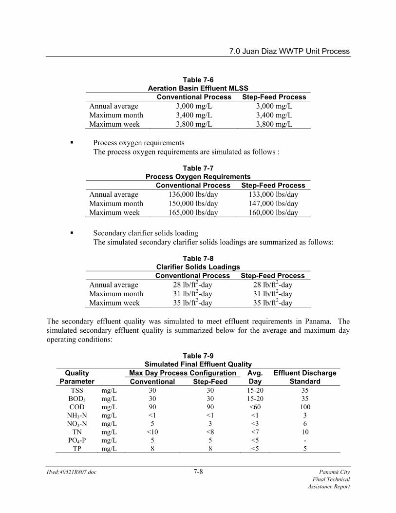
7.0 Juan Diaz WWTP Unit Process Table 7-6
Aeration Basin Effluent MLSS Conventional Process Step-Feed Process
Annual average 3,000 mg/L 3,000 mg/L Maximum month 3,400 mg/L 3,400 mg/L Maximum week 3,800 mg/L 3,800 mg/L
Process oxygen requirements The process oxygen requirements are simulated as follows :
Table 7-7 Process Oxygen Requirements
Conventional Process Step-Feed Process Annual average 136,000 lbs/day 133,000 lbs/day Maximum month 150,000 lbs/day 147,000 lbs/day Maximum week 165,000 lbs/day 160,000 lbs/day
Secondary clarifier solids loading The simulated secondary clarifier solids loadings are summarized as follows:
Table 7-8 Clarifier Solids Loadings
Conventional Process Step-Feed Process Annual average 28 lb/ft2-day 28 lb/ft2-day Maximum month 31 lb/ft2-day 31 lb/ft2-day Maximum week 35 lb/ft2-day 35 lb/ft2-day
The secondary effluent quality was simulated to meet effluent requirements in Panama. The simulated secondary effluent quality is summarized below for the average and maximum day operating conditions:
Table 7-9 Simulated Final Effluent Quality
Max Day Process Configuration Quality Parameter
Conventional Step-Feed
Avg. Day
Effluent Discharge Standard
TSS mg/L 30 30 15-20 35 BOD5 mg/L 30 30 15-20 35 COD mg/L 90 90 <60 100
NH3-N mg/L <1 <1 <1 3 NO3-N mg/L 5 3 <3 6
TN mg/L <10 <8 <7 10 PO4-P mg/L 5 5 <5 -
TP mg/L 8 8 <5 5
Hwd:40521R807.doc 7-8 Panamá City Final Technical Assistance Report
7.0 Juan Diaz WWTP Unit Process
Both the conventional and the step-feed process configurations provide an effluent that can meet the Panamanian effluent standards under average daily loads. However, during the simulated maximum day loading, adequate phosphorus removal may not occur from the biological process alone. Therefore, provisions for alum addition will be made to ensure compliance with effluent phosphorus limits at all times.
The step-feed process offers slightly better effluent quality under maximum day conditions while requiring less aeration basin volume. Process oxygen requirements are slightly less as well. Therefore, the step feed nitrification/denitrification process is the recommended configuration for the activated sludge biological treatment methodology.
7.3.1.3 Aeration System Until the rise in power costs evidenced in the late 1970s, diffuser efficiency could be ignored relative to maintenance free service. Almost universally, simple, coarse bubble devices or surface aerators were used in sewage treatment. As power costs rose, more complex but efficient devices came into use, often with the burden of prohibitively high maintenance costs. Successive designs improved on maintenance until today, when many high efficiency, low maintenance aeration devices are in widespread use. Two systems commonly in use today are the swing type and ceramic dome diffusers.
The two most cost efficient alternatives are: (1) medium bubble expandable tube-type diffusers mounted on swing-out assemblies; and (2) fine bubble ceramic dome type diffusers arranged in a full floor fixed grid pattern.
Although lower in oxygen transfer efficiency, the principal advantage of the swing-type diffuser is the ability to repair units while the process is in operation. The major disadvantages are higher maintenance costs associated with enlargement of holes and tearing of the expandable tube membranes.
The ceramic dome system consists of a fixed grid piping system, with ceramic dome type diffuser units spaced throughout the tank bottom. Although the maintenance frequency is less than that experienced by swing-out type diffusers, the basin must be drained each time the ceramic dome diffusers are to be cleaned. The principal advantages of the ceramic dome system are high oxygen transfer efficiency and the resulting, lower power consumption. For large capacity wastewater treatment plants, the energy cost savings typically associated with fine bubble diffusers far exceeds the additional initial capital cost on a present worth basis.
Therefore, a fine bubble ceramic dome diffused aeration system is recommended. Three 500 HP blowers will be installed (2 + 1 standby) to supply air to the diffuser system of each aeration basin.
7.4 Final Clarification
Hwd:40521R807.doc 7-9 Panamá City Final Technical Assistance Report
Secondary clarifiers provide a quiescent zone to allow settling of suspended materials coming from the aeration basins. Conservative design necessitates that clarifiers be sized for a maximum
7.0 Juan Diaz WWTP Unit Process
Hwd:40521R807.doc 7-10 Panamá City Final Technical Assistance Report
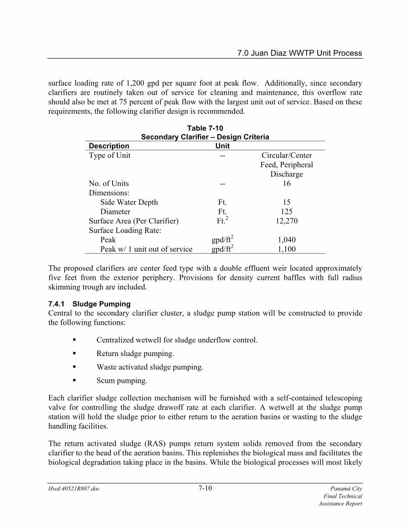
surface loading rate of 1,200 gpd per square foot at peak flow. Additionally, since secondary clarifiers are routinely taken out of service for cleaning and maintenance, this overflow rate should also be met at 75 percent of peak flow with the largest unit out of service. Based on these requirements, the following clarifier design is recommended.
Table 7-10 Secondary Clarifier – Design Criteria
Description Unit Type of Unit -- Circular/Center
Feed, Peripheral Discharge
No. of Units -- 16 Dimensions: Side Water Depth Ft. 15 Diameter Ft. 125 Surface Area (Per Clarifier) Ft.2 12,270 Surface Loading Rate: Peak gpd/ft2 1,040 Peak w/ 1 unit out of service gpd/ft2 1,100
The proposed clarifiers are center feed type with a double effluent weir located approximately five feet from the exterior periphery. Provisions for density current baffles with full radius skimming trough are included.
7.4.1 Sludge Pumping Central to the secondary clarifier cluster, a sludge pump station will be constructed to provide the following functions:
Centralized wetwell for sludge underflow control.
Return sludge pumping.
Waste activated sludge pumping.
Scum pumping.
Each clarifier sludge collection mechanism will be furnished with a self-contained telescoping valve for controlling the sludge drawoff rate at each clarifier. A wetwell at the sludge pump station will hold the sludge prior to either return to the aeration basins or wasting to the sludge handling facilities.
The return activated sludge (RAS) pumps return system solids removed from the secondary clarifier to the head of the aeration basins. This replenishes the biological mass and facilitates the biological degradation taking place in the basins. While the biological processes will most likely

7.0 Juan Diaz WWTP Unit Process
Hwd:40521R807.doc 7-11 Panamá City Final Technical Assistance Report
be operated with a return sludge feed of approximately 50% of the influent flowrate, higher return feeds are often desirable and necessary. Therefore, RAS pump sizing has been performed to accommodate recycle rates up to 100%. A total of four sludge pump stations are proposed. Each would serve four secondary clarifiers. The proposed design criteria for the RAS pumps in each station are presented in Table 7-11.
Table 7-11 RAS Pumping - Design Criteria
Description Unit No of Units -- 4 (3+1) Design Capacity (100% recycle) gpm 17,700 Drive Type -- Variable Frequency
Excess activated sludge is continuously "wasted" from the system to maintain a Mixed Liquor Suspended Solids (MLSS) level in the aeration basins which is consistent with the desired mean cell residence time. The waste activated sludge (WAS) pumps will waste excess sludge to the solids processing facilities. Design criteria for the WAS pumps in each station is presented in Table 7-12.
Table 7-12 WAS Pumping - Design Criteria
Description Unit No of Units -- 2 (1+1) Design Capacity gpm 350 Drive Type -- Variable Frequency
In addition, each clarifier will be furnished with a full radius scum trough. The scum will be collected at the sludge pump station scum wet well. The collected scum will be pumped back to the head end of the plant by one of two (1 + 1 standby) recessed impeller type constant speed pumps at each clarifier scum pit.
7.5 Disinfection Chlorination facilities are required to provide disinfection for the ultimate discharge to Panamá Bay and to support the following process operations:
Influent pre-chlorination (backup odor control, when required).
Return Sludge Chlorination (filamentous bacteria control)
Pretreatment Building Odor Control Facility chlorine solution demand.
Solids Thickening and Dewatering Building Odor Control Facility chlorine solution demand.

7.0 Juan Diaz WWTP Unit Process
Hwd:40521R807.doc 7-12 Panamá City Final Technical Assistance Report
The proposed chlorination facility will include:
Enclosed chlorine building, including an emergency chlorine cylinder scrubber
Chlorine scales.
Eight 8,000 lbs/day evaporators
Panamá regulations require pathogen and virus control for effluent discharge to receiving water bodies. Such requirements are typically referred to as high level disinfection and, as such, must meet the following disinfection criteria:
1 mg/l chlorine residual at 15 minutes detention time at peak flow.
1 mg/l chlorine residual at 30 minutes detention time at average flow.
Given the proximity of the proposed Juan Diaz site to Panamá Bay, the above detention time criteria can be met in the effluent canal prior to discharge. This is a common practice in the United States and throughout the world.
7.6 Effluent Disposal Effluent disposal will be through an effluent discharge canal which will connect to a 108-inch diameter diffuser to Panamá Bay. The diffuser will have a length of approximately 100 meters and will be located below the low tide elevation.
7.7 Material Balance Based on the design wastewater loadings, and the required effluent limits, a material mass balance was determined. A detailed mass balance diagram is shown in Appendix A. Figure 7-2 summarizes the material balance provides approximate quantities and concentrations of pertinent parameters at various locations throughout the treatment plant process. Figure 7-2 also provides a process flow schematic.
7.8 Solids Stabilization and Disposal Solids processing consists of a number of physical, chemical and biological operations which are combined in series and/or in parallel as required to produce the required end product. Unit process operations applicable to solids treatment can be categorized into three major groups:
Thickening
Stabilization
Dewatering
Each of these unit operations contains various processes which achieve a desired result. The determination of the preferred method for sludge processing at the proposed Juan Diaz Wastewater Treatment Plant is dependent on the ultimate disposal method. A detailed

7.0 Juan Diaz WWTP Unit Process
Hwd:40521R807.doc 7-13 Panamá City Final Technical Assistance Report
evaluation of disposal alternatives was performed and is included in a separate report entitled Panamá City Sludge Management Feasibility Study, June 2003 by Hazen and Sawyer.
The Feasibility Study evaluated sludge treatment technologies that would provide, at a minimum, sufficient stabilization to meet Panamá’s Class 1 sludge classification. The study did not evaluate thickening or dewatering options. For comparative purposes, it was assumed that all sludge alternatives would include gravity belt thickeners and centrifuge dewatering to provide a sludge with a minimum of 25% total solids (dry weight).
Screening of numerous technologies led to the creation of three viable sludge management alternatives: (1) Anaerobic Digestion, (2) Lime Stabilization, and (3) Thermal Drying with Anaerobic Digestion. The disposal method for each alternative included on-site monofilling for the first five years and off-site hauling to beneficial use sites for all subsequent years. The costs for each alternative are summarized in Table 7-13.
Table 7-13 Present Worth Summary
Alternative 1
Anaerobic Digestion
Alternative 2
Lime Stabilization
Alternative 3 Thermal Drying
w/Anaerobic Digestion
Construction Cost Process $26,100,000 $3,697,500 $50,141,000 Landfill 7,050,576 9,225,067 3,697,809
O&M Present Worth Process 1,479,337 7,779,97 10,507,784 Landfill 1,955,893 2,856,631 782,989 Sludge Transportation & Disposal 3,537,934 5,420,886 961,395
Total Present Worth $40,123,741 $28,979,979 $66,090,976 Total Annual Worth $4,979,356 $3,596,415 $8,201,890 Annual Worth / Dry Ton $243 $176 $401
Based on these costs, as well as several qualitative criteria, the following sludge management recommendations were made:
1. Base Recommendation: Alternative No. 1: Anaerobic Digestion
2. Alternate Recommendation: Alternate No. 2: Lime Stabilization
The anaerobic digestion alternative is the base recommendation. This process is a proven technology that will meet Panamá’s needs while providing a marketable product for beneficial end use. Also, this alternative has lower risk than lime stabilization. Not only does it have a
7.0 Juan Diaz WWTP Unit Process
Hwd:40521R807.doc 7-14 Panamá City Final Technical Assistance Report
more flexible end product in terms of marketability, but it also has more flexibility in terms of operation. The storage capacity of the digesters provides flexibility in case of process upsets. In the event of process problems, operations staff can stop processing sludge, let it accumulate in the digesters, and work out the process issues. In contrast, lime stabilization is a continuous process and does not provide storage in the event process issues arise.
While lime stabilization does not provide storage, it does have other positive attributes such as simplicity of operation and low capital costs to name a few. Because of lime stabilization’s significantly lower capital costs, it is considered an alternate recommended option should capital costs become a limiting criteria. The Coordinating Unit can review the two recommended options and select the plan that most appropriately meets their needs.
7.8.1 Sludge Thickening Solids are thickened to decrease the capital and operating costs of subsequent processing steps by substantially reducing the volume of the waste sludge to be handled. Waste activated sludge from the liquid treatment process is expected to have a solids concentration of approximately one percent. Thickening to a minimum four percent solids concentration (40,0000 mg/l) results in a volume reduction of approximately ninety percent.
Various methods are available for thickening waste activated sludge (WAS). The three processes most commonly used for municipal WWTPs include:
• Dissolved Air Flotation (DAF) The DAF process concentrates sludge as a result of the attachment of minute bubbles of air to the sludge solids, thereby reducing their specific gravity to less than that of water. The attached particles then float to the surface of the thickener tank and are removed by a skimming mechanism.
• Gravity Belt Thickening With gravity belt thickening, sludge becomes concentrated as its free water drains by gravity through a porous horizontal belt. A gravity belt thickener (GBT) resembles the gravity drainage zone of a typical sludge dewatering belt filter press.
• Centrifugal Thickening The liquid/solid separation during centrifugal thickening (CFT) is analogous to the separation process in a centrifugal sludge dewatering machine except it is performed at lower speeds. Separation results from the centrifugal force driven migration of the sludge solids through the suspending liquid.
The three types of thickening methods have all been used successfully to thicken waste activated sludge. While the capital costs and chemical requirements of all three processes are approximately equivalent, Gravity Belt Thickening has a substantially lower power requirement than the other two processes. The power requirement for Gravity Belt Thickening is less than
7.0 Juan Diaz WWTP Unit Process
Hwd:40521R807.doc 7-15 Panamá City Final Technical Assistance Report
one-half that of Centrifuge Thickening and less than one-fifth that of Dissolved Air Flotation. Therefore, use of Gravity Belt Thickeners is recommended.
7.8.2 Sludge Stabilization Sludge stabilization processes achieve two important results, both of which are critical to the ultimate disposal of the sludge. First, stabilization breaks down unstable, less odorous, putrescible organic matter into more stable organic compounds that are easier to dewater. In addition, stabilization processes achieve high degrees of pathogenic organism destruction, thus reducing the health risks associated with subsequent handling and disposal/use of the product.
The four most common stabilization processes used for municipal WWTPs are evaluated herein and include:
Anaerobic Digestion
Aerobic Digestion
Composting
Lime Stabilization
The key factor in selecting the appropriate sludge stabilization process for a given treatment facility is the method of ultimate solids disposal planned for the facility. The evaluation entitled Panamá City Sludge Management Feasibility Study, June 2003 by Hazen and Sawyer recommended anaerobic digestion for stabilization as the finished product has fewer odor problems upon subsequent rewetting.
The anaerobic digestion process consists of the breakdown of organic matter by anaerobic and facultative microorganisms in the absence of molecular oxygen. Anaerobic digestion is a two phase process. The first phase involves the conversion of complex organic matter to volatile acids by a group of organisms referred to as acid formers. The second step includes the conversion of volatile organic acids to methane gas and carbon dioxide by a group of organisms referred to as gas formers. The primary end products of anaerobic digestion are methane gas, carbon dioxide and stabilized solids. Total solids are reduced by up to thirty-five percent. The remaining solids are well stabilized and have a low putrefaction and odor potential.
The basis of design criteria for anaerobic digestion are:
0.10 lbs VSS/ft3 - day (maximum)
20 day hydraulic detention time
Based on these standards and a volatile solids contents of 80-85% with corresponding minimum volatile solids destruction rate of 40%, the following design criteria result:

7.0 Juan Diaz WWTP Unit Process
Table 7-14 Anaerobic Digestion - Design Criteria
Description Unit No. of Primary Units -- 6 Dimensions Diameter ft 84 Sidewater Depth ft 30 Bottom Slope -- 4:1 Volume (per digester) ft3 185,000 Total Volume ft3 1,110,000 gallons 8,300,000 Hydraulic Detention Time All Tanks days 21 With Tank Out of Service days 18 Solids Loading Rate All Tanks lbs VSS/ft3-day 0.10 W/1 Tank Out of Service lbs VSS/ft3-day 0.12
7.8.3 Sludge Dewatering Dewatering is best described as the process of removing water from biosolids. Dewatering can either precede or follow the stabilization process depending on the selected treatment scheme. The choice of a dewatering process, as has been discussed earlier, is dependent on the means of ultimate disposal. The most common methods of sludge dewatering at municipal WWTPs are:
Centrifuges
Belt Presses
Even with the addition of polymer, belt presses typically achieve a sludge cake with a solids content of 16-18% (dry weight). Centrifuges routinely achieve 25-27% solids. Because the Panamá regulations require a minimum solids concentration of 25% (dry weight) for landfilled sludge, belt presses were not considered for the Juan Diaz WWTP.
Centrifugation involves centrifugal force that is applied to a liquid sludge stream, which accelerates the separation of the liquid and solid fractions. The use of centrifuges for dewatering sludge is performed at higher speeds resulting in high power demand. The process involves both clarification and compaction. The critical design parameter for centrifugal dewatering is typically the hydraulic loading rate.
Hwd:40521R807.doc 7-16 Panamá City Final Technical Assistance Report
7.0 Juan Diaz WWTP Unit Process
Hwd:40521R807.doc 7-17 Panamá City Final Technical Assistance Report
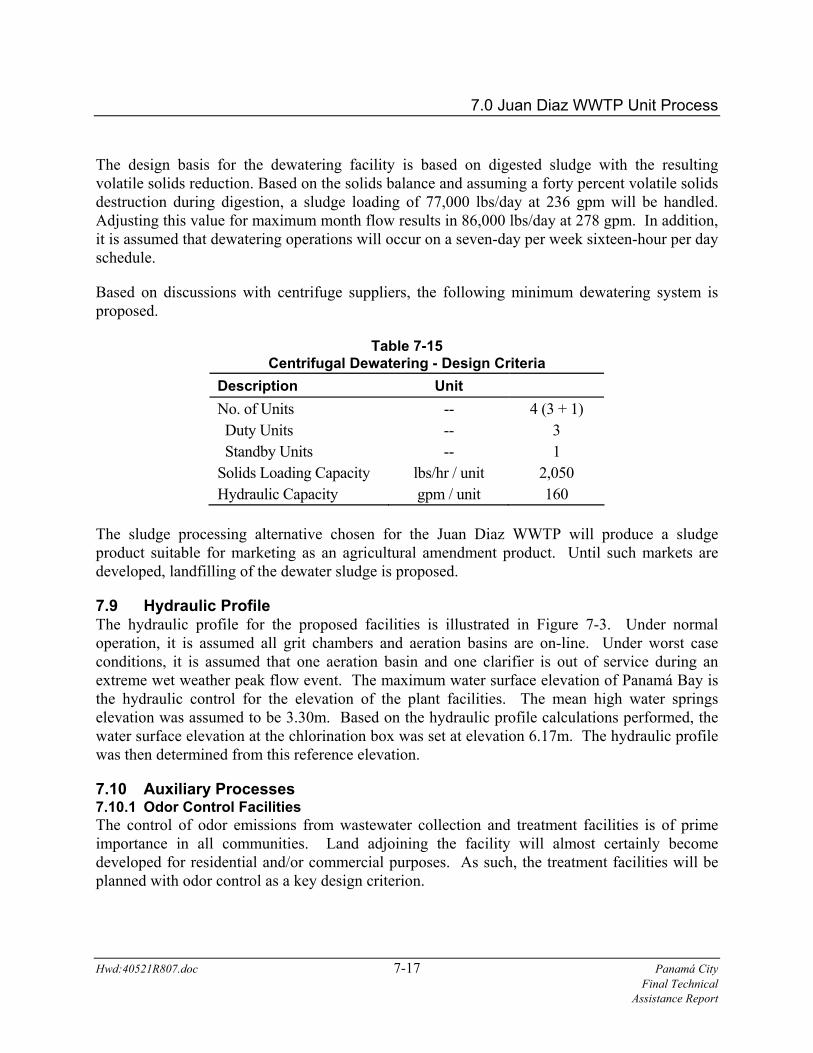
The design basis for the dewatering facility is based on digested sludge with the resulting volatile solids reduction. Based on the solids balance and assuming a forty percent volatile solids destruction during digestion, a sludge loading of 77,000 lbs/day at 236 gpm will be handled. Adjusting this value for maximum month flow results in 86,000 lbs/day at 278 gpm. In addition, it is assumed that dewatering operations will occur on a seven-day per week sixteen-hour per day schedule.
Based on discussions with centrifuge suppliers, the following minimum dewatering system is proposed.
Table 7-15 Centrifugal Dewatering - Design Criteria
Description Unit No. of Units -- 4 (3 + 1) Duty Units Standby Units
-- --
3 1
Solids Loading Capacity Hydraulic Capacity
lbs/hr / unit gpm / unit
2,050 160
The sludge processing alternative chosen for the Juan Diaz WWTP will produce a sludge product suitable for marketing as an agricultural amendment product. Until such markets are developed, landfilling of the dewater sludge is proposed.
7.9 Hydraulic Profile The hydraulic profile for the proposed facilities is illustrated in Figure 7-3. Under normal operation, it is assumed all grit chambers and aeration basins are on-line. Under worst case conditions, it is assumed that one aeration basin and one clarifier is out of service during an extreme wet weather peak flow event. The maximum water surface elevation of Panamá Bay is the hydraulic control for the elevation of the plant facilities. The mean high water springs elevation was assumed to be 3.30m. Based on the hydraulic profile calculations performed, the water surface elevation at the chlorination box was set at elevation 6.17m. The hydraulic profile was then determined from this reference elevation.
7.10 Auxiliary Processes 7.10.1 Odor Control Facilities The control of odor emissions from wastewater collection and treatment facilities is of prime importance in all communities. Land adjoining the facility will almost certainly become developed for residential and/or commercial purposes. As such, the treatment facilities will be planned with odor control as a key design criterion.

7.0 Juan Diaz WWTP Unit Process
Hwd:40521R807.doc 7-18 Panamá City Final Technical Assistance Report
Organic vapors are generated by the anaerobic decomposition of compounds containing nitrogen and sulfur (or by the introduction of waste chemicals in the wastewater). Mercaptans, skatoles and indoles are examples of malodorous nitrogen and sulfur bearing compounds. Organic acids, aldehydes, esters and ketones can also cause offensive odors. Hydrogen sulfide is the most commonly known odorous gas associated with domestic wastewater collection and treatment facilities. For the purposes of this report, the term hydrogen sulfide is generally assumed to include those concentrations of organic vapors typically found in domestic wastewater.
The concentration of total sulfide in raw wastewater reaching a treatment plant depends upon temperature, pH, travel time and velocity, biological activity, upstream control programs and other factors. Based upon experience in tropical climates, the estimated total sulfide content in raw wastewater is listed in Table 7-16.
Table 7-16 Projected Sulfide Levels in Raw Wastewater Total Sulfides
(mg/l) Average Level 20 Normal Range 10-30 Peak 50
The anticipated average hydrogen sulfide levels in air range between 10 to 30 ppm, with occasional peak levels of up to 50 ppm Air stream odor control facilities for the Juan Diaz WWTP will be based upon average H2S levels of 20 ppm and peak levels of 50 ppm.
There are three general approaches towards the development of an odor control program. These are:
Elimination of the odor source.
Elimination of the odor perception.
Treatment of the source.
Source elimination is usually not a realistic alternative with the exception of good housekeeping, proper facilities design and operation, and control of discharges.
Elimination of the odor perception refers to the dilution of odors with fresh air or masking. Masking is the process of superimposing a pleasant odor over an obnoxious odor. The efficacy of masking is often uncertain and the process tends to be high in chemical cost. Furthermore, the public often objects to the pleasant odor with the same vehemence as their objection to the unpleasant odor.

7.0 Juan Diaz WWTP Unit Process
Hwd:40521R807.doc 7-19 Panamá City Final Technical Assistance Report
Treatment of the source is the recommended approach for odor control at wastewater treatment plants.
7.10.1.1 Odor Sources The major odor producing operations at the proposed treatment plant are anticipated to be:
Pretreatment Building; including screens, grit chambers, degritting, etc.
Solids Thickening and Dewatering Building.
These structures will be designed to be completely enclosed. Ductwork will be provided to odor control systems. Upon installation of the system, air will be continually drawn into structures to maintain a slight negative pressure and ensure against the escape of odorous gases.
7.10.1.2 Odor Treatment Two stage packed tower odor control systems are proposed for installation to treat all air within odorous process areas prior to exhaust into the outside air. Additionally, sanitary and scum pumping stations will be ventilated through self-contained activated carbon absorption units.
In the first stage of the scrubber system, caustic solution will be used as the scrubbing liquid. This stage will achieve hydrogen sulfide (H2S) removal. The second stage will employ sodium hypochlorite to remove sulfur and other odorous compounds not readily absorbed in the first stage.
The self-supporting and free-standing scrubbers will be manufactured of corrosion-resistant fiberglass reinforced plastic. Scrubber vessel internal features include built-in scrubbing solution holding tank, plastic media, PVC scrubbing solution spray header, mist eliminator. The scrubber vessels will also be provided with man ways for access to the scrubber internals, nozzles for chemical addition, scrubbant recirculation, makeup water and drains. Recycle pumps, chemical feed systems ductwork and air handling equipment and appurtenances will be suitably corrosion-resistant for the service intended.
Air will enter the first stage scrubber below the packed bed and pass upward through the bed and out the top of the tower. The air will then pass through the second stage scrubber in a similar manner. Scrubbing solution will enter the towers through spray headers above the packed bed and pass downward through the beds removing the odors from the upward moving air.
The scrubbing solution from each scrubber is collected in the lower section of the tower with sufficient detention time to complete the H2S oxidation reaction. Chemical recycle pumps recirculate the solution back to the top of the towers for reuse of unreacted chemical. Make-up chemicals and make-up water will be added to the scrubbers to maintain the scrubber solution strength at necessary levels.
In order to prevent the build-up of objectionable materials in the systems, a small quantity of solution will be removed from the system on a continuous basis. This flow is referred to as a

7.0 Juan Diaz WWTP Unit Process
Hwd:40521R807.doc 7-20 Panamá City Final Technical Assistance Report
"blowdown". Automatic level controls will be provided for make-up water. The chemical feed rates to the scrubber systems will be automatically regulated by controllers to respond to changes in odor concentrations in the building air and exhaust will be continuously monitored. Hydrogen sulfide levels confirm the performance of the system and to monitor hydrogen sulfide levels in the work areas. and odor concentrations
Chlorinated water will be piped from the chlorination facilities.
7.10.1.3 Ventilation Systems The pretreatment building and the solids thickening and dewatering building will be completely enclosed and furnished with ventilation ducts to provide a means for collecting air that will transport the odorous gasses to the odor control systems.
Typically, ventilation systems in working areas will be designed to provide twelve air changes per hour. In normally non-working areas such as in the pretreatment screen channels and the grit chambers, ventilation systems will provide six air changes per hour. Provisions will be made so that the air inlet capacity to the building is equal to the capacity of the odor control system. Adjustable wall louvers and supply fans will be utilized to achieve this balance.
Exhaust duct air intakes will be located over point odor sources such as screens, discharge chutes, thickening and dewatering equipment, hoppers and solids handling containers. Odorous air will be collected and treated by the scrubber system.
Instrumentation, electrical and control rooms will be isolated from process areas. These rooms will be provided with separate air conditioning and ventilation systems to isolate personnel and protect electrical equipment.
7.10.1.4 Housekeeping While most of the attention to odor control at a treatment plant is based upon normal operation, it is important to recognize that some infrequent operations can produce substantial odors and must be controlled. Plant startup can produce odor problems prior to establishing a stable process operation. Periodic emptying of various plant structures for routine maintenance can also pose special odor problems that must be controlled.
In every wastewater plant there are occasional odor sources resulting from poor housekeeping, failure of equipment, plus incidental items such as leaving doors, windows and hatches opened on structures when they should be closed.
Plant personnel must be conscious of potential odor sources at all times and be aware of what can be done to eliminate them before problems arise.
7.0 Juan Diaz WWTP Unit Process
Hwd:40521R807.doc 7-21 Panamá City Final Technical Assistance Report
7.10.2 Control and Information Systems Computerized monitoring and control systems are recognized as a reliable low cost approach for the numerous control and information gathering tasks necessary in wastewater collection, treatment and disposal facilities. The major advantage of digital control systems over hardwired control systems (composed of free standing panels and electronic equipment) is the ability to monitor numerous process elements at a reasonable cost while providing a system which can be tailored to meet specific user needs. In turn, this can facilitate improved operational reliability at all functional levels (i.e., process, plant operations, maintenance management and administration). Additional advantages include:
In-plant wire runs can be substantially reduced by eliminating most or all long distance runs between final monitoring and control elements and centralized analog display/control panels.
Digital recording eliminates the need for panel mounted electromechanical recording devices (circular charts, strip charts, etc.) and related operator attendance to maintain units in working order.
Digital monitoring relieves plant operating staff from routine data reporting duties and provides additional opportunity to observe process operations and take corrective action in a timely manner.
The operator's console not only permits the operator to rapidly access and display desired information in pictorial, graphical or alphanumeric format, but also to quickly respond to and correct abnormal process operating conditions. Guidelines for corrective and restorative procedures can also be displayed either automatically, or upon operator request.
The use of historical data gathered by the system permits past operating experiences to be "remembered". Such an arrangement makes the control system less vulnerable to sensor failures because missing information can be based on related operating data. For example, if the main influent meter became disabled, a relationship between influent pump speed and historical influent flow rates could be quickly developed and implemented to approximate and replace the missing process variable (influent flow). Control can quickly resume.
Maintenance planning, cost control and agency reporting functions can be easily performed at plant management and public works management levels. This frees plant operating personnel from routine clerical functions and contributes to increased personnel productivity.
In the past, large expensive mimic panels with an array of fixed graphics, indicator lights, switches, etc., were employed in control rooms for this purpose. In addition to their high cost

7.0 Juan Diaz WWTP Unit Process
Hwd:40521R807.doc 7-22 Panamá City Final Technical Assistance Report
and large space requirements, panel maintenance, as well as modifications to reflect process changes were difficult and expensive to implement.
Due to their lack of flexibility, systems of more recent vintage employed a combination of minicomputer systems and colorgraphic CRT terminals in one or more consoles to provide a flexible operator interface that was significantly less expensive, monitored and reported alarm events, maintained long term operating histories as well as provided a convenient means for the operator to effectively determine overall plant status and process performance. Early systems were centralized with all wiring to a single location. More recent systems take advantage of networking and distributed computing to reduce long wire runs and provide computer resources or local monitoring and control.
Numerous minicomputer based systems have been installed and are currently operating successfully in the water and wastewater utilities system environment, the most successful being of the distributed type. Although minicomputer based systems have historically offered much greater flexibility than free standing mimic panels, hardware and software elements are usually vendor specific and require commitment to a single source for long term support.
During the past five to seven years, significant advances have occurred in the development of personal computer system hardware and software capabilities. Increase capabilities and ease of use, together with competitive pricing has led to their proliferation in the business and home environment as well as in the process control industry. The result of the PC based systems introduction to the process control industry is the emergence of "industry standard" equipment and software that can be easily maintained and tailored to meet the specific needs of the user without the dependence upon a single vendor for long term support.
Modern control system designs generally utilize a distributed control concept in which ruggedized microprocessor based controllers (commonly referred to as programmable logic controllers or PLCs) are installed within the equipment panels or local control panels at key plant locations to monitor and control local equipment and processes. Where information needs to be exchanged between units, a fiber optic data highway or local area network (LAN) is employed. PLC systems have become standard throughout the manufacturing and electrical industries over the past 15-20 years with units available from several major suppliers, including:
Square D Allen Bradley General Electric Siemens
Due to their modular design, sizes, capabilities, and cost will vary to meet the specific needs of the application. To assist the operator in local monitoring and/or control, area control panels may include manual selector switches (hand/off/automatic), status indication lights (run, fail) and local display of key process variables (levels, flows, etc). The current industry trend is the
7.0 Juan Diaz WWTP Unit Process
Hwd:40521R807.doc 7-23 Panamá City Final Technical Assistance Report
implementation of manufacturer standard programmable logic controllers for localized process monitoring and control together with a fiber optic data highway network and personal computer based operator work stations for process coordination, status monitoring and operator intervention.
To summarize, distributed control systems, based upon industry standard programmable logic controllers (PLCs) and personal computer based operator work stations are well recognized for inherent advantages in terms of reliability, cost of hardware, flexibility, ease of expansion, open architecture and improved tolerance to operating environments.
7.10.2.1 Information Needs The principal advantage of computerized monitoring and control systems is the ability to quickly and efficiently collect information for process control, as well as long term facilities management and administrative functions. Real-time data (flow changes, level changes, equipment status, alarms, etc), is generally presented in graphical form to enable the operator to quickly respond to process changes and events. Historical data is usually maintained in an internal database to support certain real-time system functions (trending, status displays, operator control, etc), as well as in commercial formats such as D-Base and Microsoft Excel for data reporting and analysis. This format also provides a common interface to other commercially available software. Generally, real-time data is of most importance to plant operations staff to support day-to-day process management. Historical data is of greater importance to plant management and utilities administration staff.
The planned Juan Diaz WWTP consists of several principal operational and administrative areas. The physical and functional distribution of control and information system elements will be designed to parallel the distribution of the monitored and/or controlled equipment. In addition, the system design will parallel the needs of the operational and administrative staff. For example, staff assigned to the solids processing facilities need to be intimately aware of the status of the solids thickening, digestion and dewatering systems; the status of the influent screens may be of far less importance. In comparison, the long term growth trends of wastewater flows is critical to treatment plant staff located in the administration building to properly plan infrastructure improvements to meet these demands, but unnecessary for day-to-day plant operations.
7.10.2.2 Recommended System Based upon process monitoring, control and information management needs and modern open architecture distributed process control system concepts, a PLC based monitoring and control system with an interconnecting fiber optic data highway and personal computer based operation work stations is recommended. Principal elements are described below.
Local Process Area Control Panels Local control panels for key process areas and equipment such as influent pretreatment, engine-generators sets, return sludge pumping, solids thickening and dewatering etc., will be provided for:
7.0 Juan Diaz WWTP Unit Process
Local process indication.
Status indication and manual control of process equipment.
Local fault indication.
Common interface between process equipment, instrumentation and the plant control system.
The monitoring and control devices may range from simple hand/off/auto (HOA) selector switches to more extensive, free-standing panels for complex rotating equipment. Where appropriate, panels will include analog and status indicators, backup analog type control of key process, alarm annunciator systems, and manual control facilities. The degree of local instrumentation provided will vary between the process areas.
Information which would be retransmitted from a local control panel to the PLC for control and then to the operator work stations for over the data highway, will be limited to the data that is necessary to permit proper operation at the higher levels. For example, it is unnecessary to re-transmit the status of all belt tracking and drive signals associated with a belt thickener to the PLC, but it may be appropriate to indicate on the local panel for reference by the mechanic, should a shutdown occur.
Similarly, all alarms may not need to be re-transmitted to the PLC but could be grouped into general classifications such as pump fault (non-critical), pump fault (critical), engine fault, etc. In summary, the control and monitoring panels associated with packaged equipment systems and/or local process areas can serve as data concentrators or backup control panels (as necessary) and relieve the PLC from accumulating unnecessary data.
Programmable Logic Controllers (PLCs) Functionally, a PLC consists of a power supply, memory section, and modular input/output circuit boards. One can accommodate several pieces of equipment. Circuit board fault detection is provided by Light Emitting Diode (LED) indicators on the front of each module. Should a module fail, the unit can be quickly removed and replaced.
Relay-type logic is loaded into a PLC via a portable programming device. The programming device issued to develop the control relay ladder logic diagram consists of schematic representations of relay contacts, coils, timers, etc. The completed control schematic can be stored and reused for similar equipment items or for fast reprogramming should PLC circuit board repair/replacement be necessary. Alternatively, the relay logic can be developed on the operator work stations and "downloaded" to the PLC via the data highway. The principal advantage offered by the PLC is the reduction of in-plant electromechanical devices (and associated shortcomings) and their replacement with solid state circuitry.
Hwd:40521R807.doc 7-24 Panamá City Final Technical Assistance Report

7.0 Juan Diaz WWTP Unit Process
Hwd:40521R807.doc 7-25 Panamá City Final Technical Assistance Report
PLCs will be provided in major process areas for process monitoring and control. In the event of power failure, an uninterruptible power supply (UPS) will be furnished with each unit to provide a minimum of thirty minutes of standby power until normal power is restored.
Digital Data Highway The digital data highway connects the PLCs with the Local Area Work Stations, as well as the Plant Control Center (PCC). The data highway will consist of a redundant pair of fiber optic cables. Fiber optic cabling is recommended to avoid spikes and surges normally encountered in areas of high lightning potential.
The digital data highway system achieves a greater degree of system availability than a centralized system because of a highway-connected device has the capability of directly communicating with any other high-way connected device. Hence, even if the entire Plant Control Center system should fail, the distributed network of PLCs will continue to operate the plant.
Plant Control Center/Local Area Work Stations The Plant Control Center will be designed to facilitate two operator work stations as part of a centralized operating center located in the new Operations Building as well as two additional work stations located in the Pretreatment Building and Solids Processing Building respectively. Major features of the PCC will include:
Supervision and coordination of subordinate distributed PLCs.
Access and display of system information items in schematic, graphic and alphanumeric format.
Display of potential corrective and restorative procedures for operator guidance.
Alarm annunciation, classified as follows:
- Critical: Human safety is threatened and immediate attention is required.
- Important: Physical plant is threatened and immediate attention is required.
- Auxiliary: Process requires attention.
Alphanumeric keyboards with password security to permit the generation and modification of displays, report formats, etc.
Control mode selection, as well as setpoint and alarm point adjustments utilizing "fill-in-the-blanks" techniques.
Alarm logging and the generation of shift and daily operating reports employing standard software such as Microsoft Excel.

7.0 Juan Diaz WWTP Unit Process
Hwd:40521R807.doc 7-26 Panamá City Final Technical Assistance Report
In addition to the operator work stations , the plant control center includes:
A file server for historical record keeping purposes.
Two printers, one for alarms and one for reports.
A voice annunciator system for alarm status annunciation. As a part of the process control system, the voice annunciator will alert plant operations staff to new conditions and/or priority alarms by way of synthesized voice from the plant control center. Low power two-way radios are proposed for transmission of voice alarm messages. The two way radios will also double to provide normal two way communication between staff. The radio based on site voice pager system will provide continuous communication capability between plant personnel and the control center.
Network communications will be maintained by a fiber optic system. This approach results in a system of highest reliability, low noise/interference and resistance to electromagnetic interference (lightning).
Uninterruptible power systems (UPS) will be provided in each panel and in the plant control center to provide a protected supply and continuously provide power to all components of the Distributed Control System.
Two local area work stations shall be provided for localized process monitoring at the following locations:
Pretreatment Building:
Screens Grit Removal Aeration Basins Clarifiers RAS Pumps WAS Pumps Odor Control Facility - Pretreatment
Solids Processing Building:
Sludge Thickening Sludge Stabilization Sludge Dewatering Odor Control Facility - Sludge Treatment Electrical Generation Facility

7.0 Juan Diaz WWTP Unit Process
Hwd:40521R807.doc 7-27 Panamá City Final Technical Assistance Report
Each work station shall be PC based. This approach not only ensures operator familiarity with commonly available and repairable equipment, but also supports the wealth of software available to meet specific user needs both current and future.
System Software During the past two or three years, significant advances in PC and minicomputer system networking has led the industry to clearly focus upon interoperability issues. The principal leader in the personal computer field is Microsoft with their Windows series of operating systems which supports a user friendly graphical user interface (GUI) operating environment and complete interoperability of graphics, data and related information between a wide variety of Window based application programs.
The growth of network based personal computer information system solutions coupled with technological advances leading to increased performance at lower cost has resulted in the establishment of the Microsoft Windows based system as the de facto personal computer software standard.
The Microsoft Windows operating environment and related personal computer software products are recommended as a standard to ensure that a base level of core software interoperability is maintained. A number of personal computer based monitoring and control system software suppliers currently offer Windows based packages. Several are adaptations of prior packages with varying levels of technical advances while others, such as the Intellution DMACS Windows based monitoring and control software system was developed from the "ground up" to support full Windows functionality as well as a network based distributed computing environment. Microsoft Excel, which is an industry standard spreadsheet software system is recommended to the employed for report preparation and related analytical functions.
Utilities Support Two additional personal computer based systems are proposed to support facilities maintenance and laboratory management functions. As described for the operator work stations, the personal computers will be based upon the Microsoft Windows operating system for ease of data integration. In addition, each area will be provided with a printer for local hardcopy output.
7.10.3 Standby Power The Juan Diaz WWTP will be capable of processing 102 MGD on an annual average daily basis. The electrical design reflects this concept. An estimate of the equipment needed as well as their required loads is presented in Table 7-17. Standby power is sized for the operating units only and therefore does not include standby units.

7.0 Juan Diaz WWTP Unit Process
Table 7-17 Electrical Loads
Equipment Type Connected
Horsepower Pretreatment Mechanical Screens 18 Screenings Presses 9 Grit Chambers Grit Drive 8 Grit Cyclone / Dewatering Screw 1 Grit Pump 60 Preliminary Treatment Odor Control System Scrubber Fan 25 Recirculation Pumps 20 Chemical Feed Pumps 2 Base Loads 35 Aeration Basins Anoxic Recycle Pumps 80 Nitrified Recycle Pumps 200 Aeration Influent Distribution Channel Mixers 6 RAS Distribution Channel Mixers 6 Process Air Blowers 6000 Trolley/Hoist (Blower Building) 5.5 Base Loads 35 Secondary Clarifiers and Sludge Pump Station Clarifier Drive Units 24 RAS Pumps 900 WAS Pumps 120 Trolley/Hoist (Sludge Pump Station) 5.5 Base Loads (Sludge PS & Clarifier) 35
Hwd:40521R807.doc 7-28 Panamá City Final Technical Assistance Report

7.0 Juan Diaz WWTP Unit Process
Table 7-17 (continued) Electrical Loads
Equipment Type Connected
Horsepower Anaerobic Digestion Digesters Recirculation Pumps 180 Mixers 360 Heat Exchanger Water Pumps 6 Sludge Grinder (No. 1) 18 Sludge Grinder (No. 2) 3 Hot Water Pumps 30 Transfer Pumps 180 Base Load 35 Solids Processing Building Gravity Belt Thickeners Drives 12 Polymer Pump/Mixer 4 Washwater Booster Pump 30 Thickened Sludge Pumps 40 High Solids Centrifuges 1300 Polymer Pump/Mixer 4 Centrate pump 40 Solids Processing Scrubber Fan 125 Tower No. 1 Recirculation Pumps 80 Chemical Feed Pumps 2 Belt Conveyors 30 Trolley/Hoist (Upper Level) 20 Standby Polymer Pump/Mixer (Centrifuges) 1 Standby Polymer Pump/Mixer (Belt Thickeners) 1 Bulk Polymer Transfer Pumps 30 Trolley/Hoist (Lower Level) 5.5 Base Load 35
Hwd:40521R807.doc 7-29 Panamá City Final Technical Assistance Report

7.0 Juan Diaz WWTP Unit Process
Table 7-17 (continued) Electrical Loads
Equipment Type Connected
Horsepower Chlorination Building Hypochlorite Pump No.1 (Pretreatment Odor Control) 1 Hypochlorite Pump No.2 (Solids Process Odor Control) 1 Hypochlorite Pump No.3 (RAS PS #1 Chlorination) 1 Hypochlorite Pump No.4 (RAS PS #2 Chlorination) 1 Hypochlorite Pump No.5 (RAS PS #3 Chlorination) 1 Hypochlorite Pump No.6 (RAS PS #4 Chlorination) 1 Hypochlorite Pump No.7 (Effluent Chlorination) 5 Hypochlorite Pump No.8 (Effluent Chlorination) 5 Base Load 35 Miscellaneous Facilities Administration Building 283 Maintenance Building 71 Miscellaneous Pumps & Equipment 500 Landfill Pump Station 100 Plant Site Pump Station Pump No.1 160 Wastewater Samplers Pretreatment Building (Plant Influent) 0.25 Effluent Pipeline (Outfall) 0.25 Plant Site Pump Station (Recycle Flows) 0.25 Cranes Bridge Crane (Administration Building) 5.5 Trolley Hoist (Maintenance Building) 5.5 Trolley Hoist (Chlorination Building) 5.5 Gasoline Fuel Pump 0.3 Diesel Fuel Pump 0.3
Horsepower Totals 11,348 Operating Horsepower (assumed @ 75% of installed) 8,511 kW Totals 6,349 kVA Totals (80% Power Factor, 90% Efficiency) 8,818
Hwd:40521R807.doc 7-30 Panamá City Final Technical Assistance Report
7.0 Juan Diaz WWTP Unit Process
Hwd:40521R807.doc 7-31 Panamá City Final Technical Assistance Report
7.11 Proposed Treatment Plant Layout Based on the size and quantity of the unit processes discussed herein, a general layout of the proposed Juan Diaz Wastewater Treatment Plant is depicted in Figure 7-4. The treatment plant occupied approximately 36 HA. This site allows for a future expansion to 150 mgd. Preliminary drawings of individual major treatment plant facilities are included in the appendix.